THREE-DIMENSIONAL NUMERICAL … OnLine-First...1 THREE-DIMENSIONAL NUMERICAL INVESTIGATION OF...
14
1 THREE-DIMENSIONAL NUMERICAL INVESTIGATION OF TURBULENT FLOW AND HEAT TRANSFER INSIDE A HORIZONTAL SEMI-CIRCULAR CROSS-SECTIONED DUCT by Kamil ARSLAN Technical and Business College, Çankırı Karatekin University, 18100, Ballıca, Çankırı, Turkey In this study, steady-state turbulent forced flow and heat transfer in a horizontal smooth semi-circular cross-sectioned duct was numerically investigated. The study was carried out in the turbulent flow condition where Reynolds numbers range from 1×10 4 to 5.5×10 4 . Flow is hydrodynamically and thermally developing (simultaneously developing flow) under uniform surface heat flux with uniform peripheral wall heat flux (H2) boundary condition on the duct’s wall. A commercial CFD program, Ansys Fluent 12.1, with different turbulent models was used to carry out the numerical study. Different suitable turbulence models for fully turbulent flow (k-ɛ Standard, k-ɛ Realizable, k-ɛ RNG, k-ω Standard and k-ω SST) were used in this study. The results have shown that as the Reynolds number increases Nusselt number increases but Darcy friction factor decreases. Based on the present numerical solutions, new engineering correlations were presented for the average Nusselt number and average Darcy friction factor. The numerical results for different turbulence models were compared with each other and similar experimental investigations carried out in the literature. It is obtained that, k-ɛ Standard, k-ɛ Realizable and k-ɛ RNG turbulence models are the most suitable turbulence models for this investigation. Isovel contours of velocity magnitude and temperature distribution for different Reynolds numbers, turbulence models and axial stations in the duct were presented graphically. Also, local heat transfer coefficient and local Darcy friction factor as function of dimensionless position along the duct were obtained in this investigation. Key words: simultaneously developing flow, forced convection, semi- circular cross-sectioned duct, friction factor, heat transfer coefficient, turbulent flow, Ansys Fluent 1. Introduction Predicting the pressure drop and forced convective heat transfer under developing flow conditions is quite important in many applications. Turbulent flow and heat transfer in semi-circular channels have received considerable attention due to their practical importance. Especially, turbulent forced convection inside ducts is of interest in the design of solar energy systems, cooling of electronic devices, compact heat exchangers, and cooling cores of nuclear reactors. Full understanding of the prevailing velocity and temperature fields, as well as the pressure drop and heat transfer characteristics, is necessary for the proper design of such systems. Compared to circular cross- sectioned ducts, heat transfer and fluid flow in semi-circular cross-sectioned ducts are complicated [1- 5]. Several studies of flow in straight semi-circular cross-sectioned ducts have been presented in the past. An excellent comprehensive review of forced convection flow in circular and various non- circular duct cross-sections were presented by Shah and London [1], Kakaç et al. [2], and Kakaç and Liu [3]. The flow and heat transfer in semi-circular cross-sectioned duct was investigated firstly by Eckert et al. [4]. Berbish et al. [5] carried out an experimental study for turbulent forced convection heat transfer and pressure drop characteristics of air flow inside a horizontal semi-circular cross-
Transcript of THREE-DIMENSIONAL NUMERICAL … OnLine-First...1 THREE-DIMENSIONAL NUMERICAL INVESTIGATION OF...

1
THREE-DIMENSIONAL NUMERICAL INVESTIGATION OF TURBULENT FLOW AND HEAT TRANSFER INSIDE A HORIZONTAL SEMI-CIRCULAR CROSS-SECTIONED
DUCT
by
Kamil ARSLAN
Technical and Business College, Çankırı Karatekin University, 18100, Ballıca, Çankırı, Turkey
In this study, steady-state turbulent forced flow and heat transfer in a horizontal smooth semi-circular cross-sectioned duct was numerically investigated. The study was carried out in the turbulent flow condition where Reynolds numbers range from 1×10⁴ to 5.5×10⁴. Flow is hydrodynamically and thermally developing (simultaneously developing flow) under uniform surface heat flux with uniform peripheral wall heat flux (H2) boundary condition on the duct’s wall. A commercial CFD program, Ansys Fluent 12.1, with different turbulent models was used to carry out the numerical study. Different suitable turbulence models for fully turbulent flow (k-ɛ Standard, k-ɛ Realizable, k-ɛ RNG, k-ω Standard and k-ω SST) were used in this study. The results have shown that as the Reynolds number increases Nusselt number increases but Darcy friction factor decreases. Based on the present numerical solutions, new engineering correlations were presented for the average Nusselt number and average Darcy friction factor. The numerical results for different turbulence models were compared with each other and similar experimental investigations carried out in the literature. It is obtained that, k-ɛ Standard, k-ɛ Realizable and k-ɛ RNG turbulence models are the most suitable turbulence models for this investigation. Isovel contours of velocity magnitude and temperature distribution for different Reynolds numbers, turbulence models and axial stations in the duct were presented graphically. Also, local heat transfer coefficient and local Darcy friction factor as function of dimensionless position along the duct were obtained in this investigation.
Key words: simultaneously developing flow, forced convection, semi-circular cross-sectioned duct, friction factor, heat transfer coefficient, turbulent flow, Ansys Fluent
1. Introduction
Predicting the pressure drop and forced convective heat transfer under developing flow conditions
is quite important in many applications. Turbulent flow and heat transfer in semi-circular channels have received considerable attention due to their practical importance. Especially, turbulent forced convection inside ducts is of interest in the design of solar energy systems, cooling of electronic devices, compact heat exchangers, and cooling cores of nuclear reactors. Full understanding of the prevailing velocity and temperature fields, as well as the pressure drop and heat transfer characteristics, is necessary for the proper design of such systems. Compared to circular cross-sectioned ducts, heat transfer and fluid flow in semi-circular cross-sectioned ducts are complicated [1-5].
Several studies of flow in straight semi-circular cross-sectioned ducts have been presented in the past. An excellent comprehensive review of forced convection flow in circular and various non-circular duct cross-sections were presented by Shah and London [1], Kakaç et al. [2], and Kakaç and Liu [3]. The flow and heat transfer in semi-circular cross-sectioned duct was investigated firstly by Eckert et al. [4]. Berbish et al. [5] carried out an experimental study for turbulent forced convection heat transfer and pressure drop characteristics of air flow inside a horizontal semi-circular cross-

2
sectioned duct. The variations of surface and mean temperatures, local heat transfer coefficient, local Nusselt number, and local friction factor with the axial dimensionless distance along the duct were presented in this study. Empirical correlations for the average Nusselt number and average Darcy friction factor as a function of the Reynolds number were obtained. Hong and Bergles [6] studied the thermally developing flow in the entrance region of semi-circular cross-sectioned ducts. Uniform heat flux boundary condition was used in the study. Manglik and Bergles [7] analyzed numerically constant property, laminar flow heat transfer in a semi-circular tube with uniform wall temperature. Zhang and Ebadian [8,9] analyzed numerically the steady laminar forced convection and radiation heat transfer for the flow in the entrance region of an internally finned semi-circular cross-sectioned duct. Uniform temperature boundary condition was imposed on the duct’s wall. The hydrodynamically fully developed flow and developing temperature were solved in this study. The developing temperature field in the semi-circular duct with longitudinal fins was obtained analytically/numerically by solving the energy equation employing the method of line (MOL). Yang and Ebadian [10] numerically analyzed the interaction of radiation and forced convection heat transfer in simultaneously developing laminar flow through semi-circular and right triangular ducts having isothermal non-black wall. The numerical results showed that the thermal radiation changes and enhances the characteristics of the convective heat transfer. Etemad [11] and Etemad et al. [12] carried out experimental and numerical studies on the simultaneously developing forced flow and heat transfer to Newtonian and non-Newtonian fluids flowing in semi-circular cross-sectioned ducts. Dong and Ebadian [13] numerically analyzed fully developed natural and forced laminar flow and heat transfer in a vertical semi-circular duct with radial, internal longitudinal fins. It was obtained that both the friction factor and the Nusselt number in the finned tube increase with increasing the Rayleigh number. By comparing the results of finless ducts with those of finned ducts, it was concluded that heat transfer in the semi-circular duct was enhanced by using radial internal fins. Busedra and Soliman [14,15] numerically analyzed laminar mixed convection in the fully developed region of an inclined semi-circular cross-sectioned duct. It was obtained that increasing the Grashof number increases the Nusselt number. Hakan and Oztop [16] conducted an anaytical study of entropy generation in laminar flow through semi-circular cross-sectioned ducts having constant wall heat flux boundary conditions. It was obtained that entropy generation in the semi-circular cross-sectioned ducts was effected by the cross-sectional area and the wall heat flux of the ducts. Geyer et al. [17] numerically studied periodic trapezoidal channels with a semi-circular cross-section for fully developed laminar flow condition. It was obtained higher heat transfer rates and lower pressure loss relative to fully developed flow in a straight pipe. Lei and Trupp [18] conducted an experimental investigation for laminar mixed convection in the entrance region of a horizontal semi-circular duct under uniform heat flux wall boundary condition. Local and fully developed Nusselt numbers showed substantial circumferential variations and increased with increasing heat flux level. Correlations were provided which disclose some key features of the laminar mixed convection regime. Hasadi et.al. [19] investigated the laminar mixed convection fluid flow and heat transfer in the entrance region of horizontal semi-circular cross-sectioned duct. Study was carried out under uniform heat input axially with uniform wall temperature circumferentially at any cross-section (H1 boundary condition). Air was used in the study as heat transfer medium. It was found in the study that as the Grashof number increases the Nusselt number and the average wall friction factor increase in both developing and fully developed regions in the duct.
Heat and momentum transfer processes in the simultaneously developing flow of semi-circular cross-sectioned channels are very complex. Basic knowledge on the flow and heat transfer of the three-dimensional turbulent forced convection in semi-circular cross-sectioned duct is needed for the design of thermal equipment. However, it is seen from literature survey that in spite of being commonly used in engineering applications, the semi-circular geometry under turbulent flow condition has not been adequately studied in depth despite its importance.
The present study concerns three-dimensional flow in an isothermally heated horizontal straight semi-circular cross-sectioned duct under hydrodynamically and thermally developing flow conditions. The study was carried out in the turbulent flow region. Air (Pr≅0.7) was used as the heat transfer medium. The momentum, continuity, energy and turbulence equations for three-dimensional flow in the hydrodynamic and thermal entrance region of semi-circular cross-sectioned duct were solved using finite volume based commercial software Ansys Fluent 12.1. Different suitable turbulence models for turbulent flow (k-ɛ Standard, k-ɛ Realizable, k-ɛ RNG, k-ω Standard and k-ω SST) were used in this

3
study. Practical engineering correlations for the average Nusselt number and average Darcy friction factor were determined. Local heat transfer coefficient and local Darcy friction factor for different Reynolds numbers along the flow direction were obtained. The results of the numerical investigation with different turbulence models were also compared with each other and the experimental investigations carried out in the literature. 2. Theoretical Description
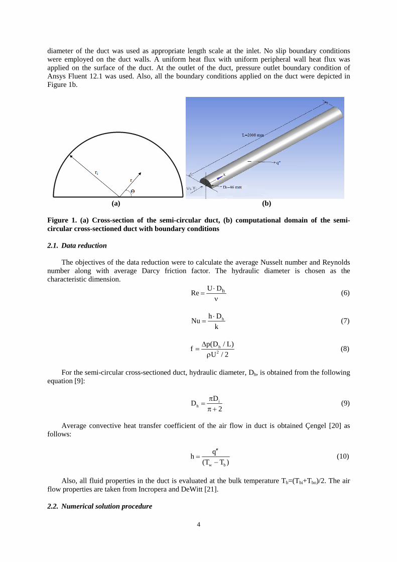
A schematic diagram depicting the cross section of the duct and computational domain of the
semi-circular cross-sectioned duct along with the coordinate system and dimensions of the flow geometry were presented in Figure 1a and b. Semi-circular cross-sectioned duct was mathematically modeled for numerical computations. The principle flow is in the x-direction. Turbulent flow enters the duct with a uniform velocity and temperature profile. The three-dimensional Navier-Stokes, energy and turbulence equations are used to describe the flow and heat transfer in the computational domains. The three-dimensional incompressible Newtonian flow with negligible buoyancy effects and viscous dissipation has been regarded as turbulent and steady. The physical properties of fluid, taken at the bulk temperature, have been considered to be constant in the duct.
The continuity, momentum and energy equations in cylindrical coordinate system are given as
(a) Continuity Equation:
u 1 (rv) 1 w 0x r r r
∂ ∂ ∂+ + =
∂ ∂ ∂θ (1)
(b) Axial Momentum Equation:
2 2
2 2 2u u w u p u 1 u 1 uu v rx r r x r r rx r
∂ ∂ ∂ ∂ ∂ ∂ ∂ ∂ ρ + + = − + µ + + ∂ ∂ ∂θ ∂ ∂ ∂∂ ∂θ (2)
(b) Radial Momentum Equation:
( )2 2 2
2 2 2 2v v w v w p v 1 1 v 2 wu v rvx r r r r r r rx r r
∂ ∂ ∂ ∂ ∂ ∂ ∂ ∂ ∂ ρ + + − = − + µ + + − ∂ ∂ ∂θ ∂ ∂ ∂ ∂θ∂ ∂θ (3)
(c) Angular Momentum Equation:
( )2 2
2 2 2 2w w w w vw 1 p w 1 1 w 2 vu v rwx r r r r r r rx r r
∂ ∂ ∂ ∂ ∂ ∂ ∂ ∂ ∂ ρ + + + = − + µ + + + ∂ ∂ ∂θ ∂θ ∂ ∂ ∂θ∂ ∂θ (4)
(d) Energy Equation:
22 2
p p p 2 2 2
22 2 2 2
e2
T T w T T k T k T uc u c v c k r 2x r r r r r xx r
v 2 w w 1 u u v 1 v w2 v r Gr x r r x r r rr
∂ ∂ ∂ ∂ ∂ ∂ ∂ ∂ ρ + ρ + ρ = + + + µ ∂ ∂ ∂θ ∂ ∂ ∂∂ ∂θ
∂ µ ∂ ∂ ∂ ∂ ∂ ∂ ∂ + µ + + + µ + + µ + + µ + + ∂ ∂θ ∂ ∂θ ∂ ∂ ∂θ ∂
(5)
The continuity, momentum, energy and turbulence equations were solved by using Ansys Fluent
12.1. The fluid enters the duct with uniform velocity and temperature profile. Turbulence intensity levels used at the inlet of the duct varied from 4 to 5 % depending on the Reynolds number. Hydraulic
4
diameter of the duct was used as appropriate length scale at the inlet. No slip boundary conditions were employed on the duct walls. A uniform heat flux with uniform peripheral wall heat flux was applied on the surface of the duct. At the outlet of the duct, pressure outlet boundary condition of Ansys Fluent 12.1 was used. Also, all the boundary conditions applied on the duct were depicted in Figure 1b.
(a) (b) Figure 1. (a) Cross-section of the semi-circular duct, (b) computational domain of the semi-circular cross-sectioned duct with boundary conditions
2.1. Data reduction
The objectives of the data reduction were to calculate the average Nusselt number and Reynolds
number along with average Darcy friction factor. The hydraulic diameter is chosen as the characteristic dimension.
hU DRe ⋅=
ν (6)
hh DNu
k⋅
= (7)
h
2
p(D / L)fU / 2
∆=
ρ (8)
For the semi-circular cross-sectioned duct, hydraulic diameter, Dh, is obtained from the following
equation [9]:
ih
DD2
π=
π + (9)
Average convective heat transfer coefficient of the air flow in duct is obtained Çengel [20] as
follows:
w b
qh(T T )
′′=
− (10)
Also, all fluid properties in the duct is evaluated at the bulk temperature Tb=(Tbi+Tbo)/2. The air
flow properties are taken from Incropera and DeWitt [21]. 2.2. Numerical solution procedure
5
In this study, a general purpose finite-volume based commercial CFD software package Ansys
Fluent 12.1 has been used to carry out the numerical study. The code provides mesh flexibility by structured and unstructured meshes. Also, Ansys Fluent 12.1 includes several turbulence models.
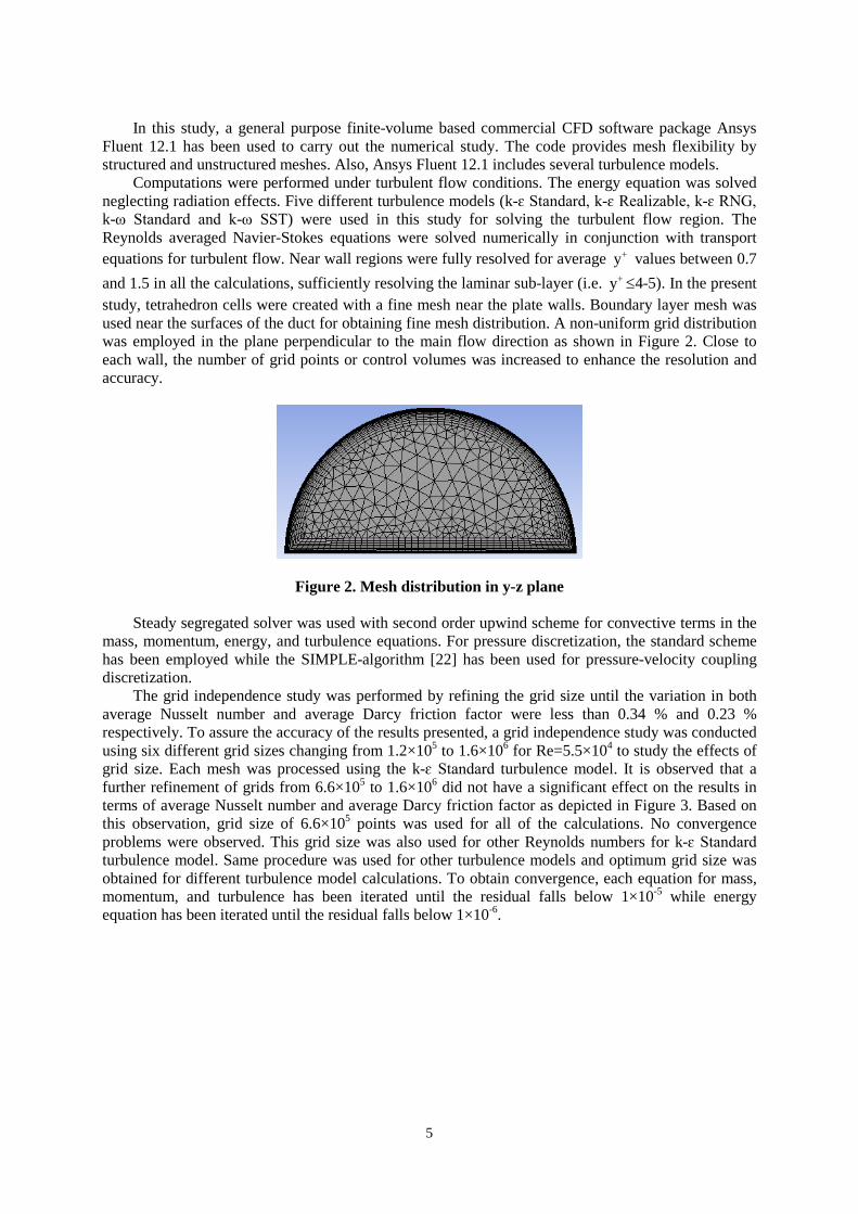
Computations were performed under turbulent flow conditions. The energy equation was solved neglecting radiation effects. Five different turbulence models (k-ɛ Standard, k-ɛ Realizable, k-ɛ RNG, k-ω Standard and k-ω SST) were used in this study for solving the turbulent flow region. The Reynolds averaged Navier-Stokes equations were solved numerically in conjunction with transport equations for turbulent flow. Near wall regions were fully resolved for average y+ values between 0.7 and 1.5 in all the calculations, sufficiently resolving the laminar sub-layer (i.e. y+ ≤4-5). In the present study, tetrahedron cells were created with a fine mesh near the plate walls. Boundary layer mesh was used near the surfaces of the duct for obtaining fine mesh distribution. A non-uniform grid distribution was employed in the plane perpendicular to the main flow direction as shown in Figure 2. Close to each wall, the number of grid points or control volumes was increased to enhance the resolution and accuracy.
Figure 2. Mesh distribution in y-z plane Steady segregated solver was used with second order upwind scheme for convective terms in the
mass, momentum, energy, and turbulence equations. For pressure discretization, the standard scheme has been employed while the SIMPLE-algorithm [22] has been used for pressure-velocity coupling discretization.
The grid independence study was performed by refining the grid size until the variation in both average Nusselt number and average Darcy friction factor were less than 0.34 % and 0.23 % respectively. To assure the accuracy of the results presented, a grid independence study was conducted using six different grid sizes changing from 1.2×10⁵ to 1.6×10⁶ for Re=5.5×10⁴ to study the effects of grid size. Each mesh was processed using the k-ɛ Standard turbulence model. It is observed that a further refinement of grids from 6.6×10⁵ to 1.6×10⁶ did not have a significant effect on the results in terms of average Nusselt number and average Darcy friction factor as depicted in Figure 3. Based on this observation, grid size of 6.6×10⁵ points was used for all of the calculations. No convergence problems were observed. This grid size was also used for other Reynolds numbers for k-ɛ Standard turbulence model. Same procedure was used for other turbulence models and optimum grid size was obtained for different turbulence model calculations. To obtain convergence, each equation for mass, momentum, and turbulence has been iterated until the residual falls below 1×10⁻⁵ while energy equation has been iterated until the residual falls below 1×10⁻⁶.

6
Grid Size
2,0x10⁵ 4,0x10⁵ 6,0x10⁵ 8,0x10⁵ 106 1,2x10⁶ 1,4x10⁶ 1,6x10⁶
Nu
110
112
114
116
118
120
122
f*50
00
110
112
114
116
118
120
122
Nu f
Figure 3. Grid size effect for average Nusselt number and average Darcy friction factor for k-ɛ Standard turbulence model 3. Results and Discussion
In the study reported here, the convective heat transfer and fluid friction in an air-cooled semi-
circular cross-sectioned duct under uniform surface heat flux with uniform peripheral wall heat flux was numerically investigated. The investigation was carried out under hydrodynamically and thermally developing turbulent flow conditions. The results were presented in non-dimensional Nusselt number and Darcy friction factor. After the determination of temperature fields in the fluid, the average Nusselt numbers were calculated. In addition, average Darcy friction factors were estimated with the determination of pressure drop in the duct. Numerical results obtained under steady-state conditions were presented in Figure 4 through Figure 16 and Table 1. Plotted in these figures were the best-fit lines. The flow velocity and temperature distributions, average Nusselt numbers and average Darcy friction factors were presented in this study to highlight the influence of duct geometry and wall boundary conditions on thermal performance of semi-circular channel and provide additional useful design data.
Air at the ambient temperature entered the duct with uniform velocity profile. The surface of the duct was kept at constant heat flux condition. It is useful to start with the discussion of global features of the air flow in the duct. Figure 4 shows that the velocity contours at the outlet of the duct for k-ɛ RNG turbulence model and different Reynolds numbers. It is seen in this figure that velocity profile doesn’t change greatly with changing Reynolds numbers and maximum velocity is at the center of the duct.
Figure 4. Isovel contours of velocity magnitude at the outlet of the duct for different Reynolds numbers
Temperature contours at the outlet of the duct for k-ɛ RNG turbulence model and different
Reynolds numbers are shown in Figure 5. Temperature contours have almost same profile for different Reynolds numbers. Also, temperature decreases gradually towards to center of the duct from the surface. Minimum temperature is at the center of the duct.

7
Figure 5. Temperature contours at the outlet of the duct for different Reynolds numbers
Velocity and temperature contours at the outlet of the duct for Re=5.5×10⁴ and different
turbulence models were presented in Figure 6 and Figure 7, respectively. It is obtained in the figures that there are no big differences in the velocity and temperature profiles for different turbulence models.
Figure 6. Isovel contours of velocity magnitude at the outlet of the duct for different turbulence models
Figure 7. Temperature contours at the outlet of the duct for different turbulence models
Figure 8 and Figure 9 shows that the velocity and temperature distributions for different axial
stations in the duct at Re=5.5x10⁴. The figures represent the hydrodynamically and thermally developing flow in the semi-circular cross-sectioned duct. Also, it is seen that the velocity and temperature distributions don’t change nearly after x=0.75 m.

8
Figure 8. Isovel contours of velocity magnitude for different axial stations
Figure 9. Temperature contours for different axial stations
The velocity and temperature distributions at x=0.5 m for different Reynolds number were given in Figure 10 and Figure 11, respectively. Figures represent the variation of the velocity and temperature distributions in the entrance region of the duct with Reynolds number; however, it is seen in Figure 4 and Figure 5, velocity and temperature profiles don’t change greatly with changing Reynolds numbers at the outlet of the duct. This case shows that the profiles of velocity and temperature aren’t influenced with changing Reynolds number in the hydrodynamically and thermally fully developed region, but are influenced with changing Reynolds numbers in the entrance region.
Figure 10. Isovel contours of velocity magnitude for different Reynolds numbers

9
Figure 11. Temperature contours for different Reynolds numbers
Figure 12 and Figure 13 give the velocity and temperature distributions at x=0.5 m and Re=5.5x10⁴ for different turbulence models. It is seen in these figures that the profiles of velocity and temperature change with variation of turbulence models; however, it can be seen in Figure 6 and Figure 7, there are no big differences in the velocity and temperature profiles for different turbulence models at the outlet of the duct. This case indicates that the profiles of velocity and temperature change with changing turbulence models in the entrance region of the duct, but don’t change in the hydrodynamically and thermally fully developed region.
Figure 12. Isovel contours of velocity magnitude for different turbulence models
Figure 13. Temperature contours for different turbulence models
In order to show that whether the flow is hydrodynamically fully developed in the duct, typical velocity profiles on the plane at r=0 m. for different location of the duct are shown in Figure 14a for Re=5.5×10⁴ and k-ɛ RNG turbulence model. As can be seen from Figure 14a, the velocity magnitude profile at different location along x-direction in the semi-circular cross-sectioned duct was plotted as a function of the dimensionless height (r/ri) of the duct. In the fully developed region, the velocity

10
profile repeated itself at various positions along the duct. As it can be seen from Figure 14a, velocity distribution reaches hydrodynamically fully developed flow condition nearly at x=0.75 m.
The temperature distribution continuously changes along the duct and one can think of that a thermally fully developed condition could never be reached. This situation is reconciled by working with the dimensionless form of the temperature [2]. Dimensionless temperature profile is defined as Θ=(T(x,y,z)-Ti)/( q′′ Dh/k) for uniform surface heat flux. Dimensionless temperature distribution was plotted as function of the dimensionless height (r/ri) of the duct for various positions along the duct on the plane at r=0 m. in Figure 14b for Re=5.5×10⁴ and k-ɛ RNG turbulence model. It is clearly obtained that dimensionless temperature distribution reaches thermally fully developed condition nearly at x=0.75 m.
Velocity Magnitude (m/s)
0 10 20 30
r/ri
0,0
0,2
0,4
0,6
0,8
1,0
1,2
x=0.25 m.x=0.75 m. x=1.0 m.
a
Dimensionless Temperature
0,0 0,2 0,4 0,6 0,8 1,0
r/ri
0,0
0,2
0,4
0,6
0,8
1,0
1,2
x=0.25 m.x=0.75 m.x=1.0 m.
b
Figure 14. (a) Velocity and (b) dimensionless temperature distributions for different location along the duct
One of the key parameters of interest in the hydrodynamic and thermal entrance region is the
variation of local Darcy friction factor and local heat transfer coefficient using k-ɛ RNG turbulence model along the axial position. Figure 15a and 15b show these variations as function of dimensionless position (x/Dh) for the channel. Figure 15a shows the local Darcy friction factor as a function of dimensionless position (x/Dh) for different Reynolds number. It is obtained in this figure that local Darcy friction factor in the entrance is larger than the outlet of the duct for all Reynolds number. It is critical important key parameter of interest in the duct for the pressure drop in the main flow direction. An inspection of Figure 15b reveals that the values of local heat transfer coefficient in the inlet of the duct is much larger than those at the outlet section of the duct for various Reynolds number. This explains the critical importance of the thermal entrance region. Also it is obtained that, the local Darcy friction factor and the local heat transfer coefficient results repeated themselves along the duct, respectively. Hence, it is obtained that flow reaches hydrodynamically and thermally fully developed condition nearly at x/Dh=30.

11
x/Dh
10 30 50 700 20 40 60
f x
0,004
0,006
0,008
0,010
0,012
Re=1.5x10⁴
Re=3.5x10⁴
Re=5.5x10⁴
a
x/Dh
10 30 50 700 20 40 60
h x
50
100
150
200
250
Re=1.5x10⁴
Re=3.5x10⁴
Re=5.5x10⁴
b
Figure 15. (a) Local Darcy friction factor and (b) local heat transfer coefficient, as function of dimensionless position (x/Dh)
Numerically obtained average Nusselt numbers and average Darcy friction factors are expressed
as a power law variation with Reynolds number. In other words, results are presented in the forms of Nu=aReb and f=cRed. The average Nusselt number, average Darcy friction factor, and Reynolds number for flow in this duct are based on the hydraulic diameter Dh. The equations were obtained with least-square method for average Nusselt number and average Darcy friction factor. The values of a, b, c and d for Nu=aReb and f=cRed are given in Table 1. Table 1. Values of a, b, c and d for Nu=aReb and f=cRed
k-ɛ Standard
k-ɛ Realizable k-ɛ RNG k-ω
Standard k-ω SST
Nu a 0.0190 0.0185 0.0204 0.0171 0.0151 b 0.8 0.8 0.8 0.8 0.8
f c 0.3799 0.3764 0.3776 0.3360 0.3163 d -0.26 -0.26 -0.26 -0.26 -0.26
Figure 16a and 16b display the present numerical values of the average Nusselt number and
average Darcy friction factor with the experimental data obtained in the literature for turbulent flow condition where Re=1×10⁴<Re<5.5×10⁴. The k-ɛ Standard, k-ɛ Realizable, k-ɛ RNG, k-ω Standard and k-ω SST turbulence models were used in numerical studies. The results have shown that as the Reynolds number increases, heat transfer coefficient increases. In addition, Darcy friction factor decreases with increasing the Reynolds number. The numerical results for k-ɛ Standard, k-ɛ Realizable and k-ɛ RNG turbulence models are almost closer to each other and larger than numerical results of the k-ω Standard and k-ω SST turbulence models. Also it is seen that, k-ɛ Standard, k-ɛ Realizable and k-ɛ RNG turbulence models represent the literature results very well for average Nusselt number and average Darcy friction factor.

12
Re
15000 20000 25000 30000 40000 50000 6000010000
Nu
202530
405060
80
150
200250300
400
100
Nuk-ε Standard Nuk-ε Realizable Nuk-ε RNG Nuk-ω StandardNuk-ω SSTBerbish et al. [5]Gnielinski [23] Dittus and Boelter [24]
a
Re
15000 20000 25000 30000 40000 50000 6000010000
f
0,015
0,02
0,025
0,03
0,04
0,05
0,06
0,070,08
fk-ε Standard fk-ε Realizable fk-ε RNG f k-ω Standard f k-ω SSTBerbish et al. [5]Petukhov [25]
b
Figure 16. The changing of (a) average Nusselt number and (b) average Darcy friction factor; with Reynolds number 4. Conclusions
Heat transfer and fluid friction for hydrodynamically and thermally developing three-dimensional
steady turbulent flow in a horizontal semi-circular cross-sectioned duct was numerically investigated with the Reynolds number ranging from 1×10⁴ to 5.5×10⁴ for Pr≅0.7. The turbulence models used in numerical simulations are k-ɛ Standard, k-ɛ Realizable, k-ɛ RNG, k-ω Standard and k-ω SST. Results were given in Table 1, and in Figure 4 to Figure 16. It is observed that the numerical results for different turbulence models are harmonious with each other and the literature. The results of numerical computations are presented in terms of average Nusselt numbers and average Darcy friction factors. It is shown that increasing the Reynolds number increases the average Nusselt number. On the other hand, average Darcy friction factor decreases with increasing Reynolds number. Based on the present numerical solutions of full 3D governing equations of turbulent flow in the hydrodynamic and thermal entrance region, new engineering correlations are presented for the average Nusselt number and average Darcy friction factor in the form of Nu=aReb and f=cRed, respectively. For turbulent flow condition in hydrodynamic and thermal entrance region, the friction and heat transfer coefficients depend on the duct geometry and Reynolds number. Isovel contours of velocity magnitude and temperature distribution for different Reynolds numbers, turbulence models and axial stations in the duct were presented graphically. Also, local heat transfer coefficient and local Darcy friction factor as function of dimensionless position along the duct were obtained and given graphically in this investigation. It is observed that, flow reaches hydrodynamically and thermally fully developed condition nearly at x/Dh=30. The numerical results for different turbulence models were compared with each other and similar experimental investigations carried out in the literature. Finally it is obtained that, k-ɛ Standard, k-ɛ Realizable and k-ɛ RNG turbulence models are the most suitable turbulence models for this investigation.
Nomenclature
a, b, c, d constant coefficients for Nu=aReb and f=cRed, [-] cp specific heat, [Jkg-1K-1] Dh hydraulic diameter of the passageway through the considered semi-circular cross-
sectioned duct, [m] Di inner diameter of the duct, [m] f average Darcy friction factor, [-] fx local Darcy friction factor, [-] Ge energy generation rate per unit volume, [Wm-3] h average heat transfer coefficient in the duct, [Wm-2K-1] hx local heat transfer coefficient, [Wm-2K-1]

13
k thermal conductivity of air, [Wm-1K-1] L axial length of the duct, [m] Nu average Nusselt number for the steady state heat transfer in the duct, [-] ∆p pressure drop along the duct, [Pa] p pressure, [Pa] Pr Prandtl number for the air flowing through the duct, [-] q′′ steady-state rate of convective heat flux, [Wm-2] Re hydraulic diameter based Reynolds number of the air flow, [-] ri inner radius of the duct, [m] T fluid temperature, [K] Tb mean bulk temperature of the air flow in the duct, [K] Tbi, Tbo mean bulk temperature of the air flow at the inlet and outlet of the duct, respectively,
[K] Tw surface temperature of the duct, [K] Ti inlet air temperature, [K] U mean velocity of the air flow in the semi-circular cross-sectioned duct, [ms-1] Ui inlet air velocity, [ms-1] u, v, w velocity vectors in cylindrical coordinates, [ms-1] x, r, ϴ cylindrical coordinates, [-] Greek symbols Θ dimensionless temperature profile, [-] ν kinematic viscosity of air, [m2s-1] μ dynamic viscosity of air, [Nsm-2] ρ density of the air, [kgm-3] References [1] Shah, R. K. and London, A. L., Laminar Flow Forced Convection in Ducts, Academic Press
Inc., New York, USA, 1978, pp. 256-259. [2] Kakaç, S., Shah, R. K. and Aung, W., Handbook of Single-Phase Convective Heat Transfer,
John Wiley and Sons, USA, 1987, Chapter 3, pp. 4. [3] Kakaç, S. and Liu, H., Heat Exchangers Selection, Rating, and Thermal Design, 2nd ed., CRC
Press, USA, 2002, pp. 81-127. [4] Eckert, E. R. G., Irvine, T. F. J. and Yen, T. J., Local Laminar Heat Transfer in Wedge-Shaped
Passages, Transactions of the American Society of Mechanical Engineers, 80 (1958), pp. 1433-1438.
[5] Berbish, N. S., Moawed, M., Ammar, M. and Afifi, R. I., Heat Transfer and Friction Factor of Turbulent Flow through a Horizontal Semi-Circular Duct, Heat and Mass Transfer, 47 (2011), pp. 377-384.
[6] Hong, S. W. and Bergles, A. E., Laminar Flow Heat Transfer in the Entrance Region of Semi-Circular Ducts with Uniform Heat Flux, International Journal of Heat and Mass Transfer, 19 (1976), pp.123-124.
[7] Manglik, R. M. and Bergles, A. E., Laminar Flow Heat Transfer in a Semi-Circular Duct with Uniform Wall Temperature, International Journal of Heat and Mass Transfer, 31 (1988), pp.625-636.
[8] Zhang, H. Y. and Ebadian, M. A., Convective-Radiative Heat Transfer in the Thermal Entrance Region of the Semi-Circular Duct with Stream Wise Internal Fins, International Journal of Heat and Mass Transfer, 34 (1991), 12, pp. 3135-3142.
[9] Zhang, H. Y. and Ebadian, M. A., Heat Transfer in the Entrance Region of Semi-Circular Ducts with Internal Fins, Journal of Thermophysics and Heat Transfer, 6 (1992), pp. 296-301.

14
[10] Yang G, Ebadian M. A., Combined Radiation and Convection Heat Transfer in Simultaneously Developing Flow in Ducts With Semi-Circular and Right Triangular Cross Sections, Heat and Mass Transfer, 27 (1992), 3, pp. 141-148.
[11] Etemad, S. G., Laminar Heat Transfer to Viscous Nonnewtonian Fluids in Non-Circular Ducts, Ph. D. thesis, Mc-Gill University, Montreal, Canada, 1995.
[12] Etemad, S. G., Mujumdar, A. S. and Nassef, R., Viscous Nonnewtonian Forced Convection Heat Transfer in Semi-Circular and Equilateral Triangular Ducts: an Experimental Study, International Communications of Heat and Mass Transfer, 24 (1997), 5, pp. 609-620.
[13] Dong, Z. F. and Ebadian, M. A., Analysis of Combined Natural and Forced Convection in Vertical Semi-Circular Ducts with Radial Internal Fins, Numerical Heat Transfer Part A, 27 (1995), 3, 359-372.
[14] Busedra, A. A. and Soliman, H. M., Experimental Investigation of Laminar Mixed Convection in an Inclined Semi-Circular Duct under Buoyancy Assisted and Opposed Conditions, International Journal of Heat and Mass Transfer, 43 (2000), 7, pp. 1103-1111.
[15] Busedra, A. A. and Soliman, H. M., Analysis of Laminar Mixed Convection in Inclined Semi-Circular Ducts under Buoyancy Assisted and Opposed Conditions, Numerical Heat Transfer Part A, 36 (1999), pp. 527-544.
[16] Hakan, F. and Oztop, H. F., Effective Parameters on Second Law Analysis for Semi-Circular Ducts in Laminar Flow and Constant Wall Heat Flux, International Communications of Heat and Mass Transfer, 32 (2005), 1-2, pp. 266-274.
[17] Geyer, P. E., Fletcher, D. F. and Haynes, B. S., Laminar Flow and Heat Transfer in a Periodic Trapezoidal Channel with Semi-Circular Cross-Section, International Journal of Heat and Mass Transfer, 50 (2007), 17-18, pp. 3471-3480.
[18] Lei, Q. M. and Trupp, A. C., Experimental Study of Laminar Mixed Convection in the Entrance Region of a Horizontal Semi-Circular Duct, International Journal of Heat and Mass Transfer, 34 (1991), 9, pp. 2361-2372.
[19] Hasaidi, Y. M. F. El., Busedra, A. A. and Rustum, I. M., Laminar Mixed Convection in the Entrance Region of Horizontal Semicircular Ducts with the Flat Wall at the Top, ASME Journal of Heat Transfer, 129 (2007), 9, pp. 1203-1211.
[20] Çengel, Y. A., Heat Transfer a Practical Approach, McGraw-Hill, USA, 1998, pp. 372-380. [21] Incropera, F. P. and DeWitt, D. P., Fundamentals of Heat and Mass Transfer, 5th ed., John
Wiley and Sons, USA, 2002, pp. 917. [22] Patankar, S. V., Numerical Heat Transfer and Fluid Flow, Hemisphere Publishing Corporation,
USA, 1980, pp. 126-131. [23] Gnielinski, V., New Equations for Heat and Mass Transfer in Turbulent Pipe and Channel Flow,
International Chemical Engineering, 16 (1976), pp. 359-368. [24] Dittus, P. W. and Boelter, L. M. K., Heat Transfer in Automobile Radiators of the Tubular
Type, International Communications of Heat and Mass Transfer, 12 (1985), pp. 3-22. [25] Petukhov, B. S., in Irvine T. F. and Hartnett J. P., Advances in Heat Transfer, Academic Press,
New York, USA, 1970, Vol. 6.