
Method 6010D: Inductively Coupled Plasma Optical Emission ...
359
Pure Appl. Chem., Vol. 77, No. 2, pp. 359–372, 2005.DOI: 10.1351/pac200577020359© 2005 IUPAC
Three-dimensional modeling of inductivelycoupled plasma torches*
D. Bernardi, V. Colombo‡, E. Ghedini, and A. Mentrelli
Dipartimento di Ingegneria delle Costruzioni Meccaniche, Nucleari, Aeronautiche edi Metallurgia (DIEM) and Centro Interdipartimentale di Ricerca per le Applicazionidella Matematica (CIRAM), Università di Bologna, Bologna, Italy
Abstract: A 3D model for the simulation of inductively coupled plasma torches (ICPTs)working at atmospheric pressure is presented, using a customized version of the computa-tional fluid dynamics (CFD) commercial code FLUENT®. The induction coil is taken intoaccount in its actual 3D shape, showing the effects on the plasma discharge of removing theaxisymmetric hypothesis of simplification, which characterizes 2D approaches. Steady flowand energy equations are solved for optically thin argon plasmas under the assumptions oflocal thermodynamic equilibrium (LTE) and laminar flow. The electromagnetic field equa-tions are solved on an extended grid in the vector potential form. In order to evaluate the im-portance of various 3D effects on calculated plasma temperature and velocity fields, com-parisons of our new results with the ones obtainable from 2D models and from an improved2D model that includes 3D coil effects are presented. 3D results are shown for torches work-ing under various geometric and operating conditions and with different coil shapes, includ-ing conventional helicoidal, as well as planar, elliptical, and double-stage configurations.
Keywords: plasma torches; plasma simulation; high-frequency; rf discharges.
INTRODUCTION
In recent years, inductively coupled plasma torches (ICPTs) have played an increasing important rolein many technological processes, as a clean and effective means to produce plasma jets with high en-thalpy content that can be usefully employed in a wide range of applications, such as plasma spray dep-osition of materials, densification and spheroidization of powders, chemical synthesis of nanoparticles,waste treatment, and others [1]. Since the success of a given process depends directly on the plasmatemperature and velocity fields in the discharge and/or in the jet, which in turn depend on the geomet-ric and operating parameters of the system, the characterization of the torch and the knowledge of theinfluence of such parameters on the plasma properties is of primary importance. However, the detaileddiagnostics of ICPTs are very hard to perform, owing to the high temperatures involved and to the dif-ficulty of reaching the internal zones of the device without perturbing the discharge. As an alternative,mathematical modeling represents a valid and powerful tool to predict the characteristics of this kind ofsystem, also owing to the relevant progress recently made in computer technology, which allows for theimplementation of more and more sophisticated modeling approaches. In this frame, various 2D mod-els have been proposed in the past by different authors [2–10], to simulate the physical behavior of theplasma in ICPTs, also using an extended grid approach [5–10] for the description of the electromag-
*Paper based on a presentation at the 16th International Symposium on Plasma Chemistry (ISPC-16), Taormina, Italy, 22–27 June2003. Other presentations are published in this issue, pp. 345–495.‡Corresponding author

netic field. However, as all of these models assume the torch to be axisymmetric, important 3D effectsowing to the actual shape of the induction coil or to the nonaxisymmetric distribution of the inletgases, could not be revealed. Moreover, 2D models do not permit the study of torches with noncircu-lar cross-section. A first step in trying to highlight some of the 3D effects caused by the typical heli-coidal shape of the coil was the work of Xue et al. [10], which took into account within a 2D model-ing also the axial component of the induction current flowing with a given inclination angle throughan idealized concentric cylinder coil. In that paper, the authors showed that, although the impact onthe calculated plasma temperature is negligible, some swirling effects arise in the plasma flow as aconsequence of the Lorentz force induced by the axial and radial components of the electric and mag-netic fields, respectively. A 3D simulation of the gas mixing in the downstream region of an ICPT wasalso performed by Mostaghimi et al. [11], but limiting the computational domain to a region that didnot include the induction coil and its electromagnetic effects. In order to obtain a more realistic de-scription of ICPTs, a fully 3D model [12–15], which completely removes the assumption of axi-symmetry, has been recently developed. The model has been implemented in the framework of thecomputational fluid dynamics (CFD) commercial software FLUENT®, using a grid extending alsooutside the plasma region for the treatment of the electromagnetic field. A user-defined scalar (UDS)technique [9] has been adopted to suitably customize the basic FLUENT code in order to addMaxwell’s equations to its built-in fluid dynamic module. In this work, simulation results obtained bymeans of the 3D model will be presented for different coil shapes (including conventional helicoidalas well as planar, elliptical, and double-stage configurations), torch geometries, and operating condi-tions and compared, when possible, to literature data or experimental observations. The calculationscarried out show that the geometric parameters of the coil (such as total axial length, inclination angleof the coil turns, shape of the coil endings) play a major role in determining nonaxisymmetric behav-iors of the plasma discharge which should be taken into account in the design stage of the system inorder to avoid undesired effects, such as hot spot formations on the tube wall or losses at the wall ofthe confinement tube of material injected in the plasma.
MODELING APPROACH
Governing equations
The physical behavior of the plasma is modeled, removing the axisymmetric assumption that has beenextensively used in most of the previous studies concerning ICPTs. This leads to a fully 3D model,which has been implemented in the FLUENT environment. The following assumptions have been em-ployed:
• the flow is steady and laminar;• the plasma is optically thin and in local thermodynamic equilibrium (LTE);• the viscous dissipation term in the energy equation is neglected; and• the displacement currents are neglected.
The equations for the transport of mass, momentum, and energy are written as follows:
• conservation of mass:
∇ � (ρu) = 0 (1)
• conservation of momentum:
(2)
D. BERNARDI et al.
© 2005 IUPAC, Pure and Applied Chemistry 77, 359–372
360
∇ ( ) = −∇ + ∇ ∇ ∇( ) − ∇ ( )
+ +⋅ ⋅ ⋅ρ µ µ ρuu u + u up IT 2
3g JJ B×

• conservation of energy:
(3)
where ρ is the plasma density, p is the pressure, h is the enthalpy, T is the temperature, u is the veloc-ity, k is the thermal conductivity, cp is the specific heat at constant pressure, µ is the viscosity, g is thegravitational force, E is the electric field, B is the magnetic induction, J is the current density inducedin the plasma, and R is the volumetric radiative loss.
The electromagnetic field generated by the current flowing in the coil (Jcoil) and by the inducedcurrents in the plasma (J) can be described by means of Maxwell’s equations written in their vector po-tential formulation:
∇2A – iωµoσA + µoJcoil = 0 (4)
where µο is the magnetic permeability of the free space (4π�10–7 H/m), σ is the plasma electrical con-ductivity, and ω = 2πf, f being the frequency of the electromagnetic field. In this work, we have usedthe simplified Ohm’s law J = σE as suggested in [16]. The electric field E and the magnetic field Bwhich appear in eqs. 2 and 3 are obtained from the vector potential A with the following expressions:E = –iωA, B = ∇ × A.
Boundary conditions
Boundary conditions for the conservation equations of mass (eq. 1), momentum (eq. 2), and energy(eq. 3) are the following: on the inner wall of the confinement tube, the no-slip condition was imposed,while on the outer wall of the confinement tube a fixed temperature value of 300 K is imposed. At thetorch inlet, uniform velocity profiles of gas (calculated on the basis of the given flow rates) are assumed.At the torch exit, the FLUENT outflow condition (which corresponds to a fully developed flow condi-tion [17]) was adopted. Equation 4 is solved in a domain extending also outside the torch region, usingvanishing boundary conditions for the vector potential [5,9].
Computational procedure
The governing equations for the conservation of mass (eq. 1), momentum (eq. 2) and energy (eq. 3) aresolved by the FLUENT solver on an unstructured grid extending inside the torch region and the con-finement tube, while the electromagnetic field equation (eq. 4) is solved by the FLUENT solver, with aUDS approach, in a domain extending also outside the torch region, in order to apply the vanishingboundary conditions for the vector potential, as previously explained in [5,9]. The computational gridis a hybrid one composed by tetrahedrons, hexahedrons, and wedges, and it is built by means of theGAMBIT® software package and then imported into the FLUENT environment. The approximatenumber of cells composing the grid is 4.5�105 (slightly varying depending on the torch and coil con-figuration). Simulations have mainly been carried out on a cluster of workstations, i.e., splitting up thegrids and data in various partitions and then assigning each partition to a different compute process.
RESULTS
In the following, all the plasma fields concerning nonaxisymmetric coil shapes will refer to two per-pendicular planes passing through the axis of the torch, whose relative position is evidenced by coilview, while for axisymmetric configurations, the results are presented for one of the infinite identicalplanes passing through the axis of the torch.
© 2005 IUPAC, Pure and Applied Chemistry 77, 359–372
3D modeling of inductively coupled plasma torches 361
∇ ( ) = ∇ ∇
+ × −⋅ ⋅ρu J Eh
k
ch R
p

In order to test the code, numerical simulations have been performed within the 3D model for aTekna PL-50 torch geometry (Tekna Plasma Systems, Inc.) with dimensions and operating conditionsgiven in Fig. 1 and with the axisymmetric ring-shaped coil configuration shown in Fig. 2a.Corresponding results concerning plasma temperature and power density distributions are presented inFigs. 2b and 2c, which show a good agreement with standard 2D literature results [7,9]. As expected,the plasma fields reported in Figs. 2b and 2c are axisymmetric, as a result of the axisymmetry of bothcoil geometry and boundary conditions employed in the calculation.
In Fig. 3, another test case is considered for a torch configuration with the same dimensions andworking conditions of Fig. 1, but with an idealized cylindrical coil in which the electric current flowswith an inclination angle of 3.70° with respect to the horizontal plane (Fig. 3a). For this case, resultsobtained by means of the 3D model are presented in Figs. 3b, 3c, and 3d, showing plasma temperature,power density, and tangential velocity fields, respectively. These data can be qualitatively compared to
D. BERNARDI et al.
© 2005 IUPAC, Pure and Applied Chemistry 77, 359–372
362
Fig. 1 Tekna PL-50 plasma torch geometry.
Fig. 2 Test case: axisymmetric ring-shaped coil. (a) Schematic of the confinement tube and induction coil; (b)plasma temperature field [K]; (c) power dissipation [W/m3].

the ones obtained by Xue et al. [10] in the frame of an improved 2D model, taking into account also theaxial coil current component, for the same torch geometry and working conditions, but for a dischargepower of 25 kW. In particular, Fig. 3d shows that a swirl velocity component arises due to the tangen-tial Lorentz force generated by the axial component of the coil current, according to the results pre-sented in [10]. Plasma temperature and power density distributions of Figs. 3b and 3c differ from theones of Fig. 2 mainly due to the coil shape.
A more realistic coil configuration with 2.5 turns inclined of 6.60° with respect to the horizontalplane, is taken into account in Fig. 4a, for a torch with the same dimensions and operating conditionsof Fig. 1. In this case, the strong nonaxisymmetry of the coil leads to a significant displacement of theplasma discharge and to the formation of a hot spot in the confinement tube. This behavior is due to theunbalancing of the Lorentz forces in the radial direction, which overcome in magnitude the tangentialLorentz forces due to the axial component of the coil current, the main source of nonaxisymmetry beingthe coil shape and not the axial current component. The formation of a hot spot in the confinement tubemakes this coil configuration unsuitable for technological applications because of the risk of damagingthe tube wall in the absence of a swirl component for the sheath gas.
© 2005 IUPAC, Pure and Applied Chemistry 77, 359–372
3D modeling of inductively coupled plasma torches 363
Fig. 3 Test case: axisymmetric cylindrical coil. (a) Schematic of the confinement tube and induction coil; (b)plasma temperature field [K]; (c) power dissipation [W/m3]; (d) tangential velocity [m/s].

In Fig. 5, results concerning a coil configuration with 5 turns inclined of 3.68° with respect to thehorizontal plane are presented, for a discharge power of 25 kW. Torch dimensions and working para-meters that differ from those reported in Fig. 1 are summarized in Fig. 5a. Plasma temperature fieldsreported in Figs. 5b and 5c show the more axisymmetric behavior of the plasma discharge with respectto the 2.5 turns coil configuration, while Fig. 5d shows the arising of a swirl velocity component ofgreater order of magnitude than that obtained with the idealized cylindrical coil (Fig. 3d). It is worthnoting that, also in this case, the absence of a swirl component in the sheath gas may lead to undesiredhot spots in the confinement tube.
D. BERNARDI et al.
© 2005 IUPAC, Pure and Applied Chemistry 77, 359–372
364
Fig. 4 2.5 turns coil. (a) Schematic of the confinement tube and induction coil; (b) plasma temperature fields [K];(c) plasma and wall temperature fields [K] on three horizontal planes located at z = 60, 92, 200 mm, respectively,from bottom to top; (d) power dissipation [W/m3].
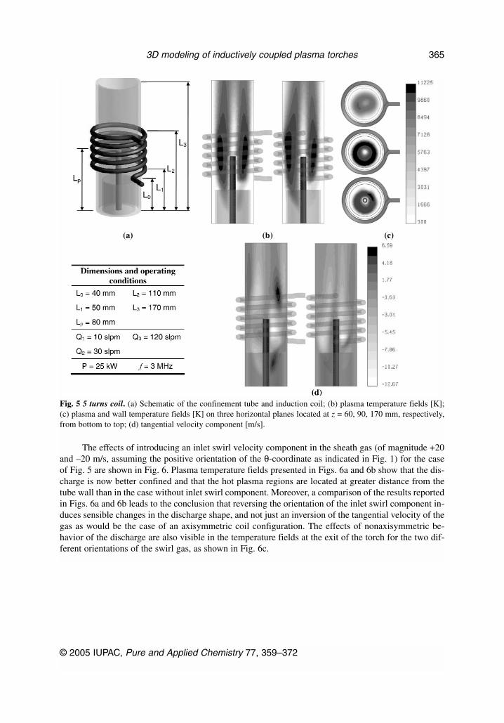
The effects of introducing an inlet swirl velocity component in the sheath gas (of magnitude +20and –20 m/s, assuming the positive orientation of the θ-coordinate as indicated in Fig. 1) for the caseof Fig. 5 are shown in Fig. 6. Plasma temperature fields presented in Figs. 6a and 6b show that the dis-charge is now better confined and that the hot plasma regions are located at greater distance from thetube wall than in the case without inlet swirl component. Moreover, a comparison of the results reportedin Figs. 6a and 6b leads to the conclusion that reversing the orientation of the inlet swirl component in-duces sensible changes in the discharge shape, and not just an inversion of the tangential velocity of thegas as would be the case of an axisymmetric coil configuration. The effects of nonaxisymmetric be-havior of the discharge are also visible in the temperature fields at the exit of the torch for the two dif-ferent orientations of the swirl gas, as shown in Fig. 6c.
© 2005 IUPAC, Pure and Applied Chemistry 77, 359–372
3D modeling of inductively coupled plasma torches 365
Fig. 5 5 turns coil. (a) Schematic of the confinement tube and induction coil; (b) plasma temperature fields [K];(c) plasma and wall temperature fields [K] on three horizontal planes located at z = 60, 90, 170 mm, respectively,from bottom to top; (d) tangential velocity component [m/s].

In Fig. 7, results are shown for a torch [18] designed for applications in atmospheric plasmaspraying of materials, which is here supposed to operate at a discharge power level of 6 kW. The slightnonaxisymmetry of the calculated plasma temperature field, which is mainly located in the regions cor-
D. BERNARDI et al.
© 2005 IUPAC, Pure and Applied Chemistry 77, 359–372
366
Fig. 6 5 turns coil with swirl gas. (a) plasma temperature fields [K] for vθ = 20 m/s; (b) plasma temperature fields[K] for vθ = −20 m/s; (c) plasma and wall temperature fields [K] at the torch exit for the case (a) and (b),respectively, from bottom to top.
Fig. 7 Plasma spraying torch. (a) Schematic of the confinement tube and induction coil; (b) dimensions andoperating conditions; (c) plasma temperature fields [K]; (d) power dissipation [W/m3].
responding to the first and last turns of the coil, as shown in Fig. 7c, is in qualitative good agreementwith the experimental measurements carried out in [18] by means of an enthalpy probe technique. Sincethere are many parameters affecting the spraying process both on the powder side (such as powder type,size, injection position) and on the plasma side (such as operating power, flow rates, gas type, coilshape), 3D modeling can be a useful tool in the design of such systems.
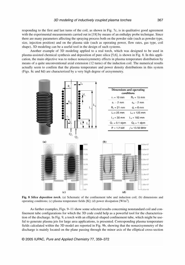
Another example of 3D modeling applied to a real torch, which was designed to be used inplasma-assisted chemical synthesis and deposition of pure silica [5,6], is shown in Fig. 8. In this appli-cation, the main objective was to reduce nonaxisymmetry effects in plasma temperature distribution bymeans of a quite unconventional axial extension (12 turns) of the induction coil. The numerical resultsactually seem to confirm that the plasma temperature and power density distributions in this system(Figs. 8c and 8d) are characterized by a very high degree of axisymmetry.
As further examples, Figs. 9–11 show some selected results concerning nonstandard coil and con-finement tube configurations for which the 3D code could help as a powerful tool for the characteriza-tion of the discharge. In Fig. 9, a torch with an elliptical-shaped confinement tube, which might be use-ful to generate plasma jets for large area applications, is presented. Corresponding plasma temperaturefields calculated within the 3D model are reported in Fig. 9b, showing that the nonaxisymmetry of thedischarge is mainly located on the plane passing through the minor axis of the elliptical cross-section
© 2005 IUPAC, Pure and Applied Chemistry 77, 359–372
3D modeling of inductively coupled plasma torches 367
Fig. 8 Silica deposition torch. (a) Schematic of the confinement tube and induction coil; (b) dimensions andoperating conditions; (c) plasma temperature fields [K]; (d) power dissipation [W/m3].

of the torch. This effect is also evidenced by the temperature fields on different horizontal planes, shownin Fig. 9c. In Fig. 10, a planar coil configuration is taken into account, as suggested in [19], in order toimprove the fluid dynamic characteristics of the plasma gas for the optimization of the chemicalprocesses inside the torch, avoiding material deposition on the tube wall. Finally, Fig. 11 shows some3D simulation results for a double-stage torch, first introduced by McKelliget [19] and than studied bysome of the authors in [20–23] within a 2D model. This configuration reveals some interesting features,such as the possibility of working with high gas flow rates and of having long residence times in a high-temperature plasma region for the injected particles (owing to the axially extended discharge, as shownin Fig. 11c) in order to obtain their complete melting.
D. BERNARDI et al.
© 2005 IUPAC, Pure and Applied Chemistry 77, 359–372
368
Fig. 9 Elliptical torch. (a) Schematic of the confinement tube and induction coil with dimensions and operatingconditions; (b) plasma temperature fields [K]; (c) plasma and wall temperature fields [K] on three horizontal planeslocated at z = 40, 70, 150 mm, respectively, from bottom to top.

© 2005 IUPAC, Pure and Applied Chemistry 77, 359–372
3D modeling of inductively coupled plasma torches 369
Fig. 10 Planar coil torch. (a) Schematic of the confinement tube; (b) induction coil with dimensions and operatingconditions; (c) plasma temperature fields [K].

CONCLUSIONS
The results presented in this paper show that 3D effects may arise in the ICPT’s discharge dependingmainly on the coil shape and play an important role in the physical characterization of this kind of de-vices. When only the axial component of induction coil current is taken into account, within an ax-isymmetric coil configuration, the effects on plasma temperature distribution are negligible, while mostimportant effects on nonaxisymmetry arise when the real induction coil shape is considered. The mainfeature of 3D modeling in ICPTs is the possibility of taking into account nonstandard coil and con-finement tube shapes in the design stage of this kind of device for a particular application, in order tooptimize the discharge characteristics, since the complexity of the phenomena involved inside this kindof device, especially for what concerns the fluid dynamics, let the results be quite difficult to foreseewhen changing torch operating parameters. For this reason, the 3D code can be a useful tool in the de-sign of ICPTs. For example, in plasma treatment of powders, it is possible to determine the coil shapeinfluence on temperature and velocity fields in the design stage of the process, in order to maximize thequality of the results (e.g., coating properties, ratio of spheroidization, and all of the parameters that de-pend upon the thermal history of the particles inside the plasma) and avoiding powder deposition on the
D. BERNARDI et al.
© 2005 IUPAC, Pure and Applied Chemistry 77, 359–372
370
Fig. 11 Double-stage RF–RF torch. (a) Schematic of the confinement tube and induction coil; (b) dimensions andoperating conditions; (c) plasma temperature fields [K]; (d) power dissipation [W/m3].

confinement tube wall. The next step in this research will be the setting up of a series of comparisonsbetween numerical and experimental results for different torch operating conditions and geometries, inorder to test and tune the code [24].
ACKNOWLEDGMENTS
This work was performed with partial financial support from the University of Bologna Goal-Orientedproject 2001–2003 and ex-60% 2001–2002 projects, from the Italian Ministry of Education, Universityand Scientific Research (M.I.U.R.) national project COFIN-2002 and from the National Group forMathematical Physics (G.N.F.M.) of the Italian Institute of High Mathematics.
REFERENCES
1. M. I. Boulos. High Temp. Mater. Proc. 1 (1), 17–39 (1997).2. J. Mostaghimi and M. I. Boulos. Plasma Chem. Plasma Process. 9 (1), 25–44 (1989).3. X. Chen and E. Pfender. Plasma Chem. Plasma Process. 11 (1), 103 (1991).4. P. Proulx, J. Mostaghimi, M. I. Boulos. Int. J. Heat Mass Transfer 34 (10), 2571–2579 (1991).5. V. Colombo, C. Panciatichi, A. Zazo, G. Cocito, L. Cognolato. IEEE Trans. Plasma Sci. 25 (5),
1073–1080 (1997). 6. C. Panciatichi, P. Cocito, M. C. N. De Leo. “Vitreous silica layers Synthesized by an inductively
coupled plasma torch (ICPT) working at atmospheric pressure: Deposition and characterization”,in Progress in Plasma Processing of Materials 1999, P. Fauchais and J. Amoroux (Eds.), pp.885–890, Begell House, New York (1999).
7. S. Xue, P. Proulx, M. I. Boulos. J. Phys. D: Appl. Phys. 34 (12), 1897–1906 (2001).8. M. I. Boulos. J. Visualization 4 (1), 19–28 (2001).9. D. Bernardi, V. Colombo, E. Ghedini, A. Mentrelli. Eur. Phys. J. D 27, 55–72 (2003).
10. S. Xue, P. Proulx, M. I. Boulos. Plasma Chem. Plasma Process. 23 (2), 245–263 (2002).11. Z. Njah, J. Mostaghimi, M. Boulos. Int. J. Heat Mass Transfer 36 (16), 3909–3919 (1993).12. D. Bernardi, V. Colombo, E. Ghedini, A. Mentrelli. Eur. Phys. J. D 22 (1), 119–125 (2003).13. D. Bernardi, V. Colombo, E. Ghedini, A. Mentrelli. Eur. Phys. J. D 25 (3), 271–277 (2003).14. D. Bernardi, V. Colombo, E. Ghedini, A. Mentrelli. Eur. Phys. J. D 25 (3), 279–285 (2003).15. D. Bernardi, V. Colombo, E. Ghedini, A. Mentrelli. “Three-dimensional effects in the design of
inductively coupled plasma torches”, in Atti del XVI Congresso dell’Associazione Italiana delVuoto, pp. 267–272, Editrice Compositori, Bologna (2003).
16. M. Mitchner and C. H. Krueger. Partially Ionized Gases, John Wiley, New York (1973).17. FLUENT© 6.1 User’s Guide, Fluent Inc., Lebanon, NH (2003).18. G. Nutsch. “Atmospheric induction plasma spraying”, in Progress in Plasma Processing of
Materials 2003, P. Fauchais (Ed.), pp. 401–408, Begell House, New York (2003).19. J. W. McKelliget and N. El-Kaddah. J. Appl. Phys. 64 (6), 2948 (1988).20. D. Bernardi, V. Colombo, G. G. M. Coppa, E. Ghedini, A. Mentrelli. “Numerical modelling of
RF-RF hybrid plasma torches and parametric study for various geometric, flow and electric con-figurations”, in Progress in Plasma Processing of Materials 2001, P. Fauchais (Ed.), pp. 339–346,Begell House, New York (2001).
21. D. Bernardi, V. Colombo, G. G. M. Coppa, E. Ghedini, A. Mentrelli. “Investigation on operatingconditions and efficiency optimization of RF-RF hybrid plasma torches”, in Progress in PlasmaProcessing of Materials 2001, P. Fauchais (Ed.), pp. 359–364, Begell House, New York (2001).
22. D. Bernardi, V. Colombo, G. G. M. Coppa, E. Ghedini, A. Mentrelli. High Temp. Mater. Proc. 7(1), 71–76 (2003).
© 2005 IUPAC, Pure and Applied Chemistry 77, 359–372
3D modeling of inductively coupled plasma torches 371

23. D. Bernardi, V. Colombo, E. Ghedini, A. Mentrelli. Eur. Phys. J. D 28 (3), 399–422 (2004).24. V. Colombo, G. Gao, E. Ghedini, J. Mostaghimi. “Asymmetry effects in the diagnostics and sim-
ulation of RF inductively coupled plasma torch”, in Proceedings of the 16th InternationalSymposium on Plasma Chemistry (ISPC-16), on CD-ROM (2003).
D. BERNARDI et al.
© 2005 IUPAC, Pure and Applied Chemistry 77, 359–372
372