Three-Dimensional Modeling and Analysis of Mechanized ...
18
Acta Polytechnica Hungarica Vol. 18, No. 4, 2021 – 213 – Three-Dimensional Modeling and Analysis of Mechanized Excavation for Tunnel Boring Machines Danial Mohammadzadeh S. 1,2,3,4 , Nader Karballaeezadeh 5 , Amirhossein Sanaei Zahed 4,6 , Amir Mosavi 7* , Felde Imre 7 1 Department of Civil Engineering, Ferdowsi University of Mashhad, Mashhad, University street 1, P.O. BOX 9177948974, Iran [email protected] 2 Department of Civil Engineering, Mashhad Branch, Islamic Azad University, Mashhad, University street 1, P.O. BOX 9187147578, Iran 3 Department of Civil Engineering, Faculty of Montazeri, Khorasan Razavi Branch, Technical and Vocational University (TVU), Mashhad, University street 1, P.O. BOX 9176994594, Iran 4 Department of Elite Relations with Industries, Khorasan Construction Engineering Organization, Mashhad, University street 1, P.O. BOX 9185816744, Iran 5 Faculty of Civil Engineering, Shahrood University of Technology, Shahrood, University blvd. 1, P.O. BOX 3619995161, Iran [email protected] 6 Toos Institite of Higher Education, Khorasan Razavi, Mashhad, University street 1, P.O. BOX 9188911111, Iran, [email protected] 7 John von Neumann Faculty of Informatics, Óbuda University, Bécsi út 96/b, H- 1034 Budapest, Hungary, [email protected], [email protected] Abstract: Urban train infrastructures are very important for reliable urban mobility. This paper proposes a three-dimensional modeling of mechanized drilling corridors. Drilling in urban areas is always a risky and complex project. One of the most important issues during the construction of subway tunnels is the investigation of the impact of drilling steps on the ground subsidence and impact on existing structures. For this purpose, different types of mechanized drilling methods are often used, resulting in a considerable reduction in the displacements caused by tunnel drilling. In this study, part of the route of an urban train tunnel, that passes under a traffic interchange, is examined. The shear strength capacity of the slab pile was calculated, using the relevant equations, and then, the modeling of the soil mass was performed, using the PLAXIS 3D finite element program. The proposed depth of the tunnel construction, by the consulting company, is 18 meters. Due to drilling problems,
Transcript of Three-Dimensional Modeling and Analysis of Mechanized ...
Acta Polytechnica Hungarica Vol. 18, No. 4, 2021
– 213 –
Three-Dimensional Modeling and Analysis of
Mechanized Excavation for Tunnel Boring
Machines
Danial Mohammadzadeh S. 1,2,3,4
, Nader Karballaeezadeh 5,
Amirhossein Sanaei Zahed 4,6
, Amir Mosavi 7*
, Felde Imre
7
1 Department of Civil Engineering, Ferdowsi University of Mashhad, Mashhad,
University street 1, P.O. BOX 9177948974, Iran
2 Department of Civil Engineering, Mashhad Branch, Islamic Azad University,
Mashhad, University street 1, P.O. BOX 9187147578, Iran
3 Department of Civil Engineering, Faculty of Montazeri, Khorasan Razavi
Branch, Technical and Vocational University (TVU), Mashhad, University street
1, P.O. BOX 9176994594, Iran
4 Department of Elite Relations with Industries, Khorasan Construction
Engineering Organization, Mashhad, University street 1, P.O. BOX 9185816744,
Iran
5 Faculty of Civil Engineering, Shahrood University of Technology, Shahrood,
University blvd. 1, P.O. BOX 3619995161, Iran
6 Toos Institite of Higher Education, Khorasan Razavi, Mashhad, University street
1, P.O. BOX 9188911111, Iran, [email protected]
7 John von Neumann Faculty of Informatics, Óbuda University, Bécsi út 96/b, H-
1034 Budapest, Hungary, [email protected], [email protected]
Abstract: Urban train infrastructures are very important for reliable urban mobility. This
paper proposes a three-dimensional modeling of mechanized drilling corridors. Drilling in
urban areas is always a risky and complex project. One of the most important issues during
the construction of subway tunnels is the investigation of the impact of drilling steps on the
ground subsidence and impact on existing structures. For this purpose, different types of
mechanized drilling methods are often used, resulting in a considerable reduction in the
displacements caused by tunnel drilling. In this study, part of the route of an urban train
tunnel, that passes under a traffic interchange, is examined. The shear strength capacity of
the slab pile was calculated, using the relevant equations, and then, the modeling of the soil
mass was performed, using the PLAXIS 3D finite element program. The proposed depth of
the tunnel construction, by the consulting company, is 18 meters. Due to drilling problems,

D. Mohammadzadeh S. et al. Three-Dimensional Modeling and Analysis of Mechanized Excavation for Tunnel Boring Machines
– 214 –
a depth of 14 meters has been suggested as an alternative. Analysis of both the depths of 14
and 18 meters, showed that the displacements at both depths, were approximately the same.
However, the impact of the tunnel, on the capacity of the piles' tip, at a depth of 18 meters,
is greater than at the depth of 14 meters. Thus, the suggested optimum depth is 14 meters,
which is more suitable, than the initial suggested depth of 18 meters.
Keywords: Tunnel; mechanized drilling; optimization; urban train lines; computational
mechanics; smart cities;PLAXIS 3D; numerical simulation; finite element simulation
1 Introduction
Urbanization and urban development have necessitated the need for effective
public transportation systems [1-5]. The urban train network is one of the most
important transportation systems in a city [6-9]. The construction of the train
network above ground is less costly, but, because of land restriction and
increasing surface congestion, the underground train network is more preferable
[10]. For the construction of underground tunnels in urban areas, engineers often
perform excavation operations near underground services, cultural heritage
monuments and residential/commercial buildings. The prediction of the tunneling-
induced settlement and the related impact on existing structures help engineers to
estimate potential damage [11]. Due to the low depth of these underground
tunnels, train stations are usually built on soft soils. The construction of tunnels in
soft soils results in soil movement. This issue could lead to the instability of the
integrity and damage to existing structures [12]. Thus, the optimal implementation
of these underground spaces and ensuring their security during the long-term
construction process, is a factor that has been taken into account, by designers of
underground structures. To decrease these movements, engineers utilize Tunnel
Boring Machines (TBM) for the creation of tunnels in urban areas. Because of
temporary supports and face pressure, the TBM diminishes soil disturbance, due
to tunneling, providing protection to existing structures [13-15].
Evaluation of tunnel construction using TBM and its impact on the soil movement
requires 3D soil-structure interaction modeling. Due to limitations of the
analytical approaches and also, the development of computer coding, the use, by
engineers, is increasing. Muniz de Farias et al. and Negro and Queiroz
summarized the finite element models used for tunneling studies before 2000 [16,
17]. They showed that the most popular approach is the finite element method
(FEM). The numerical mechanized tunneling modeling aims to take into
consideration of processes that take place during tunnel excavation. In order to
take into account all considerations, a three-dimensional numerical model should
be used. Nowadays, software packages such as PLAXIS 3D [18-20], Abaqus [21,
22], and FLAC 3D [23-28] are normally used for 3D analysis. As a main aspect of
the tunnel excavation, the behavior of the ground must be taken into account.
Acta Polytechnica Hungarica Vol. 18, No. 4, 2021
– 215 –
Therefore, a realistic model of the ground is essential in determining the
displacement and stresses of the ground. In this study, 3D modeling of TBM,
crossing under Mianrood bridge, Shiraz metro line 2, in Iran, is performed using
the PLAXIS software. The main goal is to determine the optimum depth for
tunneling. Plaxis is a powerful software for tunnel analysis. The results are
presented as displacement and stress contours, together with the curves of bending
moment, shear force and axial force. This study is very important because drilling,
in particular in urban areas, is sensitive and requires great precision. The effect of
drilling operations on ground surface settling is one of the most critical concerns,
during the construction of metro tunnels. This paper is organized into four
sections: Section 1 introduces the work, Section 2 describes the case study and
methodology, Section 3 shows the modeling results and discussion and finally,
Section 4 provides the relevant conclusions.
2 Materials and Methods
2.1 Materials
Similar to many metropolitan cities in Iran, Shiraz is known as a tourist hub.
Therefore, it needs a subway network to reduce urban congestion. Metro line 2 of
Shiraz has a length of approximately 14 kilometers, comprising of 13 stations.
Figure 1 shows this metro line. According to geotechnical studies, tunnel
excavation from Ghahramanan Station to Azadi Station was designed by earth
pressure balance (EPB) and TBM machines, with a diameter of 6.88 m, in two
twin tunnels. TBM drilling in the soil is always associated with sedimentation.
Therefore, controlling the possible displacements and settlements for an
underground structure is a critical parameter in project management, especially the
project in which both TBMs must pass under existing vital structures. One of
these structures is Mianrood Bridge. This bridge has frictional piles. Mianrood
Bridge is located on the Ring Road of Shiraz. The bridge piles are frictional.
The slab of the middle bases has dimensions of 6.8 x 16.4 meters. This slab is
constructed on 8 piles with a diameter of 1.2 meters and a length of 25 meters.
The side slabs are 6.8 x 17.43 meters and are located on 10 piles with a diameter
of 1.2 meters and a length of 27 meters. Reducing displacements of ground level
and pile slabs should be considered in the tunnel route design under this bridge.
Reducing impacts on the bearing capacity of the piles is another important issue
that should be considered. Based on the designed tunnel profile by the project
consultant, the depth of the tunnel under the Mianrood Bridge is 18.1 m.
The distance between the tunnel wall and the side piles of the bridge is
approximately 5 meters. The tunnel wall is far from the middle piles of the bridge
about 3 meters. According to Geotechnical studies, the soil of this area, up to the
depth of 29 meters, is made of lean clay. At the depth of 29 to 30 meters, there is a

D. Mohammadzadeh S. et al. Three-Dimensional Modeling and Analysis of Mechanized Excavation for Tunnel Boring Machines
– 216 –
middle layer of Silty Sand. Also, the depth of the groundwater level in this area, is
about 4.75 meters. In this study, 3D modeling of the TBM crossing under the
foundations of the bridge, was performed at two depths of 14 meters (authors'
recommendation) and 18 meters (project consultant recommendation).
Figure 1
Shiraz metro line 2
2.2 Analysis of the Tunnel Settlement due to Drilling TBM and
the Interaction Pile Base and Tunnel
The effective factors in the tunneling settlements are divided into three zones, as
shown in Figure 2. which is adapted from [29].
Figure 2
Various settlement Areas Created in Tunneling by the Shield Method
Acta Polytechnica Hungarica Vol. 18, No. 4, 2021
– 217 –
Zone 1
The settlement was caused by displacements created at the tunnel work front.
If the pressure of the tunnel work front is wrong, or the operator does not control
correctly, and the volume of soil exited from the work front exceeds the desired
soil volume then, displacements at the work front may continue until ground level.
Occasionally, the low pressure of the work front will overcome the water and soil
pressure and the work front falls to the shield. Thus, after the shield passes
through the area, the soil will be stressed and displaced and will settle again.
Of course, high pressure at the work front, will lead to a severe depreciation of the
cutting tools and related devices [30].
Zone 2
This area is within the shield length range (Figure 2). Usually, for easier
movement of the shield, the drilling diameter is 1 or 3 cm larger than the outer
diameter of the shield ends. They also form a spindle metal cylinder that reduces
the front and rear friction of shields. For this reason, this area of several meters
around the shield and the movement of the shield and its impact on ground
displacements, can cause settlement in this area. Bentonite slurry injected around
the shield during drilling, can be used to prevent this subsidence and to prevent
soil shield friction [30].
Zone 3
Due to the difference between the outer diameter of the concrete rings (6.6 m in
this project) and the drilling diameter (about 6.88 m), there is a gap between these
rings and the soil. This gap is filled by the grout slurry (Figure 2). The subsidence
in this region depends on the geological, resistive and grouting properties.
By summing this subsidence and subsidence of zones 1 and 2, the whole
subsidence of EPB Shield Tunneling is calculated [30].
2.3 Interaction Analysis of Tunnel and Pile
In general, the interaction between piles and tunnels has been studied in various
studies. The basis of these studies is the depth of the tunnel, the depth of the piles,
the horizontal distance of the tunnel to the pile and the effect of tunnel drilling
interaction on pile displacement. Accordingly, there are three areas [31] as
follows. A) Deep tunneling: where the pile tip is located above and close to the
tunnel, B) Shallow tunneling: where the pile tip is located above and some
distance from the side of the tunnel, and C) Shallow tunneling: where the pile tip
is located below the zone of ground movement. In modes A and B, the tunnel is
below the tip of the pile. In the case of A, the tunnel excavation settlement and the
displacement affect the wall friction and the bearing capacity of the tip of the pile.
Still, in some cases, this effect can cause pile failure. In the case of B, the impact
radius of the tunnel displacement has less effect on the pile, and the pile is not
D. Mohammadzadeh S. et al. Three-Dimensional Modeling and Analysis of Mechanized Excavation for Tunnel Boring Machines
– 218 –
located in the critical area. Thus, in these two cases, the greater the horizontal
distance of the tunnel from this pile the less impact it has on the piles. In the case
of C, the tunnel can affect the bearing capacity of the wall and tip of the pile.
The closer the horizontal distance of the tunnel to the pile, the greater the impact,
and the closer the tunnel to the pile tip, the greater the impact on the bearing
capacity of the pile tip and the greater the bending moment on the pile. In most
optimum case of C, the tunnel should have a more horizontal distance from the
pile, and the depth of the tunnel should be chosen, so as, it has the least impact on
the bearing of the capacity of the pile tip and also has the least settlement and
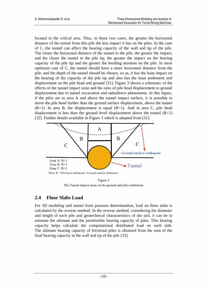
displacement on the pile head and ground [31]. Figure 3 shows a schematic of the
effects of the tunnel impact zone and the ratio of pile head displacement to ground
displacement due to tunnel excavation and subsidence phenomena. In this figure,
if the piles are in area A and above the tunnel impact surface, it is possible to
move the pile head further than the ground surface displacement, above the tunnel
(R>1). In area B, the displacement is equal (R=1). And in area C, pile head
displacement is less than the ground level displacement above the tunnel (R<1)
[32]. Further details available in Figure 3 which is adapted from [31].
Figure 3
The Tunnel impact areas on the ground and piles settlement
2.4 Floor Slabs Load
For 3D modeling and tunnel front pressure determination, load on floor slabs is
calculated by the reverse method. In the reverse method, considering the diameter
and length of each pile and geotechnical characteristics of the soil, it can be to
estimate the ultimate and the permissible bearing capacity of piles. This bearing
capacity helps calculate the computational distributed load on each slab.
The ultimate bearing capacity of frictional piles is obtained from the sum of the
final bearing capacity in the wall and tip of the pile [33].
Acta Polytechnica Hungarica Vol. 18, No. 4, 2021
– 219 –
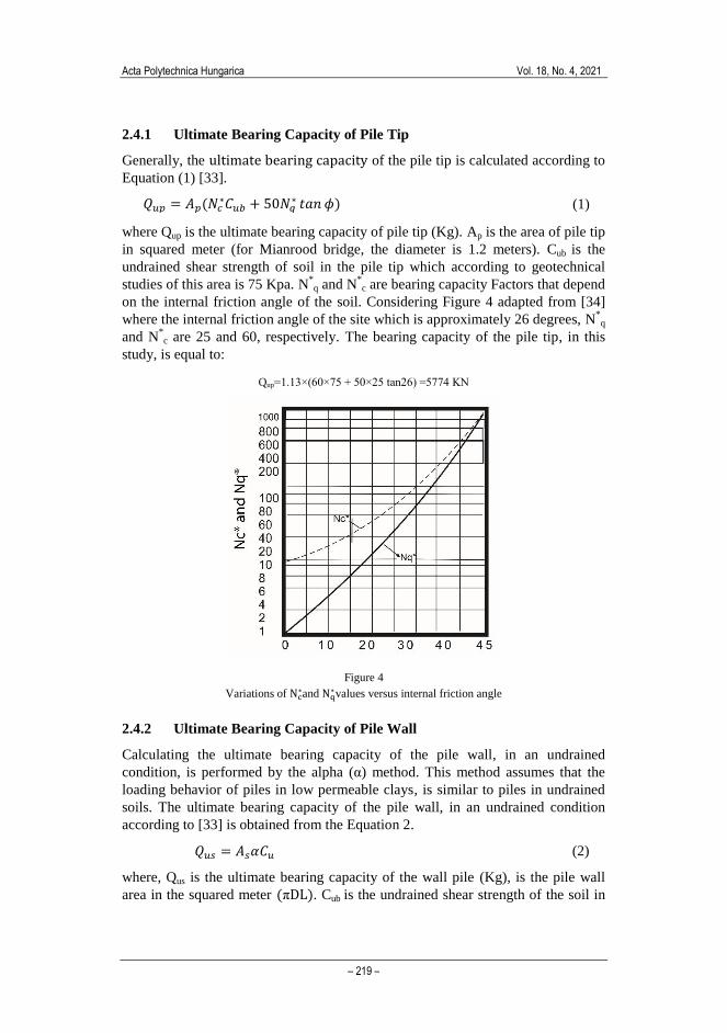
2.4.1 Ultimate Bearing Capacity of Pile Tip
Generally, the ultimate bearing capacity of the pile tip is calculated according to
Equation (1) [33].
𝑄𝑢𝑝 = 𝐴𝑝(𝑁𝑐∗𝐶𝑢𝑏 + 50𝑁𝑞
∗ 𝑡𝑎𝑛 𝜙) (1)
where Qup is the ultimate bearing capacity of pile tip (Kg). Ap is the area of pile tip
in squared meter (for Mianrood bridge, the diameter is 1.2 meters). Cub is the
undrained shear strength of soil in the pile tip which according to geotechnical
studies of this area is 75 Kpa. N*
q and N*c are bearing capacity Factors that depend
on the internal friction angle of the soil. Considering Figure 4 adapted from [34]
where the internal friction angle of the site which is approximately 26 degrees, N*
q
and N*c are 25 and 60, respectively. The bearing capacity of the pile tip, in this
study, is equal to:
Qup=1.13×(60×75 + 50×25 tan26) =5774 KN
Figure 4
Variations of Nc∗and Nq
∗values versus internal friction angle
2.4.2 Ultimate Bearing Capacity of Pile Wall
Calculating the ultimate bearing capacity of the pile wall, in an undrained
condition, is performed by the alpha (α) method. This method assumes that the
loading behavior of piles in low permeable clays, is similar to piles in undrained
soils. The ultimate bearing capacity of the pile wall, in an undrained condition
according to [33] is obtained from the Equation 2.
𝑄𝑢𝑠 = 𝐴𝑠𝛼𝐶𝑢 (2)
where, Qus is the ultimate bearing capacity of the wall pile (Kg), is the pile wall
area in the squared meter (πDL). Cub is the undrained shear strength of the soil in

D. Mohammadzadeh S. et al. Three-Dimensional Modeling and Analysis of Mechanized Excavation for Tunnel Boring Machines
– 220 –
the pile wall, which, according to geotechnical studies, is equal to 50 kPa. The α
value is an experimental factor that decreases the adhesion of the shaft wall soil.
This coefficient is less than one. Based on Figure 5, the value of this coefficient is
0.6 adapted from [34].
Figure 5
The graph of Cu (KN/m2) versus α
Due to the geometry of the bridge and the designed piles, the piles of the middle
slab are 25 meters long and the side slabs are 27 meters long.
𝑄𝑢𝑠(25𝑚) = 25 × 1.2 × 3.14 × 0.6 × 75 = 4239𝐾𝑁
𝑄𝑢𝑠(27𝑚) = 27 × 1.2 × 3.14 × 0.6 × 75 = 4578𝐾𝑁
By determining the ultimate bearing capacity of the pile, load allowed per pile can
be calculated as:
𝑄𝑤 =𝑄𝑢𝑝 + 𝑄𝑢𝑠
𝐹. 𝑆
(3)
where Qw is the permissible load on each pile (Kg). F.S is the safety factor for
each pile (4 in this study). From Eq. 3, the permissible bearing capacity of the pile
is:
𝑄𝑤 = (5774 + 4239)/4= 2503𝐾𝑁
The bearing capacity of piles in the middle slab
𝑄𝑤 = (5774 + 4578)/4= 2588𝐾𝑁
The bearing capacity of piles in the side slabs
Acta Polytechnica Hungarica Vol. 18, No. 4, 2021
– 221 –
The number of piles in the middle and side slabs is 8 and 10, respectively. Also,
the middle slab area is 111 m2, and the side slab area is 129 m
2. Considering the
bearing capacity of each pile and the number of piles, the load on each slab is
equal to:
q = (8*2503)/111= 180 KN/m2 Middle slab
q = (10*2588)/129= 200 KN/m2 Side slabs
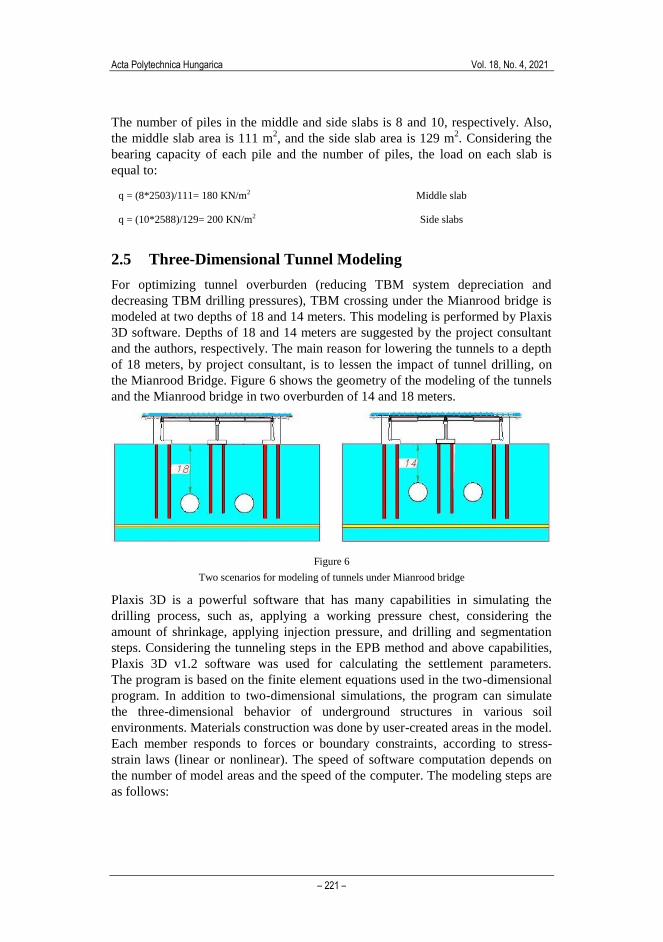
2.5 Three-Dimensional Tunnel Modeling
For optimizing tunnel overburden (reducing TBM system depreciation and
decreasing TBM drilling pressures), TBM crossing under the Mianrood bridge is
modeled at two depths of 18 and 14 meters. This modeling is performed by Plaxis
3D software. Depths of 18 and 14 meters are suggested by the project consultant
and the authors, respectively. The main reason for lowering the tunnels to a depth
of 18 meters, by project consultant, is to lessen the impact of tunnel drilling, on
the Mianrood Bridge. Figure 6 shows the geometry of the modeling of the tunnels
and the Mianrood bridge in two overburden of 14 and 18 meters.
Figure 6
Two scenarios for modeling of tunnels under Mianrood bridge
Plaxis 3D is a powerful software that has many capabilities in simulating the
drilling process, such as, applying a working pressure chest, considering the
amount of shrinkage, applying injection pressure, and drilling and segmentation
steps. Considering the tunneling steps in the EPB method and above capabilities,
Plaxis 3D v1.2 software was used for calculating the settlement parameters.
The program is based on the finite element equations used in the two-dimensional
program. In addition to two-dimensional simulations, the program can simulate
the three-dimensional behavior of underground structures in various soil
environments. Materials construction was done by user-created areas in the model.
Each member responds to forces or boundary constraints, according to stress-
strain laws (linear or nonlinear). The speed of software computation depends on
the number of model areas and the speed of the computer. The modeling steps are
as follows:
D. Mohammadzadeh S. et al. Three-Dimensional Modeling and Analysis of Mechanized Excavation for Tunnel Boring Machines
– 222 –
Geometry: Due to the overburden and the distance of the tunnels at the cross-
section, length of 60 meters and depth of 35 meters are considered for all models.
Dimensions are chosen so as unrealistic boundary conditions do not affect the
model. Two depths of 14 and 18 meters are provided for the tunnels.
Boundary Conditions: After defining two-dimensional and three-dimensional
geometry, it is the turn of the boundary conditions. Hinged and roller conditions
were considered for the bottom of the model and the sides, respectively.
According to section 2.4.2, the slab load in the middle and side slabs are 180
KN/m2 and 200 KN/m
2, respectively.
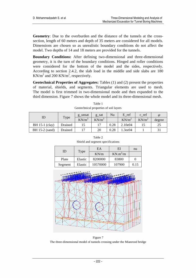
Geotechnical Properties of Aggregates: Tables (1) and (2) present the properties
of material, shields, and segments. Triangular elements are used to mesh.
The model is first trimmed in two-dimensional mode and then expanded to the
third dimension. Figure 7 shows the whole model and its three-dimensional mesh.
Table 1
Geotechnical properties of soil layers
𝜑 c_ref E_ref Nu g_sat g_unsat Type ID
degree KN/m2 KN/m2 KN/m3 KN/m3
25 15 2.10e04 0.28 17 15 Drained BH 15-1 (clay)
31 1 1.3ee04 0.28 20 17 Drained BH 15-2 (sand)
Table 2
Shield and segment specifications
nu EI EA Type ID
KN.m2/m KN/m
0 83800 8200000 Elastic Plate
0.15 107900 10570000 Elastic Segment
Figure 7
The three-dimensional model of tunnels crossing under the Mianrood bridge
Acta Polytechnica Hungarica Vol. 18, No. 4, 2021
– 223 –
Preliminary Conditions: After completing the previous steps, the initial
conditions (effective stresses) are based on the soil lateral pressure coefficient and
the water pressure. The water level is considered based on the geological maps in
the model.
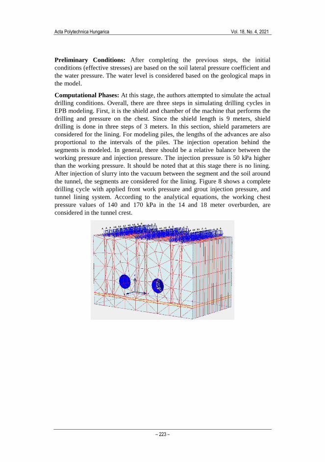
Computational Phases: At this stage, the authors attempted to simulate the actual
drilling conditions. Overall, there are three steps in simulating drilling cycles in
EPB modeling. First, it is the shield and chamber of the machine that performs the
drilling and pressure on the chest. Since the shield length is 9 meters, shield
drilling is done in three steps of 3 meters. In this section, shield parameters are
considered for the lining. For modeling piles, the lengths of the advances are also
proportional to the intervals of the piles. The injection operation behind the
segments is modeled. In general, there should be a relative balance between the
working pressure and injection pressure. The injection pressure is 50 kPa higher
than the working pressure. It should be noted that at this stage there is no lining.
After injection of slurry into the vacuum between the segment and the soil around
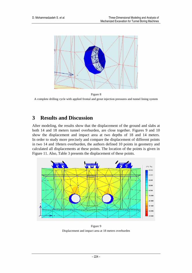
the tunnel, the segments are considered for the lining. Figure 8 shows a complete
drilling cycle with applied front work pressure and grout injection pressure, and
tunnel lining system. According to the analytical equations, the working chest
pressure values of 140 and 170 kPa in the 14 and 18 meter overburden, are
considered in the tunnel crest.
D. Mohammadzadeh S. et al. Three-Dimensional Modeling and Analysis of Mechanized Excavation for Tunnel Boring Machines
– 224 –
Figure 8
A complete drilling cycle with applied frontal and grout injection pressures and tunnel lining system
3 Results and Discussion
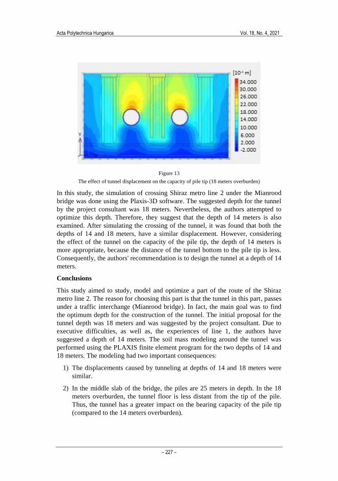
After modeling, the results show that the displacement of the ground and slabs at
both 14 and 18 meters tunnel overburden, are close together. Figures 9 and 10
show the displacement and impact area at two depths of 18 and 14 meters.
In order to study more precisely and compare the displacement of different points
in two 14 and 18eters overburden, the authors defined 10 points in geometry and
calculated all displacements at these points. The location of the points is given in
Figure 11. Also, Table 3 presents the displacement of these points.
Figure 9
Displacement and impact area at 18 meters overburden

Acta Polytechnica Hungarica Vol. 18, No. 4, 2021
– 225 –
Figure 10
Displacement and impact area at 14 meters overburden
Figure 11
The location of specified points by authors for comparing tunnel displacement

D. Mohammadzadeh S. et al. Three-Dimensional Modeling and Analysis of Mechanized Excavation for Tunnel Boring Machines
– 226 –
Table 3
The displacement of specified points in the model at two overheads of 14 and 18 meters
18 m Overburden 14 m Overburden Point
Dis. (mm) Dis. (mm)
17 17 A
22 20 B
15 14 C
13 13 D
16 15 E
12 11 F
12 11 G
12 11 H
15 15 I
14 13 J
Another important issue that should be considered is the distance from the bottom
of the tunnel to the tip of the pile. This distance affects the capacity of the pile tip.
Given that the depth of the piles in the middle slab of the bridge is 25 meters, if
the tunnel is located at a depth of 18 meters, the floor of the tunnel is
approximately 1.5 meters from the tip of the pile. When the tunnel is located at a
depth of 14 meters, the distance between the tunnel floor and the pile tip is greater.
Therefore, it is suggested that the designer changes the depth of the tunnel
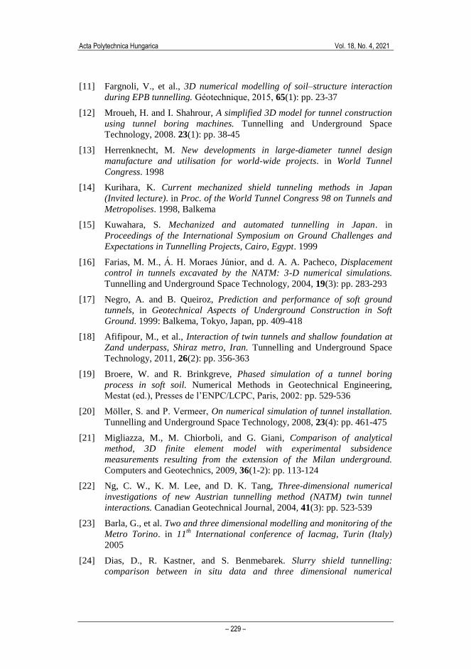
overburden from 18 meters to 14 or 15 meters. Figures 12 and 13 show the effect
of the location of the tunnel on the pile tip.
Figure 12
The effect of tunnel displacement on the capacity of pile tip (14 meters overburden)
Acta Polytechnica Hungarica Vol. 18, No. 4, 2021
– 227 –
Figure 13
The effect of tunnel displacement on the capacity of pile tip (18 meters overburden)
In this study, the simulation of crossing Shiraz metro line 2 under the Mianrood
bridge was done using the Plaxis-3D software. The suggested depth for the tunnel
by the project consultant was 18 meters. Nevertheless, the authors attempted to
optimize this depth. Therefore, they suggest that the depth of 14 meters is also
examined. After simulating the crossing of the tunnel, it was found that both the
depths of 14 and 18 meters, have a similar displacement. However, considering
the effect of the tunnel on the capacity of the pile tip, the depth of 14 meters is
more appropriate, because the distance of the tunnel bottom to the pile tip is less.
Consequently, the authors' recommendation is to design the tunnel at a depth of 14
meters.
Conclusions
This study aimed to study, model and optimize a part of the route of the Shiraz
metro line 2. The reason for choosing this part is that the tunnel in this part, passes
under a traffic interchange (Mianrood bridge). In fact, the main goal was to find
the optimum depth for the construction of the tunnel. The initial proposal for the
tunnel depth was 18 meters and was suggested by the project consultant. Due to
executive difficulties, as well as, the experiences of line 1, the authors have
suggested a depth of 14 meters. The soil mass modeling around the tunnel was
performed using the PLAXIS finite element program for the two depths of 14 and
18 meters. The modeling had two important consequences:
1) The displacements caused by tunneling at depths of 14 and 18 meters were
similar.
2) In the middle slab of the bridge, the piles are 25 meters in depth. In the 18
meters overburden, the tunnel floor is less distant from the tip of the pile.
Thus, the tunnel has a greater impact on the bearing capacity of the pile tip
(compared to the 14 meters overburden).

D. Mohammadzadeh S. et al. Three-Dimensional Modeling and Analysis of Mechanized Excavation for Tunnel Boring Machines
– 228 –
As a result, the authors propose to change the tunnel depth, from 18 to 14 meters.
For future studies, the authors intend to analyze other parts of the tunnels.
Furthermore, modeling can be done using different software such as Abaqus and
Flac, then comparing the results with Plaxis 3D.
Acknowledgment
The support of the Hungarian-Mexican bilateral project (2019-2.1.11-TÉT-2019-
00007) is acknowledged.
References
[1] Xu, W., P. Zhao, and L. Ning, Last train delay management in urban rail
transit network: Bi-objective MIP model and genetic algorithm. KSCE
Journal of Civil Engineering, 2018, 22(4): pp. 1436-1445
[2] Chen, H., B. Jia, and S. Lau, Sustainable urban form for Chinese compact
cities: Challenges of a rapid urbanized economy. Habitat international,
2008, 32(1): pp. 28-40
[3] Mohammadzadeh, D., et al. Urban train soil-structure interaction modeling
and analysis. in International Conference on Global Research and
Education. 2019, Springer
[4] Abdollahzadeh Nasiri, A. S., et al., Evaluation of Safety in Horizontal
Curves of Roads Using a Multi-Body Dynamic Simulation Process.
International Journal of Environmental Research and Public Health, 2020,
17(16): p. 5975
[5] Karballaeezadeh, N., et al., Estimation of flexible pavement structural
capacity using machine learning techniques. Frontiers of Structural and
Civil Engineering, 2020, 14(5): pp. 1083-1096
[6] Mayer, T. and C. Trevien, The impact of urban public transportation
evidence from the Paris region. Journal of Urban Economics, 2017, 102:
pp. 1-21
[7] Ding, R., et al., Heuristic urban transportation network design method, a
multilayer coevolution approach. Physica A: Statistical Mechanics and its
Applications, 2017, 479: pp. 71-83
[8] Li, L., et al., Urban transit coordination using an artificial transportation
system. IEEE Transactions on Intelligent Transportation Systems, 2010,
12(2): pp. 374-383
[9] Knox, P. L. and L. McCarthy, Urbanization: an introduction to urban
geography. 1994: Prentice-Hall Englewood Cliffs, NJ
[10] Tayyaran, M. R. and A. M. Khan, The effects of telecommuting and
intelligent transportation systems on urban development. Journal of Urban
Technology, 2003, 10(2): pp. 87-100
Acta Polytechnica Hungarica Vol. 18, No. 4, 2021
– 229 –
[11] Fargnoli, V., et al., 3D numerical modelling of soil–structure interaction
during EPB tunnelling. Géotechnique, 2015, 65(1): pp. 23-37
[12] Mroueh, H. and I. Shahrour, A simplified 3D model for tunnel construction
using tunnel boring machines. Tunnelling and Underground Space
Technology, 2008. 23(1): pp. 38-45
[13] Herrenknecht, M. New developments in large-diameter tunnel design
manufacture and utilisation for world-wide projects. in World Tunnel
Congress. 1998
[14] Kurihara, K. Current mechanized shield tunneling methods in Japan
(Invited lecture). in Proc. of the World Tunnel Congress 98 on Tunnels and
Metropolises. 1998, Balkema
[15] Kuwahara, S. Mechanized and automated tunnelling in Japan. in
Proceedings of the International Symposium on Ground Challenges and
Expectations in Tunnelling Projects, Cairo, Egypt. 1999
[16] Farias, M. M., Á. H. Moraes Júnior, and d. A. A. Pacheco, Displacement
control in tunnels excavated by the NATM: 3-D numerical simulations.
Tunnelling and Underground Space Technology, 2004, 19(3): pp. 283-293
[17] Negro, A. and B. Queiroz, Prediction and performance of soft ground
tunnels, in Geotechnical Aspects of Underground Construction in Soft
Ground. 1999: Balkema, Tokyo, Japan, pp. 409-418
[18] Afifipour, M., et al., Interaction of twin tunnels and shallow foundation at
Zand underpass, Shiraz metro, Iran. Tunnelling and Underground Space
Technology, 2011, 26(2): pp. 356-363
[19] Broere, W. and R. Brinkgreve, Phased simulation of a tunnel boring
process in soft soil. Numerical Methods in Geotechnical Engineering,
Mestat (ed.), Presses de l’ENPC/LCPC, Paris, 2002: pp. 529-536
[20] Möller, S. and P. Vermeer, On numerical simulation of tunnel installation.
Tunnelling and Underground Space Technology, 2008, 23(4): pp. 461-475
[21] Migliazza, M., M. Chiorboli, and G. Giani, Comparison of analytical
method, 3D finite element model with experimental subsidence
measurements resulting from the extension of the Milan underground.
Computers and Geotechnics, 2009, 36(1-2): pp. 113-124
[22] Ng, C. W., K. M. Lee, and D. K. Tang, Three-dimensional numerical
investigations of new Austrian tunnelling method (NATM) twin tunnel
interactions. Canadian Geotechnical Journal, 2004, 41(3): pp. 523-539
[23] Barla, G., et al. Two and three dimensional modelling and monitoring of the
Metro Torino. in 11th
International conference of Iacmag, Turin (Italy)
2005
[24] Dias, D., R. Kastner, and S. Benmebarek. Slurry shield tunnelling:
comparison between in situ data and three dimensional numerical
D. Mohammadzadeh S. et al. Three-Dimensional Modeling and Analysis of Mechanized Excavation for Tunnel Boring Machines
– 230 –
simulations. in Proceedings of The International Conference On Soil
Mechanics And Geotechnical Engineering. 2002, AA Balkema Publishers
[25] Dias, D., R. Kastner, and M. Maghazi. Three dimensional simulation of
slurry shield tunnelling. in Geotechnical aspects of underground
construction on soft ground. 2000
[26] Lambrughi, A., L.M. Rodríguez, and R. Castellanza, Development and
validation of a 3D numerical model for TBM–EPB mechanised
excavations. Computers and Geotechnics, 2012, 40: pp. 97-113
[27] Mollon, G., Etude déterministe et probabiliste du comportement des
tunnels. 2012, INSA de Lyon
[28] Mollon, G., D. Dias, and A.-H. Soubra, Probabilistic analyses of tunneling-
induced ground movements. Acta Geotechnica, 2013, 8(2): pp. 181-199
[29] Saadin, H. K. a. M., Analysis and Prediction of Land Surface Settlement
Due to Tunneling (Case Study: Tabriz Urban Train Line 2 Project).
Transportation Engineering, 2010, 4
[30] Ng, C. W., H. Huang, and G. Liu, Geotechnical Aspects of Underground
Construction in Soft Ground: Proceedings of the 6th
International
Symposium (IS-Shanghai 2008) 2008: CRC Press
[31] Jongpradist, P., et al., Development of tunneling influence zones for
adjacent pile foundations by numerical analyses. Tunnelling and
underground space technology, 2013, 34: pp. 96-109
[32] Selemetas, D., J. Standing, and R. Mair. The response of full-scale piles to
tunnelling. in Geotechnical aspects of underground construction in soft
ground. Proceedings of the 5th
international conference of TC 28 of the
ISSMGE, the Netherlands, 15-17 June 2005, 2006
[33] Schroeder, F. C., The influence of bored piles on existing tunnels. 2003
[34] Das, B. M., Principles of Foundation Engineering 6th Edition. 2007:
Thomson
Appendix
Term Description
TBM Tunnel Boring Machines
FEM Finite Element Method
EPB Earth Pressure Balance
Qup Ultimate Bearing Capacity of Pile Tip
Qus Ultimate Bearing Capacity of Pile Wall
F.S Safety factor
Kg Kilogram
KN Kilonewton