3D Image Reconstruction and Human Body Tracking using Stereo Vision and Kinect Technology
Three Dimensional High Dynamic Range Veillance for 3D ... · The dark and light exposures are ......
11
Three Dimensional High Dynamic Range Veillance for 3D Range-Sensing Cameras Raymond Lo, Valmiki Rampersad, Jason Huang, Steve Mann Department of Electrical & Computer Engineering, University of Toronto, Toronto, Ontario, Canada. http://www.eyetap.org Abstract—This paper presents the invention and implemen- tation of 3D (Three Dimensional) HDR (High Dynamic Range) sensing, along with examples. We propose a method of 3D HDR veillance (sensing, computer vision, video capture, or the like) by integrating tonal and spatial information obtained from multiple HDR exposures for use in conjunction with one or more 3D cameras. In one embodiment, we construct a 3D HDR camera from multiple 3D cameras such as Kinect sensors. In this embodiment the 3D cameras are arranged in a fixed array, such that the geometric relationships between them remain constant over time. Only a single camera calibration step is required at the initial time of assembling and fixing the cameras into the array. Preferably the cameras either view from the same position through beam splitters, or are fixed close to one another, so that they capture approximately the same subject matter. The system is designed so the cameras each capture a differently exposed image or video of approximately the same subject matter. In one embodiment, two Kinect cameras are attached together facing in the same direction, with an ND (Neutral Density) filter over one of them, so as to obtain a darker exposure. The dark and light exposures are combined to obtain more accurate 3D sensing in high contrast scenes. In another embodiment, a single 3D camera is exposure-sequenced (alternating light and dark exposures). 3D HDR might, more generally, be incorporated into existing 3D cameras, resulting in a new kind of 3D sensor that can work in nearly any environment, including high contrast scenes such as outdoor scenes, or scenes where a bright light is shining directly into the sensor. I. VEILLANCE ( WATCHING) IN HDR Three dimensional sensors create new possibilities for veil- lance. Our 3D HDR system, in particular, can be used for surveillance or sousveillance. There are two broad categories of veillance: • surveillance (stationary fixed cameras); and • sousveillance (wearable cameras). A. Surveillance The primary definition of the word “surveillance” is: 1) “a watch kept over a person, group, etc., especially over a suspect, prisoner, or the like: The suspects were under police surveillance.” [1] The etymology of this word is from the French word “surveiller” which means “to watch over”. Specifically, the word “surveillance” is formed from two parts: (1) the French prefix “sur” which means “over” or “from above”, and (2) the French verb “veiller” which means “to watch”. More generally, surveillance is the observation or recording of an activity by an inanimate object (machine), or by a person Fig. 1. Sousveillance denotes cameras worn by people. The “WearCamm” Wearable Camera system, also known as DEG (Digital Eye Glass), originally arose from the CYBORGlass welding helmet in the 1980s. Unlike other technologies of this era (e.g. 3M’s Speedglass which darkens globally), the CYBORGlass system is camera-based, and therefore allows the wearer’s vision to be modified computationally. Rays of light from the subject matter (here denoted as a “light bulb” image), denoted in blue, strike a 45-degree glass shade (denoted “GL45S”), arranged with a camera, such that rays of light that would otherwise enter the center of the iris of the eye enter the center of the iris of the camera. These diverted rays are also denoted in blue. The camera is connected to a display system or aremac that re-renders the modified view of visual reality onto the backside of the shade (rays denoted as red lines), thus allowing the wearer to see in HDR (Augmediated Reality). Dark areas of the image are augmented, whereas brigh areas are diminished. Addiitionally computer overlays are provided. The injection molded Digital Eye Glass pictured here was developed for everyday use, and was completed in 2002 (11 years ago). Notice how the wearer has the appearance of having a “glass eye”, hence the “glass eye effect”[10], hence the Eye Glass is sometimes called the “Glass Eye” or just “Glass”. not participating in the activity, i.e. by cameras borne by non- human objects. [2], [3], [4] B. Sousveillance: Putting cameras on people A more recently coined word is the word “sousveillance”, which is an etymologically correct opposite formed by re- placing the prefix “sur”, in “surveillance”, with its opposite, “sous” [2], [5], [6], [7]. Sousveillance generally refers to cameras borne by people, e.g. hand-held cameras or wearable cameras [2], [6], [7], [5], [8], [9]. “Sur” means “over” or “from above” (as in words like “surtax” or “surcharge”), wheras “Sous” means “under” or “from below” (as in “sous-chef”). 255 978-1-4799-0929-2/13/$31.00 c 2013 IEEE
Transcript of Three Dimensional High Dynamic Range Veillance for 3D ... · The dark and light exposures are ......

Three Dimensional High Dynamic Range Veillance
for 3D Range-Sensing Cameras
Raymond Lo, Valmiki Rampersad, Jason Huang, Steve Mann
Department of Electrical & Computer Engineering, University of Toronto, Toronto, Ontario, Canada.
http://www.eyetap.org
Abstract—This paper presents the invention and implemen-tation of 3D (Three Dimensional) HDR (High Dynamic Range)sensing, along with examples. We propose a method of 3D HDRveillance (sensing, computer vision, video capture, or the like) byintegrating tonal and spatial information obtained from multipleHDR exposures for use in conjunction with one or more 3Dcameras.
In one embodiment, we construct a 3D HDR camera frommultiple 3D cameras such as Kinect sensors. In this embodimentthe 3D cameras are arranged in a fixed array, such that thegeometric relationships between them remain constant over time.Only a single camera calibration step is required at the initialtime of assembling and fixing the cameras into the array.Preferably the cameras either view from the same positionthrough beam splitters, or are fixed close to one another, so thatthey capture approximately the same subject matter. The systemis designed so the cameras each capture a differently exposedimage or video of approximately the same subject matter. In oneembodiment, two Kinect cameras are attached together facing inthe same direction, with an ND (Neutral Density) filter over oneof them, so as to obtain a darker exposure. The dark and lightexposures are combined to obtain more accurate 3D sensing inhigh contrast scenes. In another embodiment, a single 3D camerais exposure-sequenced (alternating light and dark exposures).
3D HDR might, more generally, be incorporated into existing3D cameras, resulting in a new kind of 3D sensor that can workin nearly any environment, including high contrast scenes such asoutdoor scenes, or scenes where a bright light is shining directlyinto the sensor.
I. VEILLANCE (WATCHING) IN HDR
Three dimensional sensors create new possibilities for veil-
lance. Our 3D HDR system, in particular, can be used for
surveillance or sousveillance.
There are two broad categories of veillance:
• surveillance (stationary fixed cameras); and
• sousveillance (wearable cameras).
A. Surveillance
The primary definition of the word “surveillance” is:
1) “a watch kept over a person, group, etc., especially
over a suspect, prisoner, or the like: The suspects were
under police surveillance.” [1]
The etymology of this word is from the French word
“surveiller” which means “to watch over”. Specifically, the
word “surveillance” is formed from two parts: (1) the French
prefix “sur” which means “over” or “from above”, and (2) the
French verb “veiller” which means “to watch”.
More generally, surveillance is the observation or recording
of an activity by an inanimate object (machine), or by a person
Fig. 1. Sousveillance denotes cameras worn by people. The “WearCamm”Wearable Camera system, also known as DEG (Digital Eye Glass), originallyarose from the CYBORGlass welding helmet in the 1980s. Unlike othertechnologies of this era (e.g. 3M’s Speedglass which darkens globally), theCYBORGlass system is camera-based, and therefore allows the wearer’svision to be modified computationally. Rays of light from the subject matter(here denoted as a “light bulb” image), denoted in blue, strike a 45-degreeglass shade (denoted “GL45S”), arranged with a camera, such that rays of lightthat would otherwise enter the center of the iris of the eye enter the center ofthe iris of the camera. These diverted rays are also denoted in blue. The camerais connected to a display system or aremac that re-renders the modified viewof visual reality onto the backside of the shade (rays denoted as red lines),thus allowing the wearer to see in HDR (Augmediated Reality). Dark areas ofthe image are augmented, whereas brigh areas are diminished. Addiitionallycomputer overlays are provided. The injection molded Digital Eye Glasspictured here was developed for everyday use, and was completed in 2002 (11years ago). Notice how the wearer has the appearance of having a “glass eye”,hence the “glass eye effect”[10], hence the Eye Glass is sometimes called the“Glass Eye” or just “Glass”.
not participating in the activity, i.e. by cameras borne by non-
human objects. [2], [3], [4]
B. Sousveillance: Putting cameras on people
A more recently coined word is the word “sousveillance”,
which is an etymologically correct opposite formed by re-
placing the prefix “sur”, in “surveillance”, with its opposite,
“sous” [2], [5], [6], [7]. Sousveillance generally refers to
cameras borne by people, e.g. hand-held cameras or wearable
cameras [2], [6], [7], [5], [8], [9]. “Sur” means “over” or “from
above” (as in words like “surtax” or “surcharge”), wheras
“Sous” means “under” or “from below” (as in “sous-chef”).
255978-1-4799-0929-2/13/$31.00 c©2013 IEEE

Sousveillance arises from Digital Eye Glass (see Fig. 1)
which itself arises from the CYBORGlass (“MannGlas”) Dig-
ital Welding Glass (a welding shade mounted at a 45-degree
angle to divert eyeward bound rays of light into a camera
system, through a wearable computer, and then into a display
system).
C. High Dynamic Range (HDR) Imaging
HDR (High Dynamic Range) has been a well-known and
well-studied field of research for 20 years. Roberston et al.
write:
“The first report of digitally combining multiple
pictures of the same scene to improve dynamic range
appears to be Mann [11]. Algorithmic detail that
is lacking from Ref. [11] is provided in a later
publication, [12] where Mann and Picard explic-
itly examine the situation where multiple pictures,
each of different exposures, are taken of a scene.
They provide a method of merging these multiple
exposures to form a single image with an effective
dynamic range greater than that of the camera. By
making use of certainty functions, which give a
measure of the condence in an observation, Mann
and Picard weight the observations from the various
exposures to provide the final image. The certainty
function for a particular camera is computed as the
derivative of the camera response function, which re-
sults in low condence for pixel values near extremes,
and higher confidence for pixel values between these
extremes.” [13]
HDR photography [14], [15], [16], [17], [18] and video [19],
[20], [21], [22], [23] are attractive topics as they address one
of the most fundamental problem of digital camera sensors,
namely their limited dynamic range.
Moreover, HDR is not limited to being only applicable to
color cameras, or the visible spectrum. It can also be applied
to cameras that operate outside the visible spectrum, such
as infrared cameras, as well as to 3D cameras. The light
capturing mechanism of cameras, whether it be analog (film)
or digital (CMOS/CCD sensors), can only record a limited
range of light from any scene. Combining differently exposed
images of the same scene can produce an image of higher
range than any of the individual images used to create it. The
invention of the infrared (IR) 3D camera proposed in this
paper brings forth the added spatial dimension and extends
the spectral range that can be captured. Using both a visual
light camera and an IR-3D camera allows the capture of
an additional spatial dimension and extended spectral range.
Applying HDR photography techniques to such a combined
system not only increases the dynamic range of the visual
camera but possibily also the range of the additional spatial
dimension (e.g. making 3D cameras useful outdoors in bright
sunlight or in high contrast scenes where glare from bare light
bulbs might otherwise degrade the 3D data).
D. Conventional uses of Kinect: Surveillance
The Kinect system, from Microsoft, was designed for use
with Microsoft’s XBox 360 gaming console. The Kinect
system allows the gamer to interact with games without the
need for physical controls. It accomplishes this by tracking the
user’s movements and position in 3-Dimensional space, with
respect to itself, in real-time. In normal use, the Kinect sits
stationary and observes the gamer as he/she moves. In this
sense, the Kinect was envisioned and created as a surveillance
camera (i.e. to be borne by inanimate objects rather than to
be worn).
E. Reversing the role of user and camera: Sousveillance
We propose the use of the Kinect like 3D sensing cameras
in a different manner, where the Kinect moves with the user,
so that it observes the real world in a similar fashion as the
user observes (or would have observed, in the case of a blind
individual). Rather than having the Kinect watch the user,
the user uses it to watch their environment. In one of our
wearable implementation as shown in Fig. 2, the Kinect is
used to extract the 3-dimensional depth information of the
environment being observed by the user.
There are numerous potential applications for such a system:
• Seeing and sensing aid [24]
• EyeTap wearable Digital Eye Glass [20], [19], [21]
• 3D (sur/sou)veillance
• 3D scanning and reconstruction [25]
• Surface tracking and gesture input for wearable comput-
ers
F. The fundamental problem of sousveillance: Dynamic Range
With surveillance, we can carefully place the camera in the
optimum location. In using the Kinect to observe a typical
living room, for example, the user will often give careful
consideration to its placement, being sure to avoid placing
it where sunlight might shine in from windows and the like.
The user may move lamps out of its field of view, in order to
reduce glare that prevents it from working properly.
However, with sousveillance, we don’t have such luxury.
When using the Kinect as a seeing aid, for self-gesturing
(gesture-sensing wearable applications), and marker or mark-
erless surface tracking, it would be unreasonable to demand
the environment to conform to our needs.
Generally surveillance is the monitoring of one’s own
property like one’s own living room, i.e. a space that one has
control over. On the other hand, sousveillance involves seeing
in property that might not belong to the wearer. For example,
the gesture-sensing camera or seeing aid must function in any
environment where we cannot demand the owner of the space
to remove lamps that are causing glare, or the like.
Thus this problem of dynamic range must be solved in
the sousveillance device itself and not require changing the
environment.
256 2013 IEEE International Symposium on Technology and Society (ISTAS)

(a) Top (b) Front (c) Side
Fig. 2. Wearable Digital Eye Glass Prototype. Our custom 3D printed design allows users to wear the digital glass in everyday life. The proposed algorithmcan be utilized for improving the dynamic range of the camera and thus allowing the users to see ‘better’ in daily life. Notice that our proposed systemnot only allows users to see in high contract scene, it also enables night vision due to the use of active depth sensor which projects IR light patterns andreconstruct 3D information about the scene. These provides users the ability to see in extreme environments, and also allows for robust tracking algorithm tobe integrated with the eyeglasses.
G. Technology Behind Microsoft’s Kinect
Microsoft’s Kinect employs PrimeSense’s 3-D sensing tech-
nology. PrimeSense’s 3-D sensor uses light coding to compute
the scene volume, using active IR (infrared) illumination [26],
[27], [28]. The sensor then uses a CMOS image sensor to read
the light coding infrared patterns back from the scene. The
coded light is processed by PrimeSense’s SoC [29], contained
in the 3-D sensor, to give the depth information.
II. BACKGROUND AND THEORY
In this section, we describe the geometric representation of
the cameras and the formation of images with a pinhole camera
model. These provide the fundamentals for reconstructing
images with the depth information from multiple Kinects. For
consistency, the notation used in this paper closely follows
the works in [30], [31]. Then, we extend the discussion into
the High Dynamic Range (HDR) image composition with 3D
data points. Here we describe our novel algorithm that merges
the differently exposed sets from the 3D data from multiple
Kinects.
A. Pinhole Camera Model and Perspective Projection
To understand the geometric relationship between the cam-
era and the scene, we first assume that the camera follows
a pinhole camera model. That is, a scene view is formed by
projecting a 3D point into the image plane using a perspective
transformation.
Let’s denote a 2D point on an image plane as m =[u, v, 1]T , and a 3D point in the scene as M = [X,Y, Z, 1]T ,
in homogeneous coordinates.
With a pinhole camera model, the relationship between 3D
points M and its image projection m is given by
sm = A[R t]M, (1)
where [R t] called the extrinsic parameters describe the
translation and rotation relationship between the real-world
coordinates system and the camera coordinates system.
�
����
�
�����
Fig. 3. This figure illustrates one of our proposed configuration. Each Kinectcamera C1 and C2 provides a 3D measure of the scene. With the 3D data, wecan reconstruct the scene and re-position C1 and C2 onto a virtual cameraV in any arbitrary position. This configuration allows us to perform HDRcomposition as if the images were simultaneously captured from the samecamera. The distance between the cameras d can be estimated using a cameracalibration method.
On the other hand, the matrix A in (1) is called the intrinsic
parameters of the camera, and is given by
A =
⎡⎣α β u0
0 γ v00 0 1
⎤⎦ . (2)
In (2), the (u0, v0) is the principle point, and α, β, and
γ describes the scaling, and the skew of the image in uand v axes. In general, the camera may have a single focal
length lens, and these intrinsic parameters only require to be
estimated once per setup.
B. Lens Distortion Correction
Real lenses suffer various level of distortions. For simplicity,
we address the lens distortion problem by considering the ra-
dial and tangential distortion correction which can be modelled
2013 IEEE International Symposium on Technology and Society (ISTAS) 257

Fig. 4. Our proposed configuration with two Kinect cameras. The upperKinect camera is augmented with a polarized neutral density filter for manualadjustment of the exposure.
by a simplified Brown’s model [32]
r =√(x2 + y2),
x′ = x(1 + k1r2 + k2r
4) + p1(r2 + 2x2) + 2p2xy,
y′ = y(1 + k1r2 + k2r
4) + p2(r2 + 2y2) + 2p1xy
(3)
where (x′, y′) are the ideal pixel image coordinates after the
distortion correction, (x, y) are real observed image coordi-
nates centered at the principle point, and k1, k2, p1, p2 are the
coefficients of the radial and tangential distortion respectively.
These parameters can be estimated using a camera calibration
method by providing a known geometry to the scene. One
example would be to use a checkerboard pattern on a planar
surface, and this technique will be discussed in the next
section.
C. Camera Calibration
In order to combine the tonal and spatial information for
our proposed setup, it is necessary to calibrate the cameras;
i.e., estimate the extrinsic and intrinsic parameters described
previously, and also estimate the camera response function for
correcting the non-linearity in the HDR composition process.
Camera calibration is a well-studied problem in the computer
vision field and numerous techniques had been proposed [31],
[18], [13] for correcting and estimating these parameters. Their
implementations can be found in the common computer vision
libraries such as OpenCV1.
1) Geometric Calibration: For our configuration, we have
the Kinect cameras position on top of the other as shown in
Fig. 3. It is possible to have these cameras further apart or
closer together. However, the advantage of placing the camera
closer together is that the cameras share a common field of
view, which reduces the ‘holes’ due to occlusion. Since the
relative position of the cameras is fixed, in our setup, the
calibration process is only required to be computed once -
increases the flexibility and portability of our approach.
1OpenCV http://opencv.org
Equations (1) and (2) provided a model for the camera
relations. Given an image set of some known planar pattern
(such as checkerboard), we can recover the intrinsic and
extrinsic parameters of the cameras in (1) using the methods
in [31]. Additionally, the lens distortion parameters described
in (3) are also modelled and thus estimated from the process.
Once these parameters are estimated, the 3D data from each
camera can be mapped to the real-world coordinates, allowing
us to combine the data in the next step.
In addition, we estimate the relative pose, [Ri ti], for each
ith Kinect in in the real-world coordinates to allow for a
global registration of the 3D data. By setting one of the
Kinect camera as a reference (origin), we can then describe the
relative position of the Kinect cameras using simple matrices.
All parameters extracted from our setup are summarized in
Table I.2) Photometric Calibration: Another key challenge in cal-
ibrating the Kinect is its lack of exposure controls. Instead
of programming the camera for different exposure settings,
in our configuration, a polarized variable neutral density filter
was attached to one of the Kinect to reduce the exposure as
shown in Fig. 4. To capture differently exposed images on a
Kinect, we programmed the Kinect for manual exposure, and
thus the Kinect does not compensate for any changes to the
lighting condition and alter the exposures unexpectedly. Then,
we manually adjust the filter to extract a set of images that
varies in some known exposures for the recovery of the camera
response function[18].
TABLE IPARAMETERS ESTIMATED FROM THE CAMERA CALIBRATION PROCESS
Parameter(s) Type Description
Aci, Ari Intrinsic Focal length, principle points, andskews for the color camera and theinfrared camera of the ith Kinect
kc1i, kc2i, pc1i,pc2i
Intrinsic Lens distortion coefficients for thecolor camera of the ith Kinect
kr1i, kr2i, pr1i,pr2i
Intrinsic Lens distortion coefficients for theinfrared camera of the ith Kinect
Ri, ti Extrinsic Geometric relations between theinfrared camera and the color cam-era of the ith Kinect
Rij , tij Extrinsic Geometric relations between theith and the jth Kinect in the scene
fr(q), fg(q),fb(q)
Photometric The camera response function foreach color channel
3) Summary: Table I summarized the parameters required
for the 3D HDR reconstruction step. For our experiment, we
have used two Kinect cameras and the first Kinect is set as
the reference camera. For example, the matrices R21 and t21defines the transformation of how 3D data is transformed from
the second Kinect camera to the first Kinect camera. Lastly,
the photometric calibration provided us a camera response
function that describe the non-linear relationship in both the
IR and the color camera.
D. 3D Point Cloud Reconstruction from Kinects
Each of the Kinect camera provides a 3D measure of the
scene with the color camera and the infrared-based depth
258 2013 IEEE International Symposium on Technology and Society (ISTAS)
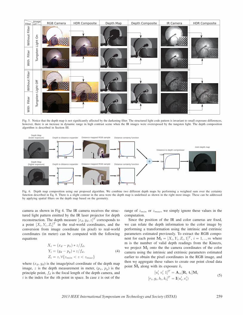
Fig. 5. Notice that the depth map is not significantly affected by the darkening filter. The structured light code pattern is invariant to small exposure differences,however, there is an increase in dynamic range in high contrast scene when the IR images were overexposed by the tungsten light. The depth compositionalgorithm is described in Section III.
����������� ��������
����������� ��������
������ ���������� �
������ ���������� �
�����������������������
�������������������������������
�������������
�������������������
����� ������
��������� ������������
Fig. 6. Depth map composition using our proposed algorithm. We combine two different depth maps by performing a weighted sum over the certaintyfunction described in Eq. 8. There is a slight contour in the area were the depth map is undefined as shown in the right most image. These can be addressedby applying spatial filters on the depth map based on the geometry.
camera as shown in Fig 4. The IR camera receives the struc-
tured light pattern emitted by the IR laser projector for depth
reconstruction. The depth measure [xd, yd, z]T corresponds to
a point [Xi, Yi, Zi]T in the real-world coordinates, and the
conversion from image coordinate (in pixel) to real-world
coordinates (in meter) can be computed with the following
equations
Xi = (xd − px) ∗ z/fd,
Yi = (yd − py) ∗ z/fd,
Zi = z, ∀{zmin < z < zmax}
(4)
where (xd, yd) is the image/pixel coordinate of the depth map
image, z is the depth measurement in meter, (px, py) is the
principle point, fd is the focal length of the depth camera, and
i is the index for the ith point in space. In case z is out of the
range of zmin or zmax, we simply ignore these values in the
computation.
Since the position of the IR and color cameras are fixed,
we can relate the depth information to the color image by
performing a transformation using the intrinsic and extrinsic
parameters estimated previously. To extract the RGB compo-
nent for each point Mi = [Xi, Yi, Zi, 1]T , i = 1, ..,m where
m is the number of valid depth readings from the Kinects,
we project Mi onto the the camera coordinates of the color
camera using the intrinsic and extrinsic parameters estimated
earlier to obtain the pixel coordinates in the RGB image, and
then we aggregate these values to create our point cloud data
point Mi along with its exposure ki
[u′
i v′
i 1]T = Aci[Ri ti]Mi
[ri, gi, bi, ki]T = I(u′
i, v′
i)(5)
2013 IEEE International Symposium on Technology and Society (ISTAS) 259

where Ri and ti defines the rotation and translation of the
camera position from the IR camera to the color camera
coordinates. Since the projection may result in a non-integer
pixel coordinate for (u′
i, v′
i), we would estimate its value by
performing a linear interpolation on the neighboring pixels
in the color image I. From each Kinect, we construct a set
of point cloud data Mi = [Xi, Yi, Zi, ri, gi, bi, ki]T which
consists of a 7-dimensional vector of the spatial and tonal
information about the scene.
III. HIGH DYNAMIC RANGE DEPTH MAP
The Kinect camera contains the source of the projected
IR pattern as well as the IR image sensor. Based on the
observation of the distortion in the pattern of the scene, the
device is able to compute the distance of the objects in the
view. The observation, however, is affected by the material
property and the distance of the objects. The objects are
usually overexposed in close proximity to the camera and
the pattern reflected off the objects at far are too dark and
underexposed. This becomes a problem for the camera to
determine the distance of the objects that are not well exposed.
Due to the limited dynamic range per exposure setting, the
perceived patterns by the infrared camera are lost in the over-
or under-exposed areas of the scene.
The dynamic range problem can be resolved by capturing
multiple exposures of the scene using the infrared camera. At
the lower exposure, the details of closer objects is more visible
to the IR sensor, while at the higher exposure, the details of far
objects become more visible. For depth maps recovered from
differently exposed IR images, the unknown depths, due to
the lost details from one exposure, could be compensated by
another. The collection of depth maps forms a high dynamic
range depth map, which allows a greater coverage of depth
calculation under a more diverse lighting condition.
A. Comparagram Of Depth Map
A comparagram is a cross histogram of two images of
different exposures [33]. A comparagram reveals the compara-
metric relationship of the outputs of the same camera with
different exposure settings. In our purpose of extending the
depth map range based on the Wyckoff set of depth maps, we
attempt to directly observe the relationship between the depth
maps produced by the infrared images from different exposure
settings. The resulting comparagram in Fig. 8 shows that the
known depth values from the images of the Wyckoff set are
the same. Therefore, the response f(∗) of the depth value dis simply f(d) = d.
B. Compositing Of Depth Map
The resulting comparagram in Fig. 7 and Fig. 5 showed that
the depth values are invariant to slight changes to exposures on
the infrared sensor. In case of a scene with IR light source, a
darkening filter can improve the depth map reconstruction be-
cause it reduces the exposures (see Fig 5) in the over-saturated
area. To combine the depth maps for the HDR reconstruction
with a single Kinect, we adapt to the composition method
described by [33] and apply certainty (or weight) on the
estimated distance value of different depth maps. In contrast
to [33], the certainty function for the distance value is not
based on the camera response of the infrared sensor. Instead
we design the certainty function based on the sensitivity of
the depth map to distance conversion. Denote g(r) as the
distance response function that converts the known distance
r of the objects in meters to depth values and g−1(d) as its
inverse response, we obtain the certainty function by taking
the derivative of g(r) with respect to distance. According to
[24], we could convert the disparity map to depth map using
the following equation
r = g−1(d) = 1/(α · d+ β) (6)
where α=−0.0030711016 and β=3.3309495161 are the pa-
rameters extracted from the least squared regression. Its cer-
tainty function
c(r) =δg(r)
δr=
{−1
α·r2, if rmin ≤ r ≤ rmax
0, otherwise(7)
where rmin≈0.3m and rmax≈5.3m are calibrated based on
our Kinect cameras. Lastly, the joint estimate of distance from
two sensors with different exposure settings is expressed as the
weighted sum per pixel
rjoint =
∑c(ri) · ri∑c(ri)
(8)
where ri denotes the estimated distance value observed by the
ith sensor.
IV. 3D HIGH DYNAMIC RANGE COMPOSITION WITH
KINECT(S)
High Dynamic Range imaging has been discussed exten-
sively in the literature. By combining differently exposed
images of the same subject matter, we can further extend the
dynamic range of the sensors. In Fig. 5, we see that it is
possible to capture a higher dynamic range with the Kinect by
taking multiple exposures of the same subject matter with a
Kinect that is augmented with a polarized variable ND filter. In
this section, we will discuss our novel technique for combining
the data for producing an HDR 3D point cloud that has higher
dynamic range in both tonal and spatial range that cannot be
possibly captured by a single exposure. For simplicity, we will
first discuss the approach with a single Kinect for capturing a
static scene. The images are captured by adjusting the exposure
on the variable ND filter and we assume that the camera and
the scene are both static. Then, we propose an approach for
constructing 3D HDR from data captured simultaneously from
multiple Kinect cameras. One key contribution of this paper
is the novel approach and the unique configuration that allows
simultaneous capturing, reconstruction, and rendering of 3D
HDR data stream from 3D range sensing cameras.
260 2013 IEEE International Symposium on Technology and Society (ISTAS)

��� ������� ��� ����������� ���������������
Fig. 7. Image pairs used for comparagram construction. Three different Wyckoff sets of two depth maps were captured to cover the full range of depth values.The exposure difference between the bright and the dark infrared image is 1 EV apart. The resulting depth map comparagram per Wyckoff set is shown inthe right most column of the figure. Each covers a partial range of depth values in its comparagram.
������� ������ ����� �������
Fig. 8. Comparagram of depth maps taken at various exposure differences. The comparagrams exhibit the same linear mapping of depth value obtained frominfrared image pairs that are 1/3, 2/3, 1 or 4/3 stop apart.
2013 IEEE International Symposium on Technology and Society (ISTAS) 261

Fig. 9. Camera calibration and 3D projection of the point cloud data inworld coordinate. Notice that with our setup one camera is upside downand the camera calibration is affected by the orientation and perspectivedifference. The corners from the checkerboard are used for the estimationof the [Rij tij ] in the camera calibration step. The images in the second roware the projection of the point cloud data from two separate Kinect camerasC1 and C2 onto the virtual camera V , and rendered with OpenGL. Noticethat with our configuration the Kinects can capture differently exposed imagesat the same time, and th
A. Backgrounds
In our configuration, we capture a set of images, possibly
synchronously among the Kinects, to produce two point cloud
data sets that capture differently exposed images of the scene
along with their 3D data: Mi and Nj, i = 1, ..,m, j = 1, .., n,
where m and n are the number of point clouds data recon-
structed from Kinects.
We denote f and f−1 as the ‘camera response’ and the ‘in-
verse camera response’ respectively. A pixel, p, is the camera
response of quantigraphic measure, q, at a selected exposure
level, k, which can be expressed as p = f(kq). Inversely, the
estimate of q from a single exposure is q = f−1(p)k−1
i . Thus
the joint estimate qjoint = fjoint(k1q1, .., kiqi, .., knqn) can
be computed using the methods proposed by [18], [13], [34]
based on a Wyckoff set [17] of size N , for N ≥ 1.
B. HDR Composition with a Single Kinect
Similar to the approach proposed in [20], we can easily
combine the differently exposed images using the weighted
sum approach. The HDR image undergoes a real-time
tonemapping algorithm [20] to allow for displaying on low
dynamic range (LDR) displays. Additionally, the depth map
composition will create a depth map that has fewer missing
depth points than any of the single depth maps. Using Equation
(4) and (5), we can then create a 3D point cloud data as our
desired HDR output.
C. Simultaneous HDR Composition with Multiple Kinects
In contrast to the typical HDR composition algorithm where
the composition is performed on two images from the same
image plane, we propose an algorithm that operates on the
3D data from the Kinect that are captured from two different
perspective simultaneously. That is, instead of only concern-
ing about the tonal information, we have additional spatial
parameters that would be considered in the HDR composition
process. One key advantage of this approach is that we can
capture simultaneously which reduces the registration problem
due to camera, or in frame motions. Furthermore, this allows
us to capture 3D HDR real-time (30 FPS) video of the scene.
However, there are several trade offs in this approach and these
limitations are discussed in Section VI.
D. 3D Image Registration
The Kinect camera provides us a 3D measure of the scene.
We can register the point cloud data Mi and Nj from the
differently exposed RGB images by projecting the cameras
Ci to Cj and vice-versa based on their geometric relations
estimated in the camera calibration process.
In Equation 5, we described the image registration for
obtaining the RGB image from the depth map on a Kinect.
Similarly, we can extend such a mapping by first transforming
the jth Kinect to the ith Kinect’s coordinates and then obtain
the RGB value from the ith Kinect’s color camera
[u′
i v′
i 1]T = Aci[Ri ti][Rji tji]Nj
[ri, gi, bi, ki]T = I(u′
i, v′
i).(9)
Now, for each Mi and Ni we have found a corresponding
pair [ri, gi, bi, ki] and [rj , gj , bj , kj ] for the HDR composition
step. Following the steps described in Section IV-B, we can
compose an HDR image as if the color images were captured
from the same camera as shown in Fig. 9.
E. 3D Point Cloud Merging
The approach discussed in Section 9 suggested that we
could perform 3D composition of the RGB data by re-
projecting the cameras onto the same image plane. Instead,
we can operate directly on the point cloud data and merge the
data directly in 3D space.
Given two point cloud data sets Mi and Nj where i, j are
the index for the ith and the jth point in space, we compute
their new correspondence set by finding the candidate with the
best score in the similarities metrics
I(i, j) = (wijdij + cijlij)/(wij + cij),
dij = ||Xi −Xj ||,
lij = ||kiQ(ri, gi, bi)− kjQ(rj , gj , bj)||
(10)
where X = [X,Y, Z] is the position in the real-
world coordinates, Q(r, g, b) is the light quantity vector
[f−1(r), f−1(g), f−1(b)]T based on the camera response
function, ki and kj are the exposure values, and wij and cij are
weight functions on the spatial and tonal data. The weighted
functions can be defined as a penalty on the uncertainties in
the point cloud data
cij = sc
wij = sd/(e(Zi) + e(Zj))(11)
262 2013 IEEE International Symposium on Technology and Society (ISTAS)

Fig. 10. Compositing of the point cloud data Mi and Nj in 3D space.The point cloud data from each Kinect are projected onto the real-worldcoordinates and merged based on the tonal and spatial information in (10).dij is the distance between two point cloud data in meter and r is the searchradius.
where c and e are the certainty function of the depth map and
the color image, and sd and sc is a scaling variable for the
weight.
To reduce the complexity of the matching process, a k-d tree
data structure is used for the search for potential candidates in
close proximity. For data points that have no matches, perhaps
due to shadows, or ‘holes’ in the depth map, we simply add
those data to the final result by remapping the [r, g, b] into
light vectors [qr, qg, qb].
V. RESULTS
We successfully created an array of Kinect cameras, to
capture differently exposed 3D data. In one example, using
two Kinect cameras, where one is fitted with a neutral density
filter, we obtained two simultaneously captured yet differently-
exposed 3D sensing videos of the same subject matter. We
have tested the resulting 3D HDR camera on scenes with light
shining directly into the camera. In particular, in the worst-
case scenario, namely a tungsten light bulb that emits light
in both visible spectrum and infrared spectrum, which was
placed directly in the scene with no lamp shade, our 3D HDR
camera produced excellent results, even though the individual
3D cameras failed.
A. Wearable HDR 3D Digital Eye Glass
Our results suggested that by applying high dynamic range
imaging technique to both spatial and tonal domain, we
can achieve more robust tracking system and seeing aid in
everyday use. To verify the feasibility of the system, we
created an unique wearable 3D HDR eyeglasses prototype for
everyday use. In Fig. 2, a functional prototype which utilizes
the PrimeSense 3D range sensing camera (the same technology
that is used in Kinect camera) and the EPSON Moverio head
mounted display is shown. The prototype allows us to further
explore the use of HDR imaging with 3D camera sensors in
different scenarios. For example, the wearable setup allows
users to see an aug-mediated reality system which rendered
the high dynamic range 3D information from the POE (point
of eye) of the wearer as shown in Fig. 11).
VI. DISCUSSION
This paper proposed a method to reconstruct 3D HDR scene
using one or more Kinect. However, there are several trade offs
we shall consider in our proposed configuration. Particularly,
there are some key limitations shall be addressed in the future
work in order to produce high quality 3D HDR videos for
everyday use.
1) Interference among Kinects: The Kinect uses a struc-
tured light pattern to reconstruct 3D data from the scene with
the help from an IR laser projector. When multiple Kinects
are used in the same space, there are interferences that would
reduce the accuracy of the depth measure. Several approaches
had been proposed to reduce such problem (e.g., [35]). One
solution is to combine different 3D sensing technology such
as time-of-flight 3D sensor (e.g., SoftKinetic) to reduce the
interference between the sensors.
2) Programmable 3D cameras: Unfortunately, the current
Kinect does not provide fine grain control over the exposure
settings and thus an ND filter is required for our setup. In
addition, Kinect sensor does not provide hardware support in
synchronizing the data streams, and thus we still suffer a minor
latency issue.
3) High Resolution and High Accuracy Depth Sensor:
One leading limiting factor for the reconstruction stage is the
spatial resolution and noise performance of the 3D sensors.
In the future, a higher resolution depth map will significantly
improve the overall accuracy and the quality of the output.
4) Noise Modeling and Filtering: Lastly, to improve the
results we can employ various noise reduction algorithms for
both of the image and depth map image. Particularly, the depth
map often shows missing data (e.g., holes and shadows) in the
scene, see Fig. 11. These can be addressed by applying spatial
and temporal filters [36] on the depth map stream to improve
our final results.
VII. SOCIAL IMPLICATIONS
One of the applications of our 3D HDR system is wearable
computing. An HDR camera system, in general, enables the
user to capture a wider variety of scenes than a regular camera
which can only capture LDR scenes. That is, an HDR camera
system can see into dark and bright area of scenes ‘better’ than
conventional cameras. Therefore, a wearable 3D HDR EyeTap
wearable computing device can act as a vision aid - enhancing
and protecting the viewers vision. For example, through an
HDR camera system, a user can look into the headlights of
a car in a dark alley and still see the license plate and the
driver’s face. A user can also safely view welding which would
otherwise be harmful to the naked eye [19].
2013 IEEE International Symposium on Technology and Society (ISTAS) 263

(a) Lower Exposure (b) Higher Exposure (c) HDR Result
(d) 3D Reconstruction (e) Our proposed HDR result rendered in 3D
Fig. 11. Example of our 3D HDR rendering for wearable eyeglasses. Notice that the low exposure image captures the detail of the book cover but unableto capture the background. On the other hand, the high exposure image captures the background image but the highlight detail of surfaces such as the bookcover and the mouse on the desk are saturated. By combining the images and the depth maps, we reconstruct a 3D reconstruction of the scene from a virtualcamera. By projecting the scene onto wearer’s POE, we can reconstruct a scene from the same prespective as how the users may see in real life.
The 3D HDR system used in this fashion, as a vision
aid in a wearable computing platform, can be classified as
a sousveillance system [3], [37], [2], that is, instead of a
camera system mounted on a building, which is surveillance,
the camera is human-centric and the world through this device
is captured as a first person view. In the past several decades
and in present times, there have been a number of debates
in the mass media over the appropriate use of sousveillance
devices, such as wearable camera systems (e.g. CYBORGlass,
MannGlas, and more recently, Google Glass). On one hand,
sousveillance devices are viewed as a deprivation of personal
privacy that should be forbidden in any public area. On the
other hand, others view such devices as a revolutionary per-
sonal assistance that can act as a visual aid and perform aug-
mented and (aug)mediated reality [39] tasks, such as providing
an interactive augmented/augmediated reality interactions on
subject matter in view of a user as the user sees it in a first-
person view [40].
As a vision aid, it is impractical for it to be forbidden, as
those forbidding it will assume liability for any side effects of
non-usage (e.g. if a person trips and falls because they were
required to not wear their DEG). Moreover, in a Surveillance
Society, sousveillance may provide a necessary balance-of-
power between the authorities and individuals.
VIII. CONCLUSION
We successfully demonstrated a 3D HDR camera con-
structed from two Kinect sensors, one of which was fitted
with a neutral density filter. The resulting differently exposed
(one darker and one lighter) data streams were merged in 3D
to compensate for the parallax induced by the cameras being
in slightly different positions.
We were able to capture 3D information from high contrast
scenes. This suggests the possibility of making 3D cameras
that can work in outdoor settings or settings where lights are
shining directly into the camera. Thus it is possible to build a
3D camera that can be used for sousveillance (e.g. wearable
gesture-sensing), where the wearer does not necessarily have
control over the placement of lighting fixtures and the like in
the scene.
REFERENCES
[1] “Online etymology dictionary, douglas harper,” 2010. [Online].Available: http://dictionary.reference.com/browse/surveillance
[2] S. Mann, J. Nolan, and B. Wellman, “Sousveillance: Inventing andusing wearable computing devices for data collection in surveillanceenvironments.” Surveillance & Society, vol. 1, no. 3, pp. 331–355, 2002.
264 2013 IEEE International Symposium on Technology and Society (ISTAS)

[3] S. Mann, “Sousveillance: inverse surveillance in multimedia imaging,”in Proceedings of the 12th annual ACM international conference on
Multimedia. ACM, 2004, pp. 620–627.[4] K. Dennis, “Viewpoint: Keeping a close watch–the rise of self-
surveillance and the threat of digital exposure,” The Sociological Review,vol. 56, no. 3, pp. 347–357, 2008.
[5] G. Fletcher, M. Griffiths, and M. Kutar, “A day in thedigital life: a preliminary sousveillance study,” SSRN,
http://papers.ssrn.com/sol3/papers.cfm?abstract id=1923629,September 7, 2011.
[6] K. Michael and M. Michael, “Sousveillance and point of view technolo-gies in law enforcement: An overview,” 2012.
[7] J. Bradwell and K. Michael, “Security workshop brings’ sousveil-lance’under the microscope,” 2012.
[8] C. Reynolds, “Negative sousveillance,” First International Conference ofthe International Association for Computing and Philosophy (IACAP11),pp. 306 – 309, July 4 - 6, 2011, Aarhus, Denmark.
[9] V. Bakir, Sousveillance, media and strategic political communication:
Iraq, USA, UK. Continuum, 2010.[10] S. Mann, “Mediated reality with implementations for everyday life,”
Presence Connect, August 6 2002, wearcam.org/presenceconnect.[11] ——, “Compositing multiple pictures of the same scene,” in Proceedings
of the 46th Annual IS&T Conference. Cambridge, Massachusetts: TheSociety of Imaging Science and Technology, May 9-14 1993, pp. 50–52,iSBN: 0-89208-171-6.
[12] S. Mann and R. Picard, “Being ‘undigital’ with digital cameras: Ex-tending dynamic range by combining differently exposed pictures,”M.I.T. Media Lab Perceptual Computing Section, Cambridge, Mas-sachusetts, Tech. Rep. 323, 1994, also appears, IS&T’s 48th an-nual conference, pages 422-428, May 7–11, 1995, Washington, D.C.,http://wearcam.org/ist95.htm.
[13] M. Robertson, S. Borman, and R. Stevenson, “Estimation-theoreticapproach to dynamic range enhancement using multiple exposures,”Journal of Electronic Imaging, vol. 12, p. 219, 2003.
[14] F. M. Candocia, “A least squares approach for the jointdomain and range registration of images,” IEEE ICASSP,vol. IV, pp. 3237–3240, May 13-17 2002, avail. athttp://iul.eng.fiu.edu/candocia/Publications/Publications.htm.
[15] ——, “Synthesizing a panoramic scene with a common exposure via thesimultaneous registration of images,” FCRAR, May 23-24 2002, avail.at http://iul.eng.fiu.edu/candocia/Publications/Publications.htm.
[16] A. Barros and F. M. Candocia, “Image registration inrange using a constrained piecewise linear model,” IEEE
ICASSP, vol. IV, pp. 3345–3348, May 13-17 2002, avail. athttp://iul.eng.fiu.edu/candocia/Publications/Publications.htm.
[17] C. Wyckoff, “An experimental extended response film,” SPIE Newslett,pp. 16–20, 1962.
[18] S. Mann, “Compositing multiple pictures of the same scene,” in Pro-
ceedings of the 46th Annual IS&T Conference, vol. 2, 1993.[19] S. Mann, R. Lo, J. Huang, V. Rampersad, and R. Janzen, “Hdrchitecture:
real-time stereoscopic hdr imaging for extreme dynamic range,” in ACM
SIGGRAPH 2012 Emerging Technologies. ACM, 2012, p. 11.[20] R. C. H. Lo, S. Mann, J. Huang, V. Rampersad, and T. Ai, “High
dynamic range (hdr) video image processing for digital glass,” inProceedings of the 20th ACM international conference on Multimedia.ACM, 2012, pp. 1477–1480.
[21] S. Mann, R. Lo, K. Ovtcharov, S. Gu, D. Dai, C. Ngan, and T. Ai, “Re-altime hdr (high dynamic range) video for eyetap wearable computers,fpga-based seeing aids, and electric eyeglasses,” image, vol. 1, no. 2,pp. 3–4, 2012.
[22] M. D. Tocci, C. Kiser, N. Tocci, and P. Sen, “A Versatile HDRVideo Production System,” ACM Transactions on Graphics (TOG)
(Proceedings of SIGGRAPH 2011), vol. 30, no. 4, 2011.[23] S. Kang, M. Uyttendaele, S. Winder, and R. Szeliski, “High dynamic
range video,” ACM Transactions on Graphics, vol. 22, no. 3, pp. 319–325, 2003.
[24] S. Mann, J. Huang, R. Janzen, R. Lo, V. Rampersad, A. Chen, andT. Doha, “Blind navigation with a wearable range camera and vibrotac-tile helmet,” in Proceedings of the 19th ACM international conference
on Multimedia. ACM, 2011, pp. 1325–1328.[25] S. Izadi, D. Kim, O. Hilliges, D. Molyneaux, R. Newcombe, P. Kohli,
J. Shotton, S. Hodges, D. Freeman, A. Davison et al., “Kinectfusion:real-time 3d reconstruction and interaction using a moving depth cam-era,” in Proceedings of the 24th annual ACM symposium on User
interface software and technology. ACM, 2011, pp. 559–568.[26] A. Shpunt, “DEPTH MAPPING USING MULTI-BEAM ILLUMINA-
TION,” Jan. 21 2008, uS Patent App. 12/522,172.[27] A. Shpunt and B. Pesach, “OPTICAL PATTERN PROJECTION,”
Jul. 21 2010, uS Patent App. 12/840,312.[28] A. Shpunt and Z. Zalevsky, “Depth-varying light fields for three dimen-
sional sensing,” Mar. 13 2007, uS Patent App. 11/724,068.[29] E. Spektor, Z. Mor, and D. Rais, “INTEGRATED PROCESSOR FOR
3D MAPPING,” Mar. 4 2009, uS Patent App. 12/397,362.[30] G.-Q. Wei and S. De Ma, “Implicit and explicit camera calibration:
Theory and experiments,” Pattern Analysis and Machine Intelligence,
IEEE Transactions on, vol. 16, no. 5, pp. 469–480, 1994.[31] Z. Zhang, “A flexible new technique for camera calibration,” Pattern
Analysis and Machine Intelligence, IEEE Transactions on, vol. 22,no. 11, pp. 1330–1334, 2000.
[32] D. C. Brown, “Decentering distortion of lenses,” Photometric Engineer-ing, vol. 32, no. 3, pp. 444–462, 1966.
[33] S. Mann and R. Picard, “Beingundigital’with digital cameras,” 1994.[34] M. A. Ali and S. Mann, “Comparametric image compositing: Computa-
tionally efficient high dynamic range imaging,” in To appear, Proc. Int.
Conf. Acoust., Speech, and Signal Processing (ICASSP). IEEE, March2012.
[35] A. Maimone and H. Fuchs, “Reducing interference between multiplestructured light depth sensors using motion,” in Virtual Reality Work-
shops (VR), 2012 IEEE. IEEE, 2012, pp. 51–54.[36] S. Matyunin, D. Vatolin, Y. Berdnikov, and M. Smirnov, “Temporal
filtering for depth maps generated by kinect depth camera,” in 3DTV
Conference: The True Vision-Capture, Transmission and Display of 3D
Video (3DTV-CON), 2011. IEEE, 2011, pp. 1–4.[37] S. Mann, J. Fung, and R. Lo, “Cyborglogging with camera phones:
Steps toward equiveillance,” in Proceedings of the 14th annual ACM
international conference on Multimedia. ACM, 2006, pp. 177–180.[38] P. Mistry and P. Maes, “Sixthsense: a wearable gestural interface,” in
ACM SIGGRAPH ASIA 2009 Sketches. ACM, 2009, p. 11.[39] R. Hill, J. Fung, and S. Mann, “Reality window manager: A user inter-
face for mediated reality,” in Proceedings of the 2004 IEEE International
Conference on Image Processing (ICIP2004), 2004, pp. 24–27.[40] C. Aimone, J. Fung, and S. Mann, “An eyetap video-based featureless
projective motion estimation assisted by gyroscopic tracking for wear-able computer mediated reality,” Personal and Ubiquitous Computing,vol. 7, no. 5, pp. 236–248, 2003.
2013 IEEE International Symposium on Technology and Society (ISTAS) 265