Three-Dimensional Entanglement: Knots, Knits and Nets
36
Three-Dimensional Entanglement: Knots, Knits and Nets Myfanwy Ella Evans January 2011 A thesis submitted for the degree of Doctor of Philosophy of The Australian National University Department of Applied Mathematics Australian National University
Transcript of Three-Dimensional Entanglement: Knots, Knits and Nets

Three-Dimensional Entanglement:Knots, Knits and Nets
Myfanwy Ella Evans
January 2011
A thesis submitted for the degree of Doctor of Philosophy
of The Australian National University
Department of Applied MathematicsAustralian National University

Chapter 5
Dilatancy of Woven Filament Arrays
We have developed a technique to generate a variety of close-packed arrays of one dimen-
sional filaments, via projection of free tilings in the two-dimensional Hyperbolic plane
(H2) into three-dimensional Euclidean space (E3), as decribed in Ch. 3. A rich catalogue
of filament are constructed using this technique, with varying degrees of entanglement of
the filaments. In Ch. 4, we have adapted algorithms developed to form canonical ‘ideal’
or ‘tight’ embeddings of knots [Katr 96, Pier 98] to arrive at canonical geometries for our
weavings.
The existence of curvilinear filament geometries in tight weavings has an unexpected
consequence, namely the possibility of 3D weavings that exhibit dilatancy, accompanied
by a lowering of the fibre packing fraction and the formation of a more open weave: the
volume of the weaving may be expanded while maintaining the inter-filament contacts
through filament straightening. Equivalently, an internally driven straightening of the fil-
aments within the tight configuration of a dilatant weaving will result in an expansion of
the material without loss of filament contacts. We see dilatancy as an attractive material
property and dilatant weaving as design target for new materials.
The free volume within a chiral, cubic and finitely dilatant weaving, the ideal con-
formation of the G129C structure, a helical version of the Σ+ rod packing, expands more
than 5-fold on filament straightening. This remarkable three-dimensional weaving allows
variation of packing density without loss of structural rigidity and is an attractive design
target for materials. We propose that the ideal G129C weaving is formed by keratin fibres
in the outermost layer of mammalian skin, likely templated by a folded membrane.
181

182 Dilatancy of Woven Filament Arrays
5.1 Dilatant filament weavings
To determine if a 3-periodic weaving is dilatant, end-state configurations of the weaving
under dilation must be prescribed. The initial configuration is the ideal form as determined
by the PB-SONO algorithm described in Ch. 4; this has maximum filament diameter and
a maximum number of inter-filament contacts per filament length (standardised by the fil-
ament diameter). We call the terminal configuration the maximal configuration, realised as
follows. The unit cell is repeatedly subjected to homothetic expansion while maintaining
the filament diameter, and the filaments subsequently tightened within the swollen unit
cell. (This is equivalent to shrinking the filament diameter while maintaining the unit cell
size and subsequently tightening the filaments.) The maximal configuration is reached
when a further unit cell expansion results in a loss of contacts between filaments.
Closer analysis of 3D weavings reveals a rich taxonomy, amongst which we find three
distinct classes. The simplest examples exhibit zero dilatancy. In these cases the ideal con-
figuration and the maximal configuration of the weaving coincide. A second class contains
weavings which dilate to accommodate a finite change in unit cell volume. When fully di-
lated, these finitely dilatant weavings retain all inter-fibre contacts and remain jammed. In
their least dense state, finitely dilatant weavings contain rectilinear fibres and their fibre
packing fraction decreases continuously during dilation, yet remains positive. The third
class comprises infinitely dilatant weavings, characterised by a decrease of fibre packing
fraction to zero. Since this fully dilated state is only realised for fibres of positive diam-
eter by swelling the unit cell without limit, finite volumes of infinitely dilatant weavings
will never realise this limit, since only infinitely long fibres remain jammed. We note
that the hypothetical infinitely dilated configuration may consist of straight or curvilinear
fibres. (In practice, infinitely dilatant weavings expand until they unjam due to loss of
mutual contacts, and this end-state depends on the original fibre length.) Some examples
demonstrate these various weaving classes1.
Numerical tightening of the D124C structure, equivalent to the Π∗ rod packing, revealed
that the ideal structure is composed of straight rods (Fig. 5.1(a)). Inflation of the unit cell
while maintaining the filament diameter induces a reduction in the number of inter-fibre
contacts per unit cell (Fig. 5.1(b)). Hence the tight and maximal configurations of this rod
packing are equivalent, and we can infer that the weaving is not dilatant.
1A further class of finitely dilatant weavings can be imagined for which the maximal configuration containscurvilinear fibres. To date, however, we have failed to find an example of this class.

§5.1 Dilatant filament weavings 183
(a) (b)
Figure 5.1: The D124C structure, equivalent to the Π∗ rod packing, has zero dilatancy. (a) The idealform of the structure within one unit cell. (b) An expansion of the unit cell immediately results inthe loss of contacts between filaments.
Indeed, any weaving whose ideal configuration contains rectilinear filaments is not
dilatant. However, weavings whose ideal forms display curvilinear filaments need not be
dilatant. Fig. 5.2 shows the ideal D114C(3) structure, which is a tangled version of the #2
rod packing [OKee 05]. This structure is not dilatant, yet the ideal structure is composed of
interwoven helical components. Fig. 5.2 also shows that inflation of the unit cell induces
a loss of many inter-filament contacts.
(a) (b)
Figure 5.2: The ideal D114C(3) structure, which is a tangled version of the #2 rod packing, is notdilatant. (a) The ideal unit cell, which contains curvilinear fibres. (b) A unit cell inflation inducesthe loss of some inter-filament contacts i.e. the red and blue filaments in the top right corner of thecell are not longer in contact.
Among the 3D weavings generated in Ch. 3, we have found a number of dilatant
examples. Recall from the previous chapter, § 4.3.3, the ideal G124C structure (helical Π+
rod packing) is composed of helical filaments (Fig. 5.3(a)). Successive unit cell expansions

184 Dilatancy of Woven Filament Arrays
induce straightening of the helical filaments without loss of inter-filament contacts. This
expansion can be continued until a final state where the filaments are completely straight
and the unit cell is finite, forming the Π+ rod packing. This is the maximal configuration
(Fig. 5.3(b)). The helical filaments of the ideal Π+ packing have length 6.466 within a
(1×1×1) unit cell, and a radius of 0.181: hence the packing fraction is 0.665. On dilation,
the packing fraction decreases to 0.295 in the maximal configuration: the packing fraction
is more than halved on cooperative straightening.
(a) (b)
Figure 5.3: The ideal G124C structure (helical Π+ rod packing) is finitely dilatant. (a) The idealunit cell. (b) Consecutive unit cell expansions occur without the loss of inter-filament contacts, andthe maximal configuration is the Π+ rod packing.
A particularly large and finite dilatant behaviour is associated with the ideal form of
the G129C structure, which is a chiral, cubic arrangement equivalent to a helical Σ+ rod
packing. The ideal structure, shown in Fig. 5.4(a), contains helicoidal filaments that lie
almost completely within one channel of the Gyroid surface, as seen in Ch. 4. The maximal
configuration of the structure contains straight rods, and is precisely the Σ+ rod packing
(Fig. 5.4(b)). The helical filaments of the ideal structure have length 7.642 within a (1×
1×1) unit cell, and a radius of 0.127, and hence a packing fraction of 0.387. The packing
fraction of the weaving decreases to 0.075 in the maximal configuration: a 5-fold decrease
in the packing fraction. This weaving thus offers a fascinating target structure for rigid
weavings capable of extreme variations in filament packing densities.
We also observe finitely dilatant behaviour in anisotropic weavings, such as the trig-
onal structure H31C(1), constructed in Ch. 3. The ideal structure has undulating filaments
in a rhombohedral unit cell, as shown in Fig. 5.5(a). The maximal configuration is a trig-
onal rod packing of straight components, as shown in Fig. 5.5(b). In the ideal unit cell,

§5.1 Dilatant filament weavings 185
(a) (b)
Figure 5.4: The ideal G129C structure, related to the Σ+ rod packing, is finitely dilatant. (a) Thetight unit cell. (b) The maximal state, which has no loss of inter-filament contacts, and is exactlythe Σ+ rod packing.
L = 4.444 and R = 0.181, which gives a packing fraction of 0.525 (for lattice parameters
(a = b = c = 1; α = β = π2 ; γ = π
3 )). The packing fraction of the weaving decreases to
0.204 in the maximal configuration: more than half of the ideal packing fraction.
(a) (b)
Figure 5.5: The anisotropic trigonal structure H31C(1) is finitely dilatant. (a) The tight unit cell. (b)A unit cell inflation may be performed without the loss of inter-filament contacts, and the maximalconfiguration is composed of straight rods.
Infinitely dilatant weavings necessarily differ from those weavings that are related to
crystallographic rod packings, since in the latter case the (straight) fibres are intersection-
free, inducing a maximal configuration with a finite unit cell. However, weavings whose
filaments intersect on straightening, as constructed in the previous chapter, § 4.3.3, are
infinitely dilatant. In these cases, all inter-filament contacts remain, regardless of the in-
crease in unit cell volume. For example, the weaving G+118C(1), which has intersecting

186 Dilatancy of Woven Filament Arrays
filaments on straightening and whose ideal configuration is shown in Fig. 5.6(a), is in-
finitely dilatant. The images in Fig. 5.6(b,c) demonstrate that regardless of the amplitude
of a unit cell expansion, all inter-filament contacts remain.
(a) (b) (c)
Figure 5.6: The ideal G+118C(1) weaving is infinitely dilatant. (a) The ideal unit cell. (b) A small
expansion sees all inter-filament contacts remain. (c) A further expansion also sees all contactspreserved. An infinite expansion see all contacts remain and the packing fraction approach zero.
Infinite dilatancy is also seen for the D118C(1) structure, whose ideal and expanded
configurations are shown in Fig. 5.7, where all possible unit cell expansions see all inter-
filament contacts preserved. It seems, within the limited catalogue of examples constructed
in this thesis, that all weavings whose filaments intersect on straightening to their average
axes are infinitely dilatant.
(a) (b) (c)
Figure 5.7: The D118C(1) structure is infinitely dilatant. (a) The ideal form within one unit cell.(b) A unit cell expansion sees the filaments remain in contact. (c) A further unit cell expansion alsohas all contacts preserved.

§5.1 Dilatant filament weavings 187
A second genre of infinitely dilatant weaving contains filaments which are sufficiently
tangled to preclude rectification of the filaments without changing ambient isotopy type.
For example, consider the G+118C(2) structure, which is a tangled version of a packing
which contains a triple helix each rod trajectory of the Γ. The unit cell size can be expanded
without limit, without the loss of any inter-filament contacts, as illustrated in Fig. 5.8, thus
this weaving is infinitely dilatant.
(a) (b) (c)
Figure 5.8: The ideal G+118C(2) structure is infinitely dilatant. (a) The ideal unit cell. (b) A unit
cell expansion sees the filaments remain in contact. (c) A further unit cell expansion also has allcontacts preserved.
As a further example, consider the ideal G−118C(2) structure, which is a woven variant
of the Σ+ rod packing. We see from the consecutive unit cell expansions in Fig. 5.9 that all
contacts are preserved through the expansions, and the packing is also infinitely dilatant.
(a) (b) (c)
Figure 5.9: The ideal G−118C(2) structure, which is a woven Σ+ rod packing, is infinitely dilatant.
(a) The ideal unit cell. (b) A unit cell expansion sees the filaments remain in contact. (c) A furtherunit cell expansion also has all contacts preserved.

188 Dilatancy of Woven Filament Arrays
A formal definition of the rectification transformation for dilatant weavings runs as
follows. We construct a one-parameter family of embeddings of weavings parametrised
by the variable γ, which describes the fractional dilation. The initial tightest weaving
is associated with γ = 0; the end-state of the dilation process, realised for the maximal
configuration is realised when γ = 1. The magnitude of the dilatancy realised during the
expansion process for a variety of weavings is listed in Table 5.1.
Table 5.1: Structural measurements for various structure, all normalised for unit cells of unitvolume and fibres of radius R. All weavings are cubic, except H31C(1), which has hexagonal latticeparameters (a = b = c = 1; α = β = π
2 ; γ = π3 ). L is the total fibre length per unit cell; γ defines the
ideal and maximal states. f (γ) denotes the filament volume fraction. The dilatancy induced by fibrerectification is quantified by the fractional change in free and total volumes: ∆ f ree (= Vf ree(γmax)
Vf ree(0) )
and ∆tot (= Vtot (γmax)Vtot (0) ), where Vf ree and Vtot denote the free volume and the total unit cell volume
respectively.
Structure straight? class cubic? γ R(γ) L(γ) f (γ) ∆ f ree ∆tot
G+123C(2) (Γ)
√non-dilatant cubic 0 0.177 6.933 0.682 1 1
H31C(1) X (ideal) dilatant (I) trig. 0 0.181 4.444 0.525√(dilated) 1 0.115 4.243 0.204 4.330 2.581
G124C X (ideal) ” cubic 0 0.181 6.466 0.662(Π+)
√(dilated) 1 0.125 6 0.295 4.688 2.247
G129C X (ideal) ” cubic 0 0.127 7.642 0.384(Σ+)
√(dilated) 1 0.058 6.927 0.073 7.899 5.429
G+118C(1) X (ideal) dilatant (II) cubic 0 0.073 18.082 0.303√
(dilated) 1 0 16.965 0 ∞ ∞
D118C(1) X (ideal) ” cubic 0 0.065 19.614 0.260√(dilated) 1 0 16.971 0 ∞ ∞
G−118C(2) X (ideal) dilatant (III) cubic 0 0.075 10.714 0.189X (dilated) < 1 0.03 8.006 0.022 ∞ ∞
G+118C(2) X (ideal) ” cubic 0 0.066 29.074 0.398
X (dilated) < 1 0.02 24.284 0.031 ∞ ∞
We allow only jammed configurations of the weavings during the dilation transfor-
mation, for which the number of inter-fibre contacts per unit cell is conserved. Note,

§5.1 Dilatant filament weavings 189
however, that if the fibre length per unit cell is reduced during dilation, the density of
inter-fibre contacts per unit cell for outermost fragments of the weaving is reduced, due to
this contraction. This variation leads to softening of the weaving rigidity, due to a dearth
or excess of unsupported fibres in the corona. This effect is difficult to quantify, due to
some flexibility in the fibre arrangement in the (unjammed) corona. A simple gauge is the
number of contacts per unit length of the fibre, measured throughout the dilation process.
Data are normalised against the G124C weaving, that has the largest number of inter-fibre
contacts per unit length of known weavings, whose number of fibre-fibre contacts is scaled
to unity.
Figure 5.10: Plot of number of inter-filament contacts per unit length (for unit diameter bres) asa function of porosity for a non-dilatant weaving (G123(2)) and some finite and infinitely dilatantexamples. The shaded region indicates the range of porosities found in human corneocytes fromleast to most hydrated.
Dilation data for some of the 3D weavings in Table 5.1 are plotted in Fig. 5.10,
which allows comparison of the rate of dilation, along with the range of porosities sus-
tained by various weavings. These data reveal the very distinct character of various weav-
ings. Infinitely dilatant weavings exhibit extraordinary dilation properties, however, this
is achieved at the expense of significant reduction in the density of inter-fibre contacts.
These cases are therefore expected to significantly soften on dilation, and finite volumes
of these weavings are likely to unjam on swelling. It is also worth noting that these ex-

190 Dilatancy of Woven Filament Arrays
amples are less dense (for given porosity) than the finitely dilatant weavings, occupying a
significantly larger total volume (for the same total fibre content).
Figure 5.11: Dependence of total weaving volume per unit cell on porosity (where all bres arenormalised to unit diameter) for a non-dilatant weaving (G123(2)) and some finite and infinitelydilatant examples. The shaded region indicates the range of porosities found in human corneocytesfrom least to most hydrated.
Among the finitely dilatant weavings, we find significant variation in the material prop-
erties as a function of dilation. Two distinct regimes emerge, depending on the porosity
of the dilated weavings. If the porosity is less than about 60%, the G124C and H31C(1)
weavings are the most compact, with the highest density of inter-fibre contacts. Above
this porosity value (to ca. 93%, when the weaving is maximally dilated), dilated versions
of the G129C weaving affords the most compact weaving, with the highest density of inter-
fibre contacts.
§5.2 Keratin alignment in corneocytes 191
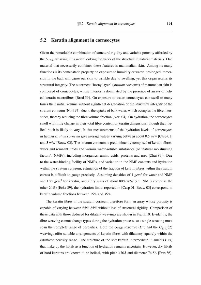
5.2 Keratin alignment in corneocytes
Given the remarkable combination of structural rigidity and variable porosity afforded by
the G129C weaving, it is worth looking for traces of the structure in natural materials. One
material that necessarily combines these features is mammalian skin. Among its many
functions is its homeostatic property on exposure to humidity or water: prolonged immer-
sion in the bath will cause our skin to wrinkle due to swelling, yet this organ retains its
structural integrity. The outermost “horny layer” (stratum corneum) of mammalian skin is
composed of corneocytes, whose interior is dominated by the presence of arrays of heli-
cal keratin macrofibres [Brod 59]. On exposure to water, corneocytes can swell to many
times their initial volume without significant degradation of the structural integrity of the
stratum corneum [Norl 97], due to the uptake of bulk water, which occupies the fibre inter-
stices, thereby reducing the fibre volume fraction [Norl 04]. On hydration, the corneocytes
swell with little change in their total fibre content or keratin dimensions, though their he-
lical pitch is likely to vary. In situ measurements of the hydration levels of corneocytes
in human stratum corneum give average values varying between about 0.5 w/w [Casp 01]
and 3 w/w [Bouw 03]. The stratum corneum is predominantly composed of keratin fibres,
water and remnant lipids and various water-soluble substances (or ‘natural moisturising
factors’, NMFs), including inorganics, amino acids, proteins and urea [Zhai 89]. Due
to the water-binding facility of NMFs, and variation in the NMF contents and hydration
within the stratum corneum, estimation of the fraction of keratin fibres within the stratum
cornea is difficult to gauge precisely. Assuming densities of 1 gcm3 for water and NMF
and 1.25 gcm3 for keratin, and a dry mass of about 80% w/w (i.e. NMFs comprise the
other 20%) [Ecke 89], the hydration limits reported in [Casp 01, Bouw 03] correspond to
keratin volume fractions between 15% and 35%.
The keratin fibres in the stratum corneum therefore form an array whose porosity is
capable of varying between 65%-85% without loss of structural rigidity. Comparison of
these data with those deduced for dilatant weavings are shown in Fig. 5.10. Evidently, the
fibre weaving cannot change types during the hydration process, so a single weaving must
span the complete range of porosities. Both the G129C structure (Σ+) and the G+118C(2)
weavings offer suitable arrangements of keratin fibres with dilatancy squarely within the
estimated porosity range. The structure of the soft keratin Intermediate Filaments (IFs)
that make up the fibrils as a function of hydration remains uncertain. However, dry fibrils
of hard keratins are known to be helical, with pitch 470A and diameter 74.5A [Fras 86],

192 Dilatancy of Woven Filament Arrays
Figure 5.12: Porosity of the material increases as the filaments straighten cooperatively: A spheri-cal section of the G129C material in the tight configuration increases in porosity on straightening ofthe filaments. The result is the standard configuration of the Σ+ rod packing.
giving a ratio of pitch to diameter of 6.3. Further, the structure of dry soft keratin IFs,
comprising the stratum corneum, is likely to be similar [Fras 86].
The ideal G+118C(2) weaving contains fibres whose geometry are complex modulated
helices, with a simple axis, contrary to the structure of IFs. In contrast, the ideal G129C
(Σ+) weaving is made of helical filaments (which are slightly triangular when projected
along their axis, rather than the circular sections of ideal helices). Further, in their tightest
configuration, corresponding to the dry state, the ratio of their pitch to fibre diameter is
6.8, close to that proposed by [Fras 86]. (Scaling the (tightest) G129C weaving to give the
measured pitch of 470A implies a lattice parameter of about 550A for the weaving.) The
remarkable dilatancy of the G129C weaving, which spans the measured porosity variations
between dry and hydrated corneocytes, coupled with the agreement in helical dimensions
in keratin IFs and the filament shape in the ideal chiral cubic weaving, suggest that keratin
fibrils indeed weave within corneocytes according to the G129C pattern. We suggest that
the one-parameter family of 3D weavings related to the G129C rod packing best describes
the ideal arrangement of keratin fibres within individual corneocytes. Indeed, the G129C
rod packing affords a low density, rigid 3D weaving, whose economy makes it an ideal
geometry for a biomaterial.
A qualitative picture of the hydration process according to this model runs as follows.
Exposure to water induces the keratin fibres to unwind by sliding over each other, without
compromising their structural rigidity imposed by their inter-fibre contacts. The number
of point contacts per unit cell remains fixed, but they move along the fibres, thereby gen-
erating additional free volume accessible to the water. Cooperative unwinding occurs, re-

§5.2 Keratin alignment in corneocytes 193
Figure 5.13: The ideal configuration of the G129C structure lies to within a good approximationwithin a single labyrinth of the gyroid.
sulting in isotropic expansion of the corneocytes. We predict that swelling of corneocytes
beyond the free volume accessible to the straightened rod packing will lead to dramatic
weakening, since further swelling of the pattern can only occur by losing contacts be-
tween fibres, thereby diminishing the structural integrity of the corneocytes. Indeed, there
is a limit to water uptake in skin, beyond which the stratum corneum loses its protective
barrier [Will 73], (see shaded region in Figs. 5.10 and 5.11).
Evidently this Platonic idealisation of the actual process neglects a number of factors
present in the stratum corneum. First, the layer is itself very anisotropic, since it is an-
chored to the next layer (stratum lucidum) on its inner side while its outer face is exposed
to the atmosphere; additional structural anisotropy is caused by the pancake-shaped cor-
neocytes. The overall expansion of the layer is therefore unlikely to be isotropic. Secondly,
the inter-fibre contacts are probably extended over many atoms; nevertheless, it is likely
that in the presence of water keratin fibres slide over each other readily. Finally, since the
length per unit cell of fibres changes with swelling, if the total fibre length is conserved –
as we expect it is – the total number of inter-fibre contacts diminishes on swelling. The
combination of this effect with the changing fibre helicity is expected to induce a measur-
able variation in the rigidity of corneocytes with hydration, though they remain sterically
jammed due to close-packing of the fibres.
It is noteworthy that the G129C weaving is generated by a simple arrangement of
geodesics in the gyroid TPMS, a particularly important structure, found in a variety of
soft condensed materials, including membrane organelles in vivo [Land 95, Alms 06]. Re-
call also that the ideal configuration lies to within a good approximation within a single
labyrinth of the gyroid (see Fig. 5.13). (Indeed, the ideal weaving is sufficiently porous to
allow a second ideal weaving of the opposite hand G−129C to be threaded within the G+
129C

194 Dilatancy of Woven Filament Arrays
patttern.) The relation of this weaving with the gyroid is likely more than coincidental.
In pioneering structural studies of the stratum corneum, Norlen has noted the possible
presence of lipid bilayers folded onto the gyroid surface within individual corneocytes and
suggested that this geometry effectively templates an ordered arrangement of keratin fi-
bres [Norl 04], corresponding to another weaving whose entanglements are those of the
cubic Γ rod packing [OKee 05]. In contrast to the G129C weaving, this pattern is achiral
and relatively dense. The Γ embedding is not dilatant, hence the only route to increase the
available free volume per unit cell is to lose inter-filament contacts which results in a loss
of structural stability. It is noteworthy that despite his discussion of the Γ packing, Norlen
suggested a chiral arrangement [Norl 04], consistent with the super-dilatant G129C pattern.
Our model suggests that the corneocytes are formed in vivo via templating and col-
lapse to one side of a lipid membrane folded into the gyroid, as proposed by Norlen. The
expected lattice parameter for the gyroid, ca. 550A, is consistent with dimensions of cu-
bic membranes found to date [Alms 06]. Since Norlen’s initial proposal, chemical studies
have revealed an identical mechanism for the formation of chiral inorganic networks in
synthetic mesoporous materials [Ryoo 99, Tera 02]. Most recently, the presence of a chi-
ral, cubic photonic crystal composed of chitin has been established in the wing-scales of
certain species of butterflies, leading to structural colour [Mich 08, Sara 10]. Indeed, the
chitin network is very similar to the geometry of the keratin fibres, though chitin forms
a consolidated network (and resists swelling), in contrast to the individual keratin fibres
in the stratum corneum. Prima facie, the structural likeness may suggest evolutionary
convergence. However, it is most likely that the correspondence of morphology between
mammalian skin and butterfly wings is driven by the ubiquity of the gyroid pattern in
folded membranes in vivo, since both materials are likely templated by a lipid membrane.
Can the extraordinary material properties of mammalian skin be mimicked in vitro?
Our understanding of the genesis of skin via lipid membrane templating suggests a route
to formulate synthetic 3D filament weavings at the macromolecular scale, via templating
within bicontinuous molecular mesophases. In addition, the suite of examples of 3D weav-
ings discussed in this paper suggest that this route is a realistic one to generate weavings
of various types, from dilatant examples to their conventional counterparts. Evidently, 3D
weavings of one-dimensional filaments offer a wealth of distinct material responses as a
function of filament geometry.

Chapter 6
Conclusion
In this thesis, we constructed novel, 3-periodic weavings and nets, then tightened them to
an “ideal” shape in order to give geometric inspiration to the many disciplines of science
influenced by structure. We used a set of Triply-Periodic Minimal Surfaces (TPMS) as
a scaffold for their construction. These structures were engineered as tilings of the two
dimensional hyperbolic plane (H2) to harness the simplicity of a two-dimensional surface
as compared with 3D space.
To begin, we have developed a catalogue of simple, high symmetry “free” tilings of
H2, which contains examples with both branched tile edges and infinite geodesic tile edges.
Furthermore, we have embedded these tilings so as to be candidates for reticulation over
the TPMS. For the Stellate orbifolds, we saw that an infinite set of embeddings are pos-
sible for a single free tiling, which leads to an infinite set of structures on each of the
TPMS. As the embeddings in H2 become more oblique in shape, the structures that result
in E3 become more entangled in nature.
Further, we constructed an array of 3-periodic structures relevant to the natural sci-
ences. The nets that we constructed are, in most cases, multiple-component interpenetrat-
ing nets. Such nets arise frequently in synthetic chemical frameworks [Batt 98, OKee 00],
and we generate additional, more complex examples of such nets as possible targets for
synthesis. In the construction process, importance is placed on the edge geometry and
ambient isotopy class of the net, not simply the topology as is the case for other enumer-
ative techniques. Further, the 3-periodic weavings of filaments constructed in this thesis
are, in the simplest cases, well recognised rod packings. Through the TPMS reticulation
method, we are able to generalise the notion of a rod packing to contain curvilinear as
well as rectilinear fibres, which enables the construction of a more complete taxonomy
of 3-periodic weavings. A catalogue of 3-periodic entanglements of infinite filaments is
certainly missing from the current literature, and these new structures may provide insight
195

196 Conclusion
into weavings of polymers, proteins and DNA.
This thesis has described an extension of the SONO algorithm for tightening knots and
links: the PB-SONO algorithm tightens branched and periodic entanglements. We saw
that it performs comparably with the SONO algorithm for the tightening of knots. Further,
we tightened entangled θ-, tetrahedron- and cube- graphs, which were very accurate for
the simplest entanglements (and gave results close to as expected).
We saw “tight” configurations for many periodic nets. The addition of periodicity
yielded the uniform embedding as described by the SyStRe algorithm for single compo-
nent nets. Further, the PB-SONO algorithm was able to find a canonical form for nets that
have vertex and edge collisions in the SyStRe embedding, as well as a canonical form for
non-crystallographic nets. The algorithm handles the interpenetration of multiple compo-
nent nets in a very intuitive way. The examples shown are convincing evidence that the
tight configuration found by the PB-SONO algorithm is a very useful tool in analysing
geometry and ambient isotopy class of 3-periodic entangled nets, and is applicable to a
larger class of structures than have been previously analysed. Evidence of the relevance
of the ideal embeddings of nets comes from the ideal structure of two interpenetrating srs
nets of equivalent chirality, which has equivalent geometry to that given by the crystal-
lographic data for a synthesised framework containing these components. Thus the ideal
embedding somehow replicates the conditions within this real chemical framework. The
challenge of this method, however, is the numerical error associated with finding these
ideal configurations.
An interesting consequence of the idealisation of rod packings to optimal configura-
tions is the geometry of the filaments is helical. Often the geometry prescribed by the
idealisation is equivalent to the geometry as the weavings sits on the TPMS, which gives
encouragement to the reticulation method of obtaining filament geometry. The helical ge-
ometry of some some rod packings in their ideal configurations leads to the exotic physical
property of dilatancy.
The consequences of dilatant weavings are immense. These structures are attractive
design targets for new synthetic materials, stemming from the potent increases in the free
volume of the material on straightening of the filaments, while maintaining structural sta-
bility of the material. As a bio-material, this beautiful property in the ideal G129C weaving
gives an explanation for the keratin organisation in the corneocytes of the stratum corneum
layer of the skin. The dilatancy of the keratin matrix allows us to explain the remarkable
structural rigidity of the skin during the uptake of water and subsequent swelling of the

197
skin. The ramifications of understanding the keratin organisation are immense: the barrier
properties of the skin are important in many areas of the medical and therapeutic sciences,
and are strongly related to the structural form of the layers within skin.
The scope for further enumeration of more structures of this kind is large. The free
tilings of H2 that have been considered here are a tiny set of the possible tilings of this kind.
Firstly, the tiling considered were all of very high symmetry, thus there is scope to extend
to lower symmetry groups of H2. Further, one may consider more oblique embeddings
of the free tilings when embedding to be commensurate with the TPMS. We may also
generalise further to tilings commensurate with other TPMS of higher genus and also
to free tilings which contain both branched boundary components and infinite geodesic
boundary components, which will give packings of nets and filaments in unison of the
TPMS. In considering only the simplest free tilings on the simplest TPMS, we were able
to identify a wealth of interesting structure, and we predict that many more interesting
structures will come from further enumeration. We saw that the ideal conformation of a
structure often relates to a TPMS reticulation, which gives further encouragement of what
we might find on further enumeration of reticulations of these surfaces.
An obvious application of this work is in new materials made from long tangled fila-
ments. For such materials, the dilatancy property discussed may have significant influence
in material functionality. Further to this, knowledge of these structures may assist in identi-
fying them in naturally occurring settings, particularly in biological systems. Furthermore,
we consider the interesting photonic crystal property of the chitin network in butterfly
wings, which is chiral and fills one channel of the gyroid, as described in [Saba 11]. Per-
haps a similar effect is present in the chiral keratin arrangement in the skin, which also
fills one channel of the gyroid minimal surface. Given a suitable length scale, it may give
a partial reflection of the ultra violet spectrum of light, and further act as a natural sun-
screen? We saw that many of the 3-periodic weavings displayed both chiral and dilatant
properties, which may lead to materials with an interesting fusion of optical and material
properties.


Bibliography
[Alms 06] Z. A. Almsherqi, S. D. Kohlwein, and Y. Deng. “Cubic membranes: a legendbeyond the flatland of cell membrane organization”. J Cell Biol, Vol. 173,pp. 839–844, 2006.
[Bage 64] F. Bagemihl. “Analytic continuation and the schwarz reflection principle”.Proc Natl Acad Sci U S A, Vol. 51, pp. 378–380, 1964.
[Batt 98] S. R. Batten and R. Robson. “Interpenetrating nets: ordered, periodic entan-glement”. Angew Chem Int Ed, Vol. 37, pp. 1460–1494, 1998.
[Bear 95] A. F. Beardon. The geometry of discrete groups. Springer-Verlag New YorkInc., 1995.
[Blat 06] V. A. Blatov. “Multipurpose crystallochemical analysis with the programpackage TOPOS”. IUCr CompComm Newsl, Vol. 7, pp. 4–38, 2006.
[Bouw 03] J. A. Bouwstra, A. de Graaff, G. S. Gooris, J. Nijsse, J. W. Wiechers, and A. C.van Aelst. “Water distribution and related morphology in human stratumcorneum at different hydration levels”. J Invest Dermatol, Vol. 120, pp. 750–758, 2003.
[Brod 59] I. Brody. “The keratinization of epidermal cells of normal guinea pig skinas revealed by electron microscopy”. J Ultrastruc Res, Vol. 2, pp. 482–511,1959.
[Buck] G. Buck and J. Simon. “The unified theory of filament entanglement”.http://www.gregorybuck.com/pages/pdfs.html.
[Buck 07] G. R. Buck and J. K. Simon. “Total curvature and packing of knots”. TopolAppl, Vol. 154, pp. 192 – 204, 2007.
[Buck 08] G. Buck, R. G. Scharein, J. Schnick, and J. Simon. “Accessibility and occlu-sion of biopolymers, ray tracing of radiating tubes, and the temperature of atangle”. Phys Rev E, Vol. 77, p. 011803, 2008.
[Buck 93] G. Buck and J. Orloff. “Computing canonical conformations for knots”.Topol Appl, Vol. 51, pp. 247–253, 1993.
199
200 Bibliography
[Buck 95] G. Buck and J. Orloff. “A simple energy function for knots”. Topol Appl,Vol. 61, pp. 205–214, 1995.
[Buck 98] G. Buck. “Four-thirds power law for knots and links”. Nature, Vol. 392,pp. 238 – 239, 1998.
[Byrn 08] P. Byrne, G. O. Lloyd, N. Clarke, and J. W. Steed. “A “compartmental” bor-romean weave coordination polymer exhibiting saturated hydrogen bondingto anions and water cluster inclusion”. Angew Chem, Vol. 47(31), pp. 5761–5764, 2008.
[Carl 03a] L. Carlucci, G. Ciani, and D. M. Proserpio. “Borromean links and other non-conventional links in polycatenated coordination polymers: re-examination ofsome puzzling networks”. CrystEngComm, Vol. 5(47), pp. 269–279, 2003.
[Carl 03b] L. Carlucci, G. Ciani, D. M. Proserpio, and S. Rizzato. “New architecturesfrom the self-assembly of MIISO4 salts with bis(4-pyridyl) ligands. The firstcase of polycatenation involving three distinct sets of 2D polymeric (4,4)-layers parallel to a common axis”. CrystEngComm, Vol. 5, pp. 190–199,2003.
[Carl 03c] L. Carlucci, G. Ciani, and D. M. Proserpio. “Polycatenation, polythread-ing and polyknotting in coordination network chemistry”. Coord Chem Rev,Vol. 246, pp. 247 – 289, 2003.
[Carl 99] L. Carlucci, G. Ciani, P. Macchi, D. M. Proserpio, and S. Rizzato. “Complexinterwoven polymeric frames from the self-assembly of silver(I) cations andsebaconitrile”. Chem Eur J, Vol. 5(1), pp. 237–243, 1999.
[Casp 01] P. J. Caspers, G. W. Lucassen, E. A. Carter, H. A. Bruining, and G. J. Puppels.“In vivo confocal raman microspectroscopy of the skin: noninvasive deter-mination of molecular concentration profiles”. J Invest Dermatol, Vol. 116,pp. 434–442, 2001.
[Cast 08] T. Castle, M. E. Evans, and S. T. Hyde. “Ravels: knot-free but not free. Novelentanglements of graphs in 3-space”. New J Chem, Vol. 32, pp. 1484–1492,2008.
[Cast 11a] T. Castle, M. E. Evans, and S. T. Hyde. “Entanglement of embed-ded graphs”. Prog Theor Phys Supp, 2011. In press, available athttp://people.physics.anu.edu.au/∼sth110/Kyoto tangle submit red.pdf.

Bibliography 201
[Cast 11b] T. Castle, V. Robins, and S. T. Hyde. “Toroidal entangled polyhedral graphs:Tetrahedra, octahedra and cubes”. 2011. In preparation.
[Char 85] J. Charvolin. “Crystals of interfaces: the cubic phases of amphiphile/watersystems”. J. Phys. Paris, Vol. 46(C3), pp. 173–190, 1985.
[Chen 01] B. Chen, M. Eddaoudi, S. Hyde, M. O’Keeffe, and O. M. Yaghi. “Interwo-ven metal-organic framework on a periodic minimal surface with extra-largepores”. Science, Vol. 291, pp. 1021 – 994, 2001.
[Chun 84] S. J. Chung, T. H. Hahn, and W. E. Klee. “Nomenclature and generation ofthree-periodic nets: the vector method”. Acta Cryst, Vol. A40, pp. 42 – 50,1984.
[Conw 02] J. H. Conway and D. H. Huson. “The orbifold notation for two-dimensionalgroups”. Struct Chem, Vol. 13, pp. 247 – 257, August 2002.
[Conw 08] J. H. Conway, H. Burgiel, and C. Goodman-Strauss. “Generalized schlaflisymbols”. In: The symmetries of things, Chap. 20, pp. 269–282, A K PetersLtd., 2008.
[Conw 67] J. H. Conway. “An enumeration of knots and links, and some of their al-gebraic properties”. In: J. Leech, Ed., Computation Problems in AbstractAlgebra, pp. 329 – 358, Pergamon Press, Oxford, England, 1967.
[Conw 92] J. Conway. Groups, combinatorics and geometry. London MathematicalSociety Lecture Note Series 165, Cambridge University Press: Cambridge,1992.
[Coxe 47a] H. S. M. Coxeter. Non-euclidean geometry. University of Toronto Press,Toronto, 1947.
[Coxe 47b] H. S. M. Coxeter. Regular polytopes. Methuen and Co., 1947.
[Coxe 72] H. S. M. Coxeter and W. O. J. Moser. Generators and relations for discretegroups. Springer-Verlag, Berlin, 1972.
[Crom 04] P. Cromwell. Knots and links. Cambridge University Press, 2004.
[Delg] O. Delgado-Freidrichs. “Generation, Analysis and Visualization of ReticularOrnaments using GAVROG”. available at http://www.gavrog.com.
[Delg 02] O. Delgado-Friedrichs, M. OKeeffe, and O. M. Yaghi. “Three-periodic netsand tilings: regular and quasiregular nets”. Acta Cryst, Vol. A59, pp. 22–27,2002.

202 Bibliography
[Delg 03a] O. Delgado-Friedrichs. “Data structures and algorithms for tilings I”. TheorComput Sci, Vol. 303, pp. 431 – 445, 2003.
[Delg 03b] O. Delgado-Friedrichs and M. O’Keeffe. “Identification of and symmetrycomputation for crystal nets”. Acta Cryst, Vol. A59, pp. 351 – 361, 2003.
[Dier 92] U. Dierkes, S. Hildebrandt, and F. Sauvigny. Minimal surfaces. Vol. 339 ofA series of Comprehensive Studies in Mathematics, Springer-Verlag, 1992.
[Dioa 98] Y. Dioa, C. Ernst, and E. J. V. Rensburg. “Knots with minimal energies”. In:A. Stasiak, V. Katritch, and L. H. Kauffman, Eds., Ideal Knots, pp. 52 – 69,World Scientific, 1998.
[Dobr 05] L. Dobrzanska, H. G. Raubenheimer, and L. J. Barbour. “Borromean sheetsassembled by self-supporting argentophilic interactions”. Chem Commun,p. 5050, 2005.
[Doma 05] K. V. Domasevitch, I. Boldog, E. B. Rusanov, J. Hunger, S. Blaurock,M. Schroder, and J. Sieler. “Helical bipyrazole networks conditioned by hy-drothermal crystallization”. Z Anorg Allg Chem, Vol. 631, pp. 1095–1100,2005.
[Dres 87] A. W. M. Dress. “Presentations of discrete groups, acting on simply con-nected manifolds, in terms of parametrized systems of Coxeter matrices - asystematic approach”. Adv Math, Vol. 63, pp. 196 – 212, 1987.
[Ecke 89] R. Eckert. “Structure, function and differentiation of the keratinocyte”. Phys-iol Rev, Vol. 69, pp. 1316–1345, 1989.
[Eon 05] J.-G. Eon. “Graph-theoretical characterization of periodicity in crystallo-graphic nets and other infinite graphs”. Acta Cryst, Vol. A61, pp. 501–511,2005.
[Eon 11] J.-G. Eon. “Euclidian embeddings of periodic nets: definition of a topolog-ically induced complete set of geometric descriptors for crystal structures”.Acta Cryst, Vol. A67, pp. 68–86, 2011.
[Fogd 92] A. Fogden and S. T. Hyde. “Parametrisation of triply periodic minimal sur-faces. 2. Regular class solutions”. Acta Cryst, Vol. A48, pp. 575 – 591, 1992.
[Fran 99] G. K. Francis and J. R. Weeks. “Conway’s ZIP proof”. Am Math Mon,Vol. 106, No. 5, pp. 393–399, 1999.

Bibliography 203
[Fras 86] R. D. Fraser, T. P. MacRae, D. A. Parry, and E. Suzuki. “Intermediate fila-ments in alpha-keratins”. Proc Natl Acad Sci U S A, Vol. 83, pp. 1179–1183,1986.
[Gros 92] J. L. Gross and T. W. Tucker. Topological graph theory. Dover Publications,1992.
[Grze 97] R. P. Grzeszczuk, M. Huang, and L. H. Kauffman. “Physically-based stochas-tic simplication of mathematical knots”. IEEE T Vis Comput Gr, Vol. 3(3),pp. 262–272, 1997.
[Hilb 52] D. Hilbert and S. Cohn-Vossen. Geometry and the imagination. ChelseaPublishing Group, 1952.
[Huso 93] D. H. Huson. “The generation and classification of tile-k-transitive tilings onthe Euclidean plane, sphere, and hyperbolic plane.”. Geometriae Dedicata,Vol. 47, pp. 295 – 310, 1993.
[Hyde 00a] S. T. Hyde and C. Oguey. “From 2D hyperbolic forests to 3D Euclideanentangled thickets”. Eur Phys J B, Vol. 16 (2000), pp. 613 – 630, 2000.
[Hyde 00b] S. T. Hyde and S. J. Ramsden. “Chemical frameworks and hyperbolictilings”. In: P. Hansen, P. Fowler, and M. Zheng, Eds., Discrete MathematicalChemistry, pp. 203 – 224, American Mathematical Society, 2000.
[Hyde 00c] S. T. Hyde and S. J. Ramsden. “Polycontinuous morphologies and interwovenhelical networks”. Europhys Lett, Vol. 50, pp. 135 – 141, 2000.
[Hyde 03a] S. T. Hyde, A. K. Larsson, T. D. Matteo, S. J. Ramsden, and V. Robins. “Med-itation on an Engraving of Fricke and Klein (The Modular Group and Geo-metrical Chemistry)”. Aust J Chem., Vol. 56, pp. 981 – 1000, 2003.
[Hyde 03b] S. T. Hyde, S. Ramsden, T. D. Matteo, and J. J. Longdell. “Ab-initio con-struction of some crystalline 3D Euclidean networks”. Solid State Sci, Vol. 5(2003), pp. 35 – 45, 2003.
[Hyde 03c] S. T. Hyde and S. J. Ramsden. “Some novel three-dimensional euclideancrystalline networks derived from two-dimensional hyperbolic tilings”. EurPhys J B, Vol. 31, pp. 273 – 284, 2003.
[Hyde 06] S. T. Hyde, O. D. Friedrichs, S. J. Ramsden, and V. Robins. “Towards enu-meration of crystalline frameworks: the 2D hyperbolic approach”. Solid StateSci, Vol. 8, pp. 740 – 752, 2006.

204 Bibliography
[Hyde 07] S. T. Hyde and G. Schroder-Turk. “Tangled (up in) cubes”. Acta Cryst,Vol. A63, pp. 186–197, 2007.
[Hyde 10] S. T. Hyde, V. Robins, and S. J. Ramsden. “Epinet”. http://epinet.anu.edu.au,2010.
[Hyde 11] S. T. Hyde, S. J. Ramsden, and V. Robins. “A topological approach to two-dimensional crystallography: orbifolds”. in preparation, 2011.
[Hyde 84] S. T. Hyde and S. Andersson. “A systematic net description of saddle poly-hedra and periodic minimal surfaces”. Z Kristallogr, Vol. 168, pp. 221 – 254,1984.
[Hyde 91] S. T. Hyde. “Hyperbolic surfaces in the solid-state and the structure of ZSM-5zeolites”. Acta Chem Scand, Vol. 45, pp. 860 – 863, 1991.
[Hyde 93] S. T. Hyde. “Crystalline frameworks as hyperbolic films”. In: J. Boland andJ. D. FitzGerald, Eds., Defects and processes in the solid state: Geoscienceapplications, Elsevier, Amsterdam, 1993.
[Hyde 97] S. T. Hyde, S. Andersson, K. Larsson, Z. Blum, T. Landh, S. Lidin, and B. W.Ninham. The language of shape: the role of curvature in condensed matter:physics, chemistry and biology. Elsevier Science B.V., 1997.
[Hyde 99] S. T. Hyde and S. J. Ramsden. “Crystals. Two-dimensional non-euclideangeometry and topology”. In: D. Bonchev and D. Rouvray, Eds., ChemicalTopology: Applications and Techniques, pp. 35 – 174, Gordon and BreachScience Publishers, N.Y., 1999.
[Jang 09] J.-J. Jang, L. Li, T. Yang, D.-B. Kuang, W. Wang, and C.-Y. Su. “Self-assembly of 2D borromean networks through hydrogen-bonding recogni-tion”. Chem Commun, pp. 2387–2389, 2009.
[Kabl 07] A. Kabla and L. Mahadevan. “Nonlinear mechanics of soft fibre networks”.J. R. Soc. Interface, Vol. 4(12), pp. 99–106, 2007.
[Katr 96] V. Katritch, J. Bednar, D. Michoud, R. G. Scharein, J. Dubochet, andA. Stasiak. “Geometry and physics of knots”. Nature, Vol. 384, pp. 142–145, 1996.
[Kepe 00] C. J. Kepert, T. J. Prior, and M. J. Rosseinsky. “A versatile family of inter-convertible microporous chiral molecular frameworks: the first example ofligand control of network chirality”. J Am Chem Soc, Vol. 122, pp. 5158–5168, 2000.

Bibliography 205
[Kepe 98] C. J. Kepert and M. J. Rosseinsky. “A porous chiral framework of coordi-nated 1,3,5–benzenetricarboxylate: quadruple interpenetration of the (10,3)-anetwork”. Chem Commun, pp. 31–32, 1998.
[Kirk 84] S. Kirkpatrick, C. D. Gelatt, and M. P. Vecchi. “Optimization by simulatedannealing”. Science, Vol. 220, pp. 671–680, 1984.
[Klee 04] W. Klee. “Crystallographic nets and their quotient graphs”. Cryst Res Tech-nol, Vol. 39, pp. 959–968, 2004.
[Koch 99] E. Koch and W. Fischer. “Sphere packings and packings of ellipsoids”. In:International Tables for Crystallography, Vol. C (Second revised edition),pp. 738 – 743, Kluwer Academic Publishers, 1999.
[Kusn 97] R. B. Kusner and J. M. Sullivan. Geometric Topology. AMS/InternationalPress, Cambridge, MA, 1997.
[Land 95] T. Landh. “From entangled membranes to eclectic morphologies – cubicmembranes as subcellular space Organisers”. FEBS Lett, Vol. 369(1), pp. 13–17, 1995.
[Laur 98] B. Laurie. “Annealing ideal knots and links: methods and pitfalls”. In:A. Stasiak, V. Katritch, and L. H. Kauffman, Eds., Ideal Knots, pp. 42 – 51,World Scientific, 1998.
[Lezn 01] D. B. Leznoff, B.-Y. Xue, R. J. Batchelor, F. W. B. Einstein, and B. O. Patrick.“Gold/gold interactions as crystal engineering design elements in hetero-bimetallic coordination polymers”. Inorg Chem, Vol. 40(23), p. 60266034,2001.
[Li 07] J. Li, L. Song, and S. Du. “A novel borromean (6, 3) net assembled bynest-shaped clusters WOS3Cu3 as knots”. Inorg Chem Commun, Vol. 10(3),pp. 358–361, 2007.
[Li 11] F. Li, J. K. Clegg, L. F. Lindoy, R. B. Macquart, and G. V. Meehan. “Metallo-supramolecular Self-Assembly of a Universal 3-Ravel”. Nat Commun, 2011.In press.
[Lian 03] R. Liantonio, P. Metrangolo, T. Pilati, and G. Resnati. “Fluorous inter-penetrated layers in a three-component crystal matrix”. Cryst Growth Des,Vol. 3(3), p. 355361, 2003.

206 Bibliography
[Lian 06] R. Liantonio, P. Metrangolo, F. Meyer, T. Pilati, W. Navarrini, and G. Resnati.“Metric engineering of supramolecular Borromean rings”. Chem Commun,p. 1819, 2006.
[Lord 06] E. A. Lord, A. L. Mackay, and S. Ranganthan. New geometries for new ma-terials. Cambridge University Press, 2006.
[Lu 06] X.-Q. Lu, M. Pan, J.-R. He, Y.-P. Cai, B.-S. Kang, and C.-Y. Su. “Three-foldparallel interlocking of 2-D brick-wall networks showing ladder-like unsym-metrical borromean links”. CrystEngComm, Vol. 8(8), p. 827, 2006.
[Mari 00] A. Maritan, C. Micheletti, A. Trovato, and J. Banavar. “Optimal shapes ofcompact strings”. Nature, Vol. 406, pp. 287 – 288, 2000.
[Men 09] Y.-B. Men, J. Sun, Z.-T. Huang, and Q.-Y. Zheng. “Rational construction of2D and 3D borromean arrayed organic crystals by hydrogen-bond-directedself-assembly”. Angew Chem, Vol. 48(16), pp. 2873–2876, 2009.
[Mich 08] K. Michielsen and D. G. Stavenga. “Gyroid cuticular structures in butterflywing scales: biological photonic crystals”. J. R. Soc. Interface, Vol. 5, pp. 85–94, 2008.
[Moln 02] E. Molnar. “On triply periodic minimal balance surfaces”. Struct Chem,Vol. 13, pp. 267–275, 2002.
[Mori 04] H. Moriuchi. “An enumeration of theta-curves with up to seven crossings,Proceedings of the East Asian School of Knots, Links and Related Topics”.2004. Available at knot.kaist.ac.kr/2004/proceedings.php.
[Muth 02] S. Muthu, J. H. K. Yip, and J. J. Vittal. “Coordination networks of Ag(I)and N,N- bis(3-pyridinecarboxamide)-1,6-hexane: structures and anion ex-change”. J Chem Soc, Dalton Trans, p. 4561, 2002.
[Norl 04] L. Norlen and A. Al-Amoudi. “Stratum corneum keratin structure, function,and formation: the cubic rod-packing and membrane Templating Model”. JInvest Dermatol, Vol. 123, pp. 715–732, 2004.
[Norl 97] L. Norlen, A. Emilson, and B. Forslind. “Stratum corneum swelling. Bio-physical and computer assisted quantitative assessments”. Arch DermatolRes, Vol. 289, pp. 506–513, 1997.
[OKee 00] M. O’Keeffe, M. Eddaoudi, H. Li, T. Reineke, and O. M. Yaghi. “Frame-works for extended solids: geometry design principles”. J Solid State Chem,Vol. 152, pp. 3–20, 2000.

Bibliography 207
[OKee 01] M. O’Keeffe, J. Plevert, Y. Teshima, Y. Watanabe, and T. Ogama. “The in-variant cubic rod (cylinder) packings: symmetries and coordinates”. ActaCryst, Vol. A57, pp. 110–111, 2001.
[OKee 05] M. O’Keeffe. “Rod packings and metal-organic frameworks constructedfrom rod-shaped secondary building units”. J Amer Chem Soc, Vol. 127(5),pp. 1504–1518, 2005.
[OKee 08] M. O’Keeffe, M. A. Peskov, S. J. Ramsden, and O. Yaghi. “The reticularchemistry structure resource (RCSR) database of, and symbols for, crystalNets”. Accts Chem Res, Vol. 41, pp. 1782–1789, 2008.
[OKee 96] M. O’Keeffe and B. G. Hyde. Crystal structures I. Patterns and symmetry.Mineralogical Society of America, 1996.
[Olse 10] K. Olsen and J. Bohr. “The generic geometry of helices and their close-packed structure”. Theor Chem Acc, Vol. 125, pp. 207 – 215, 2010.
[OHa 91] J. OHara. “Energy of a knot”. Topology, Vol. 30(2), pp. 241–247, 1991.
[Pier 98] P. Pieranski. “In search of ideal knots”. In: A. Stasiak, V. Katritch, and L. H.Kauffman, Eds., Ideal Knots, pp. 20 – 41, World Scientific, 1998.
[Przy 01] S. Przybyl and P. Pieranski. “Helical close packing of ideal ropes”. Eur PhysJ E, Vol. 4(4), pp. 445 – 449, 2001.
[Rams 09] S. J. Ramsden, V. Robins, and S. T. Hyde. “Three-dimensional euclideannets from two-dimensional hyperbolic tilings: kaleidoscopic examples”. ActaCryst, Vol. A65, pp. 81–108, 2009.
[Robi 04a] V. Robins, S. J. Ramsden, and S. T. Hyde. “2D hyperbolic groups inducethree-periodic euclidean reticulations”. Eur Phys J B, Vol. 39, pp. 365 – 375,2004.
[Robi 04b] V. Robins, S. J. Ramsden, and S. T. Hyde. “Symmetry groups and reticula-tions of the hexagonal H surface”. Physica A, Vol. 339, pp. 173–180, 2004.
[Robi 05] V. Robins, S. J. Ramsden, and S. T. Hyde. “A note on the two symmetry-preserving covering maps of the gyroid minimal surface”. Eur Phys J B,Vol. 48, pp. 107–111, 2005.
[Ryoo 99] R. Ryoo, S. H. Joo, and S. Jun. “Synthesis of highly ordered carbon molecularsieves via template–mediated structural transformation”. J Phys Chem B,Vol. 103, p. 7743, 1999.

208 Bibliography
[Saba 11] M. Saba, M. Thiel, M. D. Turner, S. Hyde, M. Gu, K. Grosse-Brauckmann,D. N. Neshev, K. Mecke, and G. E. Schroder-Turk. “Circular dichroism inbiological photonic crystals and cubic chiral nets”. Phys Rev Lett, 2011. inpress.
[Sado 89] J. F. Sadoc and J. Charvolin. “Infinite periodic minimal surfaces and theircrystallography in the hyperbolic plane”. Acta Cryst, Vol. A45, pp. 10 – 20,1989.
[Sado 90] J. F. Sadoc. Geometry in condensed matter physics. Vol. 9 of Directions incondensed matter physics, World Scientific, 1990.
[Sara 10] V. Saranathan, C. O. Osuji, S. G. J. Mochrie, H. Noh, S. Narayanan, A. Sandy,E. R. Dufresne, and R. O. Prum. “Structure, function, and self-assemblyof single network gyroid (I4132) photonic crystals in butterfly wing scales”.Proc Natl Acad Sci U S A, Vol. 107(26), pp. 11676–11681, 2010.
[Scha 98] R. G. Scharein. Interactive topological drawing. PhD thesis, Department ofComputer Science, The University of British Columbia, 1998.
[Scho 70] A. H. Schoen. “Infinite periodic minimal surfaces without self-intersections”.NASA Technical Note, Vol. TN D-5541, 1970.
[Shar 00] C. V. K. Sharma, R. J. Diaz, A. J. Hessheimer, and A. Clearfield. “Doublestranded chains and interwoven structures: the role of conformational iso-merism in coordination polymers”. Cryst Eng, Vol. 3(3), pp. 201–208, 2000.
[Simo 09] J. Simon. “Long tangled filaments”. In: D. Buck and E. Flapan, Eds., Appli-cations of knot theory, pp. 155 – 181, American Mathematical Society, 2009.
[Simo 94] J. K. Simon. “Energy functions for polygonal knots”. J Knot Theor Ramif,Vol. 3(3), pp. 299–320, 1994.
[Spiv 79] M. Spivak. A comprehensive introduction to differential geometry. Vol. 5,Publish or Perish Inc., 1979.
[Stas 98] A. Stasiak, J. Dubochet, V. Katritch, and P. Pieranski. “Ideal knots and theirrelation to the physics of real knots”. In: A. Stasiak, V. Katritch, and L. H.Kauffman, Eds., Ideal Knots, pp. 1 – 19, World Scientific, 1998.
[Stil 87] J. Stillwell. Geometry of surfaces. Springer-Verlag, 1987.
Bibliography 209
[Suh 03] M. P. Suh, H. J. Choi, S. M. So, and B. M. Kim. “A new metal-organicopen framework consisting of threefold parallel interwoven (6,3) nets”. InorgChem, Vol. 42(3), p. 676678, 2003.
[Tera 02] O. Terasaki, Z. Liu, T. Ohsuna, H. J. Shin, and R. Ryoo. “Electron mi-croscopy study of novel Pt nanowires synthesized in the spaces of silica meso-porous materials”. Microsc Microanal, Vol. 8, pp. 35–39, 2002.
[Thur 80] W. Thurston. The geometry and topology of three-manifolds. Princeton Uni-versity: Princeton, New Jersey, 1980.
[Tong 99] M.-L. Tong, X.-M. Chen, B.-H. Ye, and L.-N. Ji. “Self-assembled three-dimensional coordination polymers with unusual ligand-unsupported Ag-Agbonds: syntheses, structures, and luminescent properties”. Angew Chem,Vol. 38(15), pp. 2237–2240, 1999.
[Well 77] A. E. Wells. Three-dimensional nets and polyhedra. Wiley monographs incrystallography, Wiley-Interscience, 1977.
[Will 73] I. Willis. “The effects of prolonged water exposure on human skin”. J InvestDermatol, Vol. 60, pp. 166 – 171, 1973.
[Zhai 89] H. Zhai, H. I. Maibach, and K.-P. Wilhelm, Eds. Dermatotoxicology. InformaHealthcare, seventh Ed., 1989.
[Zhan 07a] X.-L. Zhang, C.-P. Guo, Q.-Y. Yang, T.-B. Lu, Y.-X. Tong, and C.-Y. Su.“Discrete chiral single-crystal microtubes assembled with honeycomb coor-dination networks showing structural diversity and borromean topology inone single crystal”. Chem Mater, Vol. 19, p. 4630, 2007.
[Zhan 07b] X.-L. Zhang, C.-P. Guo, Q.-Y. Yang, W. Wang, W.-S. Liu, B.-S. Kang, andC.-Y. Su. “Formation of two (6,3) networks showing structural diversity, bor-romean topology and conformational chirality in the same crystal”. ChemCommun, p. 42424244, 2007.


Appendix A
Commensurate orbifold subgroups
Table A.1: Subgroups of ∗246 commensurate with the P, D and G minimal surfaces [Robi 04a].
Group # Orbifold Index Maximal subgroups
131 ∗246 1 130, 129, 128, 127, 126 125, 124, 123, 122
130 246 2 120, 118, 116, 114, 93129 2∗23 2 121, 119, 118, 113, 99128 4∗3 2 121, 117, 116, 110, 98127 ∗266 2 120, 119, 117, 104, 96126 6∗2 2 121, 120, 115, 100, 94125 ∗344 2 119, 116, 115, 107, 95124 ∗2223 2 118, 117, 115, 102, 97
123 ∗2224 3 114, 113, 112, 111, 110, 109, 108, 107, 106, 105, 104, 103, 102,101, 100
122 2∗26 4 99, 98, 97, 96, 95, 94, 93, 89121 23× 4 92, 53, 52120 266 4 92, 54, 50119 ∗2323 4 92, 81, 48118 2223 4 92, 49, 77117 2∗33 4 92, 65, 47116 344 4 92, 86, 51115 3∗22 4 92, 55, 46
114 2224 6 87, 86, 78, 77, 76, 61, 54113 2∗22 6 81, 80, 79, 77, 75, 56, 53112 ∗∗2 6 85, 82, 80, 73, 72, 70, 61111 22∗2 6 85, 79, 76, 68, 67, 66, 58110 24∗ 6 86, 85, 84, 65, 62, 59, 53109 24∗ 6 87, 84, 74, 73, 71, 58, 56108 2∗44 6 84, 82, 78, 75, 69, 66, 64107 ∗2244 6 86, 81, 74, 70, 68, 64, 55
211

212 Commensurate orbifold subgroups
Table A.1: Subgroups of ∗246 commensurate with the P, D and G minimal surfaces [Robi 04a].
Group # Orbifold Index Maximal subgroups
106 4∗22 6 79, 78, 74, 72, 63, 62, 57105 ∗∗2 6 69, 68, 63, 61, 60, 59, 56104 2∗222 6 83, 82, 81, 65, 63, 58, 54103 ∗2244 6 87, 83, 80, 67, 64, 62, 60102 ∗22222 6 77, 73, 66, 65, 60, 57, 55101 ∗22222 6 91, 90, 89, 88, 83, 76, 75, 71, 70, 59, 57100 2∗222 6 72, 71, 69, 67, 55, 54, 53
99 22∗3 8 52, 49, 48, 4298 ∗3× 8 52, 51, 47, 4097 22∗3 8 49, 47, 46, 3796 ∗2626 8 50, 48, 47, 3695 ∗3× 8 51, 48, 46, 4594 26× 8 52, 50, 46, 1593 2226 8 51, 50, 49, 4492 2323 8 14, 13
91 ∗22∗ 12 43, 42, 40, 39, 38, 34, 3090 2∗2222 12 44, 39, 36, 35, 34, 33, 2389 22∗22 12 45, 44, 42, 40, 37, 36, 1588 2∗∗ 12 45, 43, 38, 37, 35, 33, 3187 2244 12 27, 18, 1786 2244 12 21, 17, 1485 2×× 12 29, 21, 1984 44× 12 32, 19, 1783 ∗222222 12 38, 36, 28, 27, 2082 ∗22× 12 28, 24, 1981 22∗22 12 28, 26, 1480 ∗2∗2 12 29, 28, 1879 222× 12 29, 26, 1678 2244 12 24, 17, 1677 22222 12 18, 16, 1476 22222 12 44, 43, 27, 21, 1675 22∗22 12 42, 35, 32, 28, 1674 44∗ 12 26, 22, 1773 2∗∗ 12 22, 19, 1872 2∗× 12 41, 31, 29, 24, 2271 222∗ 12 32, 31, 30, 27, 23, 22, 1570 ∗∗22 12 45, 39, 28, 22, 2169 ∗22× 12 41, 32, 30, 25, 2468 ∗2∗2 12 26, 25, 2167 22∗22 12 41, 29, 27, 25, 2366 22∗22 12 25, 19, 1665 222∗ 12 20, 19, 14

213
Table A.1: Subgroups of ∗246 commensurate with the P, D and G minimal surfaces [Robi 04a].
Group # Orbifold Index Maximal subgroups
64 ∗4444 12 28, 25, 1763 2∗× 12 26, 24, 2062 44∗ 12 29, 20 1761 ◦2 12 24, 21, 1860 ∗∗22 12 25, 20, 1859 2∗∗ 12 40, 33, 32, 21, 2058 222× 12 27, 26, 1957 2∗2222 12 37, 34, 22, 20, 1656 2×× 12 32, 26, 1855 ∗222222 12 25, 22, 1454 22222 12 27, 24, 1453 222× 12 32, 29, 14
52 3×× 16 13, 451 ◦3 16 13, 1250 2266 16 13, 249 22223 16 13, 1148 ∗3∗3 16 13, 1047 ∗3∗3 16 13, 946 3×× 16 13, 3
45 ∗×× 24 12, 10, 344 222222 24 12, 11, 243 ◦22 24 12, 11, 842 22∗× 24 11, 10, 441 ∗×× 24 8, 6, 540 ∗×× 24 12, 9, 439 ∗∗× 24 12, 10, 638 ∗∗∗ 24 10, 9, 837 22∗× 24 11, 9, 336 22∗2222 24 10, 9, 235 22∗× 24 11, 10, 534 ∗2222× 24 11, 9, 633 ∗∗× 24 12, 9, 532 22×× 24 7, 5, 431 ××× 24 8, 5, 330 ◦∗ 24 8, 6, 429 22×× 24 7, 528 ∗22∗22 24 10, 727 222222 24 8, 7, 226 22×× 24 725 ∗22∗22 24 7, 624 ◦22 24 8, 723 2222∗ 24 6, 5, 2

214 Commensurate orbifold subgroups
Table A.1: Subgroups of ∗246 commensurate with the P, D and G minimal surfaces [Robi 04a].
Group # Orbifold Index Maximal subgroups
22 22∗∗ 24 7, 6, 321 ◦22 24 12, 720 22∗∗ 24 9, 719 22×× 24 718 ◦22 24 717 4444 24 716 222222 24 11, 715 2222× 24 4, 3, 214 222222 24 7
13 ◦33 32 1
12 ◦◦ 48 111 ◦2222 48 110 ∗∗×× 48 19 ∗∗×× 48 18 ◦◦ 48 17 ◦2222 48 16 ◦∗∗ 48 15 ×××× 48 14 ×××× 48 13 ×××× 48 12 22222222 48 1
1 ◦◦◦ 96

215
Table A.2: Subgroups of ∗2226 commensurate with the H minimal surface [Robi 04b].
Group # Orbifold Index
32 ∗2226 1
31 2226 230 26∗ 229 22∗3 228 ∗3∗ 227 ∗3∗ 226 ∗22223 225 ∗2266 2
24 2∗2222 3
23 2626 422 22223 421 3×× 420 ◦3 419 ∗33∗ 418 3∗∗ 417 ∗3∗3 4
16 22∗× 615 222222 614 ∗2222× 613 ∗∗× 612 ∗∗× 611 22∗2222 610 2222∗ 6
9 ◦33 8
8 ∗∗×× 127 ◦2222 126 ◦◦ 125 ∗∗×× 124 ×××× 123 ◦∗∗ 122 22222222 12
1 ◦◦◦ 24