Three-Dimensional Analysis on Subsidence of … · 13th World Conference on Earthquake Engineering...
13
13 th World Conference on Earthquake Engineering Vancouver, B.C., Canada August 1-6, 2004 Paper No. 1232 THREE-DIMENSIONAL ANALYSIS ON SUBSIDENCE OF SHALLOW FOUNDATION RESTING ON LIQUEFIED GROUND Yoshikazu KOBAYASHI 1 , Ikuo TOWHATA 2 SUMMARY The three dimensional method that is presented in this paper is specialized for prediction of permanent deformation of ground induced by seismic liquefaction. This method is characterized by an assumption of lateral displacement modes that consists of a half and a quarter period of sinusoidal function and the modeling of liquefied subsoil as viscous fluid. A series of example analysis is carried out for a model that presumes subsidence of heavy footings into liquefied subsoil to check the feature of the presented method. Since these results, the possibility of that soil solidification to connect the footings reduces the subsidence of the footings into liquefied ground is suggested. The mitigative effect of sheet pile walls on deformation of liquefied ground is taken into account, and its mitigative effect is confirmed by the series of example analysis. INTRODUCTION Seismic liquefaction is one of the major disaster in geotechnical engineering. In the case of Philippine earthquake in 1990, numerous facilities and buildings in Dugpan City lost their serviceability due to large displacement of its foundations induced by loss of the strength and the stiffness of the liquefied ground, ACACIO[1]. There are two kinds of damage of structures on liquefied ground by earthquake. One of them is of the effect of inertia force by strong motion. This pattern could be traceable by conventional finite element analysis for liquefied ground based on solid mechanics. However, another type of damage that is caused by the loss of the strength and large distortion of the liquefied ground after complete liquefaction is difficult to reproduce by the analysis since this is large deformation problem and it is important to consider the influence of the geometric nonlinearity. A two dimensional analytical method was presented by Towhata[2] for prediction of the ground deformation after complete liquefaction. However, the liquefied ground flow is affected by its three dimensional configuration, thus the extend of the method to three dimensional model is significant for the prediction. Therefore, a three dimensional numerical method is presented for the prediction of liquefied ground deformation after complete liquefaction in this paper. This method takes the effect of large deformation into account, thus the effect of geometric nonlinearity is properly considered. And the mitigative effect of soil solidification and sheet pile walls are implemented in this method and is investigated by a series of example analysis that is on the assumption of centrifuge tests on subsidence of heavy footing into liquefied ground. 1 Research associate, Nihon University, Tokyo, Japan. E-mail: [email protected] 2 Professor, The University of Tokyo, Tokyo, Japan. E-mail: [email protected]
Transcript of Three-Dimensional Analysis on Subsidence of … · 13th World Conference on Earthquake Engineering...

13th World Conference on Earthquake Engineering Vancouver, B.C., Canada
August 1-6, 2004 Paper No. 1232
THREE-DIMENSIONAL ANALYSIS ON SUBSIDENCE OF SHALLOW FOUNDATION RESTING ON LIQUEFIED GROUND
Yoshikazu KOBAYASHI1, Ikuo TOWHATA2
SUMMARY The three dimensional method that is presented in this paper is specialized for prediction of permanent deformation of ground induced by seismic liquefaction. This method is characterized by an assumption of lateral displacement modes that consists of a half and a quarter period of sinusoidal function and the modeling of liquefied subsoil as viscous fluid. A series of example analysis is carried out for a model that presumes subsidence of heavy footings into liquefied subsoil to check the feature of the presented method. Since these results, the possibility of that soil solidification to connect the footings reduces the subsidence of the footings into liquefied ground is suggested. The mitigative effect of sheet pile walls on deformation of liquefied ground is taken into account, and its mitigative effect is confirmed by the series of example analysis.
INTRODUCTION Seismic liquefaction is one of the major disaster in geotechnical engineering. In the case of Philippine earthquake in 1990, numerous facilities and buildings in Dugpan City lost their serviceability due to large displacement of its foundations induced by loss of the strength and the stiffness of the liquefied ground, ACACIO[1]. There are two kinds of damage of structures on liquefied ground by earthquake. One of them is of the effect of inertia force by strong motion. This pattern could be traceable by conventional finite element analysis for liquefied ground based on solid mechanics. However, another type of damage that is caused by the loss of the strength and large distortion of the liquefied ground after complete liquefaction is difficult to reproduce by the analysis since this is large deformation problem and it is important to consider the influence of the geometric nonlinearity. A two dimensional analytical method was presented by Towhata[2] for prediction of the ground deformation after complete liquefaction. However, the liquefied ground flow is affected by its three dimensional configuration, thus the extend of the method to three dimensional model is significant for the prediction. Therefore, a three dimensional numerical method is presented for the prediction of liquefied ground deformation after complete liquefaction in this paper. This method takes the effect of large deformation into account, thus the effect of geometric nonlinearity is properly considered. And the mitigative effect of soil solidification and sheet pile walls are implemented in this method and is investigated by a series of example analysis that is on the assumption of centrifuge tests on subsidence of heavy footing into liquefied ground.
1 Research associate, Nihon University, Tokyo, Japan. E-mail: [email protected] 2 Professor, The University of Tokyo, Tokyo, Japan. E-mail: [email protected]

PREDICTION OF GROUND FLOW DISPLACEMENT RELATED LIQUEFACTION
The discretized method is presented for prediction of ground flow induced by seismic liquefaction. This method assumes that liquefied ground behaves as viscous fluid due to the velocity dependant nature of the liquefied sand that was observed by past element tests and shaking table tests by Nishimura[3] and Towhata[4]. And the effect of inertia force by strong motion is omitted from this method due to the dominant component of driving force to liquefied ground during the strong motion is gravity force as indicated by shaking table test, Sasaki[5]. Modeling of target ground Liquefied ground is subdivided into column elements as illustrated in Fig.1. The elevation of the base, B, the thickness of liquefiable layer, H, the thickness of the unsaturated surface layer, T, and the magnitude of surcharge that includes the dead weight of the surface soil layer is interpolated by a first order linear interpolate function for horizontal coordinate x and y for each column element. B = a1x + a2y + a3xy + a4 (1) H = b1x + b2y + b3xy + b4 (2) T = c1x + c2y + c3xy + c4 (3) P = d1x + d2y + d3xy + d4 (4) Each coefficient in these equations are determined by the specified B, H, T, P at each nodal points. The thickness B, H, T and the magnitude of surcharge P at nodal points are decided by existing investigation method such as the standard penetration test, effective stress analysis and others. Lateral displacement of liquefied ground is defined as superimposition of two deformation modes that were found by shaking table tests, Mizutani[6], Toyota[7]. These modes are described as a quarter and half period of sinusoidal function that are illustrated in Fig.2. Hereafter, the quarter period mode and the half period mode are named F and J mode, respectively. If the lateral displacement of liquefied ground in x and y direction is independently grows up, the lateral displacement in x-direction, u , and y-direction, v are:
u(x, y,z, t) = Fu(x, y,t)sinπ (z − B)
2H+ Ju(x, y,t)sin
π (z − B)
H (5)
v(x, y,z,t) = Fv (x, y,t)sinπ (z − B)
2H+ Jv (x, y,t)sin
π (z − B)
H (6)
where Fu(x,y, t) , Ju(x,y,t) , Fv (x,y, t) , Jv (x,y,t) denote maximum value of each deformation mode. Each of them are discretized on horizontal plane to reproduce the three dimensional variation of lateral displacement distribution.
Fu(x,y,t) = Ni(x, y)Fui(t)∑ (7)
Ju(x, y,t) = Ni(x, y)Jui(t)∑ (8)
Fv (x,y,t) = Ni(x, y)Fvi(t)∑ (9)
Jv (x, y,t) = Ni(x, y)Jvi(t)∑ (10)
where Ni(x, y) is an interpolate function around nodal point i , and Fui(t) , Jui(t) , Fvi(t), Jvi(t) are Fu(x, y, t), Ju(x, y,t), Fv (x, y, t), Jv (x, y,t) at nodal point i .
B
H
TP
x
y
z
Fig.1 Model ground

Vertical displacement of liquefied ground is obtained from constant volume condition that is satisfied during liquefaction.
∂u
∂x+ ∂v
∂y+ ∂w
∂z= 0 (11)
Thus, a differential equation is obtained by substituting lateral displacements of Eq.(5) and Eq.(6) to Eq.(11) for vertical displacement of liquefied ground.
∂w
∂z= ∂w1
∂z+ ∂w2
∂z+ ∂w3
∂z+ ∂w4
∂z (12)
∂w1
∂z= −∂Fu
∂xsin
π (z − B)
2H− ∂Ju
∂xsin
π (z − B)
H (13)
∂w2
∂z=
π (a1 + a3y)H + (b1 + b3y)(z − B){ }H 2
1
2Fu cos
π (z − B)
2H+ Ju cos
π (z − B)
H
(14)
∂w3
∂z= − ∂Fv
∂ysin
π (z − B)
2H− ∂Jv
∂ysin
π (z − B)
H (15)
∂w4
∂z=
π (a2 + a3x)H + (b2 + b3x)(z − B){ }H 2
1
2Fv cos
π (z − B)
2H+ Jv cos
π (z − B)
H
(16)
Consequently, the vertical displacement of liquefied ground is given by solving Eq.(12) with boundary condition that vertical displacement is equal to zero at the bottom liquefiable layer, z = B. Potential Energy, Kinetic energy and Dissipation energy of liquefied ground The potential energy of liquefied ground is calculated in terms of Fu(x, y, t), Ju(x, y,t), Fv (x, y, t), Jv (x, y,t). Since the complete loss of the strength and stiffness of the liquefied subsoil, the strain energy
Fig.3 Liquefied sandy ground after shaking, Toyota[7]
Fig.2 Deformation mode of liquefied ground
component of the potential energy is omitted for liquefied ground in this method. Therefore, only gravitational component of potential energy is taken into account. Fig.3 shows the saturated sandy slope after shaking, Toyota[7]. This figure indicates that ground flow stopped when the ground surface is horizontal. This fact implies that the driving force varies with the deformation of liquefied ground and it reaches 0 when gravitational potential energy achieved the minimum state. This is the characteristic of geometric nonlinearity caused by large deformation, and the geometric nonlinearity should be taken into account for liquefied ground flow prediction. The variation of ground surface elevation is taken into account to consider the geometric nonlinearity. If the constant volume condition of a soil column element in liquefied ground is satisfied as indicated in Fig.4, the elevation of liquefied ground surface is calculated from lateral displacement of liquefied ground from the conservation of mass. The volume of inflow and outflow are obtained by the integration of lateral displacement of liquefied ground.
VI = u(x,y,z,t) dz dyB
H +B
∫ + v(x,y,z,t) dz dxB
H +B
∫ (17)
VO = u(x + dx,y,z,t) dz dyB
H +B
∫ + v(x,y + dy,z, t) dz dxB
H +B
∫ (18)
If the conservation of mass is satisfied, the deference between the volume of inflow and outflow is directly related with the variation of the ground surface δw as follows.
δw = VI −VO
dxdy=
u(x + dx,y,z, t) dzB
H +B
∫ − u(x,y,z,t) dzB
H +B
∫dx
+v(x,y + dy,z,t) dz
B
H +B
∫ − v(x,y,z,t) dzB
H +B
∫dy
(19)
By considering the limiting value, δw is given by
δw = limdx→0dy→0
VI −VO
dxdy= ∂
dxu(x, y,z,t) dz +
B
H +B
∫∂∂y
v(x, y,z,t) dzB
H +B
∫ (20)
Consequently, the elevation of liquefied ground surface is calculated by substituting Eq.(5) and Eq.(6) to Eq.(20). δw = −δw1 − δw2 −δw3 −δw4 (21)
δw1 = ∂∂x
u(x,y,z, t) dzB
H +B
∫ = − 2H
π∂Fu
∂x+ ∂Ju
∂x
−
2(b1 + b3y)π
Fu + Ju( ) (22)
δw2 = ∂∂x
v(x,y,z,t) dzB
H +B
∫ = − 2H
π∂Fv
∂x+ ∂Jv
∂x
−
2(b1 + b3x)π
Fv + Jv( ) (23)
δw3 = ∂∂y
u(x,y,z,t) dzB
H +B
∫ = − 2H
π∂Fu
∂y+ ∂Ju
∂y
−
2(b2 + b3x)π
Fu + Ju( ) (24)
δw4 = ∂∂y
v(x,y,z,t) dzB
H +B
∫ = − 2H
π∂Fv
∂y+ ∂Jv
∂y
−
2(b2 + b3y)π
Fv + Jv( ) (25)
Fig.4 Elevation of ground surface

Due to the elevation of liquefied ground surface that was given as Eq.(21), the potential energy of liquefied ground Pl is obtained as follow.
Pl = ρlgz dz dsB
H +B +δw
∫S∫ (26)
where ρl is the mass density of liquefied sand and g is gravity acceleration. If the variation of the gravitational potential energy is concentrated, the variation of the gravitational potential energy of liquefied ground is described as follow.
dPl = ρlgz dz dsB
H +B +δw
∫S∫ − ρlgz dz ds
B
H +B
∫S∫ = ρlgz dz ds
H +B
H +B +δw
∫S∫ (27)
Consequently, the variation of the gravitational potential energy dPl is given by
dPl = ρlgz dz dsH +B
H +B +δw
∫ = 12
ρlg δw2 + 2δw H + B( ){ }dsS∫
S∫ (28)
This is noteworthy that dPl contains the variation of liquefied ground surface elevation and the geometric nonlinearity is taken into account. Because of this manner, the variation of driving force with deformation of liquefied ground is properly considered. Kinetic energy of liquefied ground is obtained by conventional manner. Since the lateral and vertical displacement of liquefied subsoil are given, the kinetic energy of liquefied subsoil Kl is
2 2 21( )
2
H B
l lS BK u v w dzdsρ
+= + +∫ ∫ & & & (29)
where s is the projection of target district on horizontal plane, and ρl is the mass density of liquefied subsoil as well. Dissipation energy of liquefied ground is computed by modeling the liquefied subsoil as viscous fluid. Especially, since this method assumes the liquefied subsoil totally lose its strength and stiffness during ground flow, the liquefied subsoil is modeled as Newtonian fluid. Due to the stress tensor of Newtonian fluid is described as
1
2ji
ijj i
uu
x x
∂∂σ∂ ∂
= +
&& (30)
where u1, u2, u3, x1, x2 , x3 are correspond to u , v , w , x , y , w , the dissipation energy of liquefied ground Dl are obtained by
2 22 2 2
4 4 4H B
l S B
u v u v u v u vD dzds
x y x y z z y x
∂ ∂ ∂ ∂ ∂ ∂ ∂ ∂µ∂ ∂ ∂ ∂ ∂ ∂ ∂ ∂
+ = + + + + + +
∫ ∫& & & & & & & &
(31)
where µ is viscosity coefficient of liquefied subsoil. It is note that the constant volume condition is
applied to Eq.(30) for Eq.(31), and the component related with w
x
∂∂&
and w
y
∂∂&
are ignored since the
effect of these term is smaller than the others in case of real ground because the inclination of the real ground surface is only few percent in general, and the horizontal shear strain of liquefied ground is sometimes over 100 percent. Governing Equation Lagrange equation of motion is employed as a governing equation of motion.
1
2i i i
d L L D
dt q q q
∂ ∂ ∂∂ ∂ ∂
− = −
& & (32)
in which, L = K − P (33)
where K is kinetic energy, P is potential energy, qi and iq& are generalized displacement and
velocity, respectively. These are correspond to Fui(t) , Jui(t) , Fvi(t), Jvi(t), ( )uiF t& , ( )uiJ t& , ( )viF t& ,
( )viJ t& in this method. This method is characterized by the definition of lateral displacement of liquefied
subsoil that is described as superimposition of two deformation mode of analytical functions, and the modeling of liquefied soil as Newtonian fluid. The number of degree of freedom is drastically reduced than typical three dimensional finite element analysis since nodal points is not required in vertical direction except ground surface. This characteristic contributes saving of computation time. The cost of ground investigation is also reduced because the constitutive equation of liquefied subsoil is simple, and consists of only viscosity of liquefied subsoil.
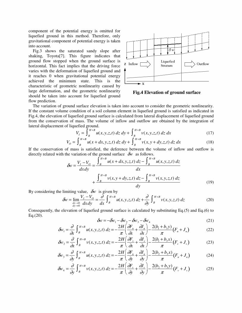
DISCONTINUOUS BOUNDARY The definition of lateral displacement and geometric configuration of liquefied subsoil contribute saving of computational time as mentioned in previous section. However, on the other hand, these conditions require the continuity of the geometric configuration in liquefied ground. However, this condition is sometimes incompatible with a situation of real ground. For example, if a foundation is deeper than the thickness of unsaturated surface crust as illustrated in Fig.5, the thickness of liquefied layer is irregular around the structure. Discontinuous boundary condition is presented to take the irregular into account by the conservation of mass. If the volume of flux is conserved between both side of the discontinuous boundary as illustrated in Fig.6, the following boundary condition is fulfilled. VL1 −VL 2 = 0 (34) in which,
VL1 = n ⋅U dz dlB
H +B
∫l∫ (35)
VL 2 = n ⋅U dz dl
B
H +B
∫l∫ (36)
U = u(x,y,z,t),v(x,y,z,t){ }t
(37)
Fig.5 Discontinuity of the thickness of liquefiable layer
Upstream Side
Downstream Side
Liquefieablelayer Liquefieable
layer
Boundary condition V L1=VL2
VL1 VL2
Fig.6 Discontinuous boundary

where VL1 and VL 2 are the influx volume of liquefied subsoil from liquefied ground to discontinuous boundary and the efflux volume from discontinuous boundary to liquefied ground, and n is a normal vector to the discontinuous boundary as shown in Fig.7. Note that exchange of potential energy between the both side of the discontinuous boundary is automatically considered since the conservation of mass is fulfilled.
SHEETPILE WALL Modeling of Sheet Pile Wall Sheet pile wall is modeled as an elastic bending slab to take its mitigative effect into account. If the displacement of the sheet pile wall is given by ρ , the boundary condition between the sheet pile wall and, upstream and downstream side of liquefied sand are derived from the conservation of mass as well as discontinuous boundary condition as indicated in Fig.8.
B1 = ξ1 n ⋅ U1 dzdlB1
H1 +B1∫l∫ − ρ dzdl
B1
H1 +B1∫l∫( ) (38)
B2 = ξ2 n ⋅ U2 dzdlB2
H2 +B2∫l∫ − ρ dzdl
B2
H2 +B2∫l∫( ) (39)
where ξ1 and ξ2 are Lagrangian multipliers, n is a vector which direction is normal to the sheet pile wall. These boundary conditions reveal that the volume of influx from liquefied subsoil is the same with the volume of the void that is generated by the deformation of the sheet pile. The strain energy of the sheet pile wall is given by the conventional theory of elastic beam.
1 1
1
22
2
1
2
H B
s p pl BE E I dzdl
z
∂ ρ∂
+ =
∫ ∫ (40)
By substituting the functional that is given as the summation of the Lagrangian and boundary conditions that are described as Eq.(38) and Eq.(39) to Lagrangian equation of motion, the consequent equation is given by
1 210
2l l l s
i i i i i i
K D P E B B
q q q q q q
∂ ∂ ∂ ∂ ∂ ∂∂ ∂ ∂ ∂ ∂ ∂
+ + + + + =&& &
(41)
For this equation of motion, ξ1, ξ2 and ρ j that are parameters to determine the shape of sheet pile
wall deformation are appended to the list of the generalized displacement qi to employ these boundary
Fig.8 Boundary condition for sheet pile wall model
Fig.7 Vector n for discontinuous boundary
nDiscontinuous
Boundary

condition. Consequently, following equation is fulfilled during ground flow.
1 1 2 2
1 21 2
1 2
10
2
H B H B
l B l Bl l l
i i i i i
n U dzdl n U dzdlK D P
q q q q q
∂ ∂∂ ∂ ∂ ξ ξ∂ ∂ ∂ ∂ ∂
+ +⋅ ⋅
+ + + + =∫ ∫ ∫ ∫
&& & (42)
∂B1
∂ξ1
= n ⋅ U1 dzdlB1
H1 +B1∫l∫ − ρ dzdl
B1
H1 +B1∫l∫ = 0 (43)
∂B2
∂ξ2
= n ⋅ U2 dzdlB2
H 2 +B2∫l∫ − ρ dzdl
B2
H 2 +B2∫l∫ = 0 (45)
∂Es
∂ρ j
+ ∂B1
∂ρ j
+ ∂B2
∂ρ j
= 0 (46)
By substituting Eq.(38), Eq.(39) and Eq.(40) to Eq.(46),
1 1 1 1 2 2
1 1 2
22
1 22
10
2
H B H B H B
p pl B l B l Bj j j
E I dzdl dzdl dzdlz
∂ ∂ ρ ∂ ∂ξ ρ ξ ρ∂ρ ∂ ∂ρ ∂ρ
+ + + − − =
∫ ∫ ∫ ∫ ∫ ∫ (47)
is obtained. This equation is developed by the integration by parts,
1 1 1 1
1 1
2 2 3
12 30
H B H B
p p p pl lj j jB B
E I dl E I dl Cz z z
∂ ρ ∂ ρ ∂ ρ ∂ρ ∂ρ∂ ∂ ∂ρ ∂ ∂ρ ∂ρ
+ +
− + = ∫ ∫ (48)
is given as an equivalent boundary condition. For Eq.(48), following boundary condition is employed by the conventional theory of elastic beam. ρ = 0 at z = B (49)
∂ρ∂z
= 0 at z = B (50)
2
20
z
∂ ρ∂
= at z = H + B (51)
3
30
z
∂ ρ∂
= at z = H + B (52)
Therefore,
1 1
1
42
1 1 241
0H B
p pl B
HC E I dzdl
z H
∂ ρ ξ ξ∂
+= − − =∫ ∫ (53)
is satisfied during the ground flow induced by liquefaction. Consequently,
4
21 24
1
1
p p
H
z E I H
∂ ρ ξ ξ∂
= +
(54)
is fulfilled as a boundary condition. This reveals that the lateral earth pressure that acts on a sheet pile wall is taken into account as homogeneous lateral pressure. In this case, the deformation shape of sheet pile wall in liquefied ground flow is able to be determined by only one parameter, for example, ρm that is the displacement of the top of the sheet pile wall.
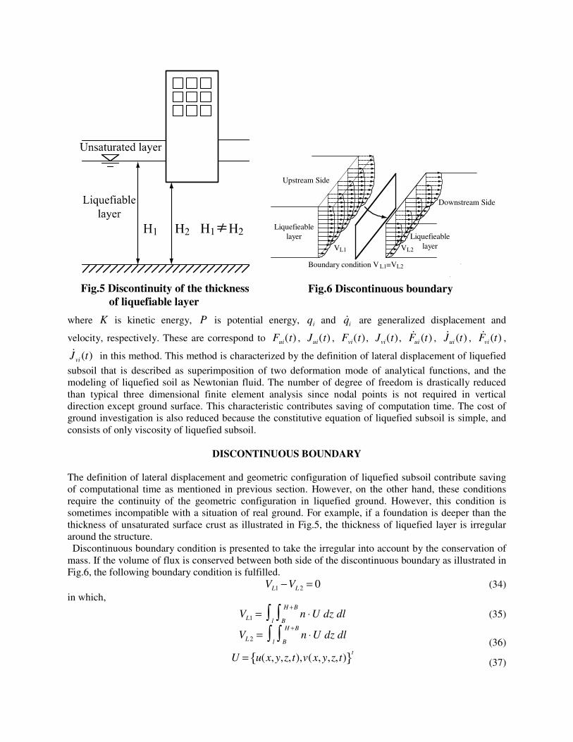
EXAMPLE ANALYSIS AND RESULTS Simple element test A series of example analysis for a simple model is carried out to check the mitigative effect of the sheet pile model. Fig.9 shows the model consists of two element, and a sheet pile wall is installed between the elements. The resultant deformation of the model is investigated by changing the bending stiffness of the
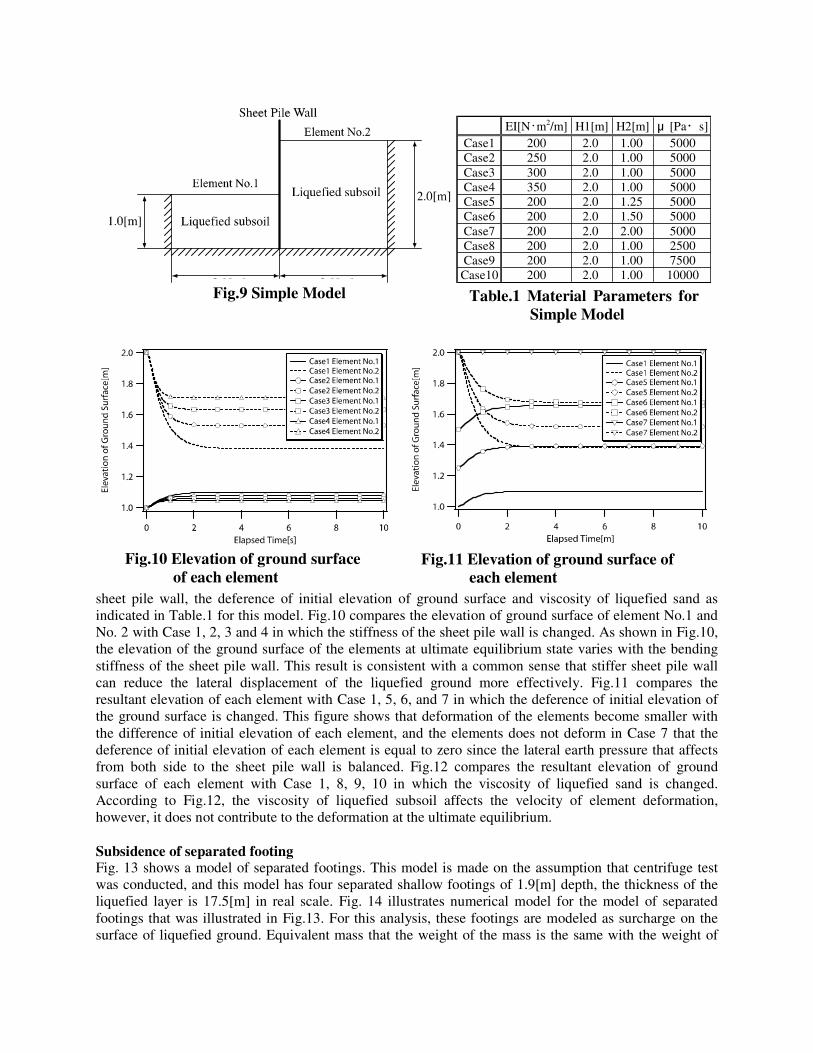
sheet pile wall, the deference of initial elevation of ground surface and viscosity of liquefied sand as indicated in Table.1 for this model. Fig.10 compares the elevation of ground surface of element No.1 and No. 2 with Case 1, 2, 3 and 4 in which the stiffness of the sheet pile wall is changed. As shown in Fig.10, the elevation of the ground surface of the elements at ultimate equilibrium state varies with the bending stiffness of the sheet pile wall. This result is consistent with a common sense that stiffer sheet pile wall can reduce the lateral displacement of the liquefied ground more effectively. Fig.11 compares the resultant elevation of each element with Case 1, 5, 6, and 7 in which the deference of initial elevation of the ground surface is changed. This figure shows that deformation of the elements become smaller with the difference of initial elevation of each element, and the elements does not deform in Case 7 that the deference of initial elevation of each element is equal to zero since the lateral earth pressure that affects from both side to the sheet pile wall is balanced. Fig.12 compares the resultant elevation of ground surface of each element with Case 1, 8, 9, 10 in which the viscosity of liquefied sand is changed. According to Fig.12, the viscosity of liquefied subsoil affects the velocity of element deformation, however, it does not contribute to the deformation at the ultimate equilibrium. Subsidence of separated footing Fig. 13 shows a model of separated footings. This model is made on the assumption that centrifuge test was conducted, and this model has four separated shallow footings of 1.9[m] depth, the thickness of the liquefied layer is 17.5[m] in real scale. Fig. 14 illustrates numerical model for the model of separated footings that was illustrated in Fig.13. For this analysis, these footings are modeled as surcharge on the surface of liquefied ground. Equivalent mass that the weight of the mass is the same with the weight of
Fig.9 Simple Model
Fig.10 Elevation of ground surface of each element
Fig.11 Elevation of ground surface of each element
Table.1 Material Parameters for Simple Model
EI[N・m2/m] H1[m] H2[m] μ [Pa・s]Case1 200 2.0 1.00 5000Case2 250 2.0 1.00 5000Case3 300 2.0 1.00 5000Case4 350 2.0 1.00 5000Case5 200 2.0 1.25 5000Case6 200 2.0 1.50 5000Case7 200 2.0 2.00 5000Case8 200 2.0 1.00 2500Case9 200 2.0 1.00 7500Case10 200 2.0 1.00 10000

the footings and tower is added to consider the inertia force of the footing and superstructure. Table. 2 shows the parameters that are employed for this analysis. The mass density of liquefied subsoil is decided as 1900[kg/m3] that is typical mass density of liquefied subsoil, and the viscosity of the liquefied subsoil was determined by referring to the results of element test, Chaminda[8]. The surcharge is calculated by assuming that the dead weight of a footings and superstructure is distributed homogeneously at the bottom of the footings. This is noteworthy that there is a discontinuity of the thickness of liquefiable layer between under the footings and the others. This discontinuity of the thickness of liquefiable layer is absorbed by discontinuous boundary condition that are presented in previous section. Fig.15 shows the time history of footing subsidence. It is note that the subsidence of each footing is the same in this model since this model is axi-symmetric for each footing as indicated in Fig.16. Therefore, one footing is picked up for investigation. According to Fig.15, the subsidence of the footing is extremely large in this case since the footing subsides until the buoyancy at the bottom of a footing is balance with the dead weight of the footing and tower. And the viscosity of liquefied subsoil contributes only the velocity of subsidence as well.
Fig.13 Target model
Fig.14 Numerical model for separated footings
Footing
Fig.12 Elevation of ground surface of eachelement
Table.2 Material Property for the centrifuge model
Mass Density[kg/m3] Viscosity[kPa・s]Case1 1900 50000Case2 1900 100000Case3 1900 150000Case4 1900 200000

Subsidence of connected footing The deformation of liquefied ground is large deformation problem, and geometric nonlinearity is important for the prediction of the deformation as stated. In a previous section, the subsidence of the separated footing was investigated, and the equilibrium was achieved when the buoyancy is equal to the total dead weight of the footing and the tower. This result suggests that the subsidence is able to be reduced if the buoyancy per unit subsidence is increased. As a way to increase the buoyancy to the footing, the enlargement of the cross section of footing by soil solidification at the surface of liquefied ground which connects all footings is considered. Fig.17 shows the mesh for connected footing model. For this model, the circle area was defined for the area of ground improvement and it is assumed that the total weight of footings and tower is distributed homogeneously on the ground surface of the improved area. The equivalent mass is installed to consider the inertia force of footings, tower and soils that are solidification as well. Fig.18 compares the time history of the subsidence of the connected footing and the separated footing. According to Fig.18, the subsidence of the footings is drastically reduced by the soil
Fig.15 Time history of separated footing subsidence
Soil Solidification Area
Fig.17 Numerical model for connected footing
Fig.16 Contour of uplift of ground after 20[s]
Fig.18 Comparison of separated footing and connected footing
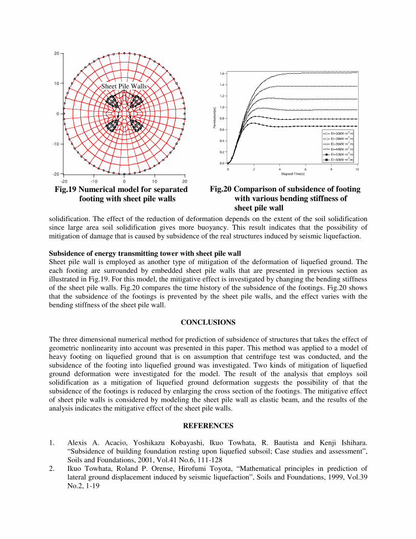
solidification. The effect of the reduction of deformation depends on the extent of the soil solidification since large area soil solidification gives more buoyancy. This result indicates that the possibility of mitigation of damage that is caused by subsidence of the real structures induced by seismic liquefaction. Subsidence of energy transmitting tower with sheet pile wall Sheet pile wall is employed as another type of mitigation of the deformation of liquefied ground. The each footing are surrounded by embedded sheet pile walls that are presented in previous section as illustrated in Fig.19. For this model, the mitigative effect is investigated by changing the bending stiffness of the sheet pile walls. Fig.20 compares the time history of the subsidence of the footings. Fig.20 shows that the subsidence of the footings is prevented by the sheet pile walls, and the effect varies with the bending stiffness of the sheet pile wall.
CONCLUSIONS The three dimensional numerical method for prediction of subsidence of structures that takes the effect of geometric nonlinearity into account was presented in this paper. This method was applied to a model of heavy footing on liquefied ground that is on assumption that centrifuge test was conducted, and the subsidence of the footing into liquefied ground was investigated. Two kinds of mitigation of liquefied ground deformation were investigated for the model. The result of the analysis that employs soil solidification as a mitigation of liquefied ground deformation suggests the possibility of that the subsidence of the footings is reduced by enlarging the cross section of the footings. The mitigative effect of sheet pile walls is considered by modeling the sheet pile wall as elastic beam, and the results of the analysis indicates the mitigative effect of the sheet pile walls.
REFERENCES 1. Alexis A. Acacio, Yoshikazu Kobayashi, Ikuo Towhata, R. Bautista and Kenji Ishihara.
“Subsidence of building foundation resting upon liquefied subsoil; Case studies and assessment”, Soils and Foundations, 2001, Vol.41 No.6, 111-128
2. Ikuo Towhata, Roland P. Orense, Hirofumi Toyota, “Mathematical principles in prediction of lateral ground displacement induced by seismic liquefaction”, Soils and Foundations, 1999, Vol.39 No.2, 1-19
Fig.19 Numerical model for separatedfooting with sheet pile walls
Sheet Pile Walls
Fig.20 Comparison of subsidence of footing with various bending stiffness of sheet pile wall

3. Satoshi Nishimura, Ikuo Towhata and Tsuyoshi Honda, “Laboratory shear tests on viscous nature of liquefied sand”, Soils and Foundations, 2002, Vol.42 No.4, 89-98
4. I. Towhata, W. Vargas-Monge, R. P. Orense, M. Yao, “Shaking table tests on subgrade reaction of pipe embedded in sandy liquefied subsoil”, Soil Dynamics and Earthquake Engineering, 1999, 18, 347-361
5. Yasushi Sasaki, Ikuo Towhata, Ken-Ichi Tokida, Kazuhiro Yamada, Hideo Matsumoto and Yukio Tamari, “Mechanism of permanent displacement of ground caused by seismic liquefaction”, Soils and Foundations, 1992, Vol32 No.3, 79-96
6. Hirofumi Toyota, “Shaking table tests and analytical prediction on lateral flow of liquefied ground”, Ph.D thesis, 1995, Department of Civil Engineering, School of Engineering, The University of Tokyo
7. Mizutani, T., Towhata, I., Shinkawa, N., Ibi, S., Komatsu, T., and Nagai, T,. ”Shaking table tests on mitigation of liquefaction-induced subsidence of river dikes”, Proc. 16th ICSMGE, Istanbul, 2001, Vol2, 1207-1210
8. Chaminda. P. K. Gallge, “Laboratory shear tests on rate dependant nature of liquefied sand with fines”, Master thesis, 2002, Department of Civil Engineering, The University of Tokyo