Threaded Connectors for Sandwich Pipes – Part 2 ...
16
1 Threaded Connectors for Sandwich Pipes – Part 2: Optimisation of Stress Relief Groove Ikechukwu Onyegiri, Maria Kashtalyan* Centre for Micro- and Nanomechanics (CEMINACS), School of Engineering, University of Aberdeen, Fraser Noble Building, Aberdeen AB24 3UE *Corresponding author: [email protected] Abstract A concept for using snap-fit connectors in sandwich pipes is investigated numerically in two companion papers using a combination of 2D axisymmetric and 3D finite element models in Abaqus. In the Part 1 paper, results of key parametric studies related to the installation analysis of sandwich pipes in deepwater are reported. The modification of the nib groove to include variable radii, the use of an elastomeric seal coupled with compressive pre-stress and an optimum resin-to-core ratio all proved to enhance the performance of the sandwich pipe snap-fit connectors. The influence of the interlayer adhesion configuration on the stress concentration experienced in the connector is also studied. Furthermore, a comparative study is performed to investigate the mechanical behaviour of the snap-fit connector concept in sandwich pipes and conventional pipe-in-pipe. In the Part 2 paper, an optimisation study is carried out for the stress relief groove (SRG) in the pin of the snap-fit connector. A combined parameter is proposed to capture the relationship between the investigated geometric properties and the stress concentration factor at the SRG. It is established that the fillet radius could indeed be used to offset the drop in performance associated with increasing the SRG depth while improving the fatigue characteristics of the connector threads. Keywords Pipe joining, finite element modelling, snap-fit connector
Transcript of Threaded Connectors for Sandwich Pipes – Part 2 ...
1
Threaded Connectors for Sandwich Pipes – Part 2: Optimisation of Stress Relief Groove
Ikechukwu Onyegiri, Maria Kashtalyan*
Centre for Micro- and Nanomechanics (CEMINACS), School of Engineering, University of Aberdeen,
Fraser Noble Building, Aberdeen AB24 3UE
*Corresponding author: [email protected]
Abstract A concept for using snap-fit connectors in sandwich pipes is investigated numerically in two
companion papers using a combination of 2D axisymmetric and 3D finite element models in Abaqus.
In the Part 1 paper, results of key parametric studies related to the installation analysis of sandwich
pipes in deepwater are reported. The modification of the nib groove to include variable radii, the use
of an elastomeric seal coupled with compressive pre-stress and an optimum resin-to-core ratio all
proved to enhance the performance of the sandwich pipe snap-fit connectors. The influence of the
interlayer adhesion configuration on the stress concentration experienced in the connector is also
studied. Furthermore, a comparative study is performed to investigate the mechanical behaviour of
the snap-fit connector concept in sandwich pipes and conventional pipe-in-pipe.
In the Part 2 paper, an optimisation study is carried out for the stress relief groove (SRG) in the pin of
the snap-fit connector. A combined parameter is proposed to capture the relationship between the
investigated geometric properties and the stress concentration factor at the SRG. It is established
that the fillet radius could indeed be used to offset the drop in performance associated with
increasing the SRG depth while improving the fatigue characteristics of the connector threads.
Keywords Pipe joining, finite element modelling, snap-fit connector

2
1. Introduction Threaded and coupled (T&C) connectors have been utilised in offshore oil pipelines with a good
track record and serve economically well especially in shallow waters. They can be viewed as an
alternative joining method for pipelines and risers in deepwater, where increased wall thickness and
use of high strength steels could make welding a less favourable option.
It is well known that seal integrity and uniform stress distribution along the thread roots remain key
challenges for threaded connectors especially when placed under severe bending loads (Sches et al.
2008). There exist a wide variety of “qualified” improvements to the conventional T&C connector,
mainly driven by enhanced mechanical performance for its use in risers, drill pipes and tendons.
These improvements range from local to global geometrical modifications and a few are discussed in
this paper. All improved designs seek to tackle a number of operational challenges depending on the
joint requirements. The reduction of high local stresses and a more uniform stress distribution along
the joint remain design priorities which when optimised lead to a better fatigue resistant
connection.
This paper aims to identify the fatigue critical regions for a snap-fitted sandwich pipe and explore
modifications to reduce the stress concentration in such regions. The relationship between the
stress concentration at these regions and the connection’s mechanical/geometrical properties is
investigated for typical installation loads (bending, external pressure and axial loading). The
formulation of optimization parameters to predict connection performance via parametric finite
element analysis in Abaqus (Dassault Systèmes 2014) is also studied, in particular geometrical
properties of the nib groove (considered in the Part 1 paper) and stress relief groove (considered in
the present Part 2 paper). A better understanding of the added complexities to the snap-fit
connector for its utilization in sandwich pipes is gained from the results from this study. As a
complex multiaxial stress distribution is expected over the connection, the maximum principal stress
is used.
2. Trends in Connector Improvement A large variety of patented improvements to threaded and coupled pipe connectors follows two
general trends, namely: modifications to the joint global geometry, (DeLange et al. 2003), (Verdillon
2004) and modifications to the thread profile, (Gunderson et al. 1990), (DeLange et al. 1999),
(Flemming 2004),(Noel and Roussie 2004).
3
Under installation loads, a conventional threaded connection will have peak stresses located at the
root of the first engaged thread (FET) of the pin and last engaged thread (LET) of the box (Tafreshi
1999).
Local stiffness reduction to enhance uniform loading in the joint has been utilised in most solutions
with numerical and experimental tests documented to verify. This approach is guided by easing the
transfer of load between joint components at identified regions of local high stresses. (Bodine 1961)
utilised this approach by applying a groove at the outer surface of the coupler box which is radially
aligned with the LET of the pin. This would lead to a reduction in stiffness around that section, thus
making it easier to deform elastically and transfer load more uniformly across the joint length.
Longer engaged threads were proposed by both (DeLange et al. 2003) and (Verdillon 2004) with
modifications to include thread run-out allowing for partial engagement of threads. This allows for
some level of stress redistribution around the LET and as thus reduces the high local stresses that
would normally have occurred.
It is well known that modifying the thread profile (especially at the root), could lead to an optimal
design to reduce unwanted high stress regions in the connection. A conventional thread profile is
defined by its height, flank angle, root groove finishing, pitch, load flank interference and fabrication
tolerances, ASME B1.20.1(2013); leading to a pool of variables to combine in aim of arriving at an
optimal design. This is no mean feat as some designs although showing an improvement in fatigue
properties for the connector, require unattainable fabrication tolerances at that scale, (Van
Wittenberghe et al. 2011). This creates a hurdle for this approach from an economic and technical
point of view.
Nevertheless, significant improvements have been made to standard thread profiles. Take for
instance, an early modification by (Saunders et al. 1985) which adopted a larger radii and stress
relief groove at the root coupled with a modified pin profile pitch to improve load distribution via
radial interference. (DeLange et al. 2003) took the approach of designing with a zero degree load
flank and increased root radii with the goal of significantly reducing the radial component which
contributes to pin-box thread separation. (Banker et al. 1994) patented an improved fatigue
connector with load flanks having rounded corners while also designing the thread profile with a
negative load flank which through research by (Takano et al. 2002) showed improved resistance to
plastic yielding, galling and increased tensile, bending and external pressure capacity. Modifications
by (Noel and Roussie 2004) took the approach of grooving the FET and LET of a buttress type thread
in aim of reducing the stiffness and creating multiple stress zones which in turn improves load
distribution around the FET and LET region. (Nakamura et al. 2011) modified their design by using
4
two-step stabbing flanks for the threads in aim of improving pin insertion and galling resistance.
(Sches et al. 2008) came up with a threaded profile, in which the gap between the loading and
stabbing flanks was closed, increased the root radii, increased the chamfer angle on the stabbing
flank and moved surface contact from the pin thread root. The resulting profile was reported to be
able to isolate the effects of fretting from the effects of fatigue loading.
Another proven approach to improving connector performance is the inclusion of stress relief
features in the joint geometry. According to API 7-1 (2006), stress relief features can be described as
“a modification performed on rotary shouldered connections by removing the unengaged threads
on the pin or box to make the joint more flexible and to reduce the likelihood of fatigue-cracking in
highly stressed areas”. The two most common features are: the stress relief groove (SRG) and the
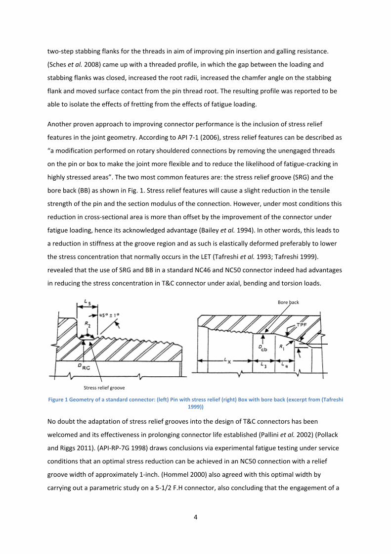
bore back (BB) as shown in Fig. 1. Stress relief features will cause a slight reduction in the tensile
strength of the pin and the section modulus of the connection. However, under most conditions this
reduction in cross-sectional area is more than offset by the improvement of the connector under
fatigue loading, hence its acknowledged advantage (Bailey et al. 1994). In other words, this leads to
a reduction in stiffness at the groove region and as such is elastically deformed preferably to lower
the stress concentration that normally occurs in the LET (Tafreshi et al. 1993; Tafreshi 1999).
revealed that the use of SRG and BB in a standard NC46 and NC50 connector indeed had advantages
in reducing the stress concentration in T&C connector under axial, bending and torsion loads.
Figure 1 Geometry of a standard connector: (left) Pin with stress relief (right) Box with bore back (excerpt from (Tafreshi 1999))
No doubt the adaptation of stress relief grooves into the design of T&C connectors has been
welcomed and its effectiveness in prolonging connector life established (Pallini et al. 2002) (Pollack
and Riggs 2011). (API-RP-7G 1998) draws conclusions via experimental fatigue testing under service
conditions that an optimal stress reduction can be achieved in an NC50 connection with a relief
groove width of approximately 1-inch. (Hommel 2000) also agreed with this optimal width by
carrying out a parametric study on a 5-1/2 F.H connector, also concluding that the engagement of a
Bore back
Stress relief groove
5
partial box thread rather than a full thread with the LET of the pin has a significant advantage by
lowering the stress in that section of the pin.
It should be emphasized at this point that although T&C connector design is properly standardised
for drill pipes and to some extent for risers, when it comes to its application for oil and gas pipelines,
proprietary joint types rule the market space. Some would argue that this is due to the uniqueness
of multiphase oil and gas transport and flow conditions while some would blame it on a weightier
industry confidence on welding as a preferred joining method for pipelines. This on the other hand
has helped forge a new business line for joint designers who seek to develop new and modified
systems to make economic profit. At the moment, threaded connectors for flowlines are certified by
ISO 21329 (2004) and follow strict adherence to operational health and safety.
3. Stress Relief Groove It is well known from standards (API-RP-7G 1998) and numerical analysis (Tafreshi et al. 1993)
(Tafreshi 1999) (Hommel 2000) (Pallini et al. 2002) that the stress relief groove and bore back
represent an effective modification to threaded line pipe joints leading to improved fatigue
performance and prolonged connector life. The pathway to this solution involves reducing the
maximum SCF in the connector which is generally known to be at the LET of the pin threads. The
influence of this solution at the critical LET of the pin as can be seen in Fig. 6a of the Part 1 paper;
this was also adopted in the snap-fit connector design for sandwich pipes. For elastic analysis, the
truncation height for the connector threads had no significant effect on the SCF at the thread roots
as the SCF was calculated as a function of the root diameter.
The stress relief groove design for an 8-inch threaded pipe is shown in Fig.2a. To achieve geometric
convergence some dimensions were made consistent with (ASME B1.20.12013) standard dimensions
or derived as function of such dimensions. The essential geometric parameters describing the stress
relief groove to be used in this study are shown in Fig. 2b.
6
10 47’ taper,θp
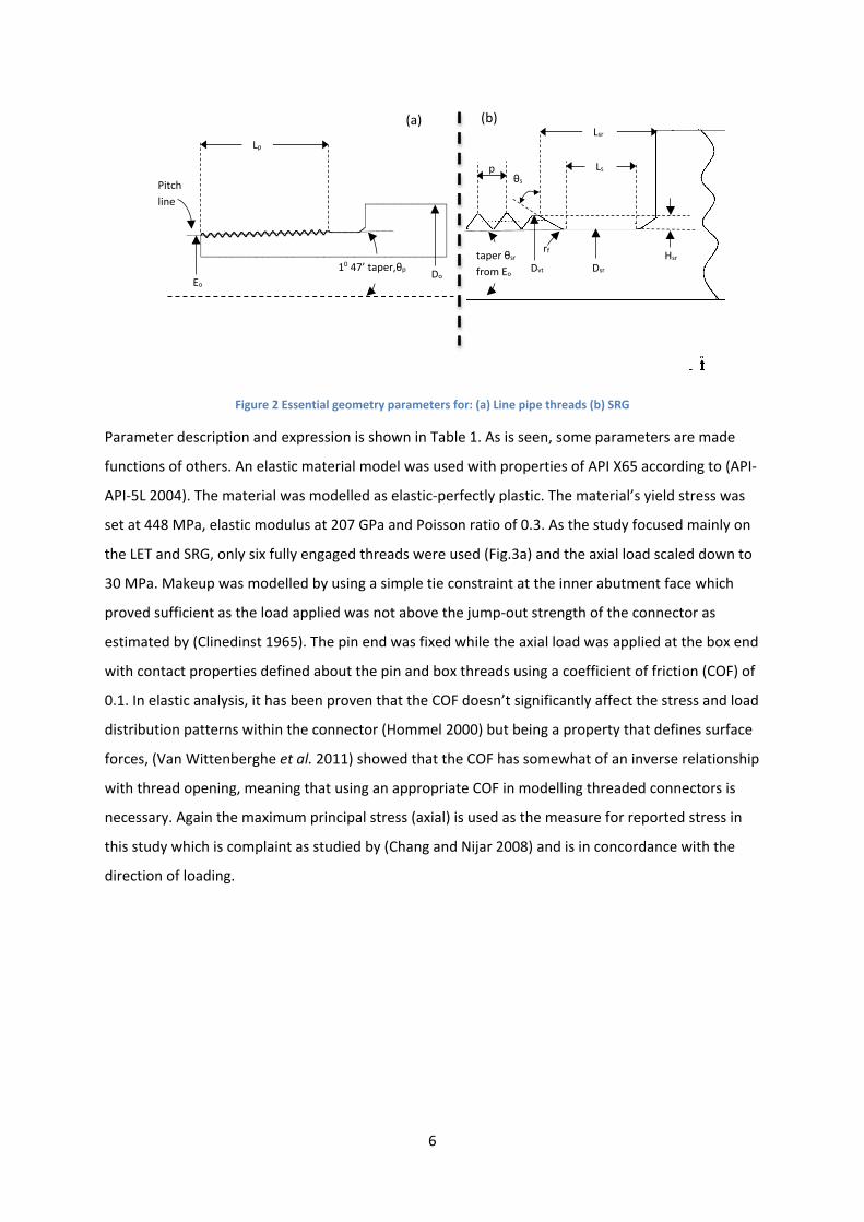
Figure 2 Essential geometry parameters for: (a) Line pipe threads (b) SRG
Parameter description and expression is shown in Table 1. As is seen, some parameters are made
functions of others. An elastic material model was used with properties of API X65 according to (API-
API-5L 2004). The material was modelled as elastic-perfectly plastic. The material’s yield stress was
set at 448 MPa, elastic modulus at 207 GPa and Poisson ratio of 0.3. As the study focused mainly on
the LET and SRG, only six fully engaged threads were used (Fig.3a) and the axial load scaled down to
30 MPa. Makeup was modelled by using a simple tie constraint at the inner abutment face which
proved sufficient as the load applied was not above the jump-out strength of the connector as
estimated by (Clinedinst 1965). The pin end was fixed while the axial load was applied at the box end
with contact properties defined about the pin and box threads using a coefficient of friction (COF) of
0.1. In elastic analysis, it has been proven that the COF doesn’t significantly affect the stress and load
distribution patterns within the connector (Hommel 2000) but being a property that defines surface
forces, (Van Wittenberghe et al. 2011) showed that the COF has somewhat of an inverse relationship
with thread opening, meaning that using an appropriate COF in modelling threaded connectors is
necessary. Again the maximum principal stress (axial) is used as the measure for reported stress in
this study which is complaint as studied by (Chang and Nijar 2008) and is in concordance with the
direction of loading.
Eo Do
Lp
Pitch line
Dsr
Lsr
Ls
taper θsr from Eo
rf
Dvt Hsr
p θs
(a) (b)
7
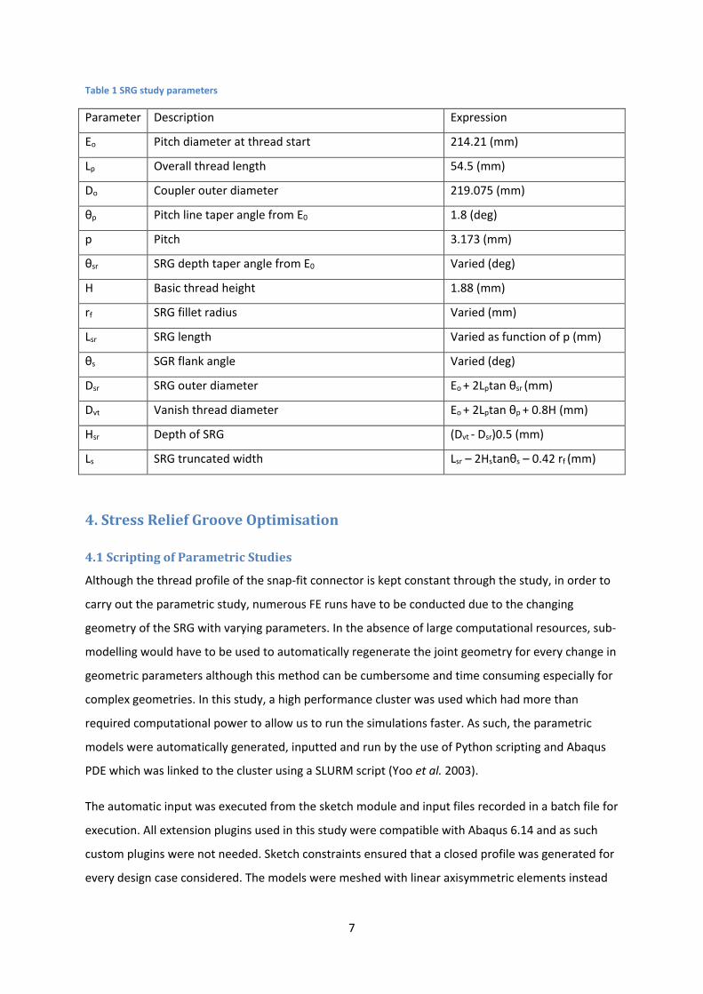
Table 1 SRG study parameters
Parameter Description Expression
Eo Pitch diameter at thread start 214.21 (mm)
Lp Overall thread length 54.5 (mm)
Do Coupler outer diameter 219.075 (mm)
θp Pitch line taper angle from E0 1.8 (deg)
p Pitch 3.173 (mm)
θsr SRG depth taper angle from E0 Varied (deg)
H Basic thread height 1.88 (mm)
rf SRG fillet radius Varied (mm)
Lsr SRG length Varied as function of p (mm)
θs SGR flank angle Varied (deg)
Dsr SRG outer diameter Eo + 2Lptan θsr (mm)
Dvt Vanish thread diameter Eo + 2Lptan θp + 0.8H (mm)
Hsr Depth of SRG (Dvt - Dsr)0.5 (mm)
Ls SRG truncated width Lsr – 2Hstanθs – 0.42 rf (mm)
4. Stress Relief Groove Optimisation
4.1 Scripting of Parametric Studies
Although the thread profile of the snap-fit connector is kept constant through the study, in order to
carry out the parametric study, numerous FE runs have to be conducted due to the changing
geometry of the SRG with varying parameters. In the absence of large computational resources, sub-
modelling would have to be used to automatically regenerate the joint geometry for every change in
geometric parameters although this method can be cumbersome and time consuming especially for
complex geometries. In this study, a high performance cluster was used which had more than
required computational power to allow us to run the simulations faster. As such, the parametric
models were automatically generated, inputted and run by the use of Python scripting and Abaqus
PDE which was linked to the cluster using a SLURM script (Yoo et al. 2003).
The automatic input was executed from the sketch module and input files recorded in a batch file for
execution. All extension plugins used in this study were compatible with Abaqus 6.14 and as such
custom plugins were not needed. Sketch constraints ensured that a closed profile was generated for
every design case considered. The models were meshed with linear axisymmetric elements instead
8
of quadratic elements due to the existence of contact non-linearity between the threads for this
study (Chang and Nijar 2008). For contact non-linearity in Abaqus, the greater the number of
adjusted nodes and their relative displacements, the more likely the convergence issues. Although
second order elements provide higher accuracy, for contact conditions with severe element
distortion, the mid-nodes can generate abnormal stress patterns within the element integration
points. The trade-off being the generation of large number of elements to avoid convergence issues.
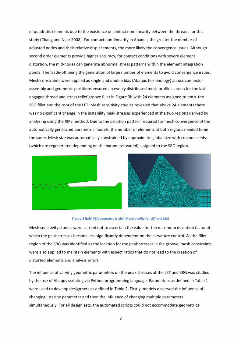
Mesh constraints were applied as single and double bias (Abaqus terminology) across connector
assembly and geometric partitions ensured an evenly distributed mesh profile as seen for the last
engaged thread and stress relief groove fillet in Figure 3b with 24 elements assigned to both the
SRG fillet and the root of the LET. Mesh sensitivity studies revealed that above 24 elements there
was no significant change in the instability peak stresses experienced at the two regions derived by
analysing using the RIKS method. Due to the partition pattern required for mesh convergence of the
automatically generated parametric models, the number of elements at both regions needed to be
the same. Mesh size was automatically constrained by approximate global size with custom seeds
(which are regenerated depending on the parameter varied) assigned to the SRG region.
Figure 3 (left) FEA geometry (right) Mesh profile for LET and SRG
Mesh sensitivity studies were carried out to ascertain the value for the maximum deviation factor at
which the peak stresses became less significantly dependent on the curvature control. As the fillet
region of the SRG was identified as the location for the peak stresses in the groove, mesh constraints
were also applied to maintain elements with aspect ratios that do not lead to the creation of
distorted elements and analysis errors.
The influence of varying geometric parameters on the peak stresses at the LET and SRG was studied
by the use of Abaqus scripting via Python programming language. Parameters as defined in Table 1
were used to develop design sets as defined in Table 2. Firstly, models observed the influence of
changing just one parameter and then the influence of changing multiple parameters
simultaneously. For all design sets, the automated scripts could not accommodate geometrical
9
functions created by varying more than three parameters. Multiple constraints had to be adopted in
the geometry sketch files to restrict dimensions within the set functions and resolve geometrical
convergence problems.
Table 2 Design sets and defining parameters
Design set 1 2 3 4 5
Varied Lsr θsr θs rf θsr , rf
Fixed θsr ,rf , θs Lsr , rf , θs Lsr , rf , θsr Lsr , θs , θsr Lsr , θs
From a geometric perspective, the depth and length of the SRG are arguably the most critical
parameters when it comes to the magnitude of peak stresses. Increasing the depth of the SRG will
reduce its wall thickness which will in turn increase the magnitude of peak stress. From study carried
out by (Hommel 2000), it was found that indeed an optimal length exists for the SRG; lengths shorter
than optimal introduced further stress concentrations while lengths longer than optimal have a
tendency to load up the LET excessively. In order to reduce the number of studied parameters for
geometric convergence, some variables were made a function of others as seen in Table 1. The
maximum stresses in the SRG always occurred at the fillet and there existed in most models an
inverse relationship between the peak stresses at the fillet of the SRG and the peak stresses at the
root of the LET of the pin. Two pipe sizes (6-inch and 8-inch) were considered in this study. The
models adopted to investigate the effect of make-up (8-inch only) for this study were modified to
have a larger pin outer diameter after the SRG termination. This was done to create a pin shoulder
for the simulation of makeup. From the analysis results presented below, we can see the influence
of the shoulder on the SCF. For example, in Fig.4, we notice that the SCF of the no makeup case in
(b) is lower than that of the 8-inch model in (a).
4.2 Influence of Groove Depth
The influence of the groove depth, Hsr on the peak stresses was studied by varying the SRG depth
taper angle (from Eo) θsr. As expected, an increase in the depth of the groove increases the
magnitude of peak stress in the SRG for both the 6-inch and 8-inch models as seen in Fig.4a. The
length, fillet radius and flank angle of the SRG are kept constant for this design set. θsr was varied
from 2.0o to -0.9o from Eo and the corresponding groove depth computed by the expression in Table
1. From analysis result, keeping the SRG depth to a minimum would be a preferred solution to
10
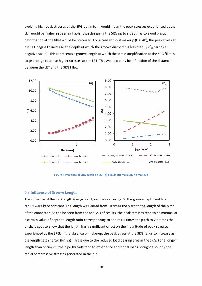
avoiding high peak stresses at the SRG but in turn would mean the peak stresses experienced at the
LET would be higher as seen in Fig.4a, thus designing the SRG up to a depth as to avoid plastic
deformation at the fillet would be preferred. For a case without makeup (Fig. 4b), the peak stress at
the LET begins to increase at a depth at which the groove diameter is less than Eo (θsr carries a
negative value). This represents a groove length at which the stress amplification at the SRG fillet is
large enough to cause higher stresses at the LET. This would clearly be a function of the distance
between the LET and the SRG fillet.
Figure 4 Influence of SRG depth on SCF (a) 8in,6in (b) Makeup, No makeup
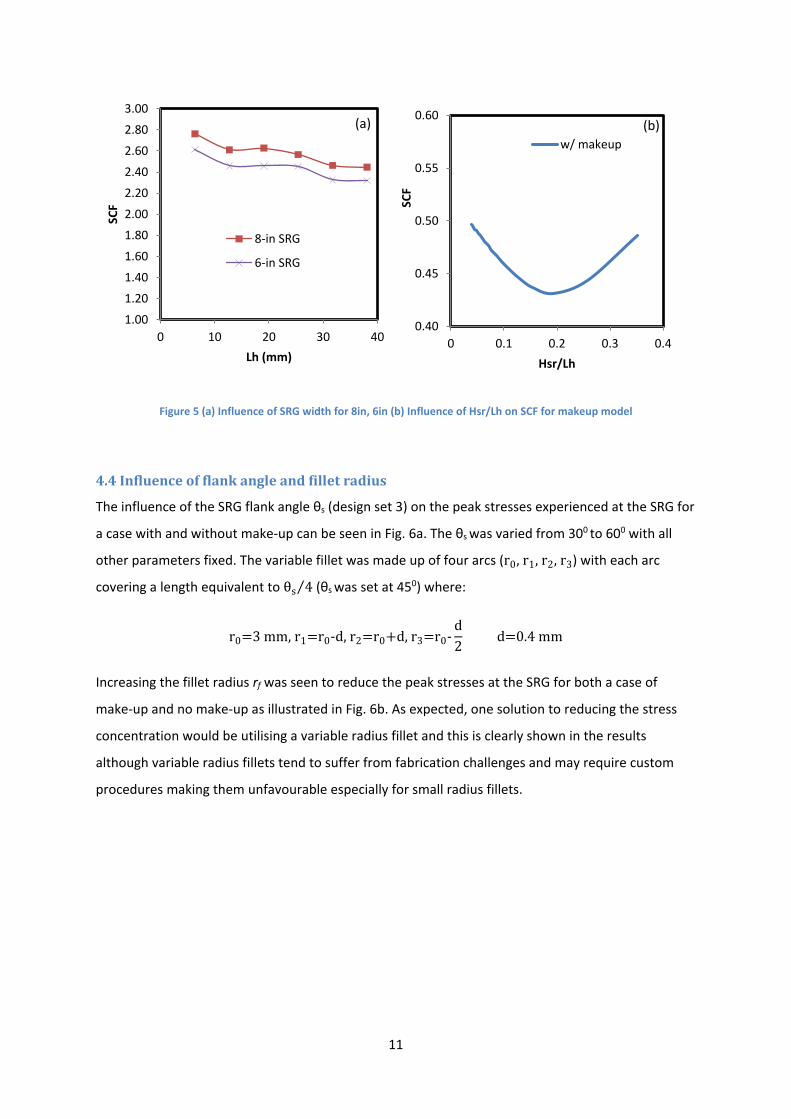
4.3 Influence of Groove Length
The influence of the SRG length (design set 1) can be seen in Fig. 5. The groove depth and fillet
radius were kept constant. The length was varied from 10 times the pitch to the length of the pitch
of the connector. As can be seen from the analysis of results, the peak stresses tend to be minimal at
a certain value of depth to length ratio corresponding to about 1.5 times the pitch to 2.5 times the
pitch. It goes to show that the length has a significant effect on the magnitude of peak stresses
experienced at the SRG. In the absence of make-up, the peak stress at the SRG tends to increase as
the length gets shorter (Fig.5a). This is due to the reduced load bearing area in the SRG. For a longer
length than optimum, the pipe threads tend to experience additional loads brought about by the
radial compressive stresses generated in the pin.
0.00
2.00
4.00
6.00
8.00
10.00
12.00
0 1 2 3
SCF
Hsr (mm)
8-inch LET 8-inch SRG
6-inch LET 6-inch SRG
0.00
1.00
2.00
3.00
4.00
5.00
6.00
7.00
8.00
9.00
0 1 2 3
SCF
Hsr (mm)
w/ MakeUp - SRG w/o MakeUp - SRG
w/MakeUp - LET w/o MakeUp - LET
(a) (b)
11
Figure 5 (a) Influence of SRG width for 8in, 6in (b) Influence of Hsr/Lh on SCF for makeup model
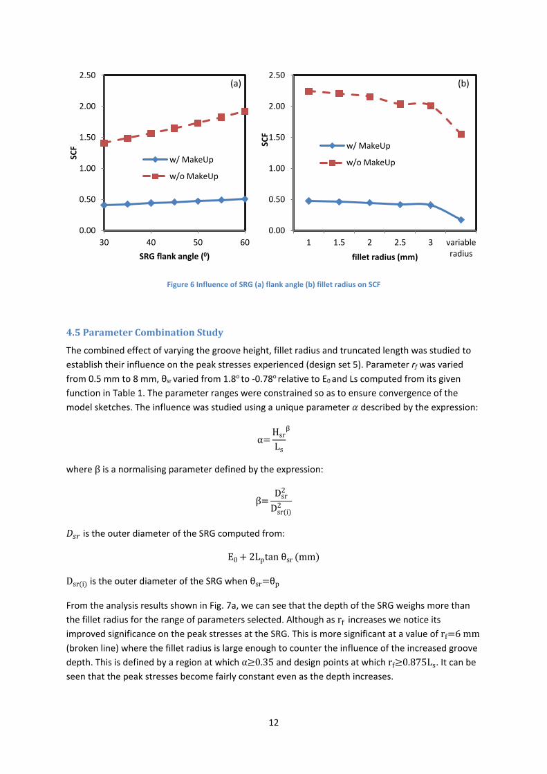
4.4 Influence of flank angle and fillet radius
The influence of the SRG flank angle θs (design set 3) on the peak stresses experienced at the SRG for
a case with and without make-up can be seen in Fig. 6a. The θs was varied from 300 to 600 with all
other parameters fixed. The variable fillet was made up of four arcs (r0, r1, r2, r3) with each arc
covering a length equivalent to θs 4⁄ (θs was set at 450) where:
r0=3 mm, r1=r0-d, r2=r0+d, r3=r0-d2
d=0.4 mm
Increasing the fillet radius rf was seen to reduce the peak stresses at the SRG for both a case of
make-up and no make-up as illustrated in Fig. 6b. As expected, one solution to reducing the stress
concentration would be utilising a variable radius fillet and this is clearly shown in the results
although variable radius fillets tend to suffer from fabrication challenges and may require custom
procedures making them unfavourable especially for small radius fillets.
1.00
1.20
1.40
1.60
1.80
2.00
2.20
2.40
2.60
2.80
3.00
0 10 20 30 40
SCF
Lh (mm)
8-in SRG
6-in SRG
0.40
0.45
0.50
0.55
0.60
0 0.1 0.2 0.3 0.4
SCF
Hsr/Lh
w/ makeup(a) (b)
12
Figure 6 Influence of SRG (a) flank angle (b) fillet radius on SCF
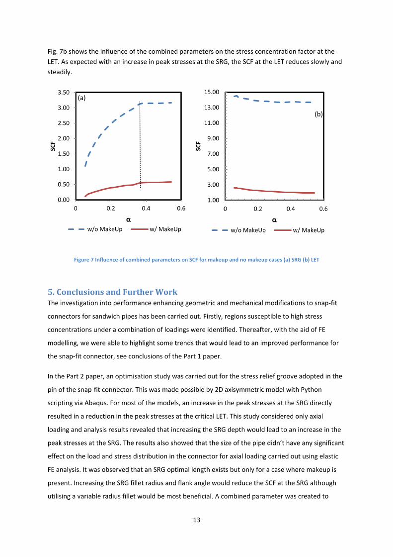
4.5 Parameter Combination Study
The combined effect of varying the groove height, fillet radius and truncated length was studied to establish their influence on the peak stresses experienced (design set 5). Parameter rf was varied from 0.5 mm to 8 mm, θsr varied from 1.8o to -0.78o relative to E0 and Ls computed from its given function in Table 1. The parameter ranges were constrained so as to ensure convergence of the model sketches. The influence was studied using a unique parameter 𝛼𝛼 described by the expression:
α=Hsr
Ls
β
where β is a normalising parameter defined by the expression:
β=Dsr
2
Dsr(i)2
𝐷𝐷𝑠𝑠𝑟𝑟 is the outer diameter of the SRG computed from:
E0 + 2Lptan θsr (mm)
Dsr(i) is the outer diameter of the SRG when θsr=θp
From the analysis results shown in Fig. 7a, we can see that the depth of the SRG weighs more than the fillet radius for the range of parameters selected. Although as rf increases we notice its improved significance on the peak stresses at the SRG. This is more significant at a value of rf=6 mm (broken line) where the fillet radius is large enough to counter the influence of the increased groove depth. This is defined by a region at which α≥0.35 and design points at which rf≥0.875Ls. It can be seen that the peak stresses become fairly constant even as the depth increases.
0.00
0.50
1.00
1.50
2.00
2.50
30 40 50 60
SCF
SRG flank angle (0)
w/ MakeUp
w/o MakeUp
0.00
0.50
1.00
1.50
2.00
2.50
1 1.5 2 2.5 3 variableradius
SCF
fillet radius (mm)
w/ MakeUp
w/o MakeUp
(a) (b)
13
Fig. 7b shows the influence of the combined parameters on the stress concentration factor at the LET. As expected with an increase in peak stresses at the SRG, the SCF at the LET reduces slowly and steadily.
Figure 7 Influence of combined parameters on SCF for makeup and no makeup cases (a) SRG (b) LET
5. Conclusions and Further Work The investigation into performance enhancing geometric and mechanical modifications to snap-fit
connectors for sandwich pipes has been carried out. Firstly, regions susceptible to high stress
concentrations under a combination of loadings were identified. Thereafter, with the aid of FE
modelling, we were able to highlight some trends that would lead to an improved performance for
the snap-fit connector, see conclusions of the Part 1 paper.
In the Part 2 paper, an optimisation study was carried out for the stress relief groove adopted in the
pin of the snap-fit connector. This was made possible by 2D axisymmetric model with Python
scripting via Abaqus. For most of the models, an increase in the peak stresses at the SRG directly
resulted in a reduction in the peak stresses at the critical LET. This study considered only axial
loading and analysis results revealed that increasing the SRG depth would lead to an increase in the
peak stresses at the SRG. The results also showed that the size of the pipe didn’t have any significant
effect on the load and stress distribution in the connector for axial loading carried out using elastic
FE analysis. It was observed that an SRG optimal length exists but only for a case where makeup is
present. Increasing the SRG fillet radius and flank angle would reduce the SCF at the SRG although
utilising a variable radius fillet would be most beneficial. A combined parameter was created to
0.00
0.50
1.00
1.50
2.00
2.50
3.00
3.50
0 0.2 0.4 0.6
SCF
αw/o MakeUp w/ MakeUp
1.00
3.00
5.00
7.00
9.00
11.00
13.00
15.00
0 0.2 0.4 0.6
SCF
αw/o MakeUp w/ MakeUp
(a)
(b)

14
capture the relationship between the investigated geometric properties and the SCF at the SRG and
it was discovered that the fillet radius could indeed be used to offset the drop in performance
associated with increasing the SRG depth. The design point at which this happens was found to be at
rf≥0.875Ls and a combined parameter value greater than or equal to 0.35. This analysis was carried
out using an 8 in API threaded line pipe and further work will have to be carried out to validate the
study for other line sizes. Future work is planned to carry out this study under pure bending and
combined loading to get a better understanding the influence of the SRG geometry on the joint
performance.
Acknowledgements The authors would like to acknowledge the financial support of the University of Aberdeen, through
the Elphinstone PhD studentship, and the support of the Maxwell computer cluster funded by the
University of Aberdeen.
15
References API-5L (2004) Specification of Line Pipe, API Publishing Services: American Petroleum Institute.
API-RP-7G (1998) Recommended Practice for Drill Stem Design and Operating Limits, 16th Edition,
API Publishing Services: American Petroleum Institute.
ASME-B1.20.1 (2013) Pipe Threads, General Purpose, Inch: American Society of Mechanical
Engineers.
Bailey, J.R., McBride, R.P., Moyer, M.C. and Day, J.B., Exxon Production Research Company (1994)
Drill collar connections, USH1329 H.
Banker, E.O., Suzuki, T., Klementich, E.F. and Bouche, J.K., Nkk Corporation, Marubeni Tubulars, Inc.
(1994) Buttress-threaded tubular connection, US5358289 A.
Bodine, A.G. (1961) Sonic well pump tubing string, US2992613.
Chang, R. and Nijar, A. (2008) 'Threaded and Coupled Connector Analysis Using Abaqus CAXA', in
Abaqus Users' Conference, Newport, Rhode Island, May 19-22, Dassault Systèmes 2008.
Clinedinst, W.O. (1965) 'Strength of Threaded Joints for Steel Pipe', Journal of Engineering for
Industry, 87(2), 125-134.
DeLange, R.W., Evans, E. and Buster, J.L., Grant Prideco Inc. (1999) Threaded connection for
enhanced fatigue resistance, US 5931511.
DeLange, R.W., Richard, W. and Evans, E.M., Grant Prideco L. P. (The Woodlands, TX) (2003)
Threaded and coupled connection for improved fatigue resistance, 6609735.
Flemming, F. (2004) String of drill pipes for rotary percussion drilling, especially for simultaneous
drilling, EP1117897.
Gunderson, R.H., Burns, J.Q. and Fox, S.A., Google Patents US 4892337 (1990) Fatigue-resistant
threaded connector, US 4892337.
Hommel, M. (2000) 'Optimization of Stress-Relief Grooves for Rotary Shoulder Connections', in
IADC/SPE Drilling Conference, New Orleans, Louisiana, 2000/1/1/, SPE: Society of Petroleum Engineers SPE-59141-MS.
Nakamura, K., Hamamoto, T., Sugino, M. and Yamaguchi, S., Sumitomo Metal Industries, Ltd. (Osaka,
JP) (2011) Threaded joint for steel pipes, 7900975.
16
Noel, T. and Roussie, G., Google Patents (2004) Fatigue-resistant threaded component for a tubular
threaded joint, US20040155465.
Pallini, J.P., Lyle, R.D. and Munk, B.N., Abb Vetco Gray Inc (2002) Threaded connector, US6478344
B2.
Pollack, J. and Riggs, D.C. (2011) 'Improved Concentric Thread Connectors for SCRs and Pipelines', in
Offshore Technology Conference, Houston, Texas, USA, 2011/1/1/, OTC: Offshore Technology Conference.
Saunders, D.D., Kalsi, M.S. and Chen, G.S., Google Patents (1985) Tool joint, US4549754 A.
Sches, C., Massaglia, J. and Desdoit, E. (2008) 'Fatigue resistant threaded and coupled connectors for
deepwater riser systems: Design and performance evaluation by analysis and full scale tests', 5, 407-420.
Tafreshi, A. (1999) 'SIF evaluation and stress analysis of drillstring threaded joints', International
Journal of Pressure Vessels and Piping, 76(2), 91-103.
Tafreshi, A., Tafreshi, W.D. and Dover, W.D. (1993) 'Stress analysis of drillstring threaded
connections using the finite element method', International Journal of Fatigue, 15(5), 429-438.
Takano, J., Yamaguchi, M. and Kunishige, H. (2002) Development of premium connection KSBEAR for
withstanding high compression, high external pressure, and severe bending: JFE Steel Corporation.
Van Wittenberghe, J., De Baets, P., De Waele, W., Galle, T., Bui, T.T. and De Roeck, G. (2011) 'Design
characteristics that improve the fatigue life of threaded pipe connections'.
Verdillon, L., Vallourec Mannesmann Oil & Gas France (Aulnoye-Aymeries, FR), Sumitomo Metal
Industries. Ltd. (Osaka, JP) (2004) Threaded tubular element for fatigue resistant threaded tubular joint and resulting threaded tubular joint, 6729658.
Yoo, A.B., Jette, M.A. and Grondona, M. (2003) 'SLURM: Simple Linux Utility for Resource
Management', in Feitelson, D., Rudolph, L. and Schwiegelshohn, U., eds., Job Scheduling Strategies for Parallel Processing, Berlin, Heidelberg, 2003, Springer Berlin Heidelberg, 44-60.