
Thrane & Thrane A/S · ... 98-122414 Revision: B ... TT-3000E mini-C GMDSS System Installation ......
97
TT-3000E mini-C GMDSS System Installation Manual SAILOR® by Thrane & Thrane TT-3000E mini-C GMDSS System Installation Manual Copyright© Thrane & Thrane A/S ALL RIGHTS RESERVED 2006, Thrane & Thrane A/S Information in this document is subject to change without notice and does not represent a commitment on the part of Thrane & Thrane A/S. Document number: 98-122414 Revision: B Release Date: 18 th of July 2007 1/97
-
Upload
truongkiet -
Category
Documents
-
view
277 -
download
3
Transcript of Thrane & Thrane A/S · ... 98-122414 Revision: B ... TT-3000E mini-C GMDSS System Installation ......

TT-3000E mini-C GMDSS System Installation Manual
SAILOR® by Thrane & Thrane
TT-3000E mini-C GMDSS System
Installation Manual
Copyright© Thrane & Thrane A/S ALL RIGHTS RESERVED
2006, Thrane & Thrane A/S
Information in this document is subject to change without notice and does not represent a commitment on the part of Thrane & Thrane A/S. Document number: 98-122414 Revision: B Release Date: 18th of July 2007
1/97

TT-3000E mini-C GMDSS System Installation Manual
This page is intentionally left blank
2/97

TT-3000E mini-C GMDSS System Installation Manual
SAFETY SUMMARY The following general safety precautions must be observed during all phases of operation, service and repair of this equipment. Failure to comply with these precautions or with specific warnings elsewhere in this manual violates safety standards of design, manufacture and intended use of the equipment. Thrane & Thrane A/S assumes no liability for the customer’s failure to comply with these requirements. MICROWAVE RADIATION HAZARDS During transmission this unit radiates microwaves from the antenna. This radiation may be hazardous if exposed directly to humans close to the antenna. Make sure that nobody is closer than the recommended minimum safety distance of 1 ft. (0.3 meters) during use of the transceiver. KEEP AWAY FROM LIVE CIRCUITS Operating personnel must not remove equipment covers. Only qualified maintenance personal must make component replacement and internal adjustment. Under certain conditions, dangerous voltages may exist even with the cable removed. To avoid injuries, always disconnect power and discharge circuits before touching them.
3/97

TT-3000E mini-C GMDSS System Installation Manual
This page is intentionally left blank
4/97

TT-3000E mini-C GMDSS System Installation Manual
List of Contents: 1 Introduction ...................................... 11
1.1 Initial Inspection..................................................... 11 1.2 Storage................................................................... 11 1.3 Repacking for shipment.......................................... 12 1.4 Additional manuals................................................. 12 1.5 Abbreviations......................................................... 13
2 System Description............................. 14 2.1 TT-3026C mini-C Transceiver ................................. 15 2.2 TT-3616C Interconnection Box................................ 16 2.3 AP5042 Inmarsat-C Alarm Panel ............................. 16 2.4 TT-3042C Remote Alarm/Distress Box .................... 17 2.5 AP5065 Alarm Panel ............................................... 19 2.6 TT-3606E Message Terminal................................... 21 2.7 TT-3608A Hard Copy Printer................................... 22 2.8 N163S Power Supply............................................... 23 2.9 TT-3606E Opt. 003 NMEA Adapter.......................... 24 2.10 Accessories......................................................... 25
3 Registration ...................................... 26 4 System Installation ............................. 29
4.1 Power requirements .............................................. 30 4.1.1 Fuses ............................................................... 30
4.2 Compass Safe Distance........................................... 32 4.3 TT-3026C mini-C Transceiver Installation ............... 33
4.3.1 Mounting options............................................. 33 4.3.1.1 Drilled holes on a flat surface.................... 33 4.3.1.2 Pole mount 1” ........................................... 33 4.3.1.3 Adjustable Pole/Railing Mount.................. 34
4.3.2 Antenna Mounting Conditions.......................... 35 4.3.3 Safety Distance for Antenna Units..................... 37 4.3.4 Wiring the TT-3026C Mini-C Transceiver......... 37 4.3.5 Grounding ....................................................... 37 4.3.6 Power Connection ........................................... 37 4.3.7 Power Requirements........................................ 38 4.3.8 General Purpose I/O Ports............................... 38
4.4 TT-3616C GMDSS Interconnection Box ................... 40 4.4.1 Mounting of TT-3616C...................................... 41
5/97

TT-3000E mini-C GMDSS System Installation Manual
4.4.2 Handling of wire terminals in TT-3616C........... 44 4.4.3 Connecting power to TT-3616C....................... 44 4.4.4 Connecting TT-3026C to TT-3616C.................. 46 4.4.5 Connecting TT-3606E to TT-3616C .................. 50 4.4.6 Connecting TT-3042C to TT-3616C.................. 51 4.4.7 Connecting AP50xx to TT-3616C ..................... 52
4.4.7.1 T-Port wiring ............................................ 53 4.4.7.2 Direct wiring ............................................ 54 4.4.7.3 Direct wiring - AP5042 powered from TT-3616C 55
4.5 TT-3606E Message Terminal .................................. 57 4.5.1 Connectors...................................................... 57
4.5.1.1 Power connector ...................................... 58 4.5.1.2 Communication port................................. 59 4.5.1.3 Printer port............................................... 59
4.5.2 TT-3601E keyboard......................................... 59 4.5.3 Mounting......................................................... 60
4.6 TT-3608A Hard Copy Printer .................................. 62 4.6.1 Mounting plate ................................................ 63 4.6.2 Roll Paper Stand .............................................. 63 4.6.3 Mounting......................................................... 64
4.7 AP5042 Inmarsat-C Alarm Panel............................. 65 4.7.1 Mounting......................................................... 65
4.7.1.1 Bracket Mount .......................................... 66 4.7.1.2 Flush mount .............................................. 68
4.7.2 Grounding....................................................... 70 4.7.3 Connecting AP5042......................................... 70
4.7.3.1 AP5042 Power Connection........................ 71 4.7.3.2 AP5042 Network Address Configuration... 72 4.7.3.3 AP5042 Service Interface.......................... 72
4.7.4 AP5042 Initial check and configuration............ 73 4.8 TT-3042C Remote Alarm/Distress Box.................... 75
4.8.1 Mounting......................................................... 76 4.8.2 Cable Connection ........................................... 77
5 Test of the system ............................... 78 5.1 Basic system verification ........................................ 78
5.1.1 DC in LED........................................................ 78 5.1.2 3026 on LED .................................................... 79 5.1.3 3616C OK LED................................................. 79
6/97
TT-3000E mini-C GMDSS System Installation Manual
5.1.4 3026 OK LED.................................................... 79 5.1.5 SSAS OK LED ................................................... 80 5.1.6 GMDSS OK LED ............................................... 80
5.2 Distress Button Test ................................................ 81 5.2.1 TT-3042C Remote Alarm/Distress Box ............. 81 5.2.2 TT-3042CP Remote Alarm/Distress Box ........... 82 5.2.3 AP5042 Inmarsat-C Alarm Panel ...................... 82
5.3 Link test .................................................................. 83 5.4 Test of backup supply............................................. 83
6 Maintenance guidelines...................... 85 6.1 Handling Precautions ............................................. 85
7 Appendix A........................................ 86 7.1 Mounting stencil ..................................................... 86
8 Appendix B........................................ 87 8.1 TT-3026C Cable Information................................... 87
9 Appendix C ....................................... 88 9.1 TT-3026C Specifications ......................................... 89 9.2 TT-3606E Specifications.......................................... 91 9.3 TT-3042C Specifications ......................................... 92 9.4 TT-3616C Specifications ......................................... 93 9.5 AP5042 Specifications............................................. 94
10 Appendix D ....................................... 95
7/97
TT-3000E mini-C GMDSS System Installation Manual
List of Figures: Figure 1 TT-3000E mini-C GMDSS System overview ............ 14 Figure 3 TT-3616C GMDSS Interconnection Box .................. 16 Figure 4 AP5042 Inmarsat-C Alarm Panel............................. 17 Figure 5 TT-3042C Remote Alarm/Distress Box ................... 18 Figure 6 AP4365 Alarm Panel............................................... 19 Figure 7 TT-3606E Message Terminal .................................. 21 Figure 8 TT-3608A Hard Copy Printer.................................. 22 Figure 9 N163S Power Supply .............................................. 23 Figure 10 Page 1 of the Service Activation Registration Form27 Figure 11 1" Pole mounting.................................................. 34 Figure 12 Vertical and Horizontal adjustable pole mount..... 34 Figure 13 Viewing Angle to the Horizon............................... 36 Figure 14 Mounting near pole or funnel (overhead view) .... 36 Figure 15 Outside view of TT-3616C .................................... 40 Figure 16 Inside view of TT-3616C....................................... 40 Figure 17 Recommended free space around TT-3616C........ 41 Figure 18 Drill template. All measures in mm. ..................... 42 Figure 19 Grounding using 4mm2 wire. ............................... 43 Figure 21 Power cable connections. .................................... 45 Figure 22 Transceiver cable preparation............................. 46 Figure 23 Preparation for grounding of the cable screen..... 47 Figure 24 Fixation of the transceiver cable in TT-3616C....... 48 Figure 25 Mounting of transceiver cable wires. ................... 49 Figure 26 RS232 cable connection. ...................................... 50 Figure 28 Preparation of cable for alarm panels .................. 51 Figure 29 Mounting of cables for alarm panels .................... 52 Figure 30 Location of connector J302 ................................... 53 Figure 31 Alarm panels on RS485 bus – T-Port wiring. ......... 53 Figure 32 Alarm panels on RS485 bus – direct wiring........... 54 Figure 33 Powering AP5042 directly from TT-3616C............ 55 Figure 35 TT-3606E Message Terminal. ............................... 57 Figure 36 TT-3606E Rear Connectors................................... 58 Figure 37 Mounting holes for TT-3606E................................ 60 Figure 38 TT-3606E Mounting Bracket ................................. 61 Figure 39 TT-3608A Hard copy printer................................. 62 Figure 40 TT-3608A Paper Roll Stand ................................... 63 Figure 41 Mounting holes for TT-3608A (Unit is mm)............ 64 Figure 42 AP5042 Inmarsat-C Alarm Panel........................... 65
8/97
TT-3000E mini-C GMDSS System Installation Manual Figure 43 Outline & dimensions - bracket mount.................. 66 Figure 44 Drilling template - bracket ................................... 67 Figure 45 Outline and dimensions - flush mount................... 68 Figure 46 Drilling template - flush mount ............................. 69 Figure 47 Flush mount assembly .......................................... 69 Figure 48 RS232 Adapter Cable for Service Interface........... 73 Figure 49 System detected, unit ready. ................................ 74 Figure 50 TT-3042C Remote Alarm/Distress Box .................. 75 Figure 51 TT-3042C Mounting stencil. .................................. 76 Figure 52 TT-3042C connector label .................................... 77 Figure 53 TT-3616C LED's and fuses locations. ..................... 78 Figure 54 Mounting stencil ................................................... 86 Figure 55 DeviceNet cable cross section - Thick .................. 96 Figure 56 Rockwell DeviceNet T-Connector......................... 96 Figure 57 Field installable DeviceNet connector. ................. 97
9/97

TT-3000E mini-C GMDSS System Installation Manual List of Tables: Table 1 Accessories............................................................. 25 Table 2 Answers to selected questions in SARF.................... 28 Table 3 System component power requirements ................. 30 Table 4 TT-3000E mini-C GMDSS System Fuses ................... 31 Table 5 Compass Safe Distance ........................................... 32 Table 6 Antenna Safe Distance............................................. 35 Table 7 Radiated intensity.................................................... 37 Table 8 Typical cable resistance.......................................... 44 Table 9 Actual wire colour codes......................................... 52 Table 10 TT-3606E Power Connector ................................... 58 Table 11 TT-3606E Std. power cable coding ........................ 58 Table 12 Pinout of "Inm-C" connector on AP5042 ................. 70 Table 13 Pinout of "Power" connector on AP5042................. 71 Table 14 Node ID adressing................................................. 72 Table 15 TT-3026C cable pin assignment............................. 87 Table 16 TT-3026C Technical Spectifications ....................... 90 Table 17 TT-3606E Message Terminal Specifications ........... 91 Table 18 TT-3042C Technical Specifications ........................ 92 Table 19 TT-3616C Technical Specifications ........................ 93 Table 20 AP5042 Technical Specifications............................ 94 Table 21DeviceNet color code definition for TT-3000E. ....... 95 Table 22 DeviceNet cable size definition. ............................ 95
10/97

TT-3000E mini-C GMDSS System Installation Manual
1 INTRODUCTION This manual provides instructions for installing a TT-3000E mini-C GMDSS System.
1.1 INITIAL INSPECTION
Inspect the shipping carton immediately upon receipt for evidence of damage during the transport. If the shipping carton is severely damaged or water stained, request the carrier's agent to be present when opening the carton. Save the carton packing material for future use.
WARNING To avoid hazardous electrical shock, do not perform electrical tests if there is any sign of shipping damage to any portion of the outer cover. Read the safety summary at the front of this manual before installing or operating the TT-3000E mini-C GMDSS System.
Contents of the shipment should be as listed in the enclosed packing list. If the contents are incomplete, if there is mechanical damage or defect, or if the system components do not work properly, notify your dealer. After you unpack the system please: • Inspect it thoroughly for hidden damaged, loose
components or loose fittings. • Inspect the cable harness for stress, loose or broken
wires, or broken cable ties. • Examine all the components for loose or missing
hardware. • Tighten all loose hardware.
1.2 STORAGE
The TT-3000E system components may be stored or shipped in temperatures within the limits -40° C to +80° C. It is
11/97

TT-3000E mini-C GMDSS System Installation Manual recommended that the system is unpacked immediately on delivery.
1.3 REPACKING FOR SHIPMENT
The shipping carton for the TT-3000E mini-C GMDSS System has been carefully designed to protect the equipment during shipment. The carton and its associated packing material should be used when repackaging for shipment. Attach a tag indicating the type of service required, return address, model number and full serial number. Mark the carton FRAGILE to ensure careful handling. If the original shipping carton is not available, the following general instructions should be used for repackaging with commercially available material. • Wrap the equipment in heavy paper or plastic. Attach a
tag indicating the type of service required, return address, model number and full serial number.
• Use a strong shipping container, e.g., a double-walled carton made of 160 kg test material.
• Seal the shipping container FRAGILE to ensure careful handling.
1.4 ADDITIONAL MANUALS
Ref. T&T number Title [1] TT 98-122464 TT-3000E mini-C GMDSS System
User Manual [2] TT 98-116080 TT-3026 Software Interface
Reference Manual. [3] TT 98-122650 TT-3000E SSAS Installation
Manual. [4] TT 98-109638 TT-3606E Installation and Service
Manual. [5] TT 98-124401 TT-3606E Opt. 003 NMEA Adapter
Installation Manual.
12/97

TT-3000E mini-C GMDSS System Installation Manual
1.5 ABBREVIATIONS
AA Accounting Authority GMDSS Global Maritime Distress and Safety System GPS Global Positioning System HPA High Power Amplifier (radio transmitter) ISN Inmarsat Serial Number of the mini-C ISP Inmarsat Service Provider LED Light Emitting Diode LES Inmarsat-C Land Earth Station LESO Inmarsat-C Land Earth Station Operator LNA Low Noise Amplifier (radio receiver) MES Mobile Earth Station NCS Inmarsat-C Network Coordination Station NMEA National Marine Electronics Association Opt. Short for option PSA Point of Service Activation PVT Performance Verification Test SARF Service Activation Registration Form SCADA Supervisory Control And Data Acquisition SSAS Ship Security Alert System
13/97

TT-3000E mini-C GMDSS System Installation Manual
2 SYSTEM DESCRIPTION An overview of the complete GMDSS system is shown in Figure 1. The individual products are briefly introduced in this section. For detailed information about installation please refer to the following sections.
Figure 1 TT-3000E mini-C GMDSS System overview
A general introduction to the Inmarsat C network is given in the User Manual [1].
14/97

TT-3000E mini-C GMDSS System Installation Manual
2.1 TT-3026C MINI-C TRANSCEIVER
The TT-3026C mini-C Transceiver is a complete Inmarsat mini-C transceiver with built-in LNA/HPA electronics and an omni-directional antenna designed to operate on vessels. The housing is sealed and contains no user serviceable parts. The TT-3026C mini-C Transceiver is very compact and is designed to operate in a corrosive environment and in extreme weather conditions without any service. The TT-3026C mini-C Transceiver is designed to operate when the satellite is visible over the horizon and no signal path blockage is present. The TT-3026C mini-C Transceiver antenna has an elevation angle of -15° ensuring peA3 (Inmarsat) even when the vessemovements due to rough weather. The TT-3026C mini-C Transceiver hcapable of tracking up to 12 GPS sa
15/97
Figure 2 TT-3026C mini-C Transceiver
rfect reception in sea area l has pitch and roll
as a built-in GPS module, tellites.
TT-3000E mini-C GMDSS System Installation Manual
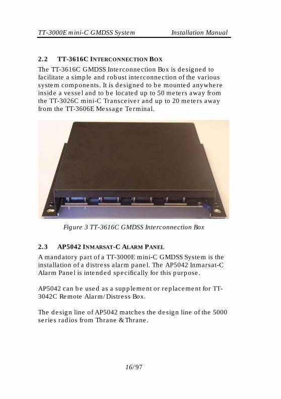
2.2 TT-3616C INTERCONNECTION BOX
The TT-3616C GMDSS Interconnection Box is designed to facilitate a simple and robust interconnection of the various system components. It is designed to be mounted anywhere inside a vessel and to be located up to 50 meters away from the TT-3026C mini-C Transceiver and up to 20 meters away from the TT-3606E Message Terminal.
Figure 3 TT-3616C GMDSS Interconnection Box
2.3 AP5042 INMARSAT-C ALARM PANEL
A mandatory part of a TT-3000E mini-C GMDSS System is the installation of a distress alarm panel. The AP5042 Inmarsat-C Alarm Panel is intended specifically for this purpose. AP5042 can be used as a supplement or replacement for TT-3042C Remote Alarm/Distress Box. The design line of AP5042 matches the design line of the 5000 series radios from Thrane & Thrane.
16/97

TT-3000E mini-C GMDSS System Installation Manual
Figure 4 AP5042 Inmarsat-C Alarm Panel
Up to four AP5042 Inmarsat-C Alarm Panels can be connected to a TT-3000E mini-C GMDSS System.
2.4 TT-3042C REMOTE ALARM/DISTRESS BOX
A mandatory part of a TT-3000E mini-C GMDSS System is the installation of a distress alarm panel. The TT-3042C Remote Alarm/Distress Box is designed specifically for this purpose.
17/97
TT-3000E mini-C GMDSS System Installation Manual
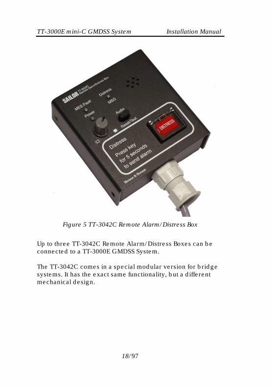
Figure 5 TT-3042C Remote Alarm/Distress Box
Up to three TT-3042C Remote Alarm/Distress Boxes can be connected to a TT-3000E GMDSS System. The TT-3042C comes in a special modular version for bridge systems. It has the exact same functionality, but a different mechanical design.
18/97
TT-3000E mini-C GMDSS System Installation Manual
2.5 AP5065 ALARM PANEL
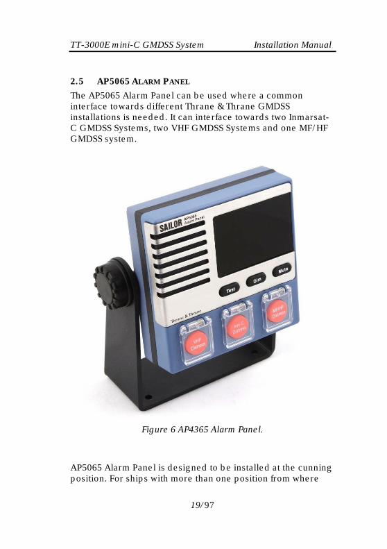
The AP5065 Alarm Panel can be used where a common interface towards different Thrane & Thrane GMDSS installations is needed. It can interface towards two Inmarsat-C GMDSS Systems, two VHF GMDSS Systems and one MF/HF GMDSS system.
Figure 6 AP4365 Alarm Panel.
AP5065 Alarm Panel is designed to be installed at the cunning position. For ships with more than one position from where
19/97

TT-3000E mini-C GMDSS System Installation Manual the ship is normally navigated, it’s possible to interconnect up to three AP5065 Alarm Panels. The AP5065 Alarm Panel has an interface towards 3rd party monitoring systems. The relevant alarm statuses for all attached GMDSS systems are constantly transmitted on a RS422 line. On another RS422 line it is possible for 3rd party equipment to issue a mute command in order to silence all GMDSS systems. For installation of AP5065, please refer to the installation manual delivered with the unit.
20/97
TT-3000E mini-C GMDSS System Installation Manual
2.6 TT-3606E MESSAGE TERMINAL
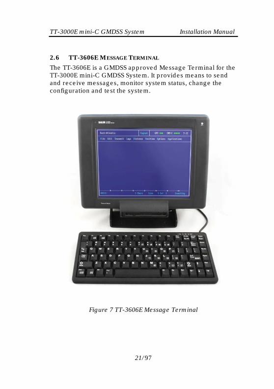
The TT-3606E is a GMDSS approved Message Terminal for the TT-3000E mini-C GMDSS System. It provides means to send and receive messages, monitor system status, change the configuration and test the system.
Figure 7 TT-3606E Message Terminal
21/97

TT-3000E mini-C GMDSS System Installation Manual
2.7 TT-3608A HARD COPY PRINTER
Figure 8 TT-3608A Hard Copy Printer
The physical installation of the printer is covered by this manual, section 4.6. Usage and maintenance of the printer is covered by the manual provided with the printer.
22/97

TT-3000E mini-C GMDSS System Installation Manual
2.8 N163S POWER SUPPLY
The N163S is an AC/DC power supply designed to automatically switch from mains to battery supply in case of mains dropout.
Figure 9 N163S Power Supply
Use of the N163S is optional, but it is a requirement of IMO that the GMDSS installation is made such that it is operational both from the ships main source of energy and from an alternative source of energy. Please refer to the installation manual delivered with N163S for further installation information.
23/97
TT-3000E mini-C GMDSS System Installation Manual 2.9 TT-3606E OPT. 003 NMEA ADAPTER
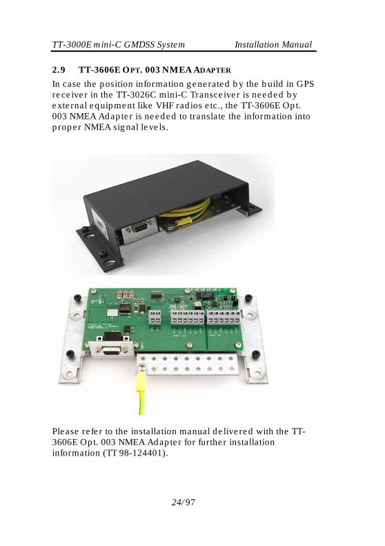
In case the position information generated by the build in GPS receiver in the TT-3026C mini-C Transceiver is needed by external equipment like VHF radios etc., the TT-3606E Opt. 003 NMEA Adapter is needed to translate the information into proper NMEA signal levels.
Please refer to the installation manual delivered with the TT-3606E Opt. 003 NMEA Adapter for further installation information (TT 98-124401).
24/97
TT-3000E mini-C GMDSS System Installation Manual
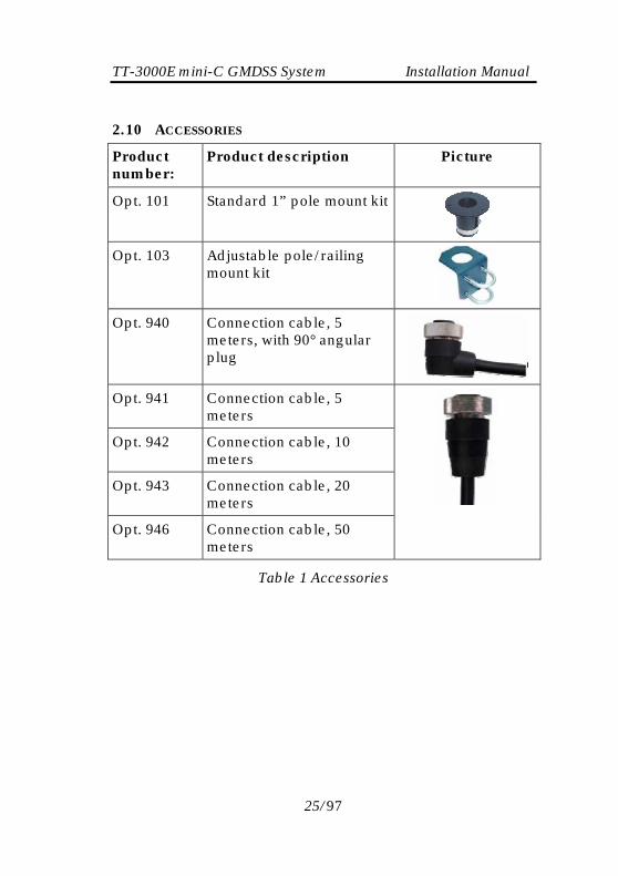
2.10 ACCESSORIES
Product number:
Product description Picture
Opt. 101 Standard 1” pole mount kit
Opt. 103 Adjustable pole/railing mount kit
Opt. 940 Connection cable, 5 meters, with 90° angular plug
Opt. 941 Connection cable, 5 meters
Opt. 942 Connection cable, 10 meters
Opt. 943 Connection cable, 20 meters
Opt. 946 Connection cable, 50 meters
Table 1 Accessories
25/97

TT-3000E mini-C GMDSS System Installation Manual
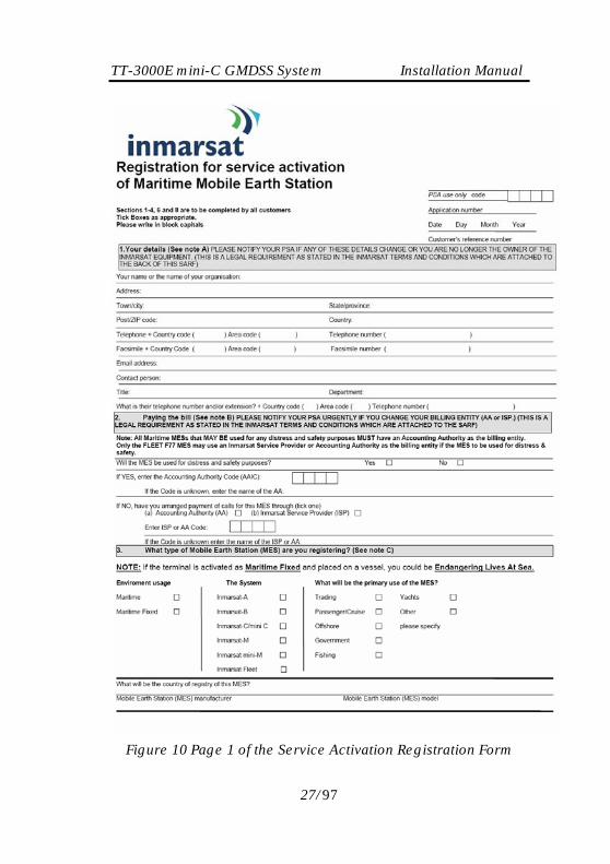
3 REGISTRATION Before use of the TT-3026C mini-C transceiver on the Inmarsat-C system it must be registered to the system, which involves a little paper work. This is done using the SARF (Service Activation Registration Form) supplied with the mini-C MES. Page 1 of the SARF is shown in Figure 6. The SARF for registration of Maritime MES can also be found on www.inmarsat.org (CUSTOMER SUPPORT -> SERVICE ACTIVATION). The site also contains notes on how to complete the maritime form. The Service Activation Registration Form contains different abbreviations that will be explained here. The mini-C MES must be registered at either a PSA company or directly to the ISP. A PSA is a company handling the activation of Inmarsat mobiles and is short for Point of Service Activation. ISP is the company that provides the Inmarsat service and is short for Inmarsat Service Provider. In many cases the PSA and ISP is the same company that also operates a Land Earth Station (LES). The local PSA or ISP can be obtained by following the guidelines in the registration form. The Service Activation Registration Form also includes information needed to find out how to pay the bill for the Inmarsat-C service. This payment will be done directly to the Accounting Authority. In many cases the Accounting Authority (AA) is also the same company as the Inmarsat Service Provider (ISP). In addition to the general information like name, address, etc. the ISN of the mini-C MES must be specified. The ISN is located on the Delivery Note and in the bottom of the mini-C MES. Refer to Table 1 for answers to selected SARF questions.
26/97
TT-3000E mini-C GMDSS System Installation Manual
Figure 10 Page 1 of the Service Activation Registration Form
27/97

TT-3000E mini-C GMDSS System Installation Manual
Question in SARF Answer Will the MES be used for distress and safety purposes?
Yes
The System?
Inmarsat-C/mini C
Mobile Earth Station (MES) manufacturer Thrane & Thrane A/S Mobile Earth Station (MES) model
TT-3026C
Table 2 Answers to selected questions in SARF
When the mini-C MES is registered at the ISP it is ready to be used on the Inmarsat-C network. The ISP has returned a Mobile Number for the mini-C MES and prior to operating the mini-C MES it must be configured with this Mobile Number. The mobile number can be entered using the TT-3606E Message Terminal:
1. Choose Options, Configuration, Terminal mode (Alt, O, C, T) and wait for the blinking cursor to appear. This may take a while if the transceiver and the Message Handling program are communicating.
2. Press Enter to see the prompt ' :' on the screen.
3. Type se -u xxxxxxxxx <enter>, where xxxxxxxxx is the mobile number.
4. Press Esc to leave the Terminal Mode when you're done to ensure the functionality of your system.
For further information on the terminal interface please refer to the Software Interface Reference Manual [2].
28/97

TT-3000E mini-C GMDSS System Installation Manual
4 SYSTEM INSTALLATION This chapter provides specific information enabling you to install the TT-3000E mini-C GMDSS System with a minimal effort. The default, or factory configuration, is described together with procedures for altering this configuration. The GMDSS system components covered in this section are: TT-3026C Mini-C Transceiver TT-3616C GMDSS Interconnection Box TT-3606E Message Terminal TT-3601E Keyboard TT-3608A Hard Copy Printer TT-3042C Remote Alarm/Distress Box AP5042 Inmarsat-C Alarm Panel Please note that installation of N163S Power Supply and AP5065 Alarm Panel are covered by separate manuals provided with the units. IMPORTANT: DO NEVER TEST THIS INSTLLATION BY SENDING AN ALERT ON-AIR. ALSO BE CAREFUL NOT TO SEND FALSE ALERTS DURING INSTALLATION. Any distress alerts coming through the Inmarsat-C network will be taken seriously by the receiving authorities. If a false alert is sent by accident – despite all precautions – it is important to inform the relevant authorities before a rescue operation is initiated. See the User’s Manual for more information about this [1].
29/97

TT-3000E mini-C GMDSS System Installation Manual 4.1 POWER REQUIREMENTS
A TT-3000E mini-C GMDSS System operates on either 115 VAC, 230 VAC or a 24 V floating DC (nominal value)1. The N163S provides automatic switch over to the DC supply in case a drop out occurs on the mains. The total power consumption varies primarily due to system activities. As a guide-line, please note the power consumption of the following equipment:
Power requirements Receive mode
Transmit mode
TT-3026C mini-C Transceiver. Floating DC (10.5-32V).
1.8W Max. 32W
TT-3616C GMDSS Interconnection Box. Floating DC (10.5-32V).
1W 2W
TT-3606E Message Terminal, incl. Keyboard. Floating DC (10.5 - 32V)
13W average
20W peak
TT-3608A Printer 220AC or option 010 DC supply floating (10.5 - 32V)
33W 33W
AP5042 (8 - 32V) 0.3W 0.8W AP5065 (21 - 32V) 1W 3W TT-3042C Remote Alarm/Distress Box 0.2 W
standby 1W
Total: 50W 92W
Table 3 System component power requirements
4.1.1 FUSES
In case you experience that a fuse needs replacement, please check that the equipment has not been exposed to physical damage before fuse replacement takes place. As a guide-line, please note the equipment fuse location given in Table 4.
1 The system can be operated from a DC supply down to 12V provided the cable lengths are limited, please refer to section 4.4.3.
30/97

TT-3000E mini-C GMDSS System Installation Manual
Equipment Location Fuse size
TT-3026C mini-C
Transceiver
Internal self reset able
poly fuse
NA
TT-3606E Message
Terminal
Internal self reset able
poly fuse
NA
TT-3042C Remote
Alarm/Distress box
No fuse NA
AP5042 Inmarsat-C
Alarm Panel
Internal self reset able
poly fuse
NA
AP5065 Alarm Panel Internal self reset able
poly fuse
NA
TT-3606E Opt. 003
NMEA Adapter
Internal self reset able
poly fuse
NA
TT-3616C GMDSS
Interconnection Box
Internally accessed,
remove top cover
5 A ATO® type
(As used in cars)
TT-3608A Hard Copy
Printer
Internally accessed,
remove top cover
1.5A mT.
N163S Power Supply
- Mains supply
Externally accessed. 1 A mT (230VAC)
2 A mT (110VAC)
N163S Power Supply
- Battery input
Internally accessed,
remove top cover
10 A ATO® type
(As used in cars)
Table 4 TT-3000E mini-C GMDSS System Fuses
The fuse located in the TT-3616C GMDSS Interconnection Box serves as fuse for the TT-3616C internal supply as well as fuse for the power delivered to the TT-3026C mini-C Transceiver, hence the high value of 5A.
31/97
TT-3000E mini-C GMDSS System Installation Manual
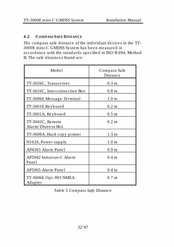
4.2 COMPASS SAFE DISTANCE
The compass safe distance of the individual devices in the TT-3000E mini-C GMDSS System has been measured in accordance with the standards specified in ISO/R 694, Method B. The safe distances found are:
Model Compass Safe Distance
TT-3026C, Transceiver 0.3 m
TT-3616C, Interconnection Box 0.8 m
TT-3606E Message Terminal 1.0 m
TT-3601E Keyboard 0.2 m
TT-3601A, Keyboard 0.5 m
TT-3042C, Remote Alarm/Distress Box
0.2 m
TT-3608A, Hard copy printer 1.3 m
N163S, Power supply 1.0 m
AP4365 Alarm Panel 0.9 m
AP5042 Inmarsat-C Alarm Panel
0.4 m
AP5065 Alarm Panel 0.4 m
TT-3606E Opt. 003 NMEA Adapter
0.7 m
Table 5 Compass Safe Distance
32/97

TT-3000E mini-C GMDSS System Installation Manual
4.3 TT-3026C MINI-C TRANSCEIVER INSTALLATION
The TT-3026C mini-C Transceiver is equipped with an 18-pin female connector and is meant for flat surface mounting or pole mounting using an optional adaptor.
4.3.1 MOUNTING OPTIONS
This section describes the different mounting options applicable for the TT-3026C mini-C transceiver.
4.3.1.1 DRILLED HOLES ON A FLAT SURFACE
1) Drill the 4 holes (3 for the mounting screws, 1 for cable access) using the mounting stencil in Appendix A.
2) Place the friction gasket on the surface. 3) Connect the cable and mount the screws.
4.3.1.2 POLE MOUNT 1”
40-3026 Opt. 101 is a standard 1” pole mount, Illustrated in Figure 11.
1) Pull the cable in the pole and adapter. 2) Connect the cable to the transceiver. 3) Mount the adapter on the transceiver using screws. 4) Tighten the adapter to the pole. Adjustable between
20 - 35 millimetre NOTE: THE POLE MOUNT DEVICE HAS TO BE DISMOUNTED FROM THE TRANSCEIVER BEFORE THE CABLE IS CONNECTED OR DISCONNECTED.
33/97

TT-3000E mini-C GMDSS System Installation Manual
Figure 11 1" Pole mounting
Important note: When mounting the mini-C transceiver in very harsh environments i.e. directly exposed to exhaust fumes, it is recommended that the Adjustable Pole/Railing Mount described below is used!
4.3.1.3 ADJUSTABLE POLE/RAILING MOUNT
403026 Opt. 103 is an adjustable pole/railing mount shown in Figure 12.
1) Attach the pole mount to the transceiver using the 3 screws.
2) Mount the device to the pole in one of the 2 directions. 3) Connect the cable.
Figure 12 Vertical and Horizontal adjustable pole mount
34/97
TT-3000E mini-C GMDSS System Installation Manual
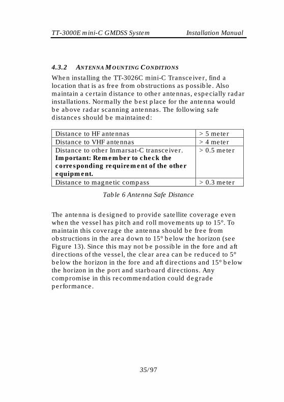
4.3.2 ANTENNA MOUNTING CONDITIONS
When installing the TT-3026C mini-C Transceiver, find a location that is as free from obstructions as possible. Also maintain a certain distance to other antennas, especially radar installations. Normally the best place for the antenna would be above radar scanning antennas. The following safe distances should be maintained:
Distance to HF antennas > 5 meter Distance to VHF antennas > 4 meter Distance to other Inmarsat-C transceiver. Important: Remember to check the corresponding requirement of the other equipment.
> 0.5 meter
Distance to magnetic compass > 0.3 meter
Table 6 Antenna Safe Distance
The antenna is designed to provide satellite coverage even when the vessel has pitch and roll movements up to 15°. To maintain this coverage the antenna should be free from obstructions in the area down to 15° below the horizon (see Figure 13). Since this may not be possible in the fore and aft directions of the vessel, the clear area can be reduced to 5° below the horizon in the fore and aft directions and 15° below the horizon in the port and starboard directions. Any compromise in this recommendation could degrade performance.
35/97

TT-3000E mini-C GMDSS System Installation Manual
15
Horizon
15
Horizon
Zenith
Obstructions should be below these lines
oo
Figure 13 Viewing Angle to the Horizon
If an obstruction such as a pole or a funnel is unavoidable, the Transceiver must be positioned in such a location that the obstruction covers no more than a 2° arc along the horizon. To calculate the minimum distance, use the following formula: Safe distance = 29 * Diameter of obstruction Example:
Obstruction is a 4" pole (Diameter = 0.1 m) Safe distance is 29 * 0.1 m = 2.9 m
2.9m apart to ensure that obstruction covers no greater than 2° arc
TT-3026C mini-C Transceiver4" diameter
obstruction
Figure 14 Mounting near pole or funnel (overhead view)
36/97

TT-3000E mini-C GMDSS System Installation Manual 4.3.3 SAFETY DISTANCE FOR ANTENNA UNITS
When transmitting, the electromagnetic field radiated from the antenna can be harmful. To avoid danger, keep a distance of 1 ft. (30 cm.) from the transceiver. To be sure that this distance is respected, the TT-3026C mini-C Transceiver is provided with a label declaring a minimum safety distance of 1 ft. (30 cm.) on the antenna. The relation between the power intensity and distance is as follows:
Distance (m) from antenna Radiated intensity (W/m2) 0.20 10 0.13 25 0.07 100
Table 7 Radiated intensity
4.3.4 WIRING THE TT-3026C MINI-C TRANSCEIVER
The TT-3026C must be connected to the TT-3616C GMDSS Interconnection Box by use of a special cable delivered with the system. There are 4 lengths of connecting cables available from T&T: 5m, 10m, 20m and 50m (refer to section 2.10 for option numbers). Refer to Appendix B to get information about the individual signals found in the cable.
4.3.5 GROUNDING
Make sure that the shield of the cable is connected to a proper ground, i.e. the ship’s structure / hull via the cable relief bracket found in the TT-3616C GMDSS Interconnection Box. This is very important in order to safely bypass interference from Radar, VHF/MF/HF radio equipment and other environmental noise sources (see Figure 23and Figure 24).
4.3.6 POWER CONNECTION
The power connections of the TT-3026C consist of 4 wires (two red and two black). All 4 wires MUST be used (see Figure 25).
37/97

TT-3000E mini-C GMDSS System Installation Manual The power connection input is floating (i.e., there is no galvanic connection from DC+ and DC- to the connector housing = GND = cable shield).
4.3.7 POWER REQUIREMENTS
The TT-3026C mini-C transceiver is designed to operate on floating DC in the nominal range 12V to 24V, which makes an AC/DC converter needed, in case the system is to work in an AC environment. In case an AC/DC converter is used, please make sure to leave the output of the AC/DC converter floating, i.e. do NOT connect the negative wire to ships structure. The transceiver has an actual working voltage range of 10.5V to 32V to accommodate power supply variations outside the nominal range. Note: In case a 50 meter transceiver cable is used (Opt. 946), the minimum supply voltage measured at the TT-3616C terminals must be 16VDC.
4.3.8 GENERAL PURPOSE I/O PORTS
The TT-3026C mini-C Transceiver also contain two configurable input/output ports available to the user via the TT-3616C GMDSS Interconnection Box. They are named I/O 5 and I/O6. When used as outputs, the ports have the following characteristics:
• Open collector output. • Internal 2.2kOhm pull-up resistor to 3.3VDC. • Voltage allowed between GND and the output pin is
0V to 5V. • Maximum current into the I/O pin is 25mA.
When used as inputs, the ports have the following characteristics:
• Internal 2.2kOhm pull-up resistor to 3.3VDC. • To guarantee a logic low input signal, the input
voltage must be < 0.5V.
38/97

TT-3000E mini-C GMDSS System Installation Manual
• To guarantee a logic high input signal, the input voltage must be >3V.
• Voltage allowed between GND and the input pin is 0V to 5V.
WARNING: When using the I/O ports, it is important not to apply voltages between GND and the I/O pin higher than 5 VDC as this can cause damage to the transceiver. Negative voltages are not allowed either.
39/97

TT-3000E mini-C GMDSS System Installation Manual 4.4 TT-3616C GMDSS INTERCONNECTION BOX
The TT-3616C GMDSS Interconnection Box is designed to facilitate a simple and robust interconnection of the various system components.
Figure 15 Outside view of TT-3616C
Figure 16 Inside view of TT-3616C
40/97

TT-3000E mini-C GMDSS System Installation Manual 4.4.1 MOUNTING OF TT-3616C
The TT-3616C is designed to be mounted on a flat surface anywhere inside a vessel and to be located up to 50 meters away from the TT-3026C mini-C Transceiver and up to 20 meters away from the TT-3606E Message Terminal. In order to ease the installation, please observe the minimum clearing area as given in Figure 17.
Figure 17 Recommended free space around TT-3616C.
41/97
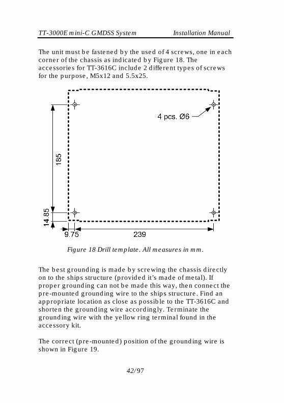
TT-3000E mini-C GMDSS System Installation Manual The unit must be fastened by the used of 4 screws, one in each corner of the chassis as indicated by Figure 18. The accessories for TT-3616C include 2 different types of screws for the purpose, M5x12 and 5.5x25.
Figure 18 Drill template. All measures in mm.
The best grounding is made by screwing the chassis directly on to the ships structure (provided it’s made of metal). If proper grounding can not be made this way, then connect the pre-mounted grounding wire to the ships structure. Find an appropriate location as close as possible to the TT-3616C and shorten the grounding wire accordingly. Terminate the grounding wire with the yellow ring terminal found in the accessory kit. The correct (pre-mounted) position of the grounding wire is shown in Figure 19.
42/97

TT-3000E mini-C GMDSS System Installation Manual
Figure 19 Grounding using 4mm2 wire.
Please note the use of a washer as shown in Figure 19. The grounding wire delivered with the TT-3616C has a length of 1 meter and a wire cross section of 4mm2. Avoid extending the length of the grounding wire, as the protective effect will be severely degraded in such a case.
43/97

TT-3000E mini-C GMDSS System Installation Manual
4.4.2 HANDLING OF WIRE TERMINALS IN TT-3616C
To help inserting wires into the terminals, a special tool is delivered as part of the accessory kit. It is used as shown in Figure 20.
Please be careful not to apply to much pressure, as this might damage the top of
the terminal housing. In case the special tool is lost, a small screwdriver can be used as well.
4.4.3 CONNECTING POWER TO TT-3616
The power connector is designed to accsection area up to 2.5mm2. The requireddepends on the actual supply voltage, thand the transceiver cable length. Typicagiven in Table 8. Cross section [mm2] 0.5 1Resistance [Ω/km] 32.2 16.1
Table 8 Typical cable resistance
To calculate the maximum wire length incable type and transceiver cable lengthformulas can be used:
CABLE
MINMMAX R
VL )5.10(15620,−
⋅= and MAXL
44/97
Figure 20 Wire tool.
C
ept wire with a cross wire cross section e supply cable length l cable resistance is
1.5 2 2.510.7 8.05 6.76
meters for a given , the following
CABLE
MINM R
V )16(15650,−
⋅=

TT-3000E mini-C GMDSS System Installation Manual , where VMIN is the minimum guaranteed power supply voltage and RCABLE is the cable resistance in Ω/km. Example 1:
Using the N163S with a 24V battery backup, VMIN can be assumed to be above 22V. Using 50 meter of transceiver cable and a wire cross section of 1mm2, the maximum power supply cable length is: LMAX,50M = 58 m.
Example 2:
Using a 12V battery for backup, VMIN can be assumed to be above 11V (if properly charged). Using 20 meter of transceiver cable and a wire cross section of 2.5mm2, the maximum power supply cable length is: LMAX, 20M=11 m.
When connecting the cable to TT-3616C, make sure the cable screen is properly terminated at the cable relief bracket as shown in Figure 21. Connect the positive supply wire to the terminal denoted DC+ and the negative supply wire to the terminal denoted DC-.
Figure 21 Power cable connections.
45/97
TT-3000E mini-C GMDSS System Installation Manual The “Remote On/Off” terminal located next to DC- must be connected to DC- in order to turn on the unit. By combining this “Remote On/Off” with the similar signal on the TT-3606E Message Terminal and making the connection to DC- via a switch, then all equipment except the printer can be switch on and off by a simple low power switch.
4.4.4 CONNECTING TT-3026C TO TT-3616C
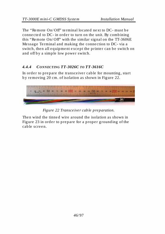
In order to prepare the transceiver cable for mounting, start by removing 20 cm. of isolation as shown in Figure 22.
Figure 22 Transceiver cable preparation.
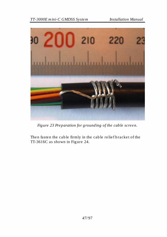
Then wind the tinned wire around the isolation as shown in Figure 23 in order to prepare for a proper grounding of the cable screen.
46/97
TT-3000E mini-C GMDSS System Installation Manual
Figure 23 Preparation for grounding of the cable screen.
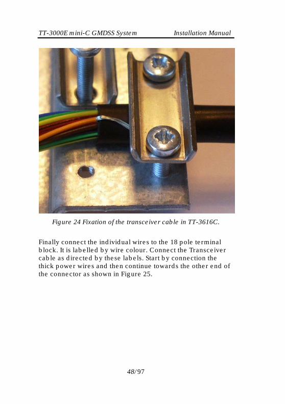
Then fasten the cable firmly in the cable relief bracket of the TT-3616C as shown in Figure 24.
47/97
TT-3000E mini-C GMDSS System Installation Manual
Figure 24 Fixation of the transceiver cable in TT-3616C.
Finally connect the individual wires to the 18 pole terminal block. It is labelled by wire colour. Connect the Transceiver cable as directed by these labels. Start by connection the thick power wires and then continue towards the other end of the connector as shown in Figure 25.
48/97

TT-3000E mini-C GMDSS System Installation Manual
Figure 25 Mounting of transceiver cable wires.
49/97

TT-3000E mini-C GMDSS System Installation Manual
4.4.5 CONNECTING TT-3606E TO TT-3616C
Mount the RS232 cable supplied with the TT-3606E Message Terminal as shown in Figure 26.
Figure 26 RS232 cable connection.
Be aware, that it might be easier to tighten the screw locks on the RS232 cable, if it’s mounted before the adjoining cables are mounted. In order not to stress the connector, the cable release bracket shown in Figure 26 must be used. An extended serial communication cable must not exceed 20 meters.
50/97
TT-3000E mini-C GMDSS System Installation Manual
4.4.6 CONNECTING TT-3042C TO TT-3616C
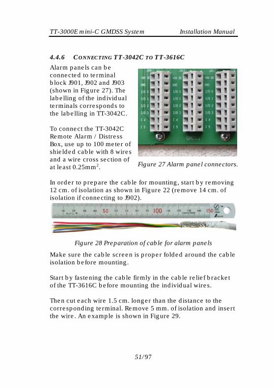
Alarm panels can be connected to terminal block J901, J902 and J903 (shown in Figure 27). The labelling of the individual terminals corresponds to the labelling in TT-3042C. To connect the TT-3042C Remote Alarm / Distress Box, use up to 100 meter of shielded cable with 8 wires and a wire cross section of at least 0.25mm2.
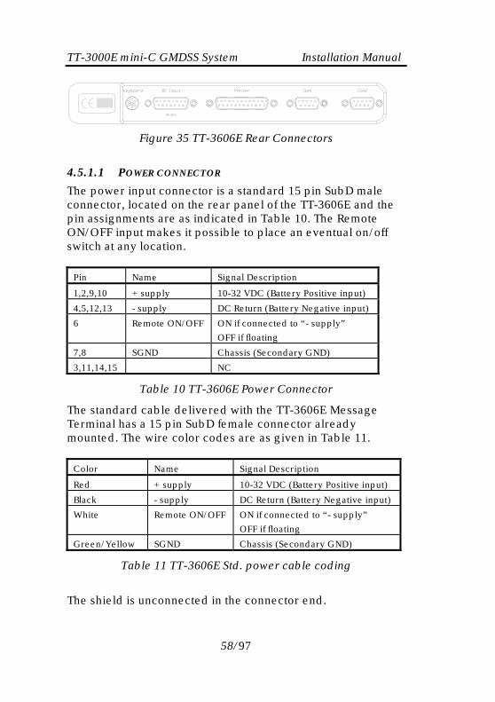
In order to prepare the cable 12 cm. of isolation as shown inisolation if connecting to J902)
Figure 28 Preparation
Make sure the cable screen isisolation before mounting. Start by fastening the cable firof the TT-3616C before mount Then cut each wire 1.5 cm. loncorresponding terminal. Remthe wire. An example is shown
5
Figure 27 Alarm panel connectors.
for mounting, start by removing Figure 22 (remove 14 cm. of .
of cable for alarm panels
proper folded around the cable
mly in the cable relief bracket ing the individual wires.
ger than the distance to the ove 5 mm. of isolation and insert
in Figure 29.
1/97

TT-3000E mini-C GMDSS System Installation Manual
Figure 29 Mounting of cables for alarm panels
To avoid installation errors please write the match between wire colour codes and connector labels in Table 9 and check that this is coherent with the wiring of the TT-3042C Remote Alarm/Distress Box (ref. section 4.7). Label Wire colour code +9V DC GND I/O 0 I/O 1 I/O 2 I/O 3 I4 I5
Table 9 Actual wire colour codes
4.4.7 CONNECTING AP50XX TO TT-3616C
Up to four AP5042 and one AP50652 can be connected directly to the TT-3616C3 via the RS485 interface accessible on connector J302.
2 More AP5065 can be connected in parallel, refer to the AP5065 Installation Manual for more information. 3 The TT-3616C must be rev. B or newer, refer to the label on the side of the top cover.
52/97

TT-3000E mini-C GMDSS System Installation Manual
Figure 30 Location of connector J302
The cable used should be shielded twisted pair 2x2x0.2mm2 or better (AWG 24 is 0.205mm2), installed as one string and terminated in both ends. The total length of the cable from termination to termination should not exceed 500 meters and the length from TT-3616C to either end of the cable should not exceed 250 meter. The cable screen should only be connected at the TT-3616C. Please note, that J302 only accepts wires with a cross section of up to 0.5mm2.
4.4.7.1 T-PORT WIRING
The individual units can be connected to the string using short stubs with a maximum length of 5m as shown in Figure 31.
Figure 31 Alarm panels on RS485 bus – T-Port wiring.
53/97

TT-3000E mini-C GMDSS System Installation Manual A setup as shown in Figure 31 can be made using commercially available DeviceNet® cable components. For more information on this solution please refer to Appendix D.
4.4.7.2 DIRECT WIRING
Another kind of wiring is the one shown in Figure 32. There are two pins for each signal in the DSUB9 connectors, thus soldering of each wire in the cable can be performed in a robust manner, provided the cable is not too thick.
98
7
6
54
3
21
98
7
6
54
3
21
Data -
Data +
+9V
GND98
7
6
54
3
21
Data -
Data +
+9V
GND
Male DSUB9
Male DSUB9
Male DSUB9
TT-3616C
98
7
6
54
3
21
Male DSUB9
Connect to AP50xx
98
7
6
54
3
21
Data -
Data +
+9V
GND
Male DSUB9
GND
Data-
Data+
+9V
J302
Strap activates internal termination
resistor
Shield
Shield
Connect to AP50xx
Connect to AP50xx
Connect to AP50xx
Connect to AP50xx
The following pins are internally connected in AP50XX: 1-2, 3-7, 4-5 & 8-9. Pin 6 are internally connected to pin 5 via a termination resistor of 120 Ω -150 Ω.
Figure 32 Alarm panels on RS485 bus – direct wiring
54/97

TT-3000E mini-C GMDSS System Installation Manual Make sure the cable shield is firmly connected to TT-3616C using the cable relief brackets. Make sure, that the twisted pairs are actually twisted all the way to the terminal strip. If the cable is terminated in TT-3616C, please mount a 120Ω 1/4W resistor between Data+ and Data- in order to ensure a proper termination of the signal.
4.4.7.3 DIRECT WIRING - AP5042 POWERED FROM TT-3616C
In case one of the AP5042’s are located less than 50 meters from the interconnection box, a setup as shown in Figure 33 can be used in order to save an extra power supply unit.
Figure 33 Powering AP5042 directly from TT-3616C
55/97

TT-3000E mini-C GMDSS System Installation Manual The TT-3616C is capable of sourcing power for two AP5042 Inmarsat-C Alarm Panels, thus it is possible to add a second AP5042 sourced directly from the TT-3616C, provided: • It is connected to TT-3616C using a wire length of less
than 5 meters. • The wire is NOT terminated at the AP5042. • No TT-3042C is connected at J903 and +9V and GND for
the extra alarm panel is taken from J903. It might be necessary to join the three Data+ signals as well as the three Data- signals externally (within centimeters from J302) as the resulting wire cross section might be too thick for J302.
56/97

TT-3000E mini-C GMDSS System Installation Manual
4.5 TT-3606E MESSAGE TERMINAL
The TT-3606E is a GMDSS approved Message Terminal for the TT-3000E mini-C GMDSS System.
Figure 34 TT-3606E Message Terminal.
In the following sections the interface to the 3606E Message Terminal is described. Please be advised that a special Reference Manual for the TT-3606E Message Terminal is available [4].
4.5.1 CONNECTORS
An illustration of the rear connectors are shown in Figure 35.
57/97
TT-3000E mini-C GMDSS System Installation Manual
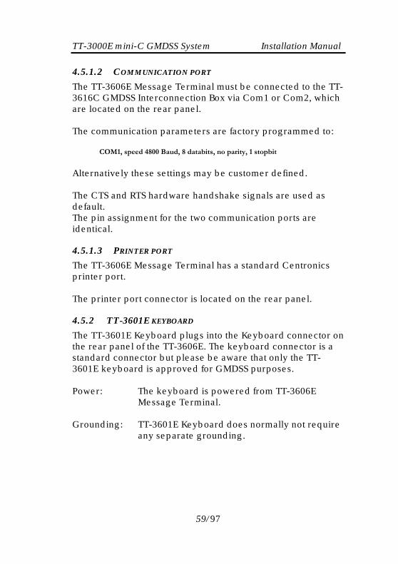
Figure 35 TT-3606E Rear Connectors
4.5.1.1 POWER CONNECTOR
The power input connector is a standard 15 pin SubD male connector, located on the rear panel of the TT-3606E and the pin assignments are as indicated in Table 10. The Remote ON/OFF input makes it possible to place an eventual on/off switch at any location.
Pin Name Signal Description
1,2,9,10 + supply 10-32 VDC (Battery Positive input)
4,5,12,13 - supply DC Return (Battery Negative input)
6 Remote ON/OFF ON if connected to “- supply”
OFF if floating
7,8 SGND Chassis (Secondary GND)
3,11,14,15 NC
Table 10 TT-3606E Power Connector
The standard cable delivered with the TT-3606E Message Terminal has a 15 pin SubD female connector already mounted. The wire color codes are as given in Table 11.
Color Name Signal Description
Red + supply 10-32 VDC (Battery Positive input)
Black - supply DC Return (Battery Negative input)
White Remote ON/OFF ON if connected to “- supply”
OFF if floating
Green/Yellow SGND Chassis (Secondary GND)
Table 11 TT-3606E Std. power cable coding
The shield is unconnected in the connector end.
58/97
TT-3000E mini-C GMDSS System Installation Manual 4.5.1.2 COMMUNICATION PORT
The TT-3606E Message Terminal must be connected to the TT-3616C GMDSS Interconnection Box via Com1 or Com2, which are located on the rear panel. The communication parameters are factory programmed to: COM1, speed 4800 Baud, 8 databits, no parity, 1 stopbit Alternatively these settings may be customer defined. The CTS and RTS hardware handshake signals are used as default. The pin assignment for the two communication ports are identical.
4.5.1.3 PRINTER PORT
The TT-3606E Message Terminal has a standard Centronics printer port. The printer port connector is located on the rear panel.
4.5.2 TT-3601E KEYBOARD
The TT-3601E Keyboard plugs into the Keyboard connector on the rear panel of the TT-3606E. The keyboard connector is a standard connector but please be aware that only the TT-3601E keyboard is approved for GMDSS purposes. Power: The keyboard is powered from TT-3606E
Message Terminal.
Grounding: TT-3601E Keyboard does normally not require any separate grounding.
59/97

TT-3000E mini-C GMDSS System Installation Manual
4.5.3 MOUNTING
Figure 36 illustrates the dimension of the panel cut-out and position of mounting holes when mounting the TT-3606E Message Terminal in a console.
Figure 36 Mounting holes for TT-3606E
Figure 37 illustrates the position of the mounting holes for the mounting bracket.
60/97

TT-3000E mini-C GMDSS System Installation Manual
Figure 37 TT-3606E Mounting Bracket
61/97

TT-3000E mini-C GMDSS System Installation Manual
4.6 TT-3608A HARD COPY PRINTER
Figure 38 TT-3608A Hard copy printer
The TT-3608A Hard Copy Printer must be connected to the TT-3606E Message Terminal in order to print SafetyNet EGC’s with Distress priority automatically. The Integrated Capsat System is designed to allow the operator to guide incoming messages to the TT-3608A Hard Copy Printer and/or the TT-3606E Message Terminal for floppy disk storage. In case TT-3608A and TT-3606E are turned off, the Transceiver will hold the incoming messages in the internal memory for at approximately 48 hours for later Hard Coping. The enclosed standard cable allows the printer to be located up to 1.5 meters from the Transceiver. A special low impedance cable is available for printer locations up to 20 meters from the Message Terminal. The TT-3608A Hard Copy Printer is supplied with a mounting frame, offering horizontally oriented secured mounting. The printer connector is located on the rear panel. The interface conforms to a standard Centronics type interface.
62/97

TT-3000E mini-C GMDSS System Installation Manual 4.6.1 MOUNTING PLATE
A mounting plate is supplied with the TT-3608A Hard Copy Printer, for horizontally oriented secured mounting see section 4.6.3.
4.6.2 ROLL PAPER STAND
Figure 39 TT-3608A Paper Roll Stand
A roll paper stand is available for the TT-3608A Hard Copy Printer. This enables the printer to signal an advanced warning of a paper low condition, when the paper roll is almost empty. The printer continues to work, and "Printer almost out of paper" message is displayed by the message terminal. When a "Printer almost out of paper" condition occur the audio alarm will sound and the fault indication on any connected alarm panel will be switched on - these indications continues until the paper roll is replaced. If the printer is set off-line using the "select" button or powered off using the power switch, the audio alarm and the fault indication in the alarm panels will be switched on. The DIP switch 8 “ROLL PAPER STAND” in the printer, must be set to OFF, which selects roll paper stand, and the roll paper stand connector must be attached to the back of the printer
63/97

TT-3000E mini-C GMDSS System Installation Manual before the advanced paper low option is enabled. The DIP switch can be accessed by removing the switch cover from the back of the printer.
4.6.3 MOUNTING
Figure 40 Mounting holes for TT-3608A (Unit is mm)
64/97

TT-3000E mini-C GMDSS System Installation Manual
4.7 AP5042 INMARSAT-C ALARM PANEL
Figure 41 AP5042 Inmarsat-C Alarm Panel
From the AP5042 Inmarsat-C Alarm Panel distress alerts can be initiated. A distress alert can be initiated by pressing the Distress button for five seconds. The AP5042 also has an indicator for reception of EGC messages with distress or urgent priority.
4.7.1 MOUNTING
Two mounting options exist: • Bracket • Flush mount
65/97

TT-3000E mini-C GMDSS System Installation Manual 4.7.1.1 BRACKET MOUNT
The outline and dimensions for a bracket mounted AP5042 are shown in Figure 42.
100
128
min. 150 60.5
31.5
Space for cable entry
All dimensions are in millimetres
Figure 42 Outline & dimensions - bracket mount
66/97

TT-3000E mini-C GMDSS System Installation Manual The drilling template for the bracket is shown in Figure 43.
Figure 43 Drilling template - bracket
67/97
TT-3000E mini-C GMDSS System Installation Manual
4.7.1.2 FLUSH MOUNT
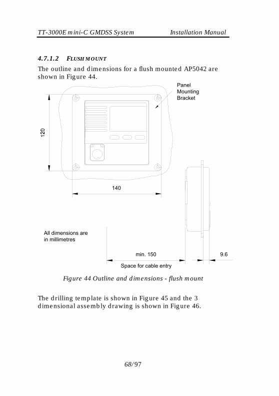
The outline and dimensions for a flush mounted AP5042 are shown in Figure 44.
Panel Mounting Bracket
Space for cable entry
min. 150 9.6
140
All dimensions are in millimetres
Figure 44 Outline and dimensions - flush mount
The drilling template is shown in Figure 45 and the 3 dimensional assembly drawing is shown in Figure 46.
68/97

TT-3000E mini-C GMDSS System Installation Manual
Figure 45 Drilling template - flush mount
Figure 46 Flush mount assembly
69/97
TT-3000E mini-C GMDSS System Installation Manual 4.7.2 GROUNDING
Connect a grounding wire between the ships structure and AP5042 by using the dedicated grounding point found on the rear panel of the alarm panel. The grounding wire should have a cross section of at least 0.75mm2 and the length should preferably be kept below 1 meter.
4.7.3 CONNECTING AP5042
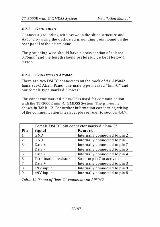
There are two DSUB9 connectors on the back of the AP5042 Inmarsat-C Alarm Panel, one male type marked “Inm-C” and one female type marked “Power”. The connector marked “Inm-C” is used for communication with the TT-3000E mini-C GMDSS System. The pin-out is shown in Table 12. For further information concerning wiring of the communication interface, please refer to section 4.4.7.
Female DSUB 9 pin connector marked “Inm-C” Pin Signal Remark 1 GND Internally connected to pin 2 2 GND Internally connected to pin 1 3 Data + Internally connected to pin 7 4 Data - Internally connected to pin 5 5 Data - Internally connected to pin 4 6 Termination resistor Strap to pin 7 to activate 7 Data + Internally connected to pin 3 8 +9V input Internally connected to pin 9 9 +9V input Internally connected to pin 8
Table 12 Pinout of "Inm-C" connector on AP5042
70/97

TT-3000E mini-C GMDSS System Installation Manual The connector marked “Power” is used for: 1) Connecting power to the internal electronics of the alarm
panel (the isolated RS485 interface is powered through connector “Inm-C”).
2) Configuration of Node ID address on the RS485 network. As up to four AP5042’s can be connected to the same cable, they need to have their own unique address in the rang 0-3.
3) Connection to the Service Interface. The pin-out of the “Power” connector is shown in Table 13.
Male DSUB 9 pin connector marked “Power” Pin Signal Remark 1 Node ID 1 GND GND for Node ID 1 selection 2 S-RX RS232 Service i/f RX (input) 3 S-TX RS232 Service i/f TX (output) 4 Node ID 1 Bus address selection pin 5 S-GND RS232 Service i/f GND 6 DC- 7 DC+
Nominal voltage 24V DC. Can operate from 8V to 32V DC.
8 Node ID 0 GND GND for Node ID 0 selection 9 Node ID 0 Bus address selection pin
Table 13 Pinout of "Power" connector on AP5042
4.7.3.1 AP5042 POWER CONNECTION
Connect 24VDC between “Power” pin 6 (negative) and pin 7 (positive). Do not connect the shield of the power supply cable at the alarm panel. It should be connected to ground at the source only. The typical current drawn is 11mA@24VDC with the display lit as shown in Figure 48. With full activity the maximum current will be around 36mA@24VDC. Note 1: The unit is internally protected against reverse polarity.
71/97

TT-3000E mini-C GMDSS System Installation Manual Note 2: The power supply is isolated from the box enclosure as well as from the RS485 interface.
4.7.3.2 AP5042 NETWORK ADDRESS CONFIGURATION
The first AP5042 connected to the TT-3000E mini-C GMDSS System only needs external power to operate. Subsequent AP5042’s need to get the address pins strapped according to Table 14.
ID Node ID 1 Node ID 0 3 (1st AP5042) Floating
Floating
2 (2nd AP5042) Floating Strap to Node ID 0 GND
1 (3rd AP5042) Strap to Node ID 1 GND
Floating
0 (4th AP5042) Strap to Node ID 1 GND
Strap to Node ID 0 GND
Table 14 Node ID adressing
4.7.3.3 AP5042 SERVICE INTERFACE
Normally there is no need to access the RS232 service interface, but in case it’s necessary, the easiest method is to make a cable adapter as shown in Figure 47.
72/97

TT-3000E mini-C GMDSS System Installation Manual
Figure 47 RS232 Adapter Cable for Service Interface
The terminal settings are 38400, N, 8, 1. If connected using Windows HyperTerminal® or equivalent, the following will be seen during power up: Thrane & Thrane (c), Alarm panel, AP5042 Reset by power-up Panel node ID : 3 :
To get a list of available commands, type “help<cr>”.
4.7.4 AP5042 INITIAL CHECK AND CONFIGURATION
Pressing and holding the Test button will make all light indicators and the alarm button flash. Pressing any other button while holding the Test button, will sound the buzzer enabling verification of the buttons and the audible indicator.
73/97
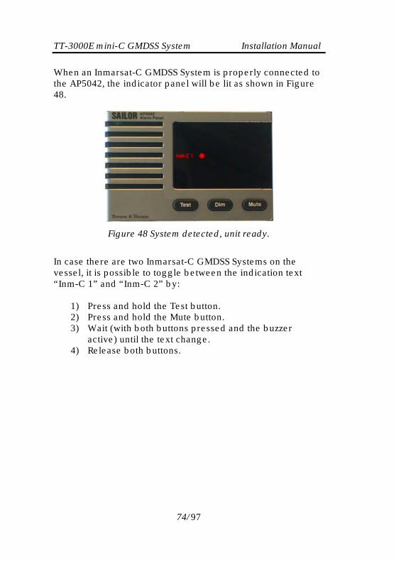
TT-3000E mini-C GMDSS System Installation Manual When an Inmarsat-C GMDSS System is properly connected to the AP5042, the indicator panel will be lit as shown in Figure 48.
Figure 48 System detected, unit ready.
In case there are two Inmarsat-C GMDSS Systems on the vessel, it is possible to toggle between the indication text “Inm-C 1” and “Inm-C 2” by:
1) Press and hold the Test button. 2) Press and hold the Mute button. 3) Wait (with both buttons pressed and the buzzer
active) until the text change. 4) Release both buttons.
74/97
TT-3000E mini-C GMDSS System Installation Manual 4.8 TT-3042C REMOTE ALARM/DISTRESS BOX
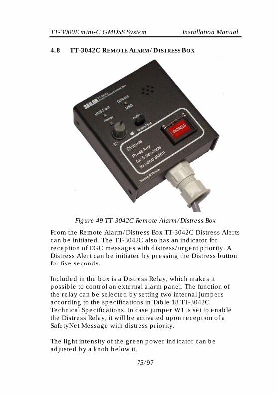
Figure 49 TT-3042C Remote Alarm/Distress Box
From the Remote Alarm/Distress Box TT-3042C Distress Alerts can be initiated. The TT-3042C also has an indicator for reception of EGC messages with distress/urgent priority. A Distress Alert can be initiated by pressing the Distress button for five seconds. Included in the box is a Distress Relay, which makes it possible to control an external alarm panel. The function of the relay can be selected by setting two internal jumpers according to the specifications in Table 18 TT-3042C Technical Specifications. In case jumper W1 is set to enable the Distress Relay, it will be activated upon reception of a SafetyNet Message with distress priority. The light intensity of the green power indicator can be adjusted by a knob below it.
75/97

TT-3000E mini-C GMDSS System Installation Manual
4.8.1 MOUNTING
Fic Iti
5
105
5
9.5
9.576
25.5
9.5
103
1110111 51135
All dimensions are in millimetres
B: Screwholes for console mounting, 4
A: Screwholes for wall mounting, 4
Alternativ cable hole
Console mounting hole
27
80
18
9.5 B
A
A
A
6
B
A
B
6
B
Figure 50 TT-3042C Mounting stencil.
asten the TT-3042C Remote Alarm/Distress Box from the nside or by using the mounting bracket, which makes onsole mounting possible.
f required, the cable relief are easily moved from the end of he TT-3042C to the bottom feed hole for hidden cable nstallation.
76/97

TT-3000E mini-C GMDSS System Installation Manual 4.8.2 CABLE CONNECTION
It is possible to connect 3 TT-3042C’s to the TT-3616C GMDSS Interconnection Box, from which they are supplied with power and control signals. The cable used has to be in compliance with the specifications in Table 18 TT-3042C Technical Specifications. Connect each wire as indicated by the label and in accordance with the wire colour codes chosen (refer to 4.4.6 Connecting TT-3042C to TT-3616C).
Figure 51 TT-3042C connector label
Do not connect the cable screen and make sure it does not short circuit anything.
77/97

TT-3000E mini-C GMDSS System Installation Manual
5 TEST OF THE SYSTEM This section provides information on how to perform system checks as well as help for troubleshooting. Concerning the initial start up and use of the TT-3606E Message Terminal, please refer to the user manual, ref. [1].
5.1 BASIC SYSTEM VERIFICATION
The TT-3616C Interconnection Box has 6 light emitting diodes (LED’s) to provide basic installation and troubleshooting help. The location of the LED’s is shown in Figure 52.
Spare fuse
5 Amp fuse
Figure 52 TT-3616C LED's and fuses locations.
5.1.1 DC IN LED
When applying power to the TT-3616C, the “DC in” LED will light up provided the fuse is OK. In case the LED does not light up, then:
78/97

TT-3000E mini-C GMDSS System Installation Manual
1) Check the fuse. If blown, check for short circuits on the cabling towards the TT-3026C mini-C Transceiver. Check for obvious visual errors on the TT-3616C itself (wire fragments, burnt areas etc.). Turn off the power supply before replacing the fuse. Note, that a spare fuse is available as indicated in Figure 52.
2) Check the wiring. 3) Check the power supply source.
5.1.2 3026 ON LED
The “3026 on” LED indicate, that the TT-3026C mini-C Transceiver is turned on. In case the LED does not light up, then:
1) Check, that the “DC in“ LED is on. 2) Check, that the “Remote on/off” terminal in J602 is
connected to DC- (if not, then the system is supposed to be turned off).
3) Check the mini-C Transceiver cabling. 4) Check that the supply voltage measured on J602
between DC- and DC+ is above 10.5 VDC. 5) Toggle “remote on/off” by leaving it floating for 1
second before reconnecting it to DC-.
5.1.3 3616C OK LED
For normal operation the “3616C OK” LED should be steady on when the system is powered. A flashing “3616C OK” LED indicates a software update in progress or a missing application software (could be a result of an aborted software update).
5.1.4 3026 OK LED
This LED is controlled by software and can only be trusted provided the “3616C OK” LED is steadily lit. The “3026 OK” LED should be steadily lit to indicate, that error free communication is detected between TT-3616C and TT-3026C. After power up this LED will be flashing until
79/97
TT-3000E mini-C GMDSS System Installation Manual correct communication with TT-3026C is established (duration approximately 10 seconds). If the “3026 OK” LED flashes continuously, then:
1) Check that the TT-3026C mini-C Transceiver is actually powered on by checking the “3026 on” LED.
2) Check the Transceiver cable, especially the following wires: Black/Blue, Grey, Black/Yellow & Black/Gray.
5.1.5 SSAS OK LED
This LED is controlled by software and can only be trusted provided the “3616C OK” LED is steadily lit. If the SSAS option is not installed, the “SSAS OK” LED will be flashing. If the SSAS option is correctly installed, the LED will be steadily lit. Refer to ref. [3] for further information.
5.1.6 GMDSS OK LED
This LED is controlled by software and can only be trusted provided the “3616C OK” LED is steadily lit. When one or more distress alarm panels are installed, the “GMDSS OK” LED should be steadily lit. In case the “GMDSS OK” LED is flashing, then:
1) Check that the alarm panels are correctly wired. 2) Check that the +9VDC is not overloaded (shorted) by
measuring more than 8V between +9V DC and GND on each of the connectors J901, J902, J903 & J302. If so, remove the overload. Each of the connectors J901, J902, J903 & J302 are equipped with a self reset able fuse, thus after removal of the overload the voltage should get back to normal.
80/97

TT-3000E mini-C GMDSS System Installation Manual Note, that some errors can only be detected when the Distress button is pressed. To perform such a test, refer to section 5.2.
5.2 DISTRESS BUTTON TEST
When the TT-3000E mini-C GMDSS System is fully installed, it is recommended to do a distress button test. The Distress Test Mode facility in the TT-3606E Message terminal (Alt - O, E) allows test of the Distress Buttons, Distress LED's and wiring. When Distress Test Mode option is selected the Distress Test Mode message is displayed:
Test Mode Yes No Distress buttons are under test. Cancel the test mode if a real distress alert needs to be sent. Cancel?
Please notice that the message displayed by the Message Terminal asks the operator if distress test mode should be cancelled. Do not answer yes to this question unless you are absolutely sure that you have completed distress testing. In Distress Test Mode the Distress Buttons can be activated and tested without issuing Distress Alerts. Distress Test Mode is cancelled by pressing the Esc key. After Distress Test Mode is terminated activating the Distress Buttons will again result in a Distress Alert being send.
5.2.1 TT-3042C REMOTE ALARM/DISTRESS BOX
When Distress Test mode is initiated the Remote Alarm Box starts a test sequence. In this sequence the Distress Msg LED, the buzzer and the MES Fault LED are activated one at a time. Test of the Distress Button on the Remote Alarm Box: Please note that the transceiver has to be in Distress Test Mode before this test is performed. Otherwise a real Distress Alert is transmitted.
81/97
TT-3000E mini-C GMDSS System Installation Manual Pressing the Distress button will make the Distress LED flash and will activate an intermediate acoustic signal. If the Distress button is held for at least 5 seconds the acoustic signal will stop and the Distress LED will light constantly to indicate that a Distress Alert would have been send in case Distress Test Mode had not been activated. Shortly after, the cyclic activation of the Distress Msg LED, the buzzer and the MES Fault LED will continue. The light in the Distress button can be switched off by pressing the Reset/Test button.
5.2.2 TT-3042CP REMOTE ALARM/DISTRESS BOX
Please follow the same procedure as for TT-3042C.
5.2.3 AP5042 INMARSAT-C ALARM PANEL
When Distress Test mode is initiated, the text “Test” will be shown in green letters on the display line. A cyclic test sequence will:
1) Switch on the “Distress” text (5 seconds). 2) Sound the buzzer (5 seconds). 3) Switch off the buzzer and the “Distress” text and
switch on the “Fault” text (5 seconds). 4) Switch off the “Fault” text.
All other segments on the display line will be lit constantly during the test. Test of the Distress Button on the AP5042: Please note that the transceiver has to be in Distress Test Mode before this test is performed. Otherwise a real Distress Alert is transmitted. Pressing the Distress button will make the distress button flash and will activate an intermediate acoustic signal. If the Distress button is held for at least 5 seconds the acoustic signal will stop and the distress button will be lit constantly to indicate that a Distress Alert would have been send in case Distress Test Mode had not been activated. Shortly after, the
82/97
TT-3000E mini-C GMDSS System Installation Manual cyclic activation of the “Distress” text, the buzzer and the “Fault” text will continue.
5.3 LINK TEST
A link test (or PVT test) tests the satellite link from the transceiver to the Land Earth Station. Prior to initiating a Link Test, make sure the TT-3026C mini-C Transceiver is properly commissioned (refer to section 3) and logged in (‘Options Login’). A link test is initiated by clicking ‘Options Link test’. Note, that it may take up to one minute for the information about the latest Link Test to be updated. Click ‘Activate’ to start the test. After a while the window will be updated with the text: “Automatic test mode: Normal communication disabled. Do not press any distress buttons unless you are in distress”. The printer will print a message saying Link Test request issued, then a Link Test request successful and a Link Test started. When receiving the results the screen will display: Link Test finished and the results will be printed out. Press ESC to leave the Link Test window after completion of the test. In case the Link Test fails, then make sure, that the signal strength as indicated on the main window is OK and then try performing another Link Test.
5.4 TEST OF BACKUP SUPPLY
Correct functionality of the backup supply should be tested.
83/97
TT-3000E mini-C GMDSS System Installation Manual When using the N163S Power Supply, simply switch of the mains supply on the switch found on the front of the unit. Observe, that the system continues to work uninterrupted from the 24V DC backup battery.
84/97

TT-3000E mini-C GMDSS System Installation Manual
6 MAINTENANCE GUIDELINES When properly installed the system needs no maintenance. After approximately 10 years the internal batteries in the TT-3026C and the TT-3606E has to be replaced, and both the transceiver and the message terminal must be sent for service.
6.1 HANDLING PRECAUTIONS
• Do not expose the transceiver’s parting line (the blue styling gasket) & connector to high-pressure water jets.
• Exposure of chemical containing alkalis may result in physical degradation of the transceiver.
• Do not expose the transceiver to acid curing silicone. • Avoid contact with solvents.
Do not paint the transceiver. If it is absolutely necessary to paint the transceiver, ideally water-based paints or paint system based on mild solvents should be selected.
85/97

TT-3000E mini-C GMDSS System Installation Manual
7 APPENDIX A
7.1 MOUNTING STENCIL
Figure 53 Mounting stencil
For connector: predrilled hole 32mm (1.26”) diameter A: 3 x predrilled holes 5mm (0.2”) diameter for M4 screws.
86/97

TT-3000E mini-C GMDSS System Installation Manual
8 APPENDIX B
8.1 TT-3026C CABLE INFORMATION
The description and functions of the TT-3026C mini-C Transceiver cable can be seen in Table 15.
Wire colour Function Description
2 x Red 1mm2 DC + 12-24 VDC
2 x Black 1mm2 DC - DC -
Yellow ON/OFF Remote ON/OFF
White GND GND
Orange GND GND
Black/Violet 3V3 out 3V3 out max. 100mA. for terminal equipment
Black/Blue Grey Black/Yellow Black/Grey Brown Black/Green
I/O port 1 - 2 - 3 - 4 - 5 - 6
1 to 4 reserved.
5 to 6 user configurable 3.3V I/Os. 5V tolerant. Each open-collector output sinks 25mA.
Green RD ** RS232 Receive
Black/Red TD ** RS232 Transmit
Violet RTS ** RS232 Request to send
Blue CTS ** RS232 Clear to send
Table 15 TT-3026C cable pin assignment
** DCE (Data Communication Equipment) naming.
87/97

TT-3000E mini-C GMDSS System Installation Manual
9 APPENDIX C Appendix C holds technical specification for the following units:
- TT-3026C - TT-3606E - TT-3042C - TT-3616C - AP5042
88/97

TT-3000E mini-C GMDSS System Installation Manual 9.1 TT-3026C SPECIFICATIONS
Model TT-3026C
General Specifications Meets all INMARSAT specifications for the
Inmarsat mini-C Network for Land mobile and
Maritime terminals.
R&TTE
Transmit Frequency 1626.5 to 1660.5 MHz. note 1
Receive Frequency 1525.0 to 1559.0 MHz. note 1
Channel Spacing 5 / 2.5 / 1.25 kHz.
Modulation 1200 symbols/sec BPSK.
Ambiguity Resolution Unique word.
Coding R ½ K=7 convolutional code, (interleaved code
symbols RX).
Data Rate 600 bit/sec.
RX Frame Length 8.64 seconds.
TX Signalling Access Mode Slotted ALOHA.
TX Message Channel TDMA & FDMA, interleaved code symbols.
Terminal Interface EIA/TIA-232-E DTE interface. CCITT
Rec.V.24/28, 4800-115200 Baud IA-5 code
I/O Interface:
Six dedicated In/Out pins.
Open-collector. Sinks 25 mA each.
System Set-up S-RAM Battery backup
DC Power Source Floating DC
Nominal voltage range is 12V to 24V
Working voltage range is 10.5V to 32V
Max limit 100VA
Max current 4A
Max power 32W
Power: RX: 1.8W ,TX: 23 W @ 12V supply
Fuse Self recovering Poly fuse
Ambient Temperature -35°C to 55°C operating
-40°C to 80°C storage.
Dimensions Ø=163 mm H: 143 mm
Weight 1.10 kg Note 1: Inmarsat frequencies: TX: 1626.5 – 1646.5 MHz RX: 1530 – 1545 MHz
89/97

TT-3000E mini-C GMDSS System Installation Manual
Operating system The TT-3026C mini-C transceiver makes use of eCos™
operating system.
Inmarsat-C
Protocol support
Message transmission and reception with IA-5, ITA-2 and
binary transfer to/from the following destinations:
Telex
PSTN (telephone modems and fax modems)
PSDN (X.25 network)
EGC message reception with automatic geographical area
selection.
Polling and data reporting with automatic transmission of
position reports down to a recommended minimum of 1 per 5
minutes.
Special Access Codes
DNID Messaging
Program Unreserved Data reporting
Transmit message size: Max 10Kbyte
Receive storage: > 32 Kbytes.
TT-3026C
mini-C
Transceiver
Inmarsat-C/GPS omnidirectional antenna, RHC polarised.
G/T: -23.7 dB/K at 5° elevation
EIRP: 7 dBW dB at 5° elevation.
Temperature: -35°C to 55°C operating,
-40°C to 80°C storage.
Maximum
transmission
length
10 Kbytes.
Solar Radiation Max. flux density 1200W/m2.
Precipitation Up to 100 mm/hour, droplet size 0.5 to 4.5 mm
Ice Up to 25 mm.
Velocity Max velocity up to 140 km/hour (87mph).
Vibration
Operational
Random 5-20 Hz: 0.005 g2/Hz
20-150 Hz: -3dB/oct. (0.5g RMS).
Vibration Survival Random 5-20 Hz: 0.05 g2/Hz
20-150 Hz: -3dB/oct. (1.7g RMS).
Shock Half sine 20g/11ms
Table 16 TT-3026C Technical Spectifications
90/97

TT-3000E mini-C GMDSS System Installation Manual 9.2 TT-3606E SPECIFICATIONS
Processor 386SX-40MHz
RAM 4 MB
Flash DISK 2 MB
Display 10.4” Color TFT flatpanel, 640x480
Floppy drive 3.5”
Keyboard i/f 5-pin mini-DIN
Parallel printer port 25 pin SubD female connector
Serial port COM1 9 pin SubD male connector, DTE type
Serial port COM2 9 pin SubD male connector, DTE type
Environmental Meets or exceeds all INMARSAT specifications
for the Inmarsat-C Network for SOLAS with
distress call functions. (CN114 and IEC 60945
requirements). Meets CE-marking (1997)
requirements. Wheel Mark approved
Power Source 10.5 to 32 V floating DC, 15 pin SubD female
Power Consumption App. 20 Watts, maximum
App. 13 Watts, typical
Fuse Internal automatic recovering poly fuse
Ambient Temperature -20°C to 55°C operating
-40°C to 80°C storage.
Compass safe distance 50 cm
(measured in accordance with the standards
specified in ISO/R 694, Method B)
Dimensions H x W x D 221x 297 x 114.5 mm w/o bracket
256 x 297 x 114.5 mm w bracket at vertical
position
Weight 3.1 kg (including mounting bracket)
Table 17 TT-3606E Message Terminal Specifications
91/97

TT-3000E mini-C GMDSS System Installation Manual 9.3 TT-3042C SPECIFICATIONS
Model TT-3042C, Remote Alarm/Distress Box General Specifications The unit is in full compliance with the
Inmarsat CN114, IEC 60945 and Wheel Mark specifications.
Dimensions (H x W x D) 49 mm x 95 mm x 99 mm Weight 0.32 Kg Mountings Wall mounting, 4 holes Ø4.0 mm
Mounting bracket for console, 4 holes Ø4.0 mm
Power requirements 7.5V - 12V DC, Standby: 0.1W @ 9VMax.: 0.5W @ 9V
Cable length / Type Max. 100m / 8 wire, screened signal cable, 0.25mm2 or better.
Connector Internal screw terminals Distress/MES Fault Relay Max. switching: 2A or 60W or 220V AC Distress Relay jumpers Enable; W1: 1-2,
Disable; W1: 2-3 †† Activated: Shorted; W2: 1-2 ††, Open; W2: 2-3
MES Fault Relay jumpers Enable; W3: 1-2, Disable; W3: 2-3 †† Activated: Open; W4: 1-2 ††, Shorted; W4: 2-3
Temperature -25°C to 55°C operating, -40°C to 80°C storage
Relative humidity 95% non-condensing at 40°C Vibration operational Random vibrations: 5-20 Hz:0.005 g²/Hz
20-150 Hz:-3 dB/oct (0.5 g rms.) Sinusoidal vibrations: 2-15.8 Hz: 2.54 mm peak ampl. 10-100 Hz: 1.0 g peak acceleration
Vibration survival Random vibrations: 5-20 Hz:0.05g²/Hz 20-150 Hz:-3 dB/oct (1.7g rms.) Sinusoidal vibrations: 2-15.8 Hz:2.54 mm peak ampl. 10-100 Hz: 1.0g peak acceleration
Shock Half sine: 20g/11ms
Table 18 TT-3042C Technical Specifications
††: Factory setting
92/97
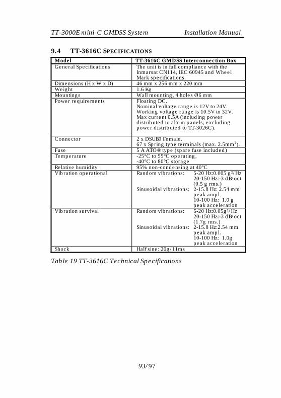
TT-3000E mini-C GMDSS System Installation Manual 9.4 TT-3616C SPECIFICATIONS
Model TT-3616C GMDSS Interconnection Box General Specifications The unit is in full compliance with the
Inmarsat CN114, IEC 60945 and Wheel Mark specifications.
Dimensions (H x W x D) 46 mm x 256 mm x 220 mm Weight 1.6 Kg Mountings Wall mounting, 4 holes Ø6 mm Power requirements Floating DC.
Nominal voltage range is 12V to 24V. Working voltage range is 10.5V to 32V. Max current 0.5A (including power distributed to alarm panels, excluding power distributed to TT-3026C).
Connector 2 x DSUB9 Female. 67 x Spring type terminals (max. 2.5mm2).
Fuse 5 A ATO® type (spare fuse included) Temperature -25°C to 55°C operating,
-40°C to 80°C storage Relative humidity 95% non-condensing at 40°C Vibration operational Random vibrations: 5-20 Hz:0.005 g²/Hz
20-150 Hz:-3 dB/oct (0.5 g rms.) Sinusoidal vibrations: 2-15.8 Hz: 2.54 mm peak ampl. 10-100 Hz: 1.0 g peak acceleration
Vibration survival Random vibrations: 5-20 Hz:0.05g²/Hz 20-150 Hz:-3 dB/oct (1.7g rms.) Sinusoidal vibrations: 2-15.8 Hz:2.54 mm peak ampl. 10-100 Hz: 1.0g peak acceleration
Shock Half sine: 20g/11ms
Table 19 TT-3616C Technical Specifications
93/97
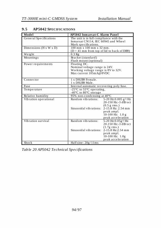
TT-3000E mini-C GMDSS System Installation Manual 9.5 AP5042 SPECIFICATIONS
Model AP5042 Inmarsat-C Alarm Panel General Specifications The unit is in full compliance with the
Inmarsat CN114, IEC 60945 and Wheel Mark specifications.
Dimensions (H x W x D) 100 mm x 100 mm x 32 mm. (D = 41 mm from top of lid to back of DB9)
Weight 0.3 Kg Mountings Bracket (standard)
Flush mount (optional) Power requirements Floating DC.
Nominal voltage range is 24V. Working voltage range is 8V to 32V. Max current 105mA@8VDC
Connector 1 x DSUB9 Female. 1 x DSUB9 Male.
Fuse Internal automatic recovering poly fuse. Temperature -25°C to 55°C operating,
-40°C to 80°C storage Relative humidity 95% non-condensing at 40°C Vibration operational Random vibrations: 5-20 Hz:0.005 g²/Hz
20-150 Hz:-3 dB/oct (0.5 g rms.) Sinusoidal vibrations: 2-15.8 Hz: 2.54 mm peak ampl. 10-100 Hz: 1.0 g peak acceleration
Vibration survival Random vibrations: 5-20 Hz:0.05g²/Hz 20-150 Hz:-3 dB/oct (1.7g rms.) Sinusoidal vibrations: 2-15.8 Hz:2.54 mm peak ampl. 10-100 Hz: 1.0g peak acceleration
Shock Half sine: 20g/11ms
Table 20 AP5042 Technical Specifications
94/97
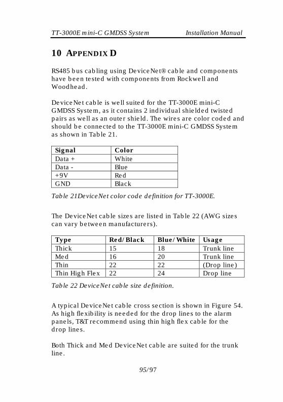
TT-3000E mini-C GMDSS System Installation Manual
10 APPENDIX D RS485 bus cabling using DeviceNet® cable and components have been tested with components from Rockwell and Woodhead. DeviceNet cable is well suited for the TT-3000E mini-C GMDSS System, as it contains 2 individual shielded twisted pairs as well as an outer shield. The wires are color coded and should be connected to the TT-3000E mini-C GMDSS System as shown in Table 21.
Signal Color Data + White Data - Blue +9V Red GND Black
Table 21DeviceNet color code definition for TT-3000E.
The DeviceNet cable sizes are listed in Table 22 (AWG sizes can vary between manufacturers).
Type Red/Black Blue/White Usage Thick 15 18 Trunk line Med 16 20 Trunk line Thin 22 22 (Drop line) Thin High Flex 22 24 Drop line
Table 22 DeviceNet cable size definition.
A typical DeviceNet cable cross section is shown in Figure 54. As high flexibility is needed for the drop lines to the alarm panels, T&T recommend using thin high flex cable for the drop lines. Both Thick and Med DeviceNet cable are suited for the trunk line.
95/97

TT-3000E mini-C GMDSS System Installation Manual
Figure 54 DeviceNet cable cross section - Thick
The T-Connectors tested are: • Allen-Bradley (Rockwell) DeviceNet T-Connector 1485-P1N5-MN5R1 • BradConnectivity (Woodhead) Media Bus Drop TEE DN3020
Figure 55 Rockwell DeviceNet T-Connector
The termination plugs tested are: • Brad Connectivity (Woodhead) female termination resistor DN150 • Brad Connectivity (Woodhead) male termination resistor DN100
96/97

TT-3000E mini-C GMDSS System Installation Manual The field installable cable connectors tested are: • Brad Connectivity (Woodhead) female conn. field install 1A5000-34DN • Brad Connectivity (Woodhead) male conn. field install 1A5006-34DN
Figure 56 Field installable DeviceNet connector.
+++
97/97