
This user manual describes all proceedings concerning theThis user manual describes all proceedings...
160
Transcript of This user manual describes all proceedings concerning theThis user manual describes all proceedings...


This user manual describes all proceedings concerning the operations of this drive unit in details as much as possible. However, it is impractical to give particular descriptions for all unnecessary or unallowable system operations due to the manual text limit product specific applications and other causes. Therefore, the proceedings not indicated herein should be considered impractical or unallowable.
This user manual is the property of GSK CNC Equipment Co., Ltd. All rights are reserved. It is against the law for any organization or individual to publish or reprint this manual without the express written permission of GSK and the latter reserves the right to ascertain their legal liability.

DAP、DAY Series Spindle Servo Drive Unit User Manual
II
Preface
Dear user, It’s our great pleasure for your patronage and selects our company
products! The capability, installation, connection, debugging, use as well as
maintenance of the spindle servo drive unit DAP03, DAY3025 and DAY3100 are described in this manual. In order to guarantee the product safety and the work can be effectively performed, the user must read carefully the manual before installing and using the drive unit.
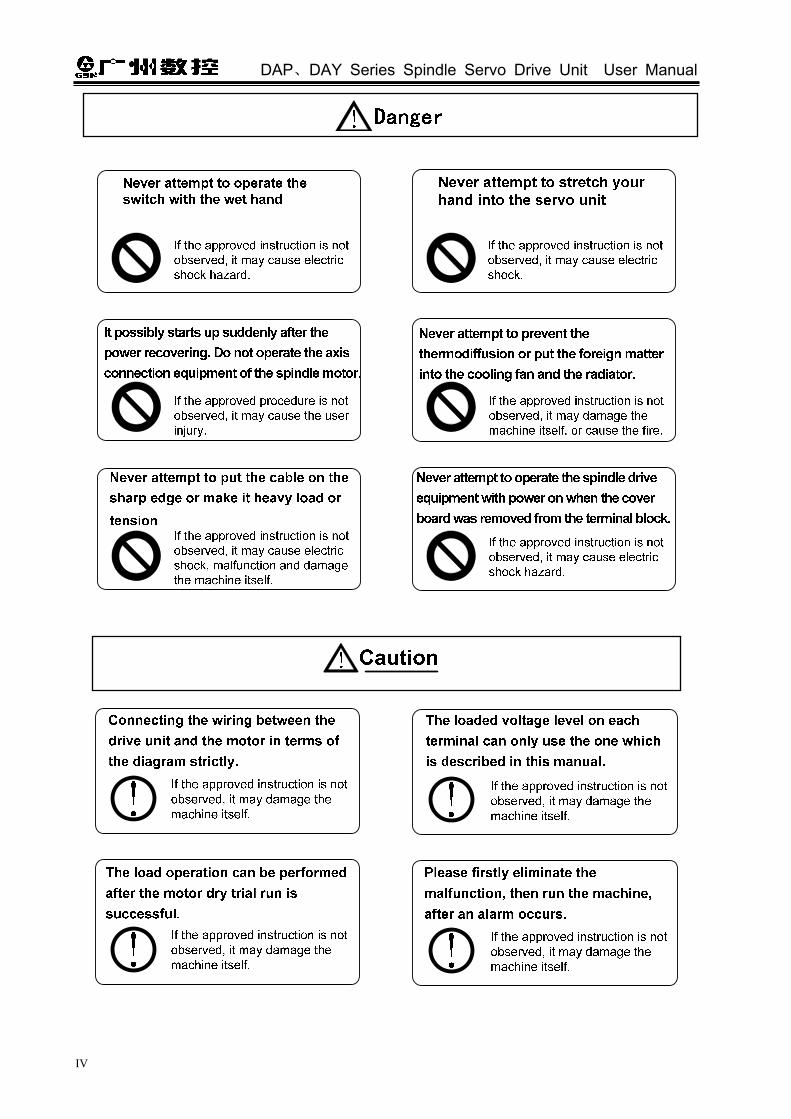
To avoid the injury of the operators and the others, and the damage of the drive device, please pay special attention to the following alarms before reading this manual:
Incorrect operation may result in death or severe injury.
Operating the machine incorrectly may result in injured or flesh wounded, as well as the loss in material.
If the approved procedure is not observed, it may result in the machine behaving unexpectedly.
The vital requests and important indications are indicated during operating.
It means Forbiddance (absolutely can not be done)
It means Compulsion (must be done)
Notice

Security Caution
III
DAP、DAY Series Spindle Servo Drive Unit User Manual
IV

Security Caution
V

DAP、DAY Series Spindle Servo Drive Unit User Manual
VI
Safety Responsibility
Manufacturer’s Responsibility
——Be responsible for the danger which should be eliminated and/or controlled on
design and configuration of the provided Servo drive unit and accessories.
——Be responsible for the safety of the provided Servo drive unit and accessories.
——Be responsible for the provided information and advice for the users.
User’s Responsibility
——Be trained with the safety operation of Servo drive unit and familiar with the safety
operation procedures.
——Be responsible for the dangers caused by adding, changing or altering to the
original Servo drive units and the accessories.
——Be responsible for the failure to observe the provisions for operation, adjustment,
maintenance, installation and storage in the manual.
All specifications and designs herein are subject to change without
further notice.
This manual is reserved by end user.
We are full of heartfelt gratitude to you for supporting us in the use of
GSK’s products.
Contents
VII
Contents CHAPTER ONE PRODUCT INTRODUCTION.................................................................................1
1.1 Foundation Knowledge ................................................................................................................... 1
1.2 The Confirmation of the Products Arrival ..................................................................................... 7
1.2.1 Spindle Servo Motor ............................................................................................................. 7
1.2.2 Drive Unit ............................................................................................................................... 8
1.3 Technical Specification.................................................................................................................. 10
1.3.1 Spindle Motor Technical Specification............................................................................. 10
1.3.2 The Technical Specification of Servo Drive Unit ............................................................ 11
1.4 An Instruction of Placing an Order............................................................................................... 13
1.4.1 The Specification for the Item ........................................................................................... 13
1.4.2 Factory Standard Accessories .......................................................................................... 14
1.4.3 Brake Resistance................................................................................................................ 15
CHAPTER TWO INSTALLATION ..................................................................................................17
2.1 Spindle Servo Motor ...................................................................................................................... 17
2.1.1 The Installation Dimension of the Spindle Motor ........................................................... 17
2.1.2 The Installation of the Spindle Motor ............................................................................... 18
2.2 Drive Unit......................................................................................................................................... 19
2.2.1 The Installation Dimension of Drive Unit ......................................................................... 19
2.2.2 The Installation of the Drive Unit ...................................................................................... 21
CHAPTER THREE CONNECTION ................................................................................................24
3.1 The Connection of Peripheral Equipment .................................................................................. 25
3.2 Connection Scheme of the Drive Unit......................................................................................... 28
3.3 The Connection of Main Circuits.................................................................................................. 29
3.4 The Connection of Control Signals.............................................................................................. 32
3.4.1 CN1 Pin Definition .............................................................................................................. 32
3.4.2 Signal Input Explanation .................................................................................................... 34
3.4.3 Signal Output Explanation ................................................................................................. 39
3.5 The Connection of Feedback Signal ......................................................................................... 43
3.5.1 Pin Definitions of CN2 and CN3 ....................................................................................... 43
3.5.2 The Pin Specifications both CN2 and CN3 ..................................................................... 44
3.6 The Wiring Example in Different Workings ................................................................................ 46
3.6.1 Wiring in Speed Mode........................................................................................................ 46
3.6.2 Wiring in Position Working ................................................................................................ 48
3.6.3 Speed/Position Working Wiring ........................................................................................ 49

DAP、DAY Series Spindle Servo Drive Unit User Manual
VIII
CHAPTER FOUR DISPLAY AND OPERATION............................................................................51
4.1 Operation Panel .............................................................................................................................. 51
4.2 Menu Display .................................................................................................................................. 52
4.3 State Monitoring.............................................................................................................................. 52
4.4 Parameter Setting........................................................................................................................... 56
4.5 Parameter Administration.............................................................................................................. 58
CHAPTER FIVE DEBUGGING ......................................................................................................60
5.1 Manual, JOG Operation................................................................................................................. 61
5.1.1 Manual Operation................................................................................................................ 62
5.1.2 JOG Operation..................................................................................................................... 63
5.2 Running in Speed Mode ................................................................................................................ 64
5.2.1 Analog Voltage Commands ............................................................................................... 64
5.2.2 Internal Digital Command .................................................................................................. 67
5.3 Position Mode Operation ............................................................................................................... 69
5.4 Speed/Position Mode Operation .................................................................................................. 72
CHAPTER SIX FUNCTION DEBUGGING .....................................................................................75
6.1 Basic Capability Parameter Debugging Description ................................................................. 75
6.1.1 Debugging Method.............................................................................................................. 75
6.1.2 The Application of Rigid Tapping ...................................................................................... 77
6.2 Shifting Between the Motor Rotation Directions ........................................................................ 78
6.3 Position Signal Output ................................................................................................................... 80
6.4 Brake Stop ....................................................................................................................................... 82
6.5 Function Debugging of the Position Mode.................................................................................. 83
6.5.1 Electronic Gear Ratio of Position Commands ................................................................ 83
6.5.2 Position Arrival Signal......................................................................................................... 84
6.6 Function Debugging in the Mode of Speed ................................................................................ 85
6.6.1 Orientation Function ........................................................................................................... 85
6.6.2 Analog Command Adjustment .......................................................................................... 90
6.6.3 Speed Arrival Signal ........................................................................................................... 92
6.6.4 Zero Clamping ..................................................................................................................... 93
6.6.5 Speed Command Electronic Gear Ratio ......................................................................... 94
CHAPTER SEVEN PARAMETER..................................................................................................96
7.1 Parameter Table ............................................................................................................................. 96
7.2 Details for the Parameter Significance ...................................................................................... 100
CHAPTER EIGHT ABNORMALITY AND TROUBLESHOOTING ...............................................111
8.1 An Abnormity May Occur When Using Improperly.................................................................. 111

Contents
IX
8.1.1 Speed Mode ...................................................................................................................... 111
8.1.2 Position Mode.................................................................................................................... 112
8.2 The Significance and Troubleshooting of Alarm Codes ......................................................... 113
8.3 No Displaying the Alarm Code of Troubleshooting ................................................................. 119
8.4 The Repair and Maintenance of the Servo Unit and the Servo Motor .................................... 121
Appendix A The Comparison Table of Type Parameters and Spindle Motors ......................122
Appendix B The Selection of Peripheral Equipment ...............................................................123
B.1 Breaker and Contactor (Required Equipment)........................................................................ 123
B.2 Three-phase AC Filter (Recommended Equipment).............................................................. 123
B.3 AC Reactor (Recommended Equipment) ................................................................................ 124
Appendix C The Wiring Diagram between the Spindle Servo Drive Unit and CNC System .125
C.1 The System Wiring Diagram between the Drive Unit and GSK218m ................................. 125
C.2 The Connection Illustration between the Drive Unit and GSK980TDa................................ 126
C.3 The Wiring Illustration between Drive Unit and GSK 980TD1(V2) ...................................... 129
C.4 The System Wiring Illustration between Drive Unit and GSK 983M.................................... 132
Appendix D DAP03C DAY3025C Spindle Servo Unit GSKLink Communication Function User Manual ............................................................................................................................................133
D.1 GSKLink Communication Function Connection and Setting ................................................... 133
D.2 Parameter List.............................................................................................................................. 135
D.3 The Significance and Troubleshooting of Alarm Codes ........................................................ 140
Software Supplement Explanation of DAY3000 (V1.09) and DAP03 (V1.08).............................146
Software Supplement Explanation of DAY3000 (V1.11) and DAP03 (V1.10).............................148

DAP、DAY Series Spindle Servo Drive Unit User Manual
X

Chapter One Product Presentation
1
CHAPTER ONE PRODUCT INTRODUCTION
1.1 Foundation Knowledge Spindle servo drive device fundamental
The spindle servo drive equipment (the following is abbreviated as servo equipment) is composed of the spindle servo drive unit and the spindle servo motor (three-phase AC servo motor, the following is abbreviated as servo motor). The drive unit is treated the three-phase AC integrated current as AC current (that is AC-DC), and ON or OFF is controlled by the switch tube, the approximate sine wave current (that is DC—AC) of the phase potential difference 120° may occur in the three-phase stator winding of the servo motor. A rotation magnetic field is formed of this current in the servo motor, and the servo motor rotor may be introduced a sensitive current based on the rotation magnetic filed, the electromagnetic torque drive motor rotor rotation may create based on the interaction between the rotation magnetic field and the induction current.
The higher current frequency of the servo motor winding is, the faster the speed of the servo motor is; the higher current magnitude of amplitude value of the servo motor winding is, the bigger the torque (torque=force × arm length) output by the servo motor is. The main circuit frame is as the figure 1-1, and the PG is an encoder.
.
Fig. 1-1 Drive unit main circuit frame
The basis structure of the spindle servo drive device The drive unit accepts the speed (or position) command of control equipment (It is also called the
instruction control unit). The frequency and magnitude of the servo motor winding current can be controlled, so that the speed (or corner) of the servo motor rotor approximates the speed (or position) command value, and the error between the actual value of the servo motor rotor speed (corner) and the command value which can be gained by examining the encoder of servo motor. The frequency and magnitude of the current flowing through the servo motor winding is continuously adjusted by the servo motor, so that the error between the actual value of servo motor rotor speed (or corner) and command value which should be controlled within the required range. The basic structure of the spindle servo equipment is as figure 1-2.

DAP、DAY Series Spindle Servo Drive Unit User Manual
2
Fig. 1-2 The basis structure of spindle servo device
The general concept of control Control: It is called control that the process making the characters (for example: speed) of
the object (for example: servo motor) reach or approximate the anticipated value, and the former object is called as the controlled; the character of the controlled object is regarded as controlled amount, and the unit to be achieved which is called controllable unit; the expected value (command value) of the controlled amount received from the control unit is called the given; the controlled amount is assumed to the input of control unit, which is affected the process of controlled amount, is called the feedback, check the unit of being controlled amount is called feedback unit.
The feedback can be divided into positive (same direction) and negative (reverse direction) based upon the controlled amount and the given direction output by the control unit. The drive equipment is composed of the control unit controlled by the controllable amount, the controlled object and the feedback unit. Drive units can be divided into closed-loop and open-loop equipments in terms of whether there is feedback unit or not or the position of the feedback unit in the drive unit. The closed-loop control equipments introduced in this manual are all negative feedback.
In the servo drive equipment introduced in this manual, the drive unit is control unit, the servo motor is controlled object, the motor speed (the corner of rotor) is controlled amount, the servo motor encoder is feedback unit, and the actual speed of the encoder motor detection is used for speed control to achieve the speed feedback. Therefore, the spindle servo drive belongs to the close-loop control equipment.
Open-loop control equipment: A feedback unit is not performed in control equipment; the actual value of controlled amount is not affected to the output of control unit. Such as the step motor drive equipment, the rotor of step motor should be varied from the current phase-sequence changes after the step motor drive unit outputs the current phase-sequence and changes. Generally, the motor rotor may not follow the current phase-sequence when the overload occurs or the high acceleration/deceleration issues, due to the step motor does not install speed or position feedback unit, eventually, the “stepout” may cause. Refer to the following fig.1-3.
Fig. 1-3 Open-loop control equipment
Control unit Power drive unit Motor Driving
machine
Feedback check
Given +
-
CNC equipment
Spindle servo drive equipment

Chapter One Product Presentation
3
Closed-loop control equipment: The controlled amount of control equipment is detected by the feedback unit and sent to the control unit, and the control equipment changes the controlled variable through controlling the output of the control unit. The close-loop control equipment is divided into the complete closed-loop control equipment and the semi-closed-loop control equipment based upon the check position of feedback unit. The feedback unit directly detects the controlled amount for feedback which is called the complete closed-loop control equipment (see the figure 1-4), and the mechanical position is regarded as the controlled amount, the grating rule installed on the machine is regarded as a position feedback unit, and the encoder mounted on the servo motor is treated as a speed feedback unit, and then the equipment achieves a complete closed-loop control in the mechanical position. If the grating rule is not mounted, the encoder of servo motor is simultaneously regarded as the position and speed feedback unit (see the figure 1-5). Therefore, this is a semi-closed-loop control equipment of a machine position.
Fig. 1-4 Complete closed-loop control equipment
Fig. 1-5 Semi-closed-loop control equipment
PID control: It is also called PID adjustment, which is common calculation of control unit is
treated the mathematical treatment for the input data (given, feedback). P is proportional, which is indicated that both input and output of control unit are composed of the linear proportional relation, the bigger the proportional control coefficient is, the more sensitive the system reacts, the less steady-state errors is (it can not be eliminated). The system vibration and unsteadiness may occur due to the excessive proportional control coefficient.
“I” means integral, it is indicated that the input of the control unit is affected to the time integral output (the input is gradually affected the output), the bigger the integral time constant is, the more steady the system is, and the steady-state error can be eliminated, but the system may respond slowly.
“D” means differential, it is indicated that the input differential (input the changeable slope) is affected to the output. The differential control can be forecasted the error, produced the advancing check function and reduce the follow error, as well improved the dynamic capability. The vibration and steadiness may cause due to the excessive differential coefficient. The proportion, integral and

DAP、DAY Series Spindle Servo Drive Unit User Manual
4
differential are interacted. The PID control parameters are adjusted to the balance for the system reaction rate, control accuracy and steadiness. Because the differential adjust is easily caused by the impact and vibration, the servo drive in this manual adopts PI adjustment, that is the proportion and integral are performed only.
The relative concept for serve control Three kinds of basis control modes of the servo drive equipment are available, such as: position,
speed and torque, the drive equipment is as Fig.1-6. Position control: The motor rotation direction and angle are given by using the numerical
pulse or data communication mode, the drive unit controls motor rotor that rotates a corresponding angle in terms of the given direction. The rotation angle (position) and speed can be controlled.
Speed control: The motor rotation direction and speed are given by using the analog voltage or data communication mode, the drive unit controls the motor rotor that rotates based upon the given direction and speed.
Torque control: The output torque size and direction are given by using the analog voltage or data communication mode, the rotor rotation direction and torque output size of motor are controlled by the drive unit.
Currently, the servo drive device introduced in this manual does not accept the signal given from torque, the torque control operation mode is not offered temporarily.
PG
Position feedback signal
-
+ Power amplification
Current adjustment
+ Speed adjustment
-
+ Position adjustment
-Command position Speed feedback
signalCurrent feedback
signal
Position controller
Speed controller
Current controller
Motor
Fig. 1-6 Tricyclic control system frame
Servo drive device capability index Servo drive device dynamic response characteristic: the reaction speed, dynamic control
error and stable control error of the servo drive equipment are performed when the specification or the load is changed. The response characteristic figure in which the servo drive device offers a step signal. (The actual line is given signal, and the broken line is the output signal of the drive unit equipment, same as below):

Chapter One Product Presentation
5
Fig. 1-7 Servo dynamic response curve
Rising time tr: It means that the time that the rotation output amount is risen from zero for the first time to 90% of steady-state value R (t) , and it also means the dynamic response rapidity.
Regulation time ts: The ±5% of steady-state value near to the step response curve steady-state value R (t) is regarded as the allowance error area. The required least time is the adjust time that the responding curve arrival does not overstep the error area, It is measured the regulation processing speed of the equipment.
Overshoot σ: It indicates that the speed output amount exceeds the rate between maximum speed D-value (Rmax (t)-R (t)) and stationary-state value R (t), it reflects relative stability of a servo device, and it also can be expressed by the percentage, that is:
%100)(
)()((%) max ×
−=
tRtRtR
σ
Steady-state error: The D-value of the equipment between the expected output steady-state
value and the actual output value are performed, after the equipment response is entered to the rotational speed.
Servo drive equipment static capability: In the drive control equipment, it is very important to stability. The steady-state capability index of servo drive equipment is a positioning accuracy, to be exact, the difference degree between the actual and expectative states are generated when the device transition is ended. The reasons affecting the servo drive device steady-state accuracy is both the errors of the position measure device and the system error, which is regardless of the structure and parameter of the system. Refer to the following Fig. 8.

DAP、DAY Series Spindle Servo Drive Unit User Manual
6
Fig. 1-8 Position servo static curve
Follow error: It is indicated that the position difference between the moved worktable position (command position) required by the command signal and the actual moved worktable position, that is, the fellow error = (the command position value) – (the value of actual position).
Servo rigid: The servo drive equipment is caused position error capability against the load interference.
The comparison between the spindle servo drive equipment and frequency-conversion drive equipment
Both the spindle drive device and the frequency-conversion drive can be carried out the switch AC—DC—AC and the drive three-phase AC motor. However, the spindle servo motor is performed an electromagnetic design in terms of the wider current frequency, and the valid speed adjustable range is wider; The allowable current frequency range of frequency-conversion motor is smaller, and the effective timing range is the narrower. An encoder installed on the spindle servo motor is regarded as feedback element, so the spindle servo drive equipment belongs to the closed-loop control device.
Generally, the frequency-conversion motor does not install an encoder belonging to an open-loop control device. The motor speed varies from the load change. The transformer can not control a motor to recover its speed like the spindle servo drive unit because the encoder detection speed and does not perform a feedback control. In order to reduce cost, normally, the overload capability of a transformer is 10%~20%; however the overload capability of the spindle servo drive unit is more than 50%. The stronger the overload capability is, the faster the acceleration and the responses.
The spindle servo drive equipment with advantages comparing with the frequency-conversion
drive equipment: It can be achieved both the speed and position control that because they are shared high
accuracy; The valid speed regulation range is wide; the effective torque can be output when its speed
is zero; The speed fluctuation is smaller and can be recovered immediately while the load is
changing; High overload, rapid response and high efficiency, and it adapts to the occasion of rapid
start and stop.

Chapter One Product Presentation
7
1.2 The Confirmation of the Products Arrival
Check each item after receiving the products immediately, if any problems, please contact the supplier or our company freely.
Checked item Remark
Check the drive unit and spindle motor, which are the ordered products;
It is confirmed by the drive unit and spindle motor’s nameplate.
Check whether the fittings are assembled;Confirm the content of packing list, if this content is inconsistent with the accessories, and refer to the section 1.4 for the order instruction.
Check whether the products are damaged due to the transportation;
The integrated appearance of the products should be complete and without damage.
Check whether the screws are loose. Check whether the screws are loose with the screwdriver
1. The damaged AC spindle drive unit or the incomplete accessories can not be
mounted; 2. The AC spindle drive unit should be matched with the spindle motor.
1.2.1 Spindle Servo Motor
Fig. 1-9
S2 30min
S1
Type:ZJY208-5.5BH-B5
DAP、DAY Series Spindle Servo Drive Unit User Manual
8
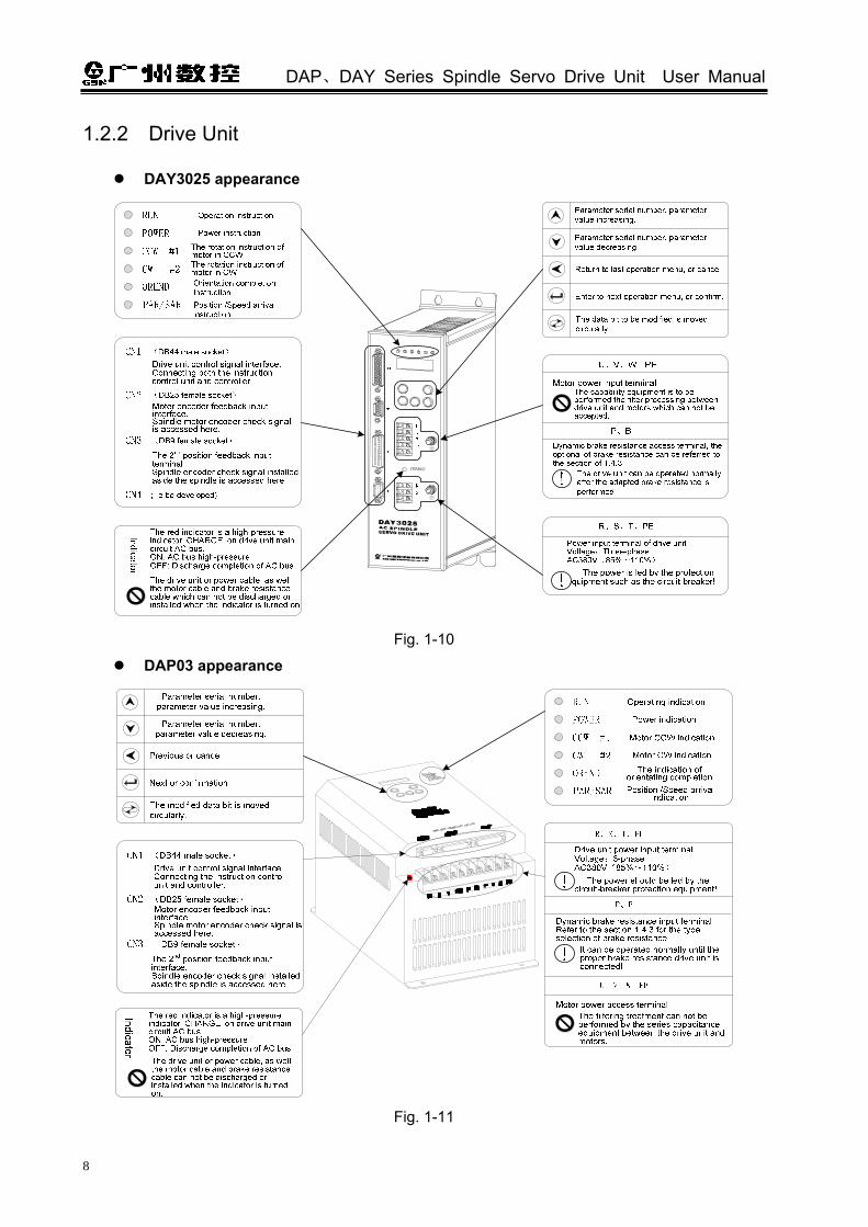
1.2.2 Drive Unit
DAY3025 appearance
Fig. 1-10
DAP03 appearance
Fig. 1-11
Chapter One Product Presentation
9
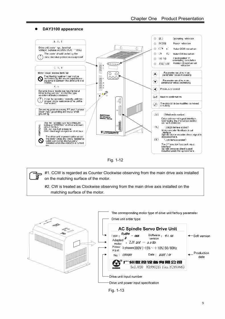
DAY3100 appearance
Fig. 1-12
#1. CCW is regarded as Counter Clockwise observing from the main drive axis installed on the matching surface of the motor.
#2. CW is treated as Clockwise observing from the main drive axis installed on the matching surface of the motor.
Fig. 1-13

DAP、DAY Series Spindle Servo Drive Unit User Manual
10
1.3 Technical Specification 1.3.1 Spindle Motor Technical Specification
Spec.
Item
ZJY208-2.2B
(Instead of
ZJY132-2.2)
ZJY208-3.7B
(Instead of
ZJY132-3.7)
ZJY208-5.5B
(Instead of
ZJY132-5.5)
ZJY208-7.5B
(Instead of
ZJY132-7.5)
ZJY265-7.5B
(Instead of
ZJY160-7.5)
ZJY265-11B
(Instead of
ZJY160-11)
ZJY265-15B
(Instead of
ZJY160-15)
Rated power (kW)
2.2 3.7 5.5 7.5 7.5 11 15
Drive unit voltage (V)
Three-phase AC380V(85%~110%) 50Hz/60Hz±1Hz
Rated current (A)
9.3 8.9 13.7 18.4 18 26 35
Rated frequency (Hz)
50 50 50 50 50 50 50
Rated torque (N.m)
14 24 35 48 49 72 98
30min power (kW)
3.7 5.5 7.5 11 11 15 18.5
30min Current (A)
13.6 13 18 25 26 34 42
30min torque (N.m)
24 35 48 70 74 100 123
Rated speed (r/min)
1500 1500 1500 1500 1500 1500 1500
Constant power range (r/min)
When the maximum speed is H: 1500~6000; and when the top speed is M: 1500~5000
The top speed (r/min)
M、H M、H M、H M、H M M M
Moment of inertia (kg·m2)
0.0103 0.0168 0.0238 0.0309 0.0413 0.0744 0.0826
Weight (kg) 49 51 66 77 89 107 125
Installation type
IM B5 or B3
Defense level
IP54(GB/T 4942.1—2001)
Chapter One Product Presentation
11
Spec.
Item
ZJY208-2.2B
(Instead of
ZJY132-2.2)
ZJY208-3.7B
(Instead of
ZJY132-3.7)
ZJY208-5.5B
(Instead of
ZJY132-5.5)
ZJY208-7.5B
(Instead of
ZJY132-7.5)
ZJY265-7.5B
(Instead of
ZJY160-7.5)
ZJY265-11B
(Instead of
ZJY160-11)
ZJY265-15B
(Instead of
ZJY160-15)
Insulation level
Level F (GB 1094.3—2003)
Vibration level
Level R (GB 10068—2000)
Built-in encoder
Incremental 1024 p/r
Cooling fan power supply (V)
Three-phase AC 380V 50Hz/60Hz 40W 0.14A
Three-phase AC 380V 50Hz/60Hz 70W 0.21A
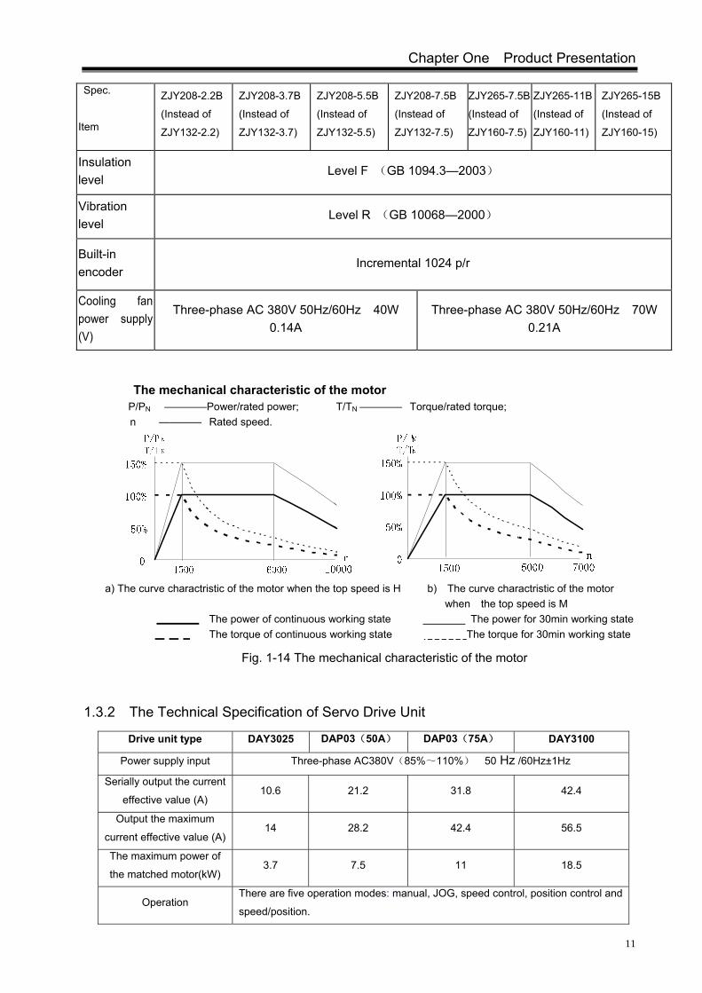
The mechanical characteristic of the motor P/PN ————Power/rated power; T/TN ———— Torque/rated torque; n ———— Rated speed.
a) The curve charactristic of the motor when the top speed is H b) The curve charactristic of the motor
when the top speed is M The power of continuous working state The power for 30min working state The torque of continuous working state The torque for 30min working state
Fig. 1-14 The mechanical characteristic of the motor
1.3.2 The Technical Specification of Servo Drive Unit
Drive unit type DAY3025 DAP03(50A) DAP03(75A) DAY3100
Power supply input Three-phase AC380V(85%~110%) 50 Hz /60Hz±1Hz
Serially output the current
effective value (A) 10.6 21.2 31.8 42.4
Output the maximum
current effective value (A) 14 28.2 42.4 56.5
The maximum power of
the matched motor(kW) 3.7 7.5 11 18.5
Operation There are five operation modes: manual, JOG, speed control, position control and
speed/position.

DAP、DAY Series Spindle Servo Drive Unit User Manual
12
Torque speed governing
ratio 1000:1(The matched motor speed range is 1.5r/min~1500r/min).
Constant power speed
governing ratio 4:1(The matched motor speed range is 1500r/min~6000r/min).
The accuracy of steady
speed
Rated speed × 0.1%.
Analog command input mode :①-10V~+10V; 0V② ~+10V.
Speed control working
Speed command electronic gear function: Analog command multiple coefficient:
1~32767;
Analog command frequency-division
coefficient: 1~32767.
Motor encoder feedback
input
Incremental rotation encoder feedback signal, resolution 128p/r~8000p/r can be
set, the A/B/Z difference signal.
Position command input mode: Pulse + direction;①
CCW pulse /CW pulse;②
A/B③ phases orthogonal pulse.
Position control working Position command electrical gear function: Pulse command multiple coefficient:
1~32767;
Pulse command frequency-division
coefficient: 1~32767.
Orientation function
8 orientation points can be set on the motor encoder or on the 2nd position
encoder, which is selected by the external contact point signal and started the
motor (spindle) orientation; the orientation angle offset is
≤ encoder of number line180° .
The 2nd position encoder
feedback input
Incremental rotation encoder feedback signal, resolution 128p/r~8000p/r can be
set, A/B/Z difference signal.
Position feedback outputThe signal of the motor encoder or the spindle encoder is output in 1:1, A/B/Z
difference signal.
Control input signal
There are 11 input points, such as servo enabling, CCW start, CW start,
orientation start, the 2nd speed gain selection, orientation (speed) selection, zero
speed clamping, the alarm resetting and speed/position shift.
Control output signal 7 output points: Ready, zero speed output, position/speed arrival, positioning
completion, alarm output, speed/position state and position feedback Z pulse.
Protective function
Protection functions, such as overvoltage, undervoltage, phase lacking,
overspeed, overcurrent, overload, overheating, encoder abnormity and position
out-of-tolerance, etc.
Display function
6-bit LED, software and hardware versions, working, current speed, speed
command, current encoder position, current, I/O state, DC bus voltage, alarm
codes, parameters and the like, which can be displayed.
Operation function 5 keys can be operated for displaying the content, modifying the parameter and
administration.
Safety level IP20

Chapter One Product Presentation
13
1.4 An Instruction of Placing an Order
1.4.1 The Specification for the Item
For example, the types of adapted ZJY spindle motor are shown below:
Type Spindle motor parameter Drive unit power module
DAY3025-022-ZJY208-2.2BH-B5/B3 14Nm, 1500r/min, 9.3A 25A module
DAY3025-037-ZJY208-3.7BH-B5 24Nm, 1500r/min, 8.9A 25A module
DAP03-055-ZJY208-5.5BH-B5 35Nm, 1500r/min, 13.7A 50A module
DAP03-075-ZJY208-7.5BM-B5 48Nm, 1500r/min, 18.4A 50A module
DAP03-075-ZJY265-7.5BM-B5/B3 49Nm, 1500r/min, 18A 50A module
DAP03-110-ZJY265-11BM-B5/B3 72Nm, 1500r/min, 26A 75A module
DAY3100-150-ZJY265-15BM-B5/B3 98Nm, 1500r/min, 35A 100A module
1. It is very essential to choose a motor in terms of the matched type provided by Guangzhou CNC Sale Department. Please write down the configuration motor type while you place an order, so that the relative parameter value of factory drive unit can be set;
2. It is very important to touch contact with the company professionals in time if the user selects a self-configuration motor by himself or herself; otherwise, we can not give a promise that the spindle drive unit can drives the motor normally.
DAP、DAY Series Spindle Servo Drive Unit User Manual
14
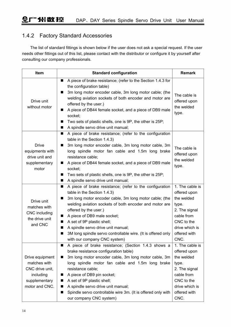
1.4.2 Factory Standard Accessories
The list of standard fittings is shown below if the user does not ask a special request. If the user needs other fittings out of this list, please contact with the distributor or configure it by yourself after consulting our company professionals.
Item Standard configuration Remark
Drive unit without motor
A piece of brake resistance; (refer to the Section 1.4.3 for the configuration table)
3m long motor encoder cable, 3m long motor cable; (the welding aviation sockets of both encoder and motor are offered by the user.)
A piece of DB44 female socket, and a piece of DB9 male socket;
Two sets of plastic shells, one is 9P, the other is 25P; A spindle servo drive unit manual;
The cable is offered upon the welded type.
Drive equipments with
drive unit and supplementary
motor
A piece of brake resistance; (refer to the configuration table in the Section 1.4.3)
3m long motor encoder cable, 3m long motor cable, 3m long spindle motor fan cable and 1.5m long brake resistance cable;
A piece of DB44 female socket, and a piece of DB9 male socket;
Two sets of plastic shells, one is 9P, the other is 25P; A spindle servo drive unit manual;
The cable is offered upon the welded type.
Drive unit matches with CNC including the drive unit
and CNC
A piece of brake resistance; (refer to the configuration table in the Section 1.4.3)
3m long motor encoder cable, 3m long motor cable; (the welding aviation sockets of both encoder and motor are offered by the user.)
A piece of DB9 male socket; A set of 9P plastic shell; A spindle servo drive unit manual; 3M long spindle servo controllable wire. (It is offered only
with our company CNC system)
1. The cable is offered upon the welded type. 2. The signal cable from CNC to the drive which is offered with CNC.
Drive equipment matches with
CNC drive unit, including
supplementary motor and CNC.
A piece of brake resistance; (Section 1.4.3 shows a brake resistance configuration table)
3m long motor encoder cable, 3m long motor cable, 3m long spindle motor fan cable and 1.5m long brake resistance cable;
A piece of DB9 pin socket; A set of 9P plastic shell; A spindle servo drive unit manual; Spindle servo controllable wire 3m. (It is offered only with
our company CNC system)
1. The cable is offered upon the welded type. 2. The signal cable from CNC to the drive which is offered with CNC.

Chapter One Product Presentation
15
1.4.3 Brake Resistance
① The external aluminum shell brake resistance configuration table of servo spindle
Big or medium inertial application (such as the lathe)
Small inertia application (such as milling machine)
Spindle motor rated
output power(kW)
Matched spindle
drive unit type Spec.
Spec. (finished product identification
code) Spec.
Item (finished product identification code)
2.2 DAY3025 500W/47Ω RXLG500W47RJJ 500W/47Ω RXLG500W47RJJ
3.7 DAY3025 800W/47Ω RXLG800W47RJJ 500W/47Ω RXLG500W47RJJ
5.5 DAP03 1200W/30Ω RXLG1200W30RJJ 800W/47Ω RXLG800W47RJJ
7.5 DAP03 1500W/30Ω RXLG1500W30RJJ 1200W/30Ω RXLG1200W30RJJ
11 DAP03
(1000W/56Ω)//2* RXLG1000W56RJJ 1500W/30Ω RXLG1500W30RJJ
15 DAY3100
(1500W/30Ω)//2* RXLG1500W30RJJ (1200W/30Ω)//2* RXLG1200W30RJJ
Note: *:“//2” means that each drive unit is needed to connect two brake resistances of the same type in parallel, the leading wires are respectively connected in parallel, which is installed on the drive unit separately after the pressure welding is performed.
② The explanation of the brake resistance types
RXLG 1200W 30R J JWiring M:terminal,J:Leading wire
The accuracy of resistance valueK:±10%, J:±5%Brake resistance value: 30R means 30Ω
Brake resistance power:100W~2000W
Product code
③ The appearance of the brake resistance
④ The dimension of the brake resistance

DAP、DAY Series Spindle Servo Drive Unit User Manual
16
B
Fig.1-19-1 Installation aperture 5.5 mm
A
D
C
B
C
Fig.1-19-2 Installation aperture 5.5mm
A
D
E
Dimension (mm) Wiring (mm2)
Product code
Brake resistance power (W)
Figure A B C D E
The length of leading-wire
(mm) Terminal
RXLG 500 335 323 60 30 / 2.5 1000 M5
RXLG 800
Fig. 1-19-1 400 388 61 59 / 2.5 1000 M5
RXLG 1000 400 388 50 107 30 2.5 1000 M5
RXLG 1200 450 438 50 107 30 2.5 1000 M5
RXLG 1500
Fig. 1-19-2
485 473 50 107 30 2.5 1000 M5
⑤ Brake resistance installation interval
>150mm >150mm
>100mm
1. Never attempt to touch the brake resistance surface which may be caused high pressure and temperature when the drive unit is ON or being operated!
2. It is necessary to install the separative hood!
3. The surface temperature of the external aluminum shell brake resistance may reduce slowly after the drive unit is OFF! The surface temperature of the brake resistance is reduced to the room temperature and after the drive unit is OFF for 10 minutes which can be felt when the maintenance and checking can be performed.

Chapter Two Installation
17
CHAPTER TWO INSTALLATION
2.1 Spindle Servo Motor
2.1.1 The Installation Dimension of the Spindle Motor
Fig. 2-1 Flange installation type (B5)
Fig. 2-2 Foot installation type (B3)
Table 2-1 Installation dimension table (Unit: mm)
Motor type
Item
ZJY208-2.2B (Instead of ZJY132-2.2)
ZJY208-3.7B (Instead of ZJY132-3.7)
ZJY208-5.5B(Instead of ZJY132-5.5)
ZJY208-7.5B(Instead of ZJY132-7.5)
ZJY265-7.5B (Instead of ZJY160-7.5)
ZJY265-11B (Instead of ZJY160-11)
ZJY265-15B(Instead of ZJY160-15)
A 208 208 208 208 265 265 265
B 104 104 104 104 132 132 132
C 188 188 188 188 216 216 216
D 215 215 215 215 265 265 265
E 60 60 80 80 110 110 110
F 363 413 468 523 443 488 533
Figure dimension (see the
figure)
G 187 237 292 347 260 305 350

DAP、DAY Series Spindle Servo Drive Unit User Manual
18
H 180h7 180h7 180h7 180h7 230h7 230h7 230h7
I 15 15 15 15 15 15 15
J 28h6 28h6 38h6 38h6 48h6 48h6 48h6
K 272 272 272 272 300 300 300
L 106 106 106 106 135 135 135
N 180 180 180 180 230 230 230
P 40 40 40 40 40 40 40
Q 160 210 265 320 225 270 315
Z 12 12 12 12 15 15 15
2.1.2 The Installation of the Spindle Motor
The installation, storage and transportation circumstance of the spindle motor:
Item Index
Temperature 0~40
Storage and transportation temperature -40~55
Humidity 30%~95% (non-condensing)
Storage and transportation humidity ≤95%(40)
Atmosphere circumstance The control cabinet should be free of the
caustic gas, flammable gas, oil mist and dust
Altitude Below the altitude 1000m
Reserve enough space above the lid of the spindle motor terminal box or near the wiring terminal
for disassembling the screws and wiring. When the install conditions can not offer a space to the terminal box, contact the agency freely. Never attempt to change the structure of motor privately.
Fig. 2-3
Chapter Two Installation
19
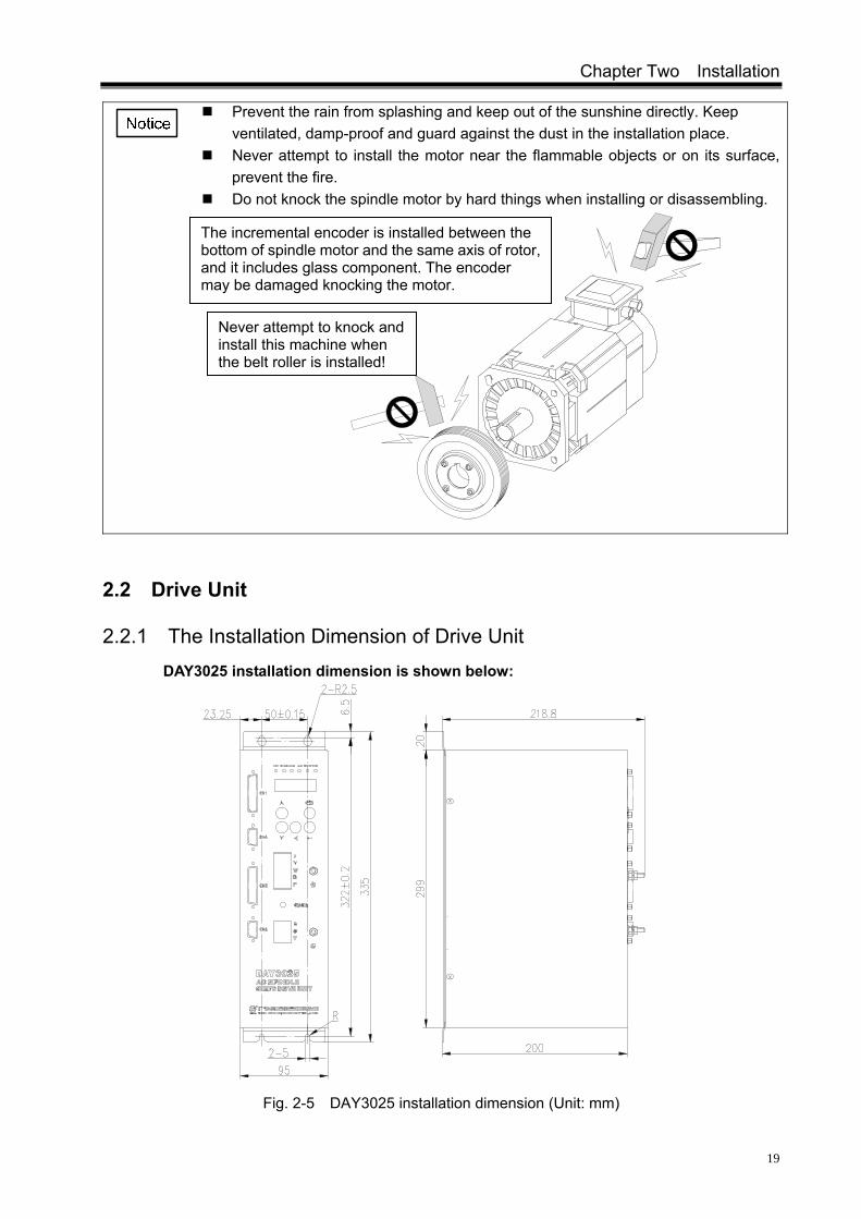
Prevent the rain from splashing and keep out of the sunshine directly. Keep ventilated, damp-proof and guard against the dust in the installation place.
Never attempt to install the motor near the flammable objects or on its surface, prevent the fire.
Do not knock the spindle motor by hard things when installing or disassembling.
2.2 Drive Unit
2.2.1 The Installation Dimension of Drive Unit DAY3025 installation dimension is shown below:
Fig. 2-5 DAY3025 installation dimension (Unit: mm)
The incremental encoder is installed between the bottom of spindle motor and the same axis of rotor, and it includes glass component. The encoder may be damaged knocking the motor.
Never attempt to knock and install this machine when the belt roller is installed!

DAP、DAY Series Spindle Servo Drive Unit User Manual
20
DAP03 installation dimension is shown below:
POWER
RUN
LCCW
OREND
LCW
PAR/SAR
CN1CN3 CN2
Fig. 2-6 DAP03 installation dimension figure (Unit: mm)
DAY3100 installation dimension is shown below:
R
CN1
POWER
CHARGE
P
B
W
V
U
T
S
R
RUN
CN2
CN3
SAR
LCWLCCW PAROREND
Fig. 2-7 DAY3100 installation dimension (Unit: mm)
R

Chapter Two Installation
21
2.2.2 The Installation of the Drive Unit
Drive unit installation condition directly affects the function and the operation life-span. It is very essential to install the drive unit into the control cabinet in terms of the following notices.
Prevent the rain from splashing and keep out of the sunshine directly. The drive unit should be installed into the electric cabinet for preventing the
dust, corrosive gas, as well as the electric conductions and inflammable objects.
Keep ventilated, damp-proof and guard against the dust in the installation place.
Never attempt to install it near the flammable objects or on its surface, prevent the fire.
The installation place should be convenient for maintaining, checking. Never attempt to install other electric equipments above the drive unit to
prevent the heat airflow sent out from the drive unit causing a damage for the other electric equipment, and the heat dissipation of the drive unit itself may be affected simultaneously.
The control cabinet should have the following conditions:
The drive unit is adopted the foot installation type, the installation direction should be erected on
its surface. For heat dissipation, the face of the drive unit is front and the top is upward during installation.
Item Index
Temperature 0~40
Warehousing and transportation temperature
-40~55
Humidity 30%~95%(No condensing)
Warehousing and transportation humidity
≤95%(40)
Atmosphere condition The control cabinet should be free of the corrosive gas,
flammable gas, oil mist and dust.
Altitude Below altitude1000m
Vibration ≤0.6G(5.9m/s2)
Air pressure 86kPa~106kPa
The protection level of installation condition
IP43

DAP、DAY Series Spindle Servo Drive Unit User Manual
22
Fig. 2-8 The installation interval of DAY3025
Fig. 2-9 The installation interval of DAP03 drive unit

Chapter Two Installation
23
120mm
150 mmUp
Down
CN1
CN2
CN3
LCCWRUN POWER ORENDLCW PAR
SAR
B
V
P
W
U
T
S
R
150 mm
120 mm
150 mm
Cabinet
Front
Fig. 2-10 The installation interval of DAY3100 drive unit

DAP、DAY Series Spindle Servo Drive Unit User Manual
24
CHAPTER THREE CONNECTION
It is very necessary to check the following notices, and the user should perform the connection in terms of the requirements for safety.
The wiring should be performed correctly by the professional and connected based on the relative specification.
The wiring and check should be performed after the drive unit is turned off for 5min by confirming the voltage of main circuit is safe with the multimeter; otherwise, it may be electric shock hazard.
Confirm the drive unit and spindle servo motor grounding.
The cable can not be damaged by sharp object and strongly drew; otherwise, the electric shock or bad circuit connection may occur.
Do not put the main circuit wiring and the signal wiring through a same tube or mix them. When the wiring is performed, the main circuit wiring should be divided from the signal wiring more than 30cm or crossed for preventing the strong circuit caused an interruption to the signal wiring, and then the drive unit can not be operated normally.
Do not turn ON/OFF frequently because there is the high capacitance within the drive unit and the heavy charging current may occur after the power is turned on; otherwise, the internal main circuit parts capacity may reduce due to the power is turned on/off frequently, so, the shifting between ON/OFF should be performed up to 3 minutes.
The equipments, such as the power capacitance, surge absorber and wireless noise filter, which can not be installed between the drive unit output side and spindle servo motor.
The main circuit wiring and signal wiring should not be closed to the heat sink, brake resistance and motor, so that the insulativity is reduced due to the heat.
The terminal protection lid should be covered to avoid electric shock after the main circuit connection is performed.
U
V
W
PE
Motor
M
Drive unit ~

Chapter Three Connection
25
3.1 The Connection of Peripheral Equipment
Using the spindle servo drive unit should be adapted some peripheral equipments (devices in the virtual frame in the following figure), the correct peripheral equipment makes the steady operation of the drive unit, otherwise, the service life may reduce, even the drive unit may be damaged.
Fig. 3-2 The connection of DAY3025 peripheral equipments

DAP、DAY Series Spindle Servo Drive Unit User Manual
26
Refer to the appendix B for the selection of circuit breaker, interference filter, reactor and AC contactor
UVWR S T
PE PE
P B
Dynamic brake resistance
Circuit breaker(MCCB)
Interference filter(FIL)
Reactor
Power grounding
TSRThree-phaseAC380V
It is used for protecting the power, the circuit is cut off immediately when the overcurrent may issue.
It is used for suppressing the electromagnetic interference where from the power terminal
It is used for improving the power factor and filtering the high harmonic interference, it makes the motor operation more steady.
The brake resistance becomes heat because discharge. Never attempt to touch the surface because it is high temperature against burn
Motor encoder check signal connection CN2
The 2nd
position encoder check signal connection CN3
Signal control connectionCN1
Control system
CNC system
Chip systemOperation control PLC
systemPC+Operation control
card
AC contactor
The AC contactor can open/close the power of drive unit by the ESP switch to improve the security of electric circuit.
Motor power cable
Motor fan cable
The 2nd position encoder check signal can be achieved the accurate orientation of spindle
Fig. 3-3 The connection of DAP03 peripheral equipments

Chapter Three Connection
27
Refer to the appendix B for the selection of circuit breaker, interference filter, reactor and AC contactor
Fig. 3-4 The connection of DAY3100 peripheral equipments Refer to the appendix B of breaker, interference filtering, reactor and AC contractor
DAP、DAY Series Spindle Servo Drive Unit User Manual
28
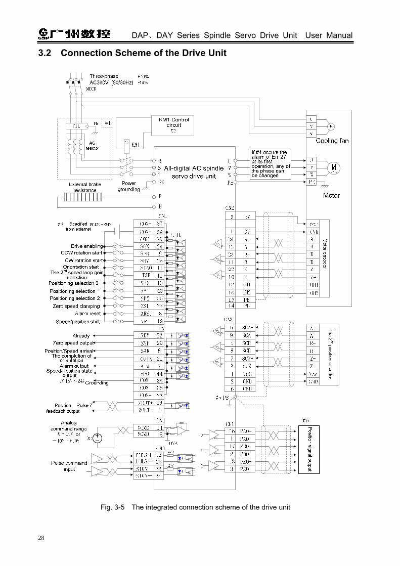
3.2 Connection Scheme of the Drive Unit
Fig. 3-5 The integrated connection scheme of the drive unit

Chapter Three Connection
29
#1: The components in the virtual frame are optional items, when the on-site circumstance can not guarantee the drive unit work normally, the user can refer to the self-configuration of <Appendix B: the selection of the peripheral equipment> for the self-configuration.
#2: As for the AC contactor control, it is recommended to use the power switches on the system operation panel in machine tool:
Fig. 3-6
#3: The least power of external given DC 15V~24V switch power should not be less than 35W. #4: Note that not every drive units corresponded with the U, V and W when the motor is
connected with that of the U, V and W. When the Err-27 occurs when firstly operating the motor, the phase sequence of user motor cable is incorrect, which is not indicated the drive unit is malfunction.
#5: Three metal shells, CN1, CN2 and CN3 interfaces should be connected with the PE of the drive unit, which is regarded as the welding point of the shielding cable.
#6: Whether the position signal output is from the motor encoder signal or the 2nd position input signal which is set by the parameter PA69.
As for the signal cable, encoder (PG) feedback, it is very important to use the stranded conductor wire and multicore stranded integrative shielded cable.
The analog command input cable is up to 3m long for the wiring length; if the position command is difference, the cable is up to 10m long, and the wiring of the single collector is maximum 2m long, PG feedback cable is maximum 30m long and the other I/O signal cable is up to 20m long.
3.3 The Connection of Main Circuits
The main circuit terminal explanation of the drive unit: Terminal
mark Name Explanation
R、S、T AC power input terminal
Power input 3-phase AC380V(85%~110%)
50Hz/60Hz±1Hz.
U、V、W 3-phase AC output terminal
It is connected with the terminals of motor 3-phase winding U, V and W.
P、B Brake resistance terminal
The brake resistance is used for dynamic brake, and the drive unit can be operated normally until the external brake resistance is performed.
PE Protection grounding terminal
It is connected with the power grounding and motor grounding, and the protective grounding resistance should be less than 10Ω.

DAP、DAY Series Spindle Servo Drive Unit User Manual
30
Encoder socket
U V W
U V W
Motor wiring socket
Motor wiring socket
Cable fixed position
Grounding screw
The specification of ZJY spindle servo motor terminal box: The three-phase winding U, V and W of motor and the shell (grounding) are leaded out by the
cable fixed-head; its position inside the wiring box is as below. U, V, W and shell (grounding) are separately connected the main circuit terminals U, V, W and PE of the drive unit. The air direction of the cooling fan blows from the shaft extended terminal to the end of the fan, and the three-phase AC380V is connected externally.
Fig. 3-7
The power output U, V and W of drive unit may not inconsistent with that of the
phase sequence of U, V and W of the spindle motor when the drive unit is configurated with different spindle servo motors. Generally, if the motor rotates at some constant speed instead of controlling till the No. Err-27 alarm occurs after the motor is enabled, which is means that the phase sequences are not inconsistent. Shifting any of two phases among the U, V and W which can be used after the power is turned off for 5min.
Operation motor
Normal motor operation Correct
connection
The fixed motor speed is not controlled, alarm occurs after 10 senconds
Changing any of the phases, as the
left figure.
U
V
W
U
V
W
Motor
M
U
V
W
U
V
W
Motor
M

Chapter Three Connection
31
It is recommended that the used cable and wiring terminal of the servo drive unit input (R, S and T) and output (U, V and W) should be confirmed in the following list.
Cable path (mm2)
Applicable powerTerminal screw
dimension R,S,T U,V,W PE P、B
DAY3025-022 M5 2.5 2.5 2.5 2.5
DAY3025-037 M5 2.5 2.5 2.5 2.5
DAP03-055 M5 2.5 2.5 2.5 2.5
DAP03-075 M5 4 4 4 4
DAP03-110 M5 4 4 4 4
DAY3100-150 M5 6 6 6 4

DAP、DAY Series Spindle Servo Drive Unit User Manual
32
3.4 The Connection of Control Signals
3.4.1 CN1 Pin Definition
Drive unit control cable interface CN1 is 44-male socket, the connector for making the connection wire should be 44-female socket (G3150-44FBNS1X1 type offers by WIESON Company). And the pin definition is as following:
Fig. 3-9 CN1 pin definition
The pins are shared with the same name which have been performed the short circuit together inside the PCB as the following figure.

Chapter Three Connection
33
I/O signal list P: Position control S: Speed control S/P: Speed/position shift
Type Signal input
name Terminal number
Function Referen
ce
COM+ 37、38、
39 Public terminal of the input point, the input terminal which is connected the external DC power 15V~24V.
3.4.2
COM- 23、35、
36 Public terminal of the output point, connect the external DC 15V~24V power grounding
3.4.2
SON 24 Servo enable signal 3.4.2
P、S
ARST 8 Alarm resetting signal 3.4.2
VCMD+ VCMD-
14 15
Analog voltage command input 3.4.2
0VA 29、30 Internal analog grounding \
SFR 9 It is CCW rotation start input when PA46=1; It is drive enable allowance signal when PA46=0.
5.2.1
SRV 25 It is CW rotation start input when PA46=1; It is disabled when PA46=0.
5.2.1
The speed selection 0 is performed when it is used for multiple speed function selection;
5.2.2 SP0 10
The orientation selection 0 is performed when it is used for orientation position function selection.
6.6.1
The speed selection 1 is performed when it is used for multiple speed function selection;
5.2.2 SP1 40
The orientation selection 1 is performed when the positioning function is selected.
6.6.1
The speed selection 2 is performed when it is used for multiple block speed function selection;
5.2.2 SP2 26
The positioning selection 2 is performed when the positioning function is selected.
6.6.1
ZSL 27 Zero clamping signal 6.6.4
S
STAO 11 Orientation start signal 6.6.1
PULS+ PULS-
42 28
P SIGN+ SIGN-
33 34
Positioning command pulse input. Pulse + direction CCW pulse + CW pulse; A/B phase pulse.
3.4.2
P、S TAP 41 The 2nd gain selection for speed loop 6.1.2
S/P VP 12 Speed/position shift (The function is disabled when PA4=5). 5.4
ALM 7 Alarm output signal 3.4.3
RDY 22 Ready signal 3.4.3
SECT 6 To be developed \
ZOUT+ ZOUT-
19 4
Position feedback output, phase Z signal integral polar output.
3.4.3
PAO+ PAO-
16 1
PBO+ PBO-
17 2
P、S
PZO+ PZO-
18 3
Position feedback output signal Refer to the relative parameters PA69~PA71.
3.4.3
6.3

DAP、DAY Series Spindle Servo Drive Unit User Manual
34
Type Signal output name
Terminal number
Function Referen
ce
ZSP 20 Zero speed output signal 3.4.3 S
COIN 21 The completion output signal of orientation 6.6.1
The position arrival output signal is performed in position control mode.
6.5.2 P、S PAR/SAR 5
The speed arrival output signal is performed in speed control mode.
6.6.3
S/P VPO 44 Speed/position status output (It is valid when PA4=5). 5.4
3.4.2 Signal Input Explanation
① Analog command input: VCMD+(CN1-14)/ VCMD-(CN1-15 is speed command input terminal, the maximum DC voltage
signal is up to 10V, and the terminal input resistance is 15KΩ.
Fig. 3-10
Fig. 3-11
Explanation: It is recommended to use the twisted pair signal cable, the shielded wiring method is recommended that it not always to be used.
② Position command input:
PULS+ PULS-
CN1-42 CN1-28
SIGN+ SIGN-
CN1-33 CN1-34

Chapter Three Connection
35
The user can use both the difference drive connection and the single-ended drive connection, see the following figure.
The difference drive connection
4.7K
4.7K
Instruction control unit
Fig. 3-12 The difference drive connection
The single-terminal drive connection
a) NPN type
4.7K
4.7K
b) PNP type
Fig. 3-13 The single-terminal drive connection

DAP、DAY Series Spindle Servo Drive Unit User Manual
36
1. It is recommended to adopt the method of the difference drive for improving against the anti-interference ability; In the mode of the difference drive, it is recommended to use AM26LS31, MC3487 or similar to RS422 drive chip for the interface circuit;
2. The operation frequency may decrease by using the single-ended drive mode, the circuit is input in terms of the pulse amount, and the drive current is 10 mA~15mA. The maximum voltage 25V in external power is restricted, and the resistance R is confirmed. The empirical data are: VCC=24V, R=1.3 kΩ~2kΩ; VCC=12V, R=510Ω~820Ω; VCC=5V, R=0Ω.
The acceptable position command input modes are divided into three sections, and it is
determined by parameter PA14, the arrow indicates counting edge, as shown below:
a. Pulse + direction: interface input time sequence figure (The maximum pulse frequency is 500kHz) th
tltrh trlts ts
tck
trh trl
90%
90%
10%
10%
CW CWCCW
PULS
SIGN
Fig. 3-14
b. CCW /CW pulse input interface time sequence figure (The maximum pulse frequency is 500kHz)
Fig. 3-15
Pulse command mode
Pulse direction
CW pulse
CCW pulse
Phase B pulse
Phase A pulse
CCW CW
PULS
SIGN
PULS
SIGN
PULS
SIGN
Parameter setting value
PA14=0
Command pulse+direction
PA14=1
CCW pulse+CW pulse
PA14=2
Two-phase pulse command

Chapter Three Connection
37
c. The interface time sequence figure of two-phase command pulse input (The maximum pulse frequency is 125kHz)
Fig. 3-16
The pulse input time sequence parameters are shown below:
Parameter tck th tl trh trl ts tqck tqh tql tqrh tqrl tqs
Difference drive input(μs)
>2 >1 >1 <0.2 <0.2 >1 >8 >4 >4 <0.2 <0.2 >1
Single-ended drive input(μs)
>5 >2.5 >2.5 <0.3 <0.3 >2.5 >10 >5 >5 <0.3 <0.3 >2.5
③ Input point of switching value
Two examples of wiring are shown below, INX indicates input points: (SON, ARST, SFR, SRV, SP0, SP1, SP2, ZSL, STAO, TAP and VP).
The example of external switch amount
The example of external photocoupler
Fig. 3-17

DAP、DAY Series Spindle Servo Drive Unit User Manual
38
The servo unit is without 24V power output, it is neceesary to adapt 24V power outside. The specification: DC15V~24V, and above 100mA. It is recommended to use a same power with the output circuit.
When INX is connected with 0V, input an optical CO Conduction, and the signal is ON, the input is then enabled. Check the monitoring window to judge, if the input point is ON, the corresponding nixie tube may light up; if the input point is cut off and the signal is OFF, the nixie tube is OFF. This monitoring window can be debugged, checked and repaired for the drive unit control signal.
Fig. 3-18 ④ The details of general input signals:
COM+(CN1-37/38/39)is input position common terminal, and COM-(CN1-23/35/36)is output position common terminal, which are the input terminals of the external given DC power 15V~24V, the input current should be less than or equal to 100mA.
The power polar can not be connected reversely, otherwise, the drive unit can not be operated normally.
When SON (CN1-24) is ON, the servo enabling is started to check the monitor
window , and the is displayed.
Relative
parameter Significance Unit Default Applicable
PA33
PA33=1, forced enabling (do not check the SON (CN1-24) signal); PA33=0, the enabling signal is specified by SON (CN1-24).
0 P,S
① The position mode, manual, JOG and internal digital commands are enabled in the mode of
speed:
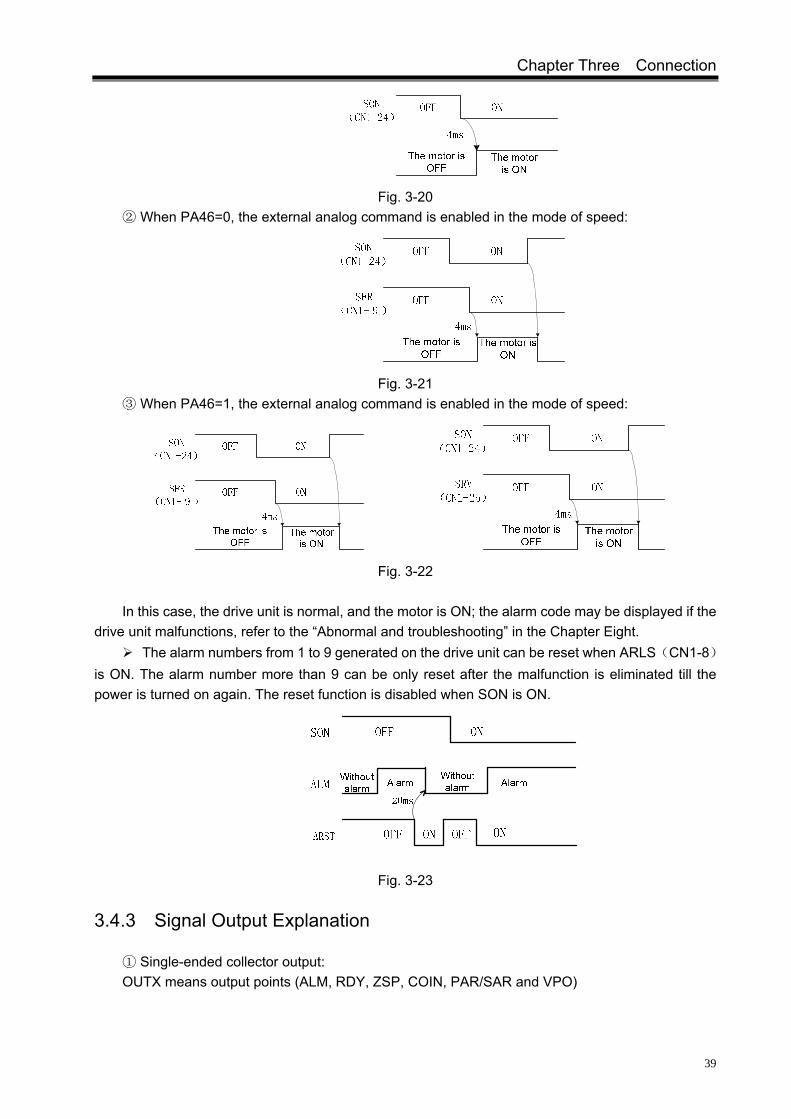
Chapter Three Connection
39
Fig. 3-20 ② When PA46=0, the external analog command is enabled in the mode of speed:
Fig. 3-21 ③ When PA46=1, the external analog command is enabled in the mode of speed:
Fig. 3-22
In this case, the drive unit is normal, and the motor is ON; the alarm code may be displayed if the drive unit malfunctions, refer to the “Abnormal and troubleshooting” in the Chapter Eight.
The alarm numbers from 1 to 9 generated on the drive unit can be reset when ARLS(CN1-8)is ON. The alarm number more than 9 can be only reset after the malfunction is eliminated till the power is turned on again. The reset function is disabled when SON is ON.
Fig. 3-23
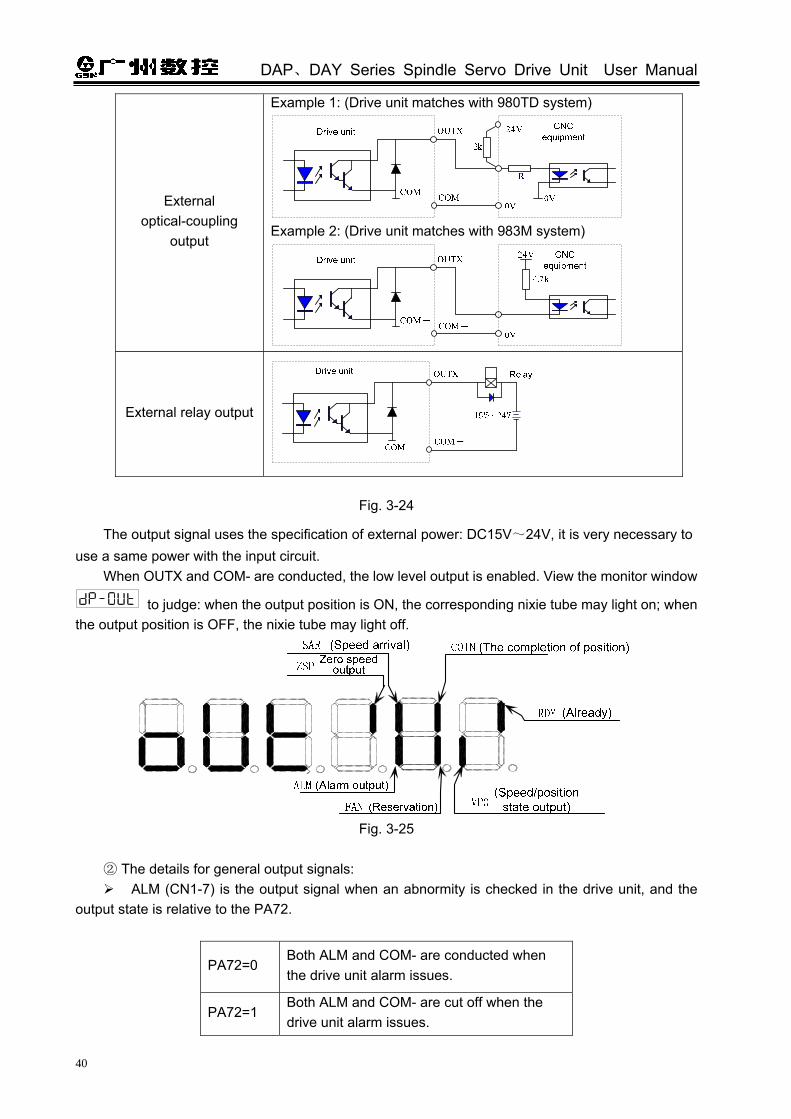
3.4.3 Signal Output Explanation
① Single-ended collector output: OUTX means output points (ALM, RDY, ZSP, COIN, PAR/SAR and VPO)
DAP、DAY Series Spindle Servo Drive Unit User Manual
40
External optical-coupling
output
Example 1: (Drive unit matches with 980TD system)
Example 2: (Drive unit matches with 983M system)
External relay output
Fig. 3-24
The output signal uses the specification of external power: DC15V~24V, it is very necessary to use a same power with the input circuit.
When OUTX and COM- are conducted, the low level output is enabled. View the monitor window
to judge: when the output position is ON, the corresponding nixie tube may light on; when the output position is OFF, the nixie tube may light off.
Fig. 3-25
② The details for general output signals:
ALM (CN1-7) is the output signal when an abnormity is checked in the drive unit, and the output state is relative to the PA72.
PA72=0 Both ALM and COM- are conducted when the drive unit alarm issues.
PA72=1 Both ALM and COM- are cut off when the drive unit alarm issues.

Chapter Three Connection
41
Fig. 3-26
RDY (CN1-22) drive unit ready signal is conducted with COM- when the motor is excited with power on.
Power
Alarm output (ALM)
Drive enabling(SON)
Already(RDY) 4ms
2ms
Without alarm
OFF OFFON
OFF ON OFF
Alarm
ON OFF
ON
ONOFF
Fig. 3-27
ZSP (CN1-20) zero speed output is conducted with COM- when the motor speed is less than the setting value of PA32.
Fig. 3-28
③ Double-ended collector output: ZOUT+(CN1-19)/ZOUT-(CN1-4) position feedback output Z pulse signal, that is a one-turn
signal of the encoder. When PA69=0, the output is a motor encoder Z pulse signal which is input by CN2 When PA69=1, the output is a Z pulse signal from the 2nd position feedback signal which is input
by CN3.

DAP、DAY Series Spindle Servo Drive Unit User Manual
42
External C
NC
system
External high-speed optical coupling
Drive unit
DC5V~24V
ZOUT+
ZOUT-
High-speed optical coupling
Fig. 3-29
1. The output is open-collector, the maximum load current is 100mA, and the external DC is up to 25V. The servo unit may damage if it exceeds the requirements or the output is connected with the power directly.
2. If the load is inductive, the inverse parallel and fly-wheel diode should be connected at the terminals of the load. The servo unit may get damaged if the fly-wheel diode is connected reversely.
3. It is recommended to use a same power supply with the input circuit.
④ Difference output: The position output signals, such as PAO+/PAO-, PBO+/PBO- and PZO+/PZO-, are adopted the
difference output. (Refer to the position signal output in the Section 6.3). The position signal input from CN2 or CN3 is pulse signal of incremental encoder feedback.
For example: TAMAGAWA incremental encoder output signal type:
Fig. 3-30
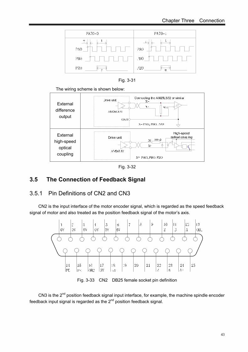
When the wave of the position output signal is PA71=1, the output is performed based on the wave of the position input signal. The wave output is also affected by the reverse output signal of PA70:
Chapter Three Connection
43
Fig. 3-31
The wiring scheme is shown below:
External difference
output
External high-speed
optical coupling
Fig. 3-32
3.5 The Connection of Feedback Signal
3.5.1 Pin Definitions of CN2 and CN3
CN2 is the input interface of the motor encoder signal, which is regarded as the speed feedback signal of motor and also treated as the position feedback signal of the motor’s axis.
Fig. 3-33 CN2 DB25 female socket pin definition
CN3 is the 2nd position feedback signal input interface, for example, the machine spindle encoder
feedback input signal is regarded as the 2nd position feedback signal.

DAP、DAY Series Spindle Servo Drive Unit User Manual
44
Fig. 3-34 CN3 DB9 female socket interface pin definition
3.5.2 The Pin Specifications both CN2 and CN3
The incremental encoder signal wiring is difference drive connection, and its wiring scheme is shown below:
Drive unitEncoderX+
X-
X=A、B、Z、SCA、SCB、SCZ
120ΩAM26LS32
Fig. 3-35
The OH1(CN2-13) / OH2(CN2-16) in the CN2 interface is used for connecting the over-heat check parts inside the spindle servo motor, so that the drive unit is with the function of motor over-heat protection. Thereof, the OH2 (CN2-16) has been connected inside the 5V grounding.
Fig. 3-36
If the over-heat check parts (OH1/OH2 does not connect) are not created within the motor, the Err-5 alarm of drive unit may occur. In this case, the OH1(CN2-13)and OH2(CN2-16)should be connected in short circuit or the PA73 is set to 1, and then the motor over-heat alarm is shielded.
Relative
parameter Name Unit
Parameter range
Default value
Applicable
Motor over-heat alarm shielding
0~1 0 P,S
PA73 The motor over-heat alarm is enabled when PA73 is equal to 0; The motor over-heat alarm is shielded when PA73 is equal to 1.

Chapter Three Connection
45
The following figure is the wiring diagram of GSK AC spindle servo motor encoder. If users want to use motors from other manufactures or make the feedback signal by yourself, it is necessary to refer to the following figure.
ZJY S
pindle servo motor encoder output term
inal
CN
2 spindle servo drive unit
Fig. 3-37 GSK spindle servo motor encoder wiring scheme
The definition of ZJY serial spindle servo motor encoder signal interface is as shown below:
Encoder pin Shell (PE) VCC GND A A- B B- Z Z-
Socket pin number
1 2 3 4 7 5 8 6 9
Encoder signal wiring industrial socket (aviation socket) figure is shown below:
Fig. 3-38
Socket (Weld side)
12
35
610
1113
1415

DAP、DAY Series Spindle Servo Drive Unit User Manual
46
Fig. 3-39 TAMAGAWA TS5308N512 encoder is regarded as a wiring example for
connecting the 2nd position encoder and CN3
1. The motor power cable and motor encoder feedback signal cable should be within 20m, and their distance should be more than 30cm. Two cables can not be used a same tube or bound together.
2. The signal cable should be adopted the stranded shielding cable, the line section is 0.15mm2~0.20mm2, and the shielding layer should be connected with PE terminal.
3.6 The Wiring Example in Different Workings
3.6.1 Wiring in Speed Mode
A. The drive unit works on the analog command speed mode when PA4=1 and PA22=1 Refer to the Section 5.2.12 of Chapter Five for debugging operation in this mode.
Spindle servo drive unit
TAM
AG
AW
A encoder output term
inal

Chapter Three Connection
47
3839
*SON 24*SFR 9
*SRV 25STAO 11
TAP 41
SP0
SP1 40
SP2 26
External givenDC15V~24V
Drive enabling
Orientation start
Alarm reset
ZSP20
RDY22
Zero speed outputAlready
Position/speed arrival
ZSL 27Zero speed clamping
10
SAR
COIN
5
21
16
1
2
18
3
The 2nd speed loop gain selection
Positioning selection 0
8ARST
Position completion
7 ALM Alarm output*COM+ 37
CN1
17
194
ZOUT+
35 COM-
COM-
COM -
36
23
DC15V~24VGronding
PE
Analog command range
0~10Vor-10V~+10V
Positioning selection 1Positioning selection 22
CCW startSignal Z output
*VCMD+ 14*VCMD- 15DC
CN1
+-
CN2
CN3
Motor encoder
The 2nd position encoder
*COM+
*COM+
ZOUT-
CN1
PAO +
PAO -
PBO -
PZO+
PZO-
PBO+
CW start
Fig. 3-40 Wiring in analog command speed
This figure is only offered a connection of CN1, refer to the Section 3.2 (the
connection scheme of drive unit) for the rest of content. The input signal with “*” is an essential one. (Refer to the section 5.2.1). The pin with the same signal name has been connected in short circuit inside. The control signal cable of CN1 should be shielded. If the metal shell of the
connector has been jointed together with PE, which is assumed to the welding point of shielding layer.
B. The drive unit works at the internal digital command speed method when PA4=1, PA22=0. Refer to the Section 5.2.2 in Chapter Five for debugging.

DAP、DAY Series Spindle Servo Drive Unit User Manual
48
3839
*SON 24
STAO 11
TAP 41
*SP0
40
26
External givenDC15V~24V
Drive enablingOrientation start
Alarm reset
ZSP20
RDY22Zero speed output
Already
Position/speed arrival
10
SAR
COIN
5
21
16
1
2
18
3
PAO +
PAO -
PBO -
PZO+
PZO-
The 2nd speed loop gain selection
Speed selection 0
8ARST
The completion or orientation
7 ALM Alarm output
*COM+ 37
CN1
17PBO+
194
ZOUT+
35 COM-
COM-
COM -
36
23
DC15V~24V
PE
Speed selection 1Speed selection 2 Signal Z output
CN1
CN2
CN3
Motor encoder
*COM+
*COM+
ZOUT-
CN1
The 2nd position encoder
*SP1
*SP2
grounding
Fig. 3-41 Wiring in internal command speed
This figure is only offered a connection of CN1, refer to the section 3.2 (the connection scheme of the drive unit) for the rest of content.
The input signal with “*” is an essential one. (Refer to the section 5.2.2). The PIN with the same signal name has been connected in short circuit inside. The control signal cable of CN1 should be shielded. The metal shell of connector has
been jointed together with PE, which is regarded as the welding point of shielding layer.
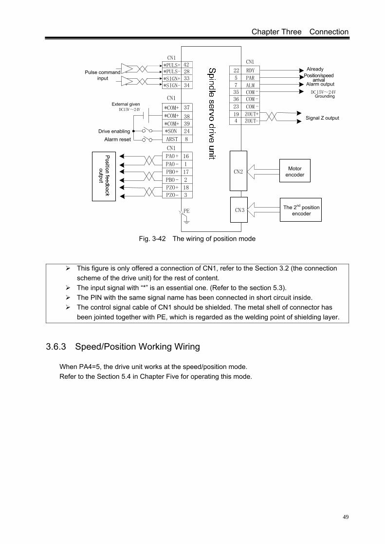
3.6.2 Wiring in Position Working
When PA4=0, the drive unit works in the position mode. Refer to the section 5.3 in Chapter Five for operating in the position mode.
Chapter Three Connection
49
Pulse command input 33
34
4228
*PULS+*PULS-
*SIGN-*SIGN+
RDY22 AlreadyPosition/speed
arrivalPAR5
7 ALM Alarm output
CN1
194
ZOUT+
35 COM -
COM -
COM -
36
23
DC15V~24VGrounding
Signal Z outputZOUT-
CN1
3839
*SON 24
External givenDC15V~24V
Drive enablingAlarm reset
16
1
2
18
3
8ARST
*COM+ 37
17
PE
CN1
CN2
CN3
Motor encoder
*COM+
*COM+
CN1
PAO +
PAO -
PBO -
PZO+
PZO-
PBO+
The 2nd position encoder
Fig. 3-42 The wiring of position mode
This figure is only offered a connection of CN1, refer to the Section 3.2 (the connection scheme of the drive unit) for the rest of content.
The input signal with “*” is an essential one. (Refer to the section 5.3). The PIN with the same signal name has been connected in short circuit inside. The control signal cable of CN1 should be shielded. The metal shell of connector has
been jointed together with PE, which is regarded as the welding point of shielding layer.
3.6.3 Speed/Position Working Wiring
When PA4=5, the drive unit works at the speed/position mode. Refer to the Section 5.4 in Chapter Five for operating this mode.

DAP、DAY Series Spindle Servo Drive Unit User Manual
50
Spindle servo drive unit
Position feedback output
Fig. 3-43 Wiring in speed/position mode
This figure is only offered a connection of CN1, refer to the section 3.2 for the rest of
content <The connection scheme of the drive unit>. The input signal with “*” is an essential one. (Refer to the Section 5.4). The PIN with the same signal name has been connected in short circuit inside. It is very essential to treat the shield for the CN1 control signal cable. The metal shell of
connector has been connected with the PE which is regarded as a welding point of shielding layer.

Chapter Four Display and Operation
51
CHAPTER FOUR DISPLAY AND OPERATION
4.1 Operation Panel
Refer to the Section 1.2.2 of the Chapter One for the function of each component is described on the spindle servo drive unit panel.
The details of key-press functions are shown below:
Key-press Name Specification
The key of ‘Adding’
1. Add the parameter serial number, parameter value; 2. Upturning the 2nd level menu; 3. The motor operation is accelerated when the manual operation is performed 4. Motor rotates CCW when JOG is operated.
The key of ‘Reduction’ or
‘Decrease'
1. Reduce the parameter serial number, parameter value; 2. The 2nd level menu downturn; 3. Motor operation decelerated when the manual operation is performed; 4. Motor rotates CW when JOG is operated.
The key of
‘Return’ Return to the previous menu or cancel the operation
The key of ‘Enter’ Enter the next menu or confirm the data setting.
The key of ‘Shift’
1. The Modified Bit of parameter serial number is selected 2. The Modified Bit of parameter value is selected
The details of panel indicators are shown below:
Panel indicator Function Specification
RUN Run indication The indicator lights up when motor excites after the power is turned on.
POWER Power indication The indicator lights up when the drive unit power is normally performed.
CCW CCW indication The indicator lights up when the motor rotates in CCW.
CW CW indication The indicator lights up when the motor rotates CW.
OREND The indication of orientating completion
When the positioning function is performed, after the motor is exactly stopped at the orientation position, in this case, the indicator is ON while the COIN signal is output.
PAR/SAR
Position/speed arrival indication
In the mode of position, the indicator lights up when the position arrival signal PAR outputs. In the mode of speed, the indicator lights up when the speed arrival signal SAR outputs.

DAP、DAY Series Spindle Servo Drive Unit User Manual
52
4.2 Menu Display
Drive unit monitor window is 6-bit LED digital tube, and its display content is controlled in terms of the menu’s form.
Fig. 4-1
The 1st menu is consisted of the state monitoring, parameter set, parameter administration, manual and JOG operation. And the rest of bits are composed of the 2nd level menu and data. Selection and operation of the 1st level is shown below:
Fig. 4-2
4.3 State Monitoring
is a monitoring state, the user can select different monitoring state, and set the value of parameter PA03. User, too, can set and the monitoring state when the drive unit is powered on.
Parameter value
Initial monitor at power on
OperationMonitoring
example Description
PA3=0 Motor speed 1000r/min [1]
PA3=1
Current motor position is low for 5-bit (pulse) [2]

Chapter Four Display and Operation
53
PA3=2 Current motor position is high for 5-bit (×100000 pulse)
PA3=3
Position command is low for 5-bit (pulse) [2]
PA3=4 Position command is high for 5-bit (×100000 pulse)
PA3=5 Position error is low for 5-bit (pulse) [2]
PA3=6 Position error is high for 5-bit (×100000 pulse)
PA3=7 To be developed
Parameter value
Initial monitor at power on
OperationMonitoring
example Specification
PA3=8 The motor current is 2.3A.
PA3=9 The speed corresponding to the analog command is 1000r/min.
PA3=10 The current control mode is position one
PA3=11 Position command pulse frequency is 124kHZ
PA3=12 The speed command is 210r/min
PA3=13 To be
developed
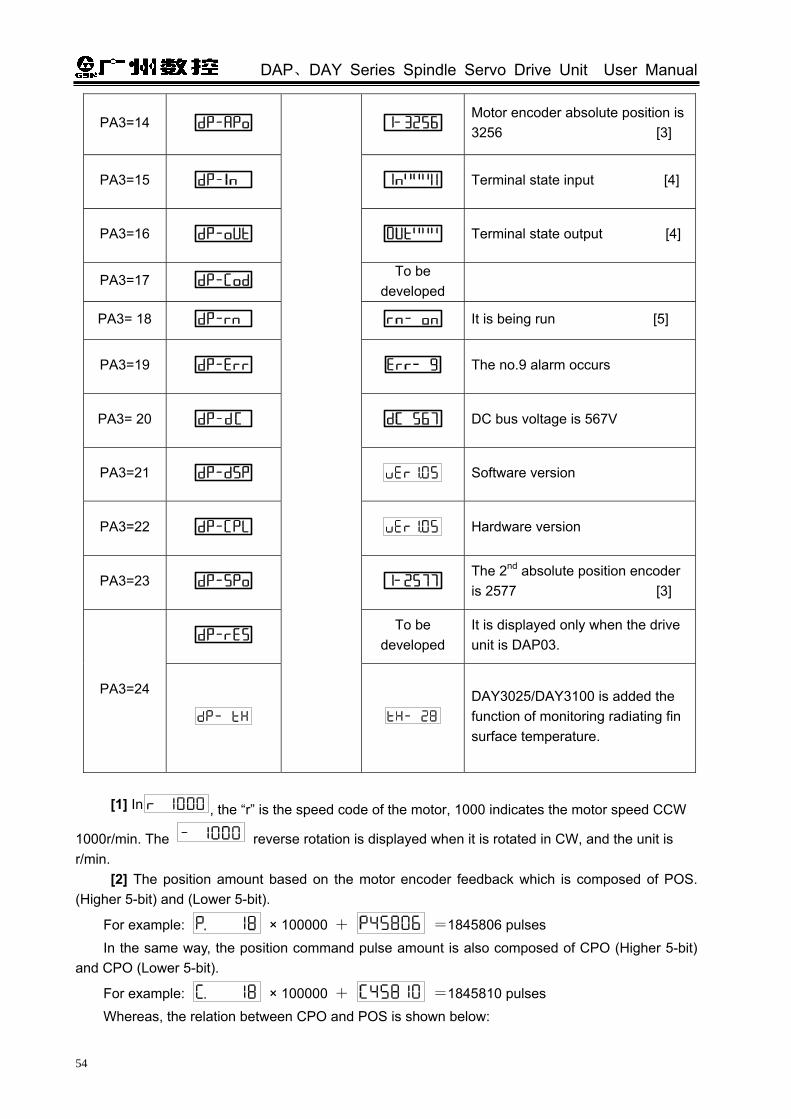
DAP、DAY Series Spindle Servo Drive Unit User Manual
54
PA3=14 Motor encoder absolute position is 3256 [3]
PA3=15 Terminal state input [4]
PA3=16 Terminal state output [4]
PA3=17 To be
developed
PA3= 18 It is being run [5]
PA3=19 The no.9 alarm occurs
PA3= 20 DC bus voltage is 567V
PA3=21 Software version
PA3=22 Hardware version
PA3=23 The 2nd absolute position encoder is 2577 [3]
To be
developed It is displayed only when the drive unit is DAP03.
PA3=24
DAY3025/DAY3100 is added the function of monitoring radiating fin surface temperature.
[1] In , the “r” is the speed code of the motor, 1000 indicates the motor speed CCW
1000r/min. The reverse rotation is displayed when it is rotated in CW, and the unit is r/min.
[2] The position amount based on the motor encoder feedback which is composed of POS. (Higher 5-bit) and (Lower 5-bit).
For example: × 100000 + =1845806 pulses In the same way, the position command pulse amount is also composed of CPO (Higher 5-bit)
and CPO (Lower 5-bit).
For example: × 100000 + =1845810 pulses Whereas, the relation between CPO and POS is shown below:

Chapter Four Display and Operation
55
In a similar way, the position error is consisted of EPO (Higher 5-bit) and EPO (Lower 5-bit).
For example: × 100000 + =4 pulses
When the motor is rotated for one circle, the displayed value of POS is changed with “encoder resolution ×4” pulse, one pulse corresponds the least angle displacement of the servo motor (360°/‘ encoder resolution ×4’)
[3] When the encoder is fixed, the Z pulse is fixed as zero position. The and
are separately displayed the pulse value of the zero point pulse which is offset by the position signal output by the motor encoder and the 2nd position encoder. If the number of encoder
linear is 1024, then the solution range between and is 0~4095, the position corresponding with the display value is absolute position.
The orientation position should be set in terms of the display value of or
when the orientation function is performed. (Refer to the section 6.6.1 for details)
[4] Refer to the Section 3.4.2 for terminal state input and the Section 3.4.3 for output terminal
state output [5] The display of operation state
Fig. 4-3
The operation method of calling out the state monitoring is as follows:
For example: There are two methods to call out the current state, which is shown below:
Method one: selecting the state monitoring directly.
Press for 14 times
Fig. 4-4
Method two: The state monitoring selection is performed based on parameters.

DAP、DAY Series Spindle Servo Drive Unit User Manual
56
Fig. 4-5
1. In method one, indicates that the drive unit has been detected the pulse Z, it is displayed as accurate value.
2. In method two, indicates that the drive unit has not been checked the pulse Z, the displayed value is stochastic and can not regard as reference value. The can be displayed when the motor is rotated for one circle.
4.4 Parameter Setting
When the parameter is set, the current value is Default Value one after the parameter has been initialized; in this case, the current value is Default Value after the motor default parameters are restored.
The operation for restoring the motor default parameter:
Relative parameters
Description Unit Parameter
range Default value
Applicable
Parameter password modification
0~9999 315 P,S PA0=315
The parameter other than PA1 and PA2 can be modified when PA0=315;
PA1 Motor type code 0~30 0 P,S
The motor (ZJY208—7.5—B5) default parameter setting shows an example, the type code of this motor is 24 checking from the Appendix A, namely, PA1=24.

Chapter Four Display and Operation
57
Fig. 4-6
1. 385 is a special password for setting the motor default parameter. The PA1 can be modified only when PA0=385.
2. The parameter related with the motor is written by default in terms of the operation of the motor default parameter, the user can also judge whether the default parameter of the drive unit is suitable for the motor of the drive based upon the value (Refer to the Appendix A) of PA1 parameter. The motor operation may irregular if the PA parameter value does not correspond with the motor’s type code.
3. The parameter can be affected after entering the , in this case, the modified
parameter value are responded to the control immediately. If you are not satisfied
with the modified parameter value, press the instead of the , the
parameter value is changed into the previous one.
The operation of initial parameter:
1. The ‘ ’ is controlled while the drive unit is ON, the current value of the drive unit is regarded as the default value;
2. If the 2nd position encoder is not connected with CN3, the Err-24 alarm may occur, and it is necessary to set the PA66=1; If the temperature sensor of motor is not connected the CN2 OH1 (CN2-13) signal, and the Err-5 alarm may occur, it is necessary to set PA73=1;
3. The initial operation has been executed after the parameter write-in is performed. Steps for modifying the PA24 value -2045 into 2045:
The ‘ ’ key shift function is introduced in parameter set.

DAP、DAY Series Spindle Servo Drive Unit User Manual
58
Fig. 4-7
In the above example, directly add by degree at the LED2-bit by employing the shift key, -45 is not changed into 1045, but -45+1000=955, and this result is drive unit calculation.
4.5 Parameter Administration
In parameter administration, the parameter write-in, read-in, backup and recovery backup, as well as the operation of calling the parameter default, which are described in the drive unit. The data memory relation of parameter administration is shown below:
System power on: Memory
Parameter write-in
: EEPROM parameter area
Parameter read : Memory
Parameter backup : EEPROM backup area
Backup recovery : Memory
Call out the default :the default parameters
Memory,EEPROM parameter area
EEPROM parameter area
EEPROM parameter area
Memory
Memory
EEPROM backup area
Fig. 4-8
EE-Set Parameter write-in, it means that the parameter in the memory is written into the EEPROM parameter area. Only the parameter value in the memory is changed after the user has modified the parameter, and the original value may restore when the power is turned on next time. If you want to change the parameter value perpetually, write the parameter value into the EEPROM parameter area, the modified value may be used after the power is turned on later.
EE-rd Parameter read-in, it means that the data in EEPROM parameter area are read into
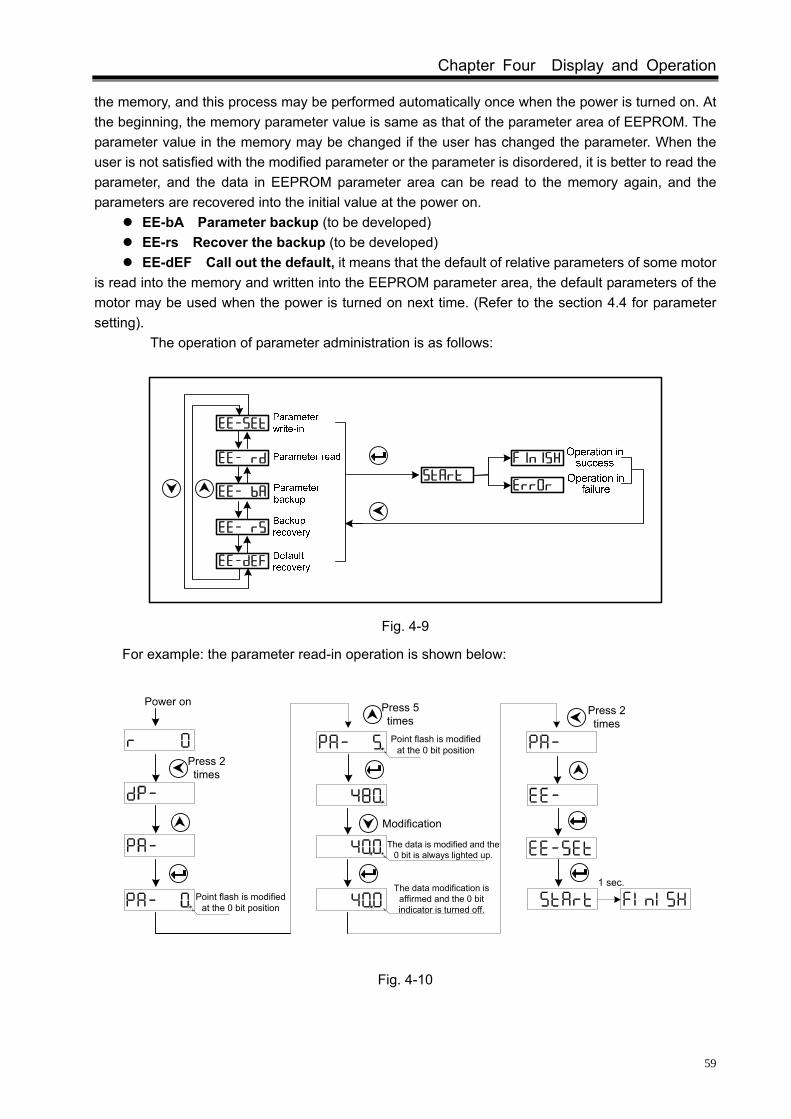
Chapter Four Display and Operation
59
the memory, and this process may be performed automatically once when the power is turned on. At the beginning, the memory parameter value is same as that of the parameter area of EEPROM. The parameter value in the memory may be changed if the user has changed the parameter. When the user is not satisfied with the modified parameter or the parameter is disordered, it is better to read the parameter, and the data in EEPROM parameter area can be read to the memory again, and the parameters are recovered into the initial value at the power on.
EE-bA Parameter backup (to be developed) EE-rs Recover the backup (to be developed) EE-dEF Call out the default, it means that the default of relative parameters of some motor
is read into the memory and written into the EEPROM parameter area, the default parameters of the motor may be used when the power is turned on next time. (Refer to the section 4.4 for parameter setting).
The operation of parameter administration is as follows:
Fig. 4-9
For example: the parameter read-in operation is shown below:
Press 2 times
Modification
Point flash is modified at the 0 bit position
The data is modified and the 0 bit is always lighted up.
Point flash is modified at the 0 bit position
The data modification is affirmed and the 0 bit indicator is turned off.
1 sec.
Power on Press 5 times
Press 2 times
Fig. 4-10

DAP、DAY Series Spindle Servo Drive Unit User Manual
60
CHAPTER FIVE DEBUGGING
The debugging method is introduced based upon the evaluation of PA4 parameter in this chapter.
Relative parameter
Significance Unit Parameter
range Default value
Applicable
Working selection 0~5 1 P,S PA4
PA4=0: Position mode; The rotation direction and angle of the motor are assigned by the digital pulse
or data communication, the drive unit rotates the motor’s rotor which is performed in terms of the specified direction and speed. Its angle (position) and speed can be controlled. PA4=1: Speed mode;
The rotation direction and speed of the motor are assigned by the analog voltage or data communication, the drive unit rotates the motor’s rotor which is performed in terms of the specified direction and speed. PA4=2: Manual operation;
In the Sr- menu, the acceleration or deceleration can be performed by pressing ‘ and ’. PA4=3: JOG operation;
In the Jr- menu, the CCW or CW operation can be performed by pressing ‘ and ’ at the set JOG speed by parameter. PA4=4: To be developed; PA4=5: Speed/position mode.
In this mode, the input point VP (speed/position shift) is OFF, after enabling, the drive unit will be worked at a speed mode; when the input point VP is ON, the drive unit is firstly performed the orientation function, then shift to the position mode till the VPO (speed/position state) signal is output.
Generally, a new drive unit should be performed 4 steps, which are shown below:
This chapter is mainly described the previous three steps, so that the user can use the servo drive device easily. Refer to the Chapter Six <Function Debugging> for function debugging which can be performed depended on the different requirements of users.
It is recommended that the manual or JOG operation can be performed without connecting the loading when the user uses the drive unit at the first time. Ensure that the drive unit and motor can be worked normally after transiting or installing, and the default parameters of the adapted motor should be affected.
After the drive unit and motor work normally, the CN1 control signal can be connected while the loading is not connected, the debugging and operating can be performed in the mode of speed, position or the others
The loading can be connected after the signal connection, parameter setting and motor running are debugged normally, the operation can be performed with loading.

Chapter Five Debugging
61
5.1 Manual, JOG Operation
Firstly, the wiring is performed correctly in terms of the following figure. It is recommended that the motor load does not connect firstly.
Spindle drive unit
Encoder feedback
Fig. 5-1
Note: Refer to the section 3.2 of the drive unit connection scheme #2 for KM1 control. The check is performed before the power is turned on till the wiring is correct, the description is
shown below:
Checked items Checked method
Whether the specification of the drive unit, motor and brake resistance are matched.
Check this manual for the drive unit, motor and the nameplate of the brake resistance
Whether connect the correct breaker or contactor;
Refer to the appendix B for the selection of peripheral equipment
Whether the wiring R, S, T, PE, P, B and U, V, W, PE are connected correctly.
Confirm the on-site power supply; use a multimeter to measure if it is necessary.
Whether the motor encoder feedback signal is connected appropriately.
Refer to the Section 3.5 of this User Manual
Whether the main circuit terminal screw is fixed;
Check whether the parts are loosened using the screw driver.
Firstly, the cooling fan of the motor is ON to check whether the rotation direction is correct.
The cooling fan is blown from the axis extension terminal to the end of the motor, if its direction is incorrect, any two phases of the power cable U, V and W of the fan can be exchanged.
The power can be turned on after the connection is confirmed. The time sequence is shown
below:
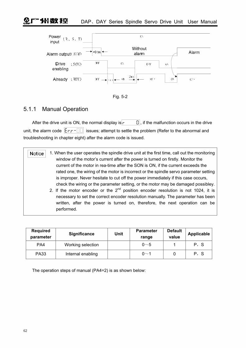
DAP、DAY Series Spindle Servo Drive Unit User Manual
62
Fig. 5-2
5.1.1 Manual Operation
After the drive unit is ON, the normal display is , if the malfunction occurs in the drive
unit, the alarm code issues; attempt to settle the problem (Refer to the abnormal and troubleshooting in chapter eight) after the alarm code is issued.
1. When the user operates the spindle drive unit at the first time, call out the monitoring window of the motor’s current after the power is turned on firstly. Monitor the current of the motor in rea-time after the SON is ON, if the current exceeds the rated one, the wiring of the motor is incorrect or the spindle servo parameter setting is improper. Never hesitate to cut off the power immediately if this case occurs, check the wiring or the parameter setting, or the motor may be damaged possibley.
2. If the motor encoder or the 2nd position encoder resolution is not 1024, it is necessary to set the correct encoder resolution manually. The parameter has been written, after the power is turned on, therefore, the next operation can be performed.
Required parameter
Significance Unit Parameter
range Default value
Applicable
PA4 Working selection 0~5 1 P,S
PA33 Internal enabling 0~1 0 P,S
The operation steps of manual (PA4=2) is as shown below:
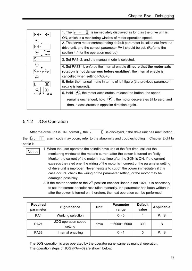
Chapter Five Debugging
63
1. The is immediately displayed as long as the drive unit is ON, which is a monitoring window of motor operation speed. 2. The servo motor corresponding default parameter is called out from the drive unit, and the correct parameter PA1 should be set. (Refer to the section 4.4 for the operation method)
3. Set PA4=2, and the manual mode is selected.
4. Set PA33=1, enforce the internal enable (Ensure that the motor axis rotation is not dangerous before enabling); the internal enable is cancelled when setting PA33=0. 5. Enter the manual menu in terms of left figure (the previous parameter setting is ignored).
6. Hold , the motor accelerates, release the button, the speed
remains unchanged; hold , the motor decelerates till to zero, and then, it accelerates in opposite direction again.
5.1.2 JOG Operation
After the drive unit is ON, normally, the is displayed, if the drive unit has malfunction,
the alarm code may occur, refer to the abnormity and troubleshooting in Chapter Eight to settle it.
1. When the user operates the spindle drive unit at the first time, call out the monitoring window of the motor’s current after the power is turned on firstly. Monitor the current of the motor in rea-time after the SON is ON. If the current exceeds the rated one, the wiring of the motor is incorrect or the parameter setting of drive unit is improper. Never hesitate to cut off the power immediately if this case occurs, check the wiring or the parameter setting, or the motor may be damaged possibley.
2. If the motor encoder or the 2nd position encoder linear is not 1024, it is necessary to set the correct encoder resolution manually, the parameter has been written in, after the power is turned on, therefore, the next operation can be performed.
Required parameter
Significance Unit Parameter
range Default value
Applicable
PA4 Working selection 0~5 1 P,S
PA21 JOG operation speed
setting r/min -6000~6000 300 S
PA33 Internal enabling 0~1 0 P,S
The JOG operation is also operated by the operator panel same as manual operation. The operation steps of JOG (PA4=3) are shown below:

DAP、DAY Series Spindle Servo Drive Unit User Manual
64
1. The is immediately displayed as long as the drive unit is ON, which is a monitoring window of motor operation speed. 2. Call out the corresponding default parameter of the servo motor in
the drive unit, the correct parameter PA1 should be set. (Refer to the section 4.4 for operating) 3. Set PA4=3 to select the JOG operation; Set PA21=500, the JOG speed is set to 500 r/min.
4. Set PA33=1, enforce the internal enabling. (Ensure that the motor axis rotates may not hazard before enabling) (Set PA33=0, the internal enabling is cancelled.) 5. Enter the JOG menu based on the left figure (The previous parameter setting is omitted)
6. Hold , the motor runs based upon the speed of 500 r/min set by
PA21; hold , the motor runs oppositely set by PA21; release the button, the motor stops at zero speed.
When the manual or JOG operation is performed, if the abnormity, such as vibration and noise, of the motor are generated, the speed loop parameter of PA5, PA6 and PA8 should be debugged. Refer to the section 6.1 for details (The explanation of the basic capability parameter debugging)
5.2 Running in Speed Mode
5.2.1 Analog Voltage Commands
① Wiring should be connected correctly in terms of the section 3.6.1 (A), note that the required input signals should be connected in the following table.
Required input signal
Terminal number
Function
*COM+ CN1-37、38、39The common terminal of the input point is the controllable power input terminal.
*VCMD+ *VCMD-
CN1-14 CN1-15
Analog voltage command input
*SON CN1-24 Servo enabling signal.
*SFR CN1-9 PA46=1, CCW starts to input; PA46=0, it is drive enabling allowable signal.
*SRV CN1-25 PA46=1, CW starts to input; PA46=0, it is disabled.
② After the correct connection is confirmed, all input signals are OFF, the required parameters are set after the power is turned on.

Chapter Five Debugging
65
Required parameter
Parameter description
PA4=1 Speed mode selection
PA22=1 The speed command selects the external analog voltage command.
The motor speed corresponding to the default analog 10V is 6000r/min.
PA42=6000
The speed range corresponding to 10V is set, the factory value is 10V corresponding 6000r/min. For example: if PA42=5000, 10V command corresponding to the motor speed 5000r/min, 5V command corresponding to the motor speed 2500r/min, 1V command corresponding to the motor speed 500r/min.
PA45
PA46
The external analog voltage command range is indicated as -10V~+10V;
PA45=0
The voltage command is positive, and the motor starts and rotates CCW; The voltage command is negative, and the motor starts CW.
PA46=0
PA45=1
The voltage command is positive, and the motor starts CW; The voltage command is negative, and the motor starts CCW.
The external analog voltage command range is indicated as 0~+10V.
PA45=0 SFR is ON, and the motor starts CCW; SRV is ON, and the motor starts CW.
PA46=1
PA45=1 SFR is ON, and the motor starts CW;
③ Basic debugging operation 1. The required parameter set is completed, the parameter write-in operation is performed (Refer
to the operation in parameter administration in section 4.5). 2. The least analog command is offered and the SON is ON, SFR (or SRV) is ON, and then the
motor should be operated with the command. In this case, the indicators, such as ‘RUN’, ‘CCW’ or ‘CW’, are lighted up on this panel.
When PA46=0, the SON and SFR signals should be set to ON, the motor can be turned on and excited, and then the SFR is an enabling allowance signal;
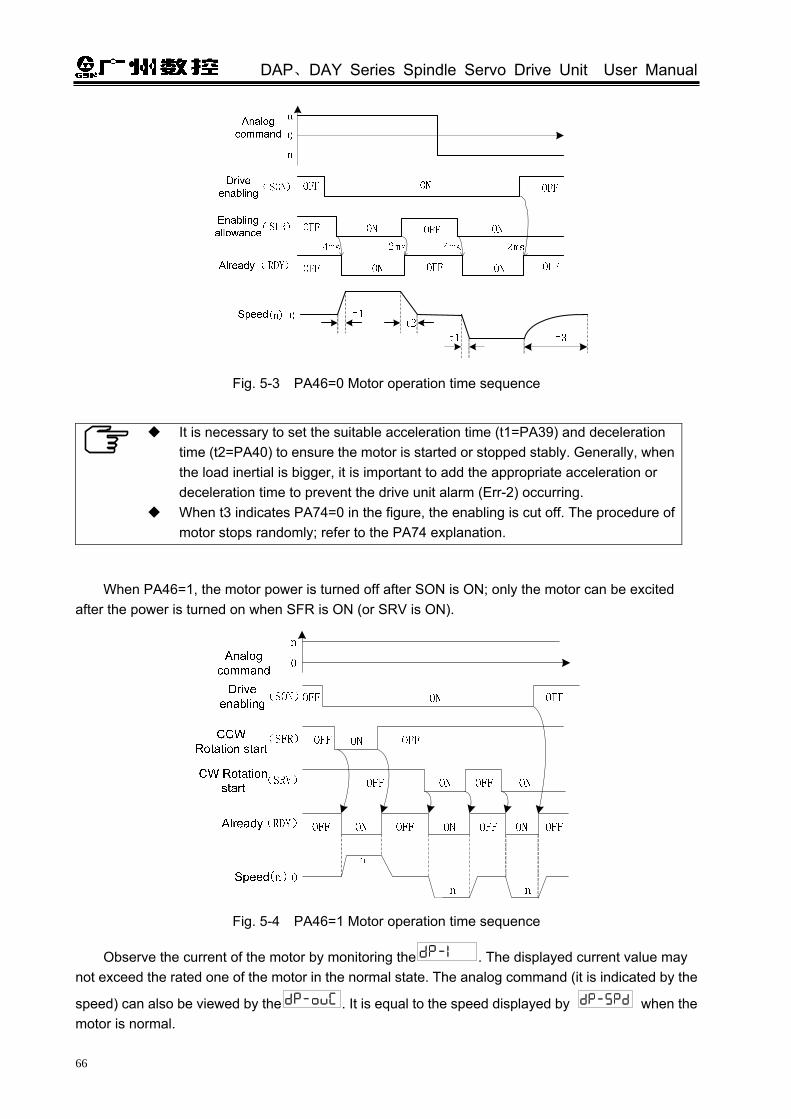
DAP、DAY Series Spindle Servo Drive Unit User Manual
66
Fig. 5-3 PA46=0 Motor operation time sequence
It is necessary to set the suitable acceleration time (t1=PA39) and deceleration
time (t2=PA40) to ensure the motor is started or stopped stably. Generally, when the load inertial is bigger, it is important to add the appropriate acceleration or deceleration time to prevent the drive unit alarm (Err-2) occurring.
When t3 indicates PA74=0 in the figure, the enabling is cut off. The procedure of motor stops randomly; refer to the PA74 explanation.
When PA46=1, the motor power is turned off after SON is ON; only the motor can be excited after the power is turned on when SFR is ON (or SRV is ON).
Fig. 5-4 PA46=1 Motor operation time sequence
Observe the current of the motor by monitoring the . The displayed current value may not exceed the rated one of the motor in the normal state. The analog command (it is indicated by the
speed) can also be viewed by the . It is equal to the speed displayed by when the motor is normal.

Chapter Five Debugging
67
3. Enlarge the analog command gradually, and improve the operation speed of the motor step by step, at this time, monitor whether the vibration and noise are generated, the speed is stable, and whether the motor current exceeds the rated value when the motor is operated.
4. When the motor runs from zero speed to the positive top speed or from the zero speed to the negative maximum speed normally, the user can debug other functions
The abnormities and troubleshootings are shown below during in the mode of analog command speed:
Serial number
Abnormity during debugging Troubleshooting
1
No data in the monitoring window
after the analog command is offered;
Check the command system and controllable cable
2
The data occurs in the monitoring window after enabling, but not data in , namely, the speed command issues but the motor does not run;
Check the setting of “required parameters” or check the enabling signal cable. It is very convenient to check I/O by the display content of . (Refer to the Section 3.4.2 for switch input point)
3 The motor rotation directions are different;
Refer to the Section 6.2 of Chapter Six for the shifting of motor rotation direction.
4
The abnormal may occur such as the vibration or noise; the motor axis vibrates when the orientation is performed;
1. Check whether the shielded cable is correct 2. Refer to the section 6.1 of Chapter Six for details (Basic capability parameter debugging explanation)
5 The motor can only be operated in single direction;
1. Detect the command resource mode, and check the setting of PA46; 2. Check whether the analog command input cable is connected inversely.
6 0V command is offered, the motor may move slightly;
Refer to the adjustment offset in Section 6.6.2 in Chapter Six.
5.2.2 Internal Digital Command
① Firstly, refer to the wiring diagram in the Fig. (B) of Section 3.6.1 to connect, note that the required input signals should be connected as follows:
Required input signal Terminal number Function
*COM+ CN1-37、38、39The common terminal of input point is controllable power input terminal.
*SON CN1-24 The motor enabling can be controlled separately in servo enabling signal mode.
*SP0 CN1-10 Speed selection 0.
*SP1 CN1-40 Speed selection 1
*SP2 CN1-26 Speed selection 2

DAP、DAY Series Spindle Servo Drive Unit User Manual
68
② Confirm the correct connect, keep all input signals are OFF, the required parameter is set after the power is turned on.
Required parameter
Parameter description
PA4=1 Speed mode selection.
PA22=0 Speed command selects the internal one.
PA24 ~
PA30
I/O state of speed selection Internal
command default
Operation speed SP0
(CN1-10)SP1
(CN1-40) SP2
(CN1-26) 0 r/min OFF OFF OFF
PA24=1000 Internal speed 1
ON OFF OFF
PA25=-500 Internal speed 2
OFF ON OFF
PA26=2000 Internal speed 3
ON ON OFF
PA27=-3000 Internal speed 4
OFF OFF ON
PA28=5000 Internal speed 5
ON OFF ON
PA29=3000 Internal speed 6
OFF ON ON
PA30=10 Internal speed 7
ON ON ON
③ Basic debugging operation 1. After the required parameter setting is completed, and the parameter writing is performed
(Refer to the operation explanation of parameter management in the section 4.5) 2. Firstly, the SON is set to ON, the motor is excited after the power is turned on and kept on the
zero speed, in this case, the light of ‘RUN’ is lighted up on this panel. Then, the SP0 is set to ON, the motor should be operated based on the ‘internal speed 1’, the speed is 1000 r/min by default. View the current’s flow by .
Observe the current of the motor by monitoring the . The displayed current value may not exceed the rated one of the motor in the normal state.
3. The SP1 and SP2 are set to ON gradually, (Refer to the following figure); the motor separately
runs at the internal speed in seven different steps. Monitor whether the vibration or noise of the motor’s operation is generated, the speed is stable, and the motor’s current exceeds the rated value.
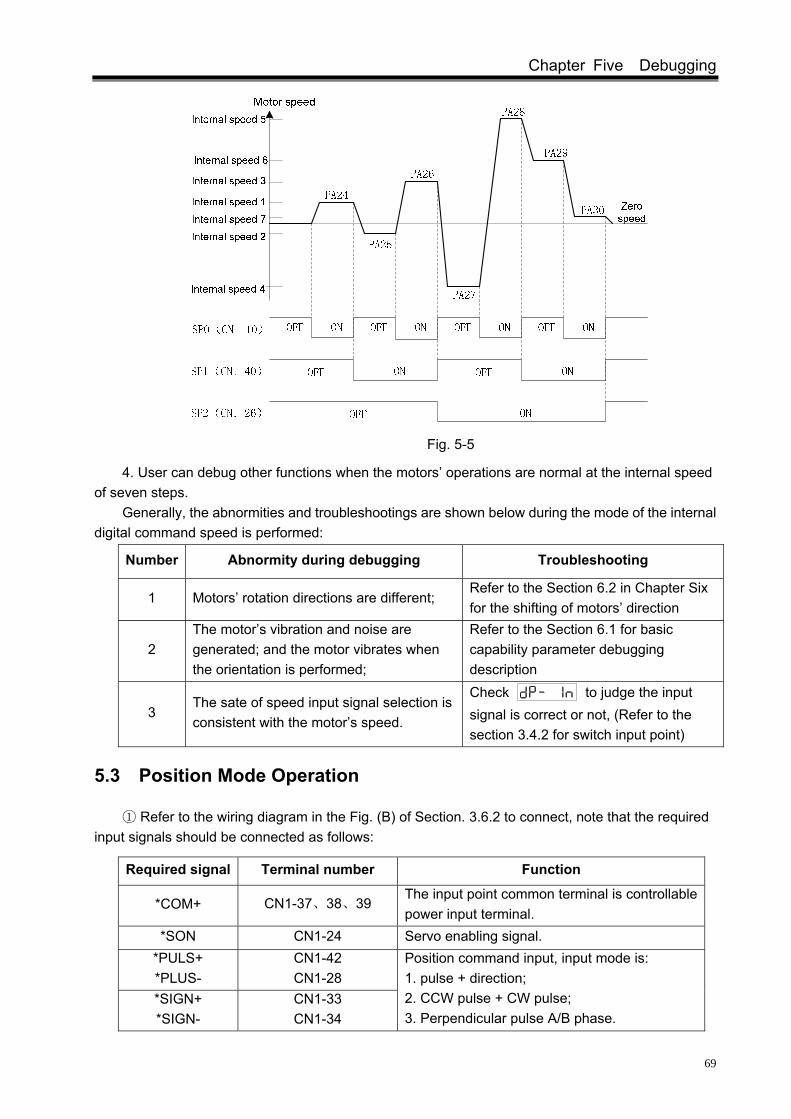
Chapter Five Debugging
69
Fig. 5-5
4. User can debug other functions when the motors’ operations are normal at the internal speed of seven steps.
Generally, the abnormities and troubleshootings are shown below during the mode of the internal digital command speed is performed:
Number Abnormity during debugging Troubleshooting
1 Motors’ rotation directions are different; Refer to the Section 6.2 in Chapter Six for the shifting of motors’ direction
2 The motor’s vibration and noise are generated; and the motor vibrates when the orientation is performed;
Refer to the Section 6.1 for basic capability parameter debugging description
3 The sate of speed input signal selection is consistent with the motor’s speed.
Check to judge the input signal is correct or not, (Refer to the section 3.4.2 for switch input point)
5.3 Position Mode Operation
① Refer to the wiring diagram in the Fig. (B) of Section. 3.6.2 to connect, note that the required input signals should be connected as follows:
Required signal Terminal number Function
*COM+ CN1-37、38、39 The input point common terminal is controllable power input terminal.
*SON CN1-24 Servo enabling signal. *PULS+ *PLUS-
CN1-42 CN1-28
*SIGN+ *SIGN-
CN1-33 CN1-34
Position command input, input mode is: 1. pulse + direction; 2. CCW pulse + CW pulse; 3. Perpendicular pulse A/B phase.

DAP、DAY Series Spindle Servo Drive Unit User Manual
70
② Confirm the correct connection; keep all input signals OFF, the required parameters are set after the power is turned on.
Required parameter
Parameter specification
PA4=0 Position mode selection. Position command electronic gear function:
PA12 is pulse command multiple coefficient; PA13 is pulse command frequency-division coefficient.
PA12=1 PA13=1
Set the electronic gear ratio of position command to match with the various pulse commands. The formula of electronic gear ratio is:
,
(Refer to the Section 6.5.1 of Chapter Six for details)
The selection of the position command pulse: pulse + direction.
PA14=0 PA14=0: pulse + direction; PA14=1: CCW pulse + CW pulse; PA14=2: two-phase perpendicular pulse input; (Refer to the Section 3.4.2 in Chapter Three for position command input)
Position command direction is reverse.
PA15 PA15=0: position command “standard mode”; PA15=1: position command “CW rotation start mode”. (Refer to the Section 6.2 in Chapter Six)
③ Basic debugging operation 1. The required parameter setting is finished, and the parameter reading operation is performed
(Refer to the operation explanation of on Section 4.5 for the parameter management). 2. Firstly, the SON is set to ON, the motor is excited after the power is turned on and kept on the
zero speed, in this case, the light of ‘RUN’ is lighted up on this panel. The motor of position pulse command offered a less frequency that should operate.
View the motor’s current by monitoring . Normally, the displayed current value does not
exceed the rated current of the motor. When PA12 and PA13 are all set to 1, the drive unit can read
the pulse number of position command after it is performed a command by , which is equal
to the pulse number displayed with . When the electron gear ratio is not 1:1, the pulse
number of should multiply the electron gear ratio. The motor can be driven with the mode of the pulse + direction as follows:
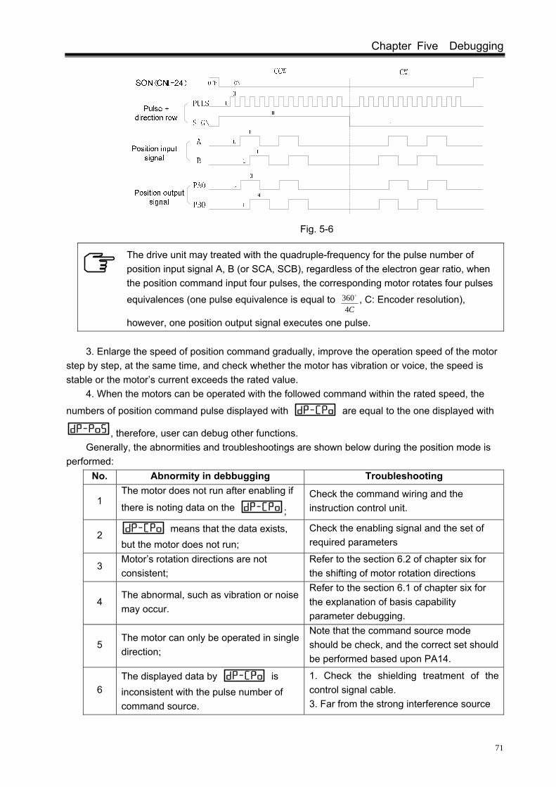
Chapter Five Debugging
71
Fig. 5-6
The drive unit may treated with the quadruple-frequency for the pulse number of position input signal A, B (or SCA, SCB), regardless of the electron gear ratio, when the position command input four pulses, the corresponding motor rotates four pulses
equivalences (one pulse equivalence is equal to C4
360o , C: Encoder resolution),
however, one position output signal executes one pulse. 3. Enlarge the speed of position command gradually, improve the operation speed of the motor
step by step, at the same time, and check whether the motor has vibration or voice, the speed is stable or the motor’s current exceeds the rated value.
4. When the motors can be operated with the followed command within the rated speed, the
numbers of position command pulse displayed with are equal to the one displayed with
, therefore, user can debug other functions.
Generally, the abnormities and troubleshootings are shown below during the position mode is performed:
No. Abnormity in debbugging Troubleshooting
1 The motor does not run after enabling if
there is noting data on the ; Check the command wiring and the instruction control unit.
2 means that the data exists, but the motor does not run;
Check the enabling signal and the set of required parameters
3 Motor’s rotation directions are not consistent;
Refer to the section 6.2 of chapter six for the shifting of motor rotation directions
4 The abnormal, such as vibration or noise may occur.
Refer to the section 6.1 of chapter six for the explanation of basis capability parameter debugging.
5 The motor can only be operated in single direction;
Note that the command source mode should be check, and the correct set should be performed based upon PA14.
6 The displayed data by is inconsistent with the pulse number of command source.
1. Check the shielding treatment of the control signal cable. 3. Far from the strong interference source

DAP、DAY Series Spindle Servo Drive Unit User Manual
72
5.4 Speed/Position Mode Operation
① Refer to the wiring diagram in the Section (B) of Fig. 3.6.3 to connect, note that the required input signals should be connected as follows:
Required input signal
Terminal number
Function
*COM+ CN1-37、38、39The input common terminal is the one of power control input.
*VCMD+ *VCMD-
CN1-14 CN1-15
Analog voltage command input point.
*SON CN1-24 Servo enabling signal
*SFR CN1-9 PA46=1, CCW rotation start input; PA46=0, drive enabling allowance signal.
*SRV CN1-25 PA46=1, CW rotation start input; PA46=0, disabled.
*VP CN1-12 Speed/position shifting: (The function is enabled when PA4 is equal to 5)
*VPO CN1-44 Speed/position state output. (It is enabled when PA4 is equal to 5)
*PULS+ *PLUS-
CN1-42 CN1-28
*SIGN+ *SIGN-
CN1-33 CN1-34
Position command input mode: 1. Pulse + direction; 2. CCW pulse + CW pulse; 3. Perpendicular pulse A/B phase.
② Confirm the connection, keep all input signals OFF, the required parameters are set after the power is turned on.
Required parameter
Parameter description
PA4=5 The selection of peed /position mode.
PA22 Speed command selection: PA22=0, internal speed command; PA22=1, external analog voltage speed command.
The external analog voltage command is indicated as -10V~+10V; PA45=0 Voltage command is positive, the motor starts
CCW; Voltage command is negative, the motor starts CW;
PA46=0
PA45=1 Voltage command is positive, the motor starts CW;Voltage command is negative, the motor starts CCW;
The external analog voltage command is indicated as 0~+
10V PA46=1
PA45=0 SFR is ON, the motor starts CCW;

Chapter Five Debugging
73
SRV is ON, the motor starts CW; PA45=1 SFR is ON, motor starts CW;
SRV is ON, motor starts CCW; Mode shifts from position mode to speed motor.
PA76
In the mode of speed/position, the transition mode is selected from the position control switching to the speed control. PA76=0: When VP skips to OFF, switch to the speed mode after the control operation position command is completed. PA76=1: When VP skips to OFF, shift to the speed control immediately regardless of the completion of position command.
Required parameter
Parameter description
Speed/position shifts the reference position.
PA77 When the drive unit is shifted from the speed control to the position control, it may be searched and stopped at the reference position set by PA77 in terms of the positioning speed set by PA55, and then waits for the position command. (Refer to the section 6.6.1 orientation function for the whole process) Position command electronic gear function:
PA12 is pulse command multiplication coefficient; PA13 is pulse command frequency-division coefficient.
PA12=1 PA13=1
The electronic gear ratio of position command is set to match the pulse commands. Its calculation formula is shown below:
,
(Refer to the Section 6.5.1 in Chapter Six for the detailed calculation method)
The position command pulse mode is: pulse + direction
PA14=0 PA14=0: Pulse + direction; PA14=1: CCW pulse + CW pulse; PA14=2: Two-phase orthogonal pulse input; (refer to the Section 3.4.2 in Chapter Three for position command input) Position command direction reverse
PA15 PA15=0: Position command “standard mode”; PA15=1: Position command “reverse mode”. (Refer to the Section 6.2 in Chapter Six)
③ Basic debugging operation 1. The parameter write-in operation is performed after the required parameter setting is created
(refer to the operation specification of parameter administration in Section 4.5). 2. Speed/position shifts in terms of the input state of VP (CN1-12): That is: VP (CN1-12) is ON, the drive unit is position mode, and the function is consistent with it
when PA4=0; VP (CN1-12) is OFF, the drive unit is speed mode, and the function is consistent with it when

DAP、DAY Series Spindle Servo Drive Unit User Manual
74
PA4=1. The shift processing is shown below:
a) The switch processing in PA76=0
b) The switch processing in PA76=1
Fig. 5-7
3. VP (CN1-12) signal is OFF state by default, which the drive is debugged in the speed mode firstly. Refer to the Section 5.2.1 for details.
4. After the speed mode operation is normal, the drive unit can be shifted to the position mode directly in the case of the motor enabling.
When VP (CN2-12) is ON, the drive unit is shifted to the position mode in terms of the time sequence of figure 5-4-1 or 5-4-2; in this case, VPO (CN1-44) signal is conducted with COM-. The debugging operation is performed based upon the Section 5.3.
The abnormal case can be separately referred to the speed mode and position mode troubleshooting during the speed/position mode is operated.
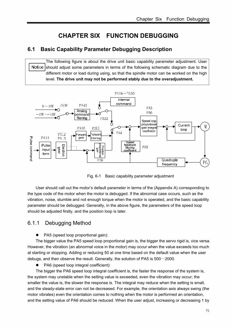
Chapter Six Function Debugging
75
CHAPTER SIX FUNCTION DEBUGGING
6.1 Basic Capability Parameter Debugging Description
The following figure is about the drive unit basic capability parameter adjustment. User should adjust some parameters in terms of the following schematic diagram due to the different motor or load during using, so that the spindle motor can be worked on the high level. The drive unit may not be performed stably due to the overadjustment.
Fig. 6-1 Basic capability parameter adjustment
User should call out the motor’s default parameter in terms of the (Appendix A) corresponding to
the type code of the motor when the motor is debugged. If the abnormal case occurs, such as the vibration, noise, stumble and not enough torque when the motor is operated, and the basic capability parameter should be debugged. Generally, in the above figure, the parameters of the speed loop should be adjusted firstly, and the position loop is later.
6.1.1 Debugging Method
PA5 (speed loop proportional gain): The bigger value the PA5 speed loop proportional gain is, the bigger the servo rigid is, vice versa.
However, the vibration (an abnormal voice in the motor) may occur when the value exceeds too much at starting or stopping. Adding or reducing 50 at one time based on the default value when the user debugs, and then observe the result. Generally, the solution of PA5 is 500~2000.
PA6 (speed loop integral coefficient): The bigger the PA6 speed loop integral coefficient is, the faster the response of the system is,
the system may unstable when the setting value is exceeded, even the vibration may occur; the smaller the value is, the slower the response is. The integral may reduce when the setting is small, and the steady-state error can not be decreased. For example, the orientation axis always swing (the motor vibrates) even the orientation comes to nothing when the motor is performed an orientation, and the setting value of PA6 should be reduced. When the user adjust, increasing or decreasing 1 by

DAP、DAY Series Spindle Servo Drive Unit User Manual
76
default, and then observe the effection. Note that the solution of PA6 is 1~20. The proportional gain of the speed loop and the integrate coefficient should be debugged
proportionally based upon the detailed servo motor’s type and loading. Generally, the bigger the load inertia is, the smaller the setting value is. In the case of the system vibration is not issued, two parameter values should be set bigger as far as possible.
The response curve is generated by the step command with one inertia load for driving one motor. Refer to the Fig. 6-2.
Curve 1 indicates that the speed step input curve is displayed when PA6=0, the motor characteristic is soft, the dynamic respondence is slower and the bigger steady state error occurs.
Curve 2 indicates that the speed step input curve is displayed when the evaluation both PA5 and PA6 are suitable, the motor’s rigidity is moderate and the dynamic response is fast;
Curve 3 indicates that speed step input curve is displayed when PA5 is less and PA6 is bigger, the instantaneous overshoot is the maximum and the motor vibration is easily caused.
Fig. 6-2 The response curve input by the step command
PA8 (speed feedback filtering coefficient):
The bigger the speed feedback filter coefficient value is, the faster the speed feedback responds. If the set value is excessive, the electromagnetic noise may occur in the motor; the less the set value is, the slower the speed feedback responds; if the set value is excessively small, the speed wave is increased, even the vibration may occur. User can increase or decrease 50 at the default value and then observe the result when the parameters are being adjusted. Note that the minimum value of PA8 should not be less than 50.
PA9 (position loop proportional gain): The drive unit position loop adopts the simple P adjustment. When the orientation function is
performed in the position and speed modes, the position closed-loop function is enabled.

Chapter Six Function Debugging
77
The bigger the value of the position loop proportional gain is, the faster the position command responds, the bigger the rigid is. If the value is excessively big, the vibration occurs in the motor caused by the position overrun when the motor starts or stops; the less the setting value is, the slower the response is, the bigger the followed error is. Add or reduce 5 once at the default value when the user adjusts, then view the result. Note that the solution range of PA9 is 25~60.
PA10 (position loop feedforward gain), PA11 (position loop feedforward filtering coefficient): PA10 adjusts the speed loop with the speed information of the position command, the setting
value is enlarged, while the followed error is reduced, the instantaneous overshoot and the vibration in the motor may easily occur.
Actually, the PA11 is smoothly treated the position command forward control, the bigger the setting value is, the faster the step speed command responds, the position overrun and vibration can be controlled while the command speed changes suddenly. When the speed is mutated, the less the setting value is, the less the result of feedforward control is, the less the vibration caused by the feedforward control is.
Generally, PA10 (position feedforward gain) and PA11 (position feedforward low-pass filter cut-off frequency) are not used possibly.
PA43 (analog command filtering coefficient): The less the analog command filtering cut-off frequency is, the stronger the interference signal
supression capability is, the less the value is, the slower the speed command responds, and vice versa. Increase or decrease 50 at every turn based upon the default value when the user adjusts, and then observe the result. Note that the least value of PA42 can not be less than 50.
6.1.2 The Application of Rigid Tapping
The rigid tapping belongs to the thread machining under the position closed-loop in the process of machining, so it is very necessary for the drive unit which owns the higher servo rigidity. The response to the command should be fast, and the position follow error should be reduced as much as possible. Therefore the higher speed loop gain of the drive unit should be set, in this case, the motor speed should be lower when the rigid tapping is performed, due to the motor may vibrate at high speed. As for the AC asynchronous spindle servo drive unit, two kinds of speed loop gain of should be required for general spindle machining and rigid tapping machining, so, the speed loop 2nd gain parameters PA78, PA79 and PA80 should be increased. The speed loop 2nd gain parameter input signal TAP is added in the CN1 interface; whereafter, the different machining application can be used different parameter configurations.
TAP(CN1-41) is OFF The PA5, PA6 and PA42 are enabled, and the time of acceleration or deceleration is determined by PA39 or PA40.
TAP(CN1-41)is ON The PA78, PA79 and PA80 are enabled, and the time parameter of acceleration or deceleration is disabled.

DAP、DAY Series Spindle Servo Drive Unit User Manual
78
Relative parameter
Name Unit Parameter
range Default Applicable
10V analog command corresponds to the top speed
when the 2nd speed loop gain is enabled.
r/min 0~15000 6000 S PA78
TAP (CN1-41) is valid when it is ON, and its function is same as that of PA42. (Refer to the analog voltage command on section 5.2.1 for details)
The 2nd proportional gain of the speed loop
Hz 10~3000 1000 S PA79
TAP (CN1-41) is valid when it is ON, and its function is same as PA5. (Refer to the debugging method in the Section 6.1.1) The 2nd integral coefficient of the
speed loop 1~3000 10 S
PA80 TAP (CN1-41) is valid when it is ON, and its function is same as PA6. (Refer to the debugging method on section 6.1.1)
The three parameters are also connected with the motor type code, and the default values are different depending on the different motors. Refer to the PA42, PA5 and PA6 for the debugging method. When the rigid tapping is actually performed, amplify the values of PA79 and PA80 as much as possible, enlarge the rigidity of the speed loop, the vibration should be avoided when the rigid tapping is performed therefore. Generally, it is recommended that the parameter range should be indicated as PA79(1000~2000), PA80(1~10).
6.2 Shifting Between the Motor Rotation Directions
Standard setting: 1. Only when all the parameters of the drive unit are set to default values; 2. The motor encoder signal (or the 2nd position feedback input signal) A/B phase pulse input is:
Fig. 6-3
And then, as for the speed or position mode, the relation between the command and the rotation direction are accorded with the ‘standard set’.
Reverse mode: In the case of the servo motor wiring does not change, the rotation direction of servo motor is
“Reverse mode” for the drive unit.
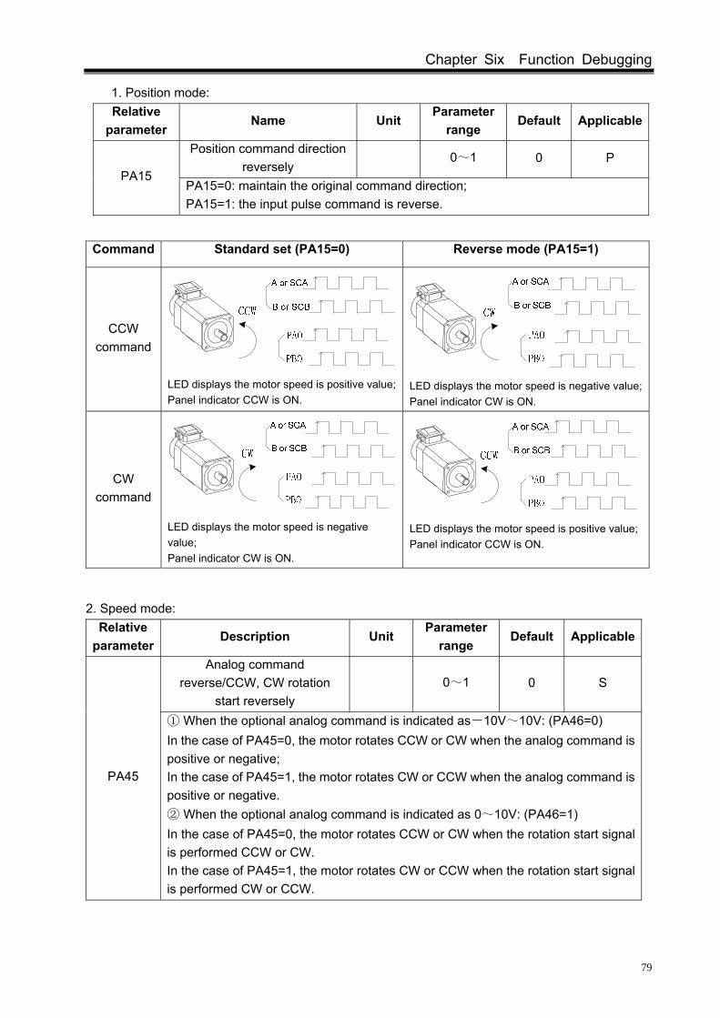
Chapter Six Function Debugging
79
1. Position mode: Relative
parameter Name Unit
Parameter range
Default Applicable
Position command direction reversely
0~1 0 P PA15
PA15=0: maintain the original command direction; PA15=1: the input pulse command is reverse.
Command Standard set (PA15=0) Reverse mode (PA15=1)
CCW command
LED displays the motor speed is positive value;Panel indicator CCW is ON.
LED displays the motor speed is negative value;Panel indicator CW is ON.
CW command
LED displays the motor speed is negative value; Panel indicator CW is ON.
LED displays the motor speed is positive value; Panel indicator CCW is ON.
2. Speed mode: Relative
parameter Description Unit
Parameter range
Default Applicable
Analog command reverse/CCW, CW rotation
start reversely 0~1 0 S
PA45
① When the optional analog command is indicated as-10V~10V: (PA46=0) In the case of PA45=0, the motor rotates CCW or CW when the analog command is positive or negative; In the case of PA45=1, the motor rotates CW or CCW when the analog command is positive or negative. ② When the optional analog command is indicated as 0~10V: (PA46=1) In the case of PA45=0, the motor rotates CCW or CW when the rotation start signal is performed CCW or CW. In the case of PA45=1, the motor rotates CW or CCW when the rotation start signal is performed CW or CCW.

DAP、DAY Series Spindle Servo Drive Unit User Manual
80
Standard set (PA45=0) Reverse mode (PA45=1)
SFR command (PA46=1)
LED displays the motor speed is positive value, and the panel indicator lights up CCW
CW
LED displays the motor speed is negative value, and the panel indicator lights up CW.
SRV command (PA46=1)
LED displays the motor speed is negative value, and the panel indicator lights up CW.
CCW
LED displays the motor speed is positive value, and the panel indicator lights up CCW.
Positive voltage
(PA46=0)
CCW
LED displays the motor speed is positive value, and the panel indicator lights up CCW.
CW
LED displays the motor speed is negative value, and the panel indicator lights up CW.
Negative voltage
(PA46=1)
CW
LED displays the motor speed is negative value, and the panel indicator lights up CW.
CCW
LED displays the motor speed is positive value, and the panel indicator lights up CCW.
6.3 Position Signal Output
The position feedback signal of the encoder can be output by CN1 interface of the drive unit.
Output form Output signal
name Terminal name Function
Difference output
PAO+ PAO-
CN1-16 CN1-1
Encoder position feedback signal phase A
Difference output
PBO+ PBO-
CN1-17 CN1-2
Encoder position feedback signal phase B
Difference output
PZO+ PZO-
CN1-18 CN1-3
Encoder position feedback signal phase Z

Chapter Six Function Debugging
81
PG
CN2
CN3
PG
Spindle servo motor
The 2nd position encoder
PA66=1
Position loop
PA66=0
PA69=0
PA69=1 Quadruple frequency
PA71=1
PA71=0 PAO,PBOreverse
PA70=0
PA70=1
Position signal output
CN1
The above figure indicates the processing of encoder feedback position signal from input to output. There are two forms of the output wave when the quadruple frequency does not selected:
Related parameter
Description Parameter
range Default Applicable
Position feedback input signal selection
0~1 0 P,S
PA66 PA66=1, the motor encoder signal is treated as a position input signal; PA66=0, the 2nd position input signal is regarded as the position input signal, in this case, the CN3 should be connect to the 2nd position encoder feedback signal. Otherwise, the drive unit malfunction Err-24 may occur.
Position output signal selection 0~1 0 P,S
PA69 PA69=0, the motor encoder signal is treated as position output signal; PA69=1, The 2nd position input signal is regarded as the position output signal, in this case, CN3 should be connect the 2nd position encoder feedback signal. Otherwise, the drive unit malfunction Err-24 may occur.
Related parameter
Description Parameter
range Default Applicable
Position output signal reverse 0~1 0 P,S
PA70 PA70=0, Maintain the original relation of CN1 position feedback output signal; PA70=1, the phase-position relation of the position feedback output signals PA and PB is reverse.
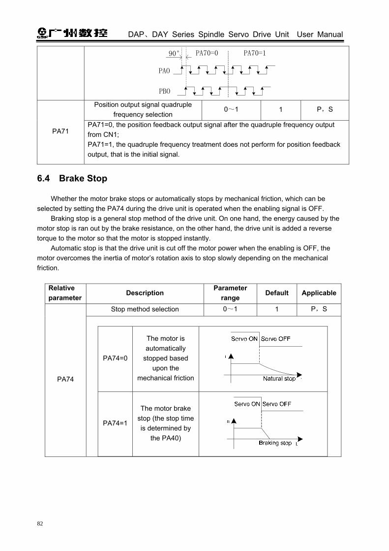
DAP、DAY Series Spindle Servo Drive Unit User Manual
82
PAO
PBO
PA70=0 PA70=190°
Position output signal quadruple
frequency selection 0~1 1 P,S
PA71 PA71=0, the position feedback output signal after the quadruple frequency output from CN1; PA71=1, the quadruple frequency treatment does not perform for position feedback output, that is the initial signal.
6.4 Brake Stop
Whether the motor brake stops or automatically stops by mechanical friction, which can be selected by setting the PA74 during the drive unit is operated when the enabling signal is OFF.
Braking stop is a general stop method of the drive unit. On one hand, the energy caused by the motor stop is ran out by the brake resistance, on the other hand, the drive unit is added a reverse torque to the motor so that the motor is stopped instantly.
Automatic stop is that the drive unit is cut off the motor power when the enabling is OFF, the motor overcomes the inertia of motor’s rotation axis to stop slowly depending on the mechanical friction.
Relative parameter
Description Parameter
range Default Applicable
Stop method selection 0~1 1 P,S
PA74
PA74=0
The motor is automatically
stopped based upon the
mechanical friction
PA74=1
The motor brake stop (the stop time is determined by
the PA40)

Chapter Six Function Debugging
83
6.5 Function Debugging of the Position Mode
6.5.1 Electronic Gear Ratio of Position Commands
When the mechanical speed gear is controlled, the “electronic gear function” can be set the motor movement equals to the input command to an optional value by adjusting the servo parameter, regardless of the deceleration ratio of the machine and the resolution of the encoder.
Relative parameter
Description Unit Parameter
range Default Applicable
PA12 Position pulse command multiple coefficient
1~32767 1 P
PA13 Position pulse command frequency-division coefficient
1~32767 1 P
It is very convenient to match the pulse sources by setting the parameters PA12 and PA13 so that a good distinguishability can be gained for the users (mm/pulse).
Actual load speed = command pulse speed × G × mechanical deceleration rate The least actual load shift = the least command pulse stroke × G × mechanical deceleration rate
When the electronic gear ratio G is not 1, the remainder may induce in the gear ratio division operation, in this case, the position error may occur, the maximum error is the least rotation amount of the motor (the least distinguishability).
The operation of position electronic gear ratio is as follows:
G: Electronic gear ratio, the recommended range is 50501
≤≤ G
C: The resolution of the motor encoder; L:Screw lead (mm); ZM: Gear number of the screw terminal (in the case of the deceleration cabinet). ZD: Gear number of the motor terminal; δ: The system’s least output command unit (mm/pulse); I: Command shift (mm); S: Actual shift (mm); CR: Instruction control unit command multiple coefficient; CD: Instruction control unit command frequency-division coefficient.
[For example]: The machine system is 980TD, its motor is directly connected with X axis screw
G=PA12PA13
=ZMZDL
4CI CRδ CD
S

DAP、DAY Series Spindle Servo Drive Unit User Manual
84
(6mm lead), the motor encoder resolution is 1024, and the command multiple and frequency-division coefficient are not considered, instead of calculating the electronic gear ratio of the drive unit, the following description is the solution:
Solution: the motor is connected directly to the X axis, in this case, the ZM: ZD=1; usually, S =1 I, the command shift is equal to the actual shift; on the other hand, the least output command unit of 980TD system X axis, the δ is equal to 0.0005mm when the radius programme is performed, the formula is shown below:
The parameter PA12 is set to 128, and PA13 is set to 375.
6.5.2 Position Arrival Signal
PAR (CN1-5) is position arrival signal in the position mode. The remain pulse in the position error counter is less than or equal to the setting value of PA16, the drive unit is regarded as the position has been arrived, in this case, this signal is conducted with the common terminal COM-.
Relative parameter
Description Unit Parameter
range Default Applicable
Position arrival range Pulse 0~30000 20 P
PA16
When the remaining pulse amount within the position error counter is less than or equal to the PA16 set value, the drive unit is regarded that the position has been arrived, the position arrival signal PAR is ON, otherwise, it is OFF.
Fig. 6-5
Relative
parameter Description Unit
Parameter range
Default Applicable
Position error check range
×100 pulse
0~999 400 P
PA17 When the position mode is operated and the counter value of the position error counter exceeds PA17 parameter value, the servo unit excess error alarm may occur. (Refer to the Section 8.2 for Err-4 troubleshooting)

Chapter Six Function Debugging
85
6.6 Function Debugging in the Mode of Speed
6.6.1 Orientation Function
Positioning function: It is very necessary to change or measure the tool, the orientation can be rapidly and accurately performed based on the position feedback signal of the motor encoder or that of the 2nd position encoder, and stopped at the preset position (the stop position of the motor rotation shaft or the one of the spindle), which is called the orientation function. The drive unit positioning function composes of the single point positioning and multiple-point positioning.
Orientation accuracy: The orientation accuracy is indicated by the least orientation angle error θ when the orientation axis is performed, the following formula is shown below:
Formula 1――
C: Position feedback encoder resolution 4C: Positioning encoder pulse number after quadruple frequency
The orientation center may be deviated an angle θ from positively or reversely in an actual position, the drive unit orientation can be accurated to 2θ at least.
In the orientation application, the least arc length of an orientation axis connected with the spindle, or the chord length of the least arc is indicated an orientation accuracy. For example, the turning machine, its orientation drilling is performed at the external circle of the round workpiece; the tool-setting is performed between machining center and spindle for the milling machine. In this case, the orientation accuracy depends not only on the motor (or the spindle) encoder resolution, but on the orientation circle diameter, refer to the following formula: Formula 2―― D: Orientation circle diameter δ1: The orientation accuracy is indicated based upon chord length of the orientation circle It also can be performed using the following one: Formula 3―― δ2: The orientating accuracy is indicated based upon chord length of the orientation circle
θ=CC
oo 903604
= Positioning
center
θ
Positioning center
Dθδ 1
δ 1
Positioning center
Dθδ 2
δ 22πD
=δC4
2D sinδ = C
90°1

DAP、DAY Series Spindle Servo Drive Unit User Manual
86
We can draw a conclusion from formulae 2 and 3; the orientation of drive unit can be accurately calculated to 2δ 1 or to the 2δ 2 at least.
For example:
Fig. 6-10
Drill on the round workpiece external circle with 200mm diameter; it is recommended that the drilling orientation error should be less than 50μm, how many encoders of resolution s should be calculated in this case.
We should be calculated in terms of the chord length. (Less than 50μm), the drive unit should be
indicated as ≤25μm, refer to the following formula 3:
Then: C ≥ 6280
The encoder resolution should be equal to or more than 6280 for guaranteeing the drilling position error less than 50μm.
Relative parameter
Name Unit Parameter
range Default Applicable
PA55 Orientation speed r/min 5~1000 100 S
Position window in orientating
Pulse 0~100 2 S
PA56
The drive unit enters the position loop control after the orientation function is performed, and the motor rotor axis (or the spindle) searches and exact stops at an orientation position in terms of its speed. A slight vibration may occur at the instant of the motor stop because of the closed-loop condition of the position loop.
πD≥
δC
4
πD≥δ
C4

Chapter Six Function Debugging
87
The completion of the orientation is regarded as performed when the error of the motor vibration is within the orientation window; the COIN (CN1-21) orientation completion signal is conducted with the common terminal COM-. The orientation completion signal output may unsteady due to the motor vibration, if the set value is excessively low, and then the orientation may fail.
Relative
parameter Description
Parameter range
Default Unit Applicable
The direction of orientation selection
0~2 0 S
PA57
PA57=0, The orientation speed is CCW when the motor starts CCW, and the orientation speed is CW when the motor starts CW;
Explanation: When the curve A indicates the operation speed is more than the orientation speed,
decelerate the operation speed to the orientation speed, till to 0 after the orientation position is found, the orientation is executed. In the same way, curve B indicates that the operation speed is less than the orientation speed; accelerate the operation speed to the orientation speed, and then decelerated to 0 after the orientation position is found, the orientation is completed.
PA57=1, all of the motors are positioned CCW regardless of the operating direction of the motor.
n(r/ min)Running speed
Orientation speed
Orientation star0
n(r/ min)
T(S)
0
T(S)
CCW Orientation
The completion of orientation
Orientation speed
Running speed
The completion of orientation
All of the motors are positioned CW no matter what the operating direction is when PA57=2;
n(r/ min)Run speed
Orientation speed
The completion of orientationOrientation start
A
0
n(r/ min)
Run speed
Orientation speed
The completion of orientation
Orientation start
B
0
n(r/min )
Run speed
Orientation speed
0
The completion of orientationOrientation start
A
n(r/ min)
T(S)Run speed
Orientation speed
The completion of orientationOrientation start
B
0
T(S)
T(S)
T(S)
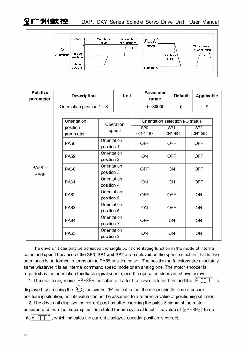
DAP、DAY Series Spindle Servo Drive Unit User Manual
88
Relative parameter
Description Unit Parameter
range Default Applicable
Orientation position 1~8 0~30000 0 S
PA58~PA65
Orientation selection I/O status Orientation
position parameter
Operation speed SP0
(CN1-10)SP1
(CN1-40) SP2
(CN1-26)
PA58 Orientation position 1
OFF OFF OFF
PA59 Orientation position 2
ON OFF OFF
PA60 Orientation position 3
OFF ON OFF
PA61 Orientation position 4
ON ON OFF
PA62 Orientation position 5
OFF OFF ON
PA63 Orientation position 6
ON OFF ON
PA64 Orientation position 7
OFF ON ON
PA65 Orientation position 8
ON ON ON
The drive unit can only be achieved the single point orientating function in the mode of internal command speed because of the SP0, SP1 and SP2 are employed on the speed selection; that is, the orientation is performed in terms of the PA58 positioning set. The positioning functions are absolutely same whatever it is an internal command speed mode or an analog one. The motor encoder is regarded as the orientation feedback signal source, and the operation steps are shown below:
1. The monitoring menu is called out after the power is turned on, and the is
displayed by pressing the ; the symbol “E” indicates that the motor spindle is on a unsure positioning situation, and its value can not be assumed to a reference value of positioning situation.
2. The drive unit displays the correct position after checking the pulse Z signal of the motor encoder, and then the motor spindle is rotated for one cycle at least. The value of turns
into , which indicates the current displayed encoder position is correct.

Chapter Six Function Debugging
89
The motor rotates for one cycle, the rotation axis can be performed manually when the motor is disabled, a rotation spindle also can be commanded for a low speed
3. Adjust the motor axis or the conjoint spindle to the orientation point step by step, record the position that the is being displayed, and then write in the PA58, this parameter value is the orientation position 1 after saving. 4. User can adjust eight positioning points consecutively, the correct positions of these positioning points are registered in PA58~PA65 one by one, in this case, the multiple points can be positioned. 5. The SON signal is set to ON, (the SFR signal ON is simultaneously used in the mode of the analog command speed), the positioning start signal STAO always keep ON regardless of the operation of the motor. The motor is rotated firstly at the positioning speed set by PA55, and then immediately kept at the positioning place after its positioning point is searched, simultaneously, the completion signal of positioning COIN is conducted with COM-. 6. The tool-change operation is performed after the CNC device is received COIN, the positioning start signal must be reserved at all times during tool change is performed, and the orientation start signal must be cancelled after the operation is specified. After that, the other operations can be performed.
The operation procedure of the 2nd position input signal is regarded as the orientation position feedback signal resource is similar as the above-mentioned, and the rest of steps are same other than the previous three steps:
1. After the power is turned on, call out the monitor menu , display by
pressing , symbol ‘E’ indicates that the spindle is on the incorrect position and its value can not be assumed to the positioning reference value.
2. Rotate the spindle for one revolution at least, the drive unit can automatically search the
proper position of the 2nd position encoder, after this position is found, the value of
becomes , which means that the position of the current encoder is correct.
3. Adjust the spindle to an orientation point gradually, record the displayed position, write to PA58 for saving, this parameter value is the orientation 1.
4. The motor encoder is performed the orientation operation steps 4~5 repeatedly, and then the orientation can be executed.
The whole orientation process time sequence is shown below:
Spindle orientation time sequence A (The motor is operating)

DAP、DAY Series Spindle Servo Drive Unit User Manual
90
Fig. 6-11
Spindle orientation time sequence B (The motor is free or at zero speed)
Orientation speed
t≥0.5s
0 speed
Drive enabling (SON)
Orientation start signal (STAO)
Speed (n)
The completion of orientation (COIN)
Fig. 6-12
6.6.2 Analog Command Adjustment
The following three parameters should be adjusted when the speed command is inconsistent with the actual motor speed: Parameter Description Parameter range Default Applicable
Analog 10V for the motor speed 0~15500 6000 S
PA42
The input command VCMD voltage range is set, the factory value has been set to 10V corresponding to 6000r/min. For example: if PA42=5000,
10V command corresponding to motor run 5000r/min, 5V command corresponding to motor run 2500r/min, 1V command corresponding to motor run 500r/min.

Chapter Six Function Debugging
91
Analog command zero draft
compensation -1000~1000 0 S
PA44
The motor still rotates in a low speed sometimes when the command voltage is 0V, because it is caused by the“offset (=command offset)” from the instruction control unit or external command voltage with the small voltage (mV). Adjust this “offset” to “0V”, the motor is then stopped.
Analog slope adjustment coefficient
-1000~1000 0 S
PA47
The relation between the analog command and speed is treated as a hatched area (Refer to the figure at the right side), PA47 can adjust its slope of this diagonal .When the deviation is performed between the actual speed and the specified analog command, and the deviation can be modified by adjusting this parameter, ensure that the analog command has no null before adjusting. (Compensation can be performed adjusting PA44)

DAP、DAY Series Spindle Servo Drive Unit User Manual
92
-6000r/min
10V-10V
6000r/min
PA47<00
PA47>0
PA47=0
It is recommended that the adjust sequence of the analog amount is shown below: 1. It is necessary to confirm the value of PA42; generally, its value is set to the top speed of the
motor; 2. Then, the motor stops after the “offset amount” is modified to “0V” by adjusting PA44. 3. Lastly, several speed commands are specified separately, such as 1000r/min, 3000r/min and
6000r/min, whether the motor’s speed slope is consistent with the command based upon the motor speed displays by LED, reduce the error by adjusting PA47.
6.6.3 Speed Arrival Signal
The speed mode of SAR (CN1-5) is speed arrival signal. The actual speed = the [command speed × (100-PA31)% ~ command speed × (100+
PA31)%], this signal is connected with the common terminal COM-. Relative
parameter Description Unit
Parameter range
Default Applicable
PA31 Speed arrival valid range % 1~100 10 S
For example: Set PA31 to 10, which indicates 10% of a command speed. When the actual speed is accelerated or decelerated to 900r/min~1100r/min and the specified speed has been set to 1000r/min, the speed arrival signal (SAR) is output. Refer to the following figure:
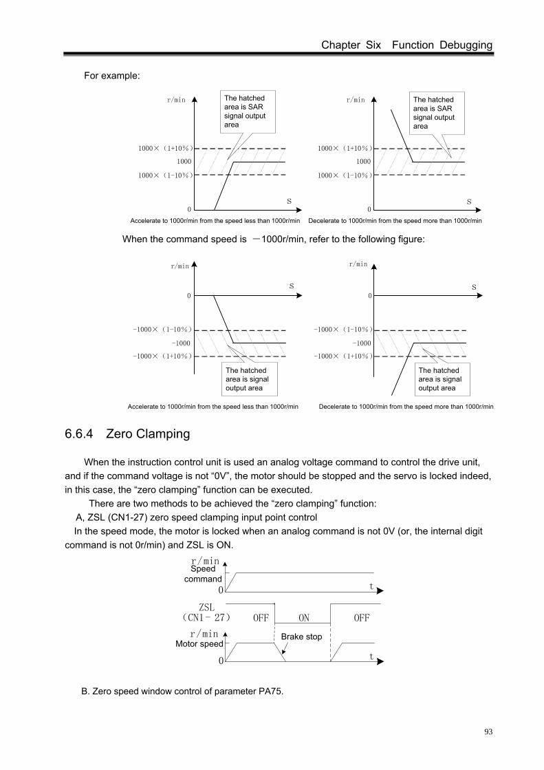
Chapter Six Function Debugging
93
For example:
When the command speed is -1000r/min, refer to the following figure:
6.6.4 Zero Clamping
When the instruction control unit is used an analog voltage command to control the drive unit, and if the command voltage is not “0V”, the motor should be stopped and the servo is locked indeed, in this case, the “zero clamping” function can be executed.
There are two methods to be achieved the “zero clamping” function: A, ZSL (CN1-27) zero speed clamping input point control In the speed mode, the motor is locked when an analog command is not 0V (or, the internal digit
command is not 0r/min) and ZSL is ON.
Brake stop
(CN1- 27) OFF ON
r/min
0 t
OFFZSL
0 t
Speed command
Motor speed
r/min
B. Zero speed window control of parameter PA75.
1000
1000×(1-10%)
1000×(1+10%)
r/min
1000
1000×(1-10%)
1000×(1+10%)
r/min
0 0
Accelerate to 1000r/min from the speed less than 1000r/min Decelerate to 1000r/min from the speed more than 1000r/min
The hatched area is SAR signal output area
The hatched area is SAR signal output area
s s
Decelerate to 1000r/min from the speed more than 1000r/minAccelerate to 1000r/min from the speed less than 1000r/min
The hatched area is signal output area
The hatched area is signal output area
-1000
-1000×(1-10%)
-1000×(1+10%)
r/min
-1000
-1000×(1-10%)
-1000×(1+10%)
r/min
0 0
s s

DAP、DAY Series Spindle Servo Drive Unit User Manual
94
Parameter number
Description Unit Parameter
range Default Applicable
PA75 Analog command zero
speed window r/min 0~1000 0 S
When analog command voltage corresponding① to the speed is less than or equal to the set value in zero speed window, the motor speed is clamped at zero speed.
This command zero speed window is absolute v② alue to suit the positive or negative analog command voltage.
6.6.5 Speed Command Electronic Gear Ratio
“Speed command electronic gear function”, can be converted the analog commands into the maximum command voltage 10V by adjusting the parameters, regardless of the maximum command voltage offered by the instruction control unit.
Relative parameter
Description Unit Parameter
range Default Applicable
PA35 Analog command multiple
coefficient 1~32767 1 S
PA36 Analog command
frequency-division coefficient 1~32767 1 S
It is very convenient to match each analog voltage source by setting the parameters PA35 and PA36. That is, when the maximum command voltage given by the instruction control unit is not 10V, the maximum command voltage can be converted into 10V by setting the parameters PA35 and PA36.
[For example]: the instruction control unit is specified 6V analog voltage command, how to set the value of PA35 or PA36 :
can be computed .
Relative parameter
Description Unit Parameter
range Default Applicable
PA42 Analog 10 corresponding to the motor’s speed
r/min 0~15500 6000 S

Chapter Six Function Debugging
95
In the case of the drive ratio between the motor axis and the loading axis is not 1:1, the PA42 is set to match the loading axis maximum speed corresponding to 10V.
[For example]: The maximum spindle speed of one lathe is 3000r/min, the drive ratio is 3:5, calculate the setting of PA42:
Then:
ZM: Gear amount of the spindle terminal; ZD: Gear amount of motor terminal; It can be calculated:
Therefore, the PA42 should be set to 5000r/min.

DAP、DAY Series Spindle Servo Drive Unit User Manual
96
CHAPTER SEVEN PARAMETER
7.1 Parameter Table P: Position control S: Speed control Parameter No. Description Setting range Default Unit Applicable Parameter
position PA0 Password 0~9999 315 P,S 4.4 PA1 Motor type code 0~30 0 P,S
PA2 Software version (read only) 105 P,S
PA3 ※ Monitoring setting at the initial power 0~24 0 P,S 4.3
PA4 Working selection 0~5 1 P,S Chapter Five
PA5 Speed loop proportional gain 10~3000 700 Hz P,S 6.1.1
PA6 Speed loop integral coefficient 1~3000 5 P,S 6.1.1
PA7 Reserved
PA8 Speed feedback filtering coefficient 50~1000 100 P,S 6.1.1
PA9 Position loop proportional gain 20~1000 40 1/s P 6.1.1
PA10 Position loop feedforward gain 0~100 0 % P 6.1.1
PA11 Position feedforward filtering coefficient 1~1200 300 Hz P 6.1.1
PA12 Position pulse command multiple coefficient 1~32767 1 P 6.5.1
PA13 Position pulse command frequency-division coefficient
1~32767 1 P 6.5.1
PA14 Position command mode selection 0~2 0 P 3.4.2
PA15 Position command direction reverse 0~1 0 P 6.2
PA16 Position arrival range 0~30000 20 Pulse P 6.5.2
PA17 Position excess error check range 0~999 400 P 6.5.2
PA18 Position excess error check invalid 0~1 0 P 8.2(Err4)
PA19 Reserved PA20 Reserved
PA21 JOG run speed -6000~6000 300 r/min S 5.1.2
PA22 Speed command selection 0~1 1 S 5.2
PA23 Maximum speed limit 0~15500 6000 r/min P,S PA24 Internal speed 1 -20000~20000 1000 r/min S 5.2.2
PA25 Internal speed 2 -20000~20000 -500 r/min S 5.2.2
PA26 Internal speed 3 -20000~20000 2000 r/min S 5.2.2

Chapter Seven Parameter
97
(Continued) Parameter No. Description Set range Default Unit Applicable Reference
position
PA27 Internal speed 4 -20000~20000 -3000 r/min S 5.2.2
PA28 Internal speed 5 -20000~20000 5000 r/min S 5.2.2
PA29 Internal speed 6 -20000~20000 3000 r/min S 5.2.2
PA30 Internal speed 7 -20000~20000 10 r/min S 5.2.2
PA31 Speed arrival valid range 1~100 10 % S 6.6.3
PA32 Zero sped output valid range 0~100 10 r/min P,S 3.4.3
PA33 Forced enabling 0~1 0 P,S 3.4.2
PA34 The maximum drive capability 10~300 300 % P,S 8.3
PA35 Analog command multiple coefficient 1~32767 1 S 6.6.5
PA36 Analog command frequency-division coefficient
1~32767 1 S 6.6.5
PA37 Reserved PA38 Reserved
PA39 Acceleration time constant 0~10000 50 1ms S 5.2.1
PA40 Deceleration time constant 0~10000 100 1ms S 5.2.1
PA41 Reserved
PA42 Analog 10 corresponding to the motor’s speed 0~15500 6000 r/min S 5.2.1
PA43 Analog command filtering coefficient 1~600 100 S 6.1.1
PA44 User analog command null drift compensation
-1000~1000 0 S 6.6.2
PA45 Analog command reverse/CCW, CW rotation start input reverse
0~1 0 S 5.2.1
PA46 Analog input working selection 0~1 0 S 5.2.1
PA47 Analog slope adjust coefficient
-1000~1000 0 S 6.6.2
PA48 Motor type 1 1 P,S
PA49 ※ Motor encoder resolution 128~8000 1024 P,S
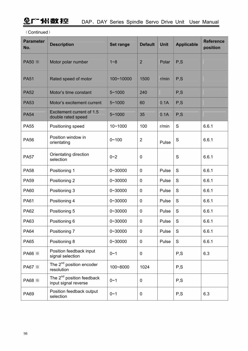
DAP、DAY Series Spindle Servo Drive Unit User Manual
98
(Continued)
Parameter No.
Description Set range Default Unit Applicable Reference position
PA50 ※ Motor polar number 1~8 2 Polar P,S
PA51 Rated speed of motor 100~10000 1500 r/min P,S
PA52 Motor’s time constant 5~1000 240 P,S
PA53 Motor’s excitement current 5~1000 60 0.1A P,S
PA54 Excitement current of 1.5 double rated speed 5~1000 35 0.1A P,S
PA55 Positioning speed 10~1000 100 r/min S 6.6.1
PA56 Position window in orientating 0~100 2
Pulse S 6.6.1
PA57 Orientating direction selection 0~2 0 S 6.6.1
PA58 Positioning 1 0~30000 0 Pulse S 6.6.1
PA59 Positioning 2 0~30000 0 Pulse S 6.6.1
PA60 Positioning 3 0~30000 0 Pulse S 6.6.1
PA61 Positioning 4 0~30000 0 Pulse S 6.6.1
PA62 Positioning 5 0~30000 0 Pulse S 6.6.1
PA63 Positioning 6 0~30000 0 Pulse S 6.6.1
PA64 Positioning 7 0~30000 0 Pulse S 6.6.1
PA65 Positioning 8 0~30000 0 Pulse S 6.6.1
PA66 ※ Position feedback input signal selection 0~1 0 P,S 6.3
PA67 ※ The 2nd position encoder resolution 100~8000 1024 P,S
PA68 ※ The 2nd position feedback input signal reverse 0~1 0 P,S
PA69 Position feedback output selection 0~1 0 P,S 6.3

Chapter Seven Parameter
99
(Continued)
Parameter No.
Description Set range Default Unit Applicable Reference position
PA70 Position feedback output reverse
0~1 0 P,S 6.3
PA71 Position signal output quadruple frequency selection
0~1 1 P,S 6.3
PA72 Alarm output reverse 0~1 0 P,S 3.4.3
PA73 Motor over-heat alarm shielding
0~1 0 P,S
PA74 Brake function selection 0~1 1 P,S 6.4
PA75 Analog command zero speed window
0~1000 0 r/min S 6.6.4
PA76 Shifting from the position mode to the speed
0~1 0 P,S 5.4
PA77 Shifting the orientation position in speed/position mode
0~30000 0 Pulse P,S 5.4
PA78
10V analog command corresponds to the maximum speed when the 2nd speed loop gain is valid.
0~15500 6000 r/min S 6.1.2
PA79 The 2nd speed loop proportional gain
10~3000 700 Hz S 6.1.2
PA80 The 2nd speed loop integral coefficient
1~3000 5 S 6.1.2
1. The shaded parameters in the parameter table, its default set are related to the motor type, the different defaults are determined on different motors.
2. The parameters with the symbol “ ” in ※ the parameter table, which can be taken effect after the modified parameters are written and the power is turned on.

DAP、DAY Series Spindle Servo Drive Unit User Manual
100
7.2 Details for the Parameter Significance Relative
parameter Description
Parameter range
Default Unit Applicable
Parameter password modification
0~9999 315 P,S PA0
PA0=315, parameters can be modified other than PA1 and PA2, it is very necessary to set the PA0=385 if the PA1 is needed to modify.
Motor type code 0~30 0 P,S
PA1 Set the type code corresponding to the drive motor refer to the Motor Type Code List (Appendix A), then recover the default value corresponding parameters to the motor. This parameter has been set based on the matched motor before delivery. Normally, User can not modify the parameters by himself.
PA2 Software version (Read only) \ 105 P,S
Monitoring setting at the initial power
0~24 0 P,S
Parameter value
Monitoring displays at the initial
power
Explanation Parameter
value
Monitoring displays at the initial
power
Explanation
PA3=0 Motor speed
PA3=13 To be developed
PA3=1 Current motor position lower 5-bit (pulse)
PA3=14
Motor encoder pulse Z absolute position
PA3=2
Current motor position higher 5-bit (×100000 pulse)
PA3=15 Input terminal state
PA3=3 Position command lower 5-bit (pulse)
PA3=16 Output terminal state
PA3=4 Position command higher 5-bit (×100000 pulse)
PA3=17 Encoder feedback signal
PA3=5 Position error lower 5-bit (pulse)
PA3= 18 Drive unit working state
PA3=6 Position error higher 5-bit (×100000 pulse)
PA3=19 Alarm display
PA3=7 To be developed
PA3= 20 DC bus voltage
PA3=8 Motor current
PA3=21 Software version
PA3=9 Analog command corresponding to the speed
PA3=22 Hardware version
PA3=10 Current control mode
PA3=23
Spindle encoder pulse Z absolute position
PA3=11 Position command pulse frequency
PA3=24 To be developed
PA3 ※
PA3=12 Speed command

Chapter Seven Parameter
101
Working mode selection 0~5 1 P,S
PA4
PA4=0: Position mode; The motor’s rotating direction and angle are specified by the digit pulse or the data
communication, the drive unit controls the motor’s rotor to rotate a corresponding angle based on the specified direction. The rotation angle (position) and speed can be controlled. PA4=1: Speed mode;
The rotation direction and speed of the motor can be specified by the analog voltage or the data communication, the drive unit controls the rotor of motor in terms of the specified direction and speed, this working not only improves the rapid response capability of the motor, but enhances the anti-interference capability of the motor operation speed. PA4=2: Manual operation;
In the menu of Sr-, the acceleration or deceleration can be performed by ‘ or ’. PA4=3: JOG operation;
In the menu of Jr-, the JOG speed set by the parameter, which is rotated CCW or CW by the
‘ or ’ separately. PA4=4: To be developed; PA4=5: Speed/position mode. In this method, the input point VP (speed/position shift) is set to OFF, the drive unit will be operated at the speed mode after enabling; when the input point VP is set to ON, the drive unit is firstly performed the orientation, then shifted to the position mode till VPO signal (speed/position state) has been output.
Speed loop proportional gain 10~3000 700 Hz P,S
PA5 The more the speed loop proportional gain is, the bigger the servo rigid is, but the vibration (An abnormal voice occurs in the motor) may occur during starting or stopping when it is excessively bigger, the less the value is, the slower the corresponding the motor responds.
Speed loop integral coefficient 1~3000 3 P,S
PA6 The more the speed loop integral coefficient is, the faster the system response is, but the system may instable when the setting value is excessive, even the vibration may occur; the less the value is, the slower the response is. Set the value as bigger as possible when the system does not cause a vibration.
Speed feedback filtering coefficient
50~1000 100 P,S
PA8
The bigger the speed feedback filter coefficient is, the faster the speed feedback response is. The motor may generated big electromagnetic noise if the setting value is excessive; the less the setting value is, the slower the speed feedback response is; the vibration may issue, because the setting value is reduced and the speed wave is enlarged.
Position loop proportional gain 20~1000 40 1/s P
PA9 The bigger the speed loop proportional gain is, the faster the response of the position command is, the bigger the rigid is. If the value is excessive, the position overrun caused a vibration when the motor is started or stopped; the less the setting value is, the slower the response is, the bigger the followed error is.

DAP、DAY Series Spindle Servo Drive Unit User Manual
102
(Continued) Relative
parameter Description
Parameter range
Default Unit Applicable
Position loop feed forward gain
0~100 0 % P
PA10 The position loop feedforward gain is debugged the speed loop with the speed information specified with the position command, the more the set value is, the less the follow error is, the less the followed error is. The instantaneous overshooting and vibration of the motor may occur due to the set value is excessively big.
Position loop feedforward filtering coefficient
1~1200 300 Hz P
PA11
The position forward feedback filter coefficient is used for the smooth treatment for position command feedforward control, the bigger the setting value is, the faster response for the step speed command is, and the position overrun or vibration can be restricted further when the command speed is suddenly changed; the less the setting value is in the mutation speed, the less obvious the effect of the feed forward is, the smaller the vibration caused by the feedforward is.
Position pulse command multiple coefficient
1~32767 1 P PA12
Refer to the Section 6.5.1 for electronic gear ratio Position pulse command
frequency-division coefficient 1~32767 1 P
PA13 Refer to the Section 6.5.1 for electronic gear ratio
Position command mode selection
0~2 0 P
PA14 PA14=0: pulse + direction PA14=1: CCW pulse/CW pulse; PA14=2: Two-phase orthogonal pulse input; Refer to the Section 3.4.2 for signal input explanation.
Position command direction reverse
0~1 0 P PA15
PA15=0: Maintaining the original command direction; PA15=1: The input pulse command direction is reverse.
Position arrival range 0~30000 20 Pulse P
PA16
The number of remaining pulse within the position error counter (DP – EPO of the menu displays) is less than or equal to PA16 set value, the servo unit is regarded as the position has been arrived, the position arrival signal PAR outputs ON or OFF.
Motor speed
Command speed
Position error
PAR(CN1-5)
PA16
OFFON ON

Chapter Seven Parameter
103
(Continued) Relative
parameter Description
Parameter range
Default Unit Applicable
Position excess-error check range
0~999 400 ×100 pulse
P
PA17 When the count value of position error counter exceeds the parameter value of PA17, and when the position mode is performed, an alarm in the servo unit excess-error may occur. (Refer to the Section 8.2 for the Err-4 troubleshootings)
The position excess-error check is disabled
0~1 0 P PA18
PA18=0: check the position excess error alarm; PA18=1: do not check the position excess error alarm.
JOG operation speed set -6000~6000 300 r/min S PA21 The operation speed is set under (Jr) JOG operation method, and its operation
method is determined by PA4.
Speed command selection 0~1 1 S
PA22 When PA22=1, the speed command is external analog voltage command (-10V+10V or 0~10V). Whe PA22=0, the speed command is set by parameters PA24~PA30, and they are selected by the state of input terminals SP0, SP1 and SP2.
The maximum speed limitation
0~15500 6000 r/min S PA23
Motor’s maximum speed is restricted in PA23.
Internal speed 1~7 -20000~20000 1000 r/min S
PA24~PA30
I/O state speed selection Digital
command default
Operation speed SP0
(CN1-10)SP1
(CN1-40) SP2
(CN1-26)
0 r/min OFF OFF OFF PA24=1000 Internal speed 1 ON OFF OFF
PA25=-500 Internal speed 2 OFF ON OFF PA26=2000 Internal speed 3 ON ON OFF
PA27=-3000 Internal speed 4 OFF OFF ON PA28=5000 Internal speed 5 ON OFF ON
PA29=3000 Internal speed 6 OFF ON ON PA30=10 Internal speed 7 ON ON ON
Speed arrival valid range 1~100 10 % S
PA31 In the speed mode, when the actual speed is equal to the [command speed × (100-PA31)%~command speed× (100+PA31)%], the SAR (CN1-5) signal is connected with the common terminal COM-. (Refer to the section 6.6.3)

DAP、DAY Series Spindle Servo Drive Unit User Manual
104
(Continued) Relative
parameter Description
Parameter range
Default Unit Applicable
Zero speed output valid range 0~100 10 r/min P,S
PA32
Zero speed (ZSP) signal is output when the actual speed is less than or equal to the zero speed output valid range.
Enforced enabling 0~1 0 P,S
PA33 PA33=1, enforce enabling (do not check SON (CN1-24) signal); PA33=0, the enabling signal is specified by SON (CN1-24). (Refer to the section 3.4.2)
The maximum drive unit 0~300 300 % P,S
PA34 This parameter is to be set a motor’s maximum drive current.
Motor’s maximum drive current= motor’s rated current ×PA34% When the set value exceeds the top output current of the drive unit, and the current restriction may work for drive unit IMP modul.
PA35 Analog command multiple coefficient (refer to PA36)
1~32767 1 S
Analog command frequency-division coefficient
1~32767 1 S
PA36
It is very convenient to match the various analog command voltage resources by the setting of the parameters PA35 and P36. Namely, when the maximum command voltage specified by the instruction control unit is not 10V, the maximum command voltage 10V can be switched by the setting of PA35 and PA36. For example: up to 6V analog command is specified by the instruction control unit.
Then: can be calculated .
PA39 Acceleration time constant (refer to PA40)
1~10000 50 ms S

Chapter Seven Parameter
105
(Continued) Relative
parameter Description
Parameter range
Default Unit Applicable
Deceleration time constant 1~10000 100 ms S
PA40
The acceleration/deceleration time constant is only valid in the speed mode. Acceleration time is the needed time to set the motor from zero speed to the rated speed, refer to the fig. t1; Deceleration time is the needed time to set the motor from the rated speed to the zero speed, refer to the fig. t2. Then: the actual acceleration time of the motor=
command speed/rated speed×PA39; the actual deceleration time of the motor= command speed/rated speed×PA40; Note: The actual time may more than the setting time if the setting time is much smaller and the actual acceleration/deceleration is limited by the maximum acceleration/deceleration capability of the drive unit.
PA42 Analog 10 corresponding to
the motor’s speed 0~15500 6000 r/min S
Analog command filtering coefficient
1~600 100 S
PA43 The smaller the analog command filter cut-off frequency setting is, the stronger the capability of restriction of interference signal is. If the value is excessively small, the speed command response is slower. The bigger the value is, the worse the restriction capability of the signal interference is, the faster the speed command responds.
Analog command null drift compensation
-1000~1000 0 S
PA44
When the command voltage is “0V”, the motor still rotates slightly sometimes. It is caused by the instruction control unit or external command voltage with the slight speed (mV) “offset (=command offset)”. The motor may then stop after adjusting PA44 and the “offset value” is modified into “0V”.
PA45
Analog command reverse/CCW, rotation start input is reverse CCW and CW (refer to PA46)
0~1 0 S

DAP、DAY Series Spindle Servo Drive Unit User Manual
106
(Continued) Relative
parameter Description
Parameter range
Default Unit Applicable
Analog input working selection 0~1 0 S
PA46
External analog voltage command range is-10V~+10V;
PA45=0
The voltage command is positive, and the motor starts CCW; The voltage command is negative, and the motor starts CW; PA46=0
PA45=1
The voltage command is positive, and the motor starts CW; The voltage command is negative, and the motor starts CCW;
External analog voltage command range is 0~+10V.
PA45=0 SFR is ON, and the motor starts CCW; SFV is ON, and the motor starts CW; PA46=1
PA45=1 SFR is ON, and the motor starts CW; SRV is ON, and the motor starts CCW;
Analog slope adjustment coefficient
-1000~1000 0 S
PA47
The relation between the analog command and the speed are treated as a hatched area. (Refer to the figure at the right side), PA47 can adjust its slope of this diagonal. When the deviation is performed between the actual speed and the specified analog command, and the deviation can be modified by adjusting this parameter, ensure that the analog command has no null drift before adjusting. (Compensation can be performed by adjusting PA44)
PA48 Motor type (read) \ 1 P,S
PA49 ※ Motor’s encoder resolution 128~8000 1024 P,S
PA50 ※ Motor polar number 1~8 2 Dipolar P,S
PA51 The rated speed of motor 100~10000 1500 r/min P,S
PA49, PA50 or PA51 can be set the basis parameters of the motor, the setting value can be gained from the nameplate of the spindle motor.
Note: The unit of PA50 is the number of pole-pairs of the motor. (one dipolar = 2 polar)
PA52 Motor time constant 5~1000 240 P,S
PA53 Motor excitement current 5~1000 60 0.1A P,S

Chapter Seven Parameter
107
(Continued) Relative
parameter Description
Parameter range
Default Unit Applicable
PA54 Excitement current in 1.5
times rated speed 5~1000 35 0.1A P,S
Parameters, such as PA52, PA53 and PA54 are set in terms of the configuration motor from the factory, and the user does not need to adjust.
PA55 Orientating speed 5~1000 100 r/min S
Orientating position window 0~100 2 pulse S
PA56
The drive unit enters the position-loop control after the orientation is started; the motor rotating shaft (or spindle) is firstly searched and exactly stops at an orientation place. A slight vibration may occur while the motor stops because of the closed-loop adjustment of the position loop. The orientation is regarded as completion when the error of the motor vibration is within the orientation window, and the COIN (CN1-21) orientating completion signal is conducted with the common terminal COM-.
If the set value is excessively small, the completion of orientating signal output may unsteady due to the vibration of motor, even the orientation may fail.
Orientating direction function 0~2 0 S
PA57
PA57=0, the direction of the orientation speed is CCW when the motor starts CCW, and that of the orientation speed is CW when the motor starts CW;
Explanation: Curve A indicates that the run speed is more than the orientation one. Accelerate to
the orientation speed firstly, till to 0 after the orientation is found, the orientation is then
n(r/min)Run speed
Orientation speed
The completion of orientationOrientation start
A
0
n(r/min)
Run speed
Orientation speed
The completion of orientation
Orientation start
B
0
n(r/ min )
Run speed
Orientation speed
0
The completion of orientationOrientation start
A
n(r/min)
T(S)Run speed
Orientation speed
The completion of orientationOrientation start
B
0
T(S)
T(S)
T(S)

DAP、DAY Series Spindle Servo Drive Unit User Manual
108
executed. Same, curve B indicates that the run speed is less than the orientation one. Accelerate to the orientation speed firstly, and then decelerate to 0 after the orientation is found, the orientation is then completed.
PA57=1, the motors are all orientated at CCW orientation speed regardless of its operating direction;
PA57=2, the motors are all orientated at CW orientation speed regardless of its operating direction;
Orientating position 1~8 0~30000 0 Pulse S
PA58~PA65
I/O state in the orientation selection Orientating
position parameter
Operation speed SP0
(CN1-10)SP1
(CN1-40) SP2
(CN1-26)
PA58 Orientating position 1
OFF OFF OFF
PA59 Orientating position 2
ON OFF OFF
PA60 Orientating position 3
OFF ON OFF
PA61 Orientating position 4
ON ON OFF
PA62 Orientating position 5
OFF OFF ON
PA63 Orientating position 6
ON OFF ON
PA64 Orientating position 7
OFF ON ON
PA65 Orientating position 8
ON ON ON
Position feedback input signal selection
0~1 0 P,S
PA66 ※ PA66=1, the motor encoder selection signal is regarded as the position feedback input signal; PA66=0, the 2nd position input signal selection is treated as the position feedback input signal, in this case, the CN3 does not connect the 2nd position encoder feedback signal. The drive unit Err-24 malfunction may occur.

Chapter Seven Parameter
109
(Continued) Relative
parameter Description
Parameter range
Default Unit Applicable
PA67 ※ The 2nd position encoder
resolution 100~8000 1024 P,S
The 2nd position feedback input signal reverse
0~1 0 P,S
PA68 ※
PA68=0: Maintain the initial pulse phase relation between the 2nd position input signals SCA and SCB; PA68=1, the phase relation between SCA and SCB is reverse.
Position feedback output signal selection
0~1 0 P,S
PA69 PA69=0, the motor encoder signal is regarded as the position output signal; PA69=1, the 2nd position input signal is regarded as the position output signal, in this case, the CN3 does not connect the 2nd position encoder feedback signal. The drive unit Err-24 malfunction may issue.
Position feedback output signal reverse
0~1 0 P,S
PA70
PA70=0, in the CN1, the phase relation between the position feedback output signals PAO and PBO is invariable; PA70=1, the phase relation between the position feedback output signals PA and PB is reverse, it is shown below:
PAO
PBO
PA70=0 PA70=190°
Position feedback output signal quadruple frequency
selection 0~1 1 P,S
PA71 PA71=0, a position feedback output signal is displayed after CN1 is output quadruple frequency; PA71=1, a position feedback output signal does not treated as a quadruple frequency; that is, it is indicated as the original signal.
Alarm output reverse 0~1 0 P,S
PA72 PA72=0, ALM signal output terminal is conducted with COM- when the drive unit alarms. PA72=1, ALM signal output terminal is cut off with COM- when the drive unit alarms.The motor overheating alarm
shields 0~1 0 P,S
PA73 PA73=0, The motor overheating alarm is enabled; PA73=1, shield the motor overheating alarm.

DAP、DAY Series Spindle Servo Drive Unit User Manual
110
(Continued) Relative
parameter Description
Parameter range
Default Unit Applicable
Stop mode selection 0~1 1 P,S PA74 PA74=0, the motor is naturally stopped depended on the mechanical friction;
PA74=1, the motor brake stops (the stop time is determined by PA40) Analog command zero speed
window 0~1000 0 r/min S
PA75
① When the speed corresponding to the analog command voltage is less than or equal to the zero speed window set value, the motor spindle is clamped at the zero speed. ② This command zero speed window is an absolute value, and it is suitable to the positive/negative analog command voltage.
Select the mode when the position mode is switched to the speed mode
0~1 0 P/S
PA76 In the mode of speed/position, the transition mode is selected from position control shifts to the speed control. PA76=0: When VP signal is skipped to OFF, the speed control is being shifted after the position command of control operation is performed. PA76=1: When VP signal is skipped to OFF, the speed control is immediately shifted regardless of whether the position command is completed. Speed/position shift reference point position
0~30000 0 P/S
PA77 When the drive unit is switched from the speed control to the position control, search the position speed set by PA55, then it exactly stops at the reference position set by PA77 till the position command occurs. (Refer to the section 6.6.1 orientating function for the whole process) The top speed corresponding
to 10V analog command when the 2nd speed loop gain
is enabled.
0~15500 6000 r/min S PA78
TAP (CN1-41) is enabled when it is ON, and its function is same as PA42.
The 2nd proportional gain of the speed loop
10~3000 700 Hz S PA79
TAP (CN1-41) is valid when it is ON, and its function is same as that of PA5.
The 2nd integral coefficient of the speed loop
1~3000 5 S PA80
TAP (CN1-41) is valid when it is ON, and its function is same as that of PA6.
n
-10V 10V
Zero speed window(0~1000r/min)
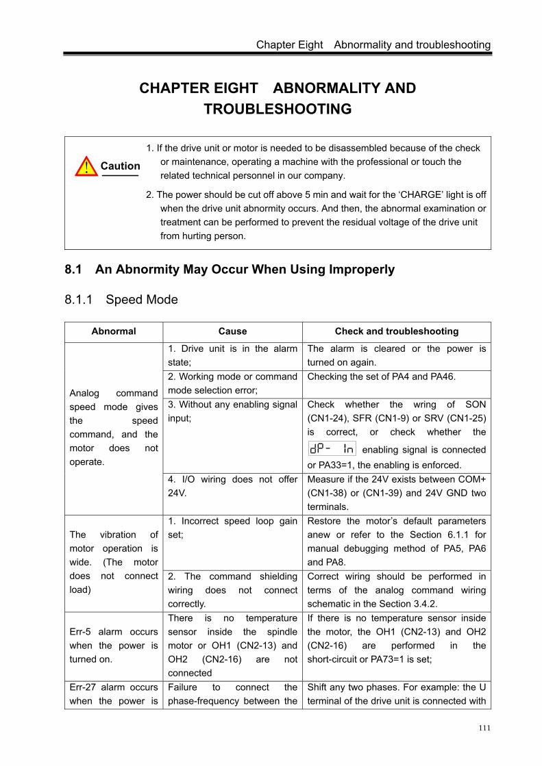
Chapter Eight Abnormality and troubleshooting
111
CHAPTER EIGHT ABNORMALITY AND TROUBLESHOOTING
1. If the drive unit or motor is needed to be disassembled because of the check or maintenance, operating a machine with the professional or touch the related technical personnel in our company.
2. The power should be cut off above 5 min and wait for the ‘CHARGE’ light is off when the drive unit abnormity occurs. And then, the abnormal examination or treatment can be performed to prevent the residual voltage of the drive unit from hurting person.
8.1 An Abnormity May Occur When Using Improperly
8.1.1 Speed Mode
Abnormal Cause Check and troubleshooting
1. Drive unit is in the alarm state;
The alarm is cleared or the power is turned on again.
2. Working mode or command mode selection error;
Checking the set of PA4 and PA46.
3. Without any enabling signal input;
Check whether the wring of SON (CN1-24), SFR (CN1-9) or SRV (CN1-25) is correct, or check whether the
enabling signal is connected or PA33=1, the enabling is enforced.
Analog command speed mode gives the speed command, and the motor does not operate.
4. I/O wiring does not offer 24V.
Measure if the 24V exists between COM+ (CN1-38) or (CN1-39) and 24V GND two terminals.
1. Incorrect speed loop gain set;
Restore the motor’s default parameters anew or refer to the Section 6.1.1 for manual debugging method of PA5, PA6 and PA8.
The vibration of motor operation is wide. (The motor does not connect load)
2. The command shielding wiring does not connect correctly.
Correct wiring should be performed in terms of the analog command wiring schematic in the Section 3.4.2.
Err-5 alarm occurs when the power is turned on.
There is no temperature sensor inside the spindle motor or OH1 (CN2-13) and OH2 (CN2-16) are not connected
If there is no temperature sensor inside the motor, the OH1 (CN2-13) and OH2 (CN2-16) are performed in the short-circuit or PA73=1 is set;
Err-27 alarm occurs when the power is
Failure to connect the phase-frequency between the
Shift any two phases. For example: the U terminal of the drive unit is connected with
! Caution
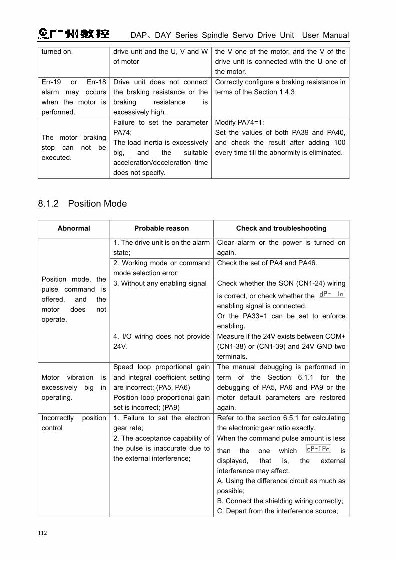
DAP、DAY Series Spindle Servo Drive Unit User Manual
112
turned on. drive unit and the U, V and W of motor
the V one of the motor, and the V of the drive unit is connected with the U one of the motor.
Err-19 or Err-18 alarm may occurs when the motor is performed.
Drive unit does not connect the braking resistance or the braking resistance is excessively high.
Correctly configure a braking resistance in terms of the Section 1.4.3
The motor braking stop can not be executed.
Failure to set the parameter PA74; The load inertia is excessively big, and the suitable acceleration/deceleration time does not specify.
Modify PA74=1; Set the values of both PA39 and PA40, and check the result after adding 100 every time till the abnormity is eliminated.
8.1.2 Position Mode
Abnormal Probable reason Check and troubleshooting
1. The drive unit is on the alarm state;
Clear alarm or the power is turned on again.
2. Working mode or command mode selection error;
Check the set of PA4 and PA46.
3. Without any enabling signal Check whether the SON (CN1-24) wiring
is correct, or check whether the enabling signal is connected. Or the PA33=1 can be set to enforce enabling.
Position mode, the pulse command is offered, and the motor does not operate.
4. I/O wiring does not provide 24V.
Measure if the 24V exists between COM+ (CN1-38) or (CN1-39) and 24V GND two terminals.
Motor vibration is excessively big in operating.
Speed loop proportional gain and integral coefficient setting are incorrect; (PA5, PA6) Position loop proportional gain set is incorrect; (PA9)
The manual debugging is performed in term of the Section 6.1.1 for the debugging of PA5, PA6 and PA9 or the motor default parameters are restored again.
1. Failure to set the electron gear rate;
Refer to the section 6.5.1 for calculating the electronic gear ratio exactly.
Incorrectly position control
2. The acceptance capability of the pulse is inaccurate due to the external interference;
When the command pulse amount is less
than the one which is displayed, that is, the external interference may affect. A. Using the difference circuit as much as possible; B. Connect the shielding wiring correctly;C. Depart from the interference source;

Chapter Eight Abnormality and troubleshooting
113
D. A step RC circuit is added to perform a filtering.
3. When the pulse command is input by adopting single-ended drive connection, the current-limiting resistance does not connect in series;
Refer to the Section 3.4.2 for position command wiring schematic to connect wiring.
4. Mechanical connecting malfunction
When the pulse number is equal to the
one displayed, and it equals to
the pulse number displayed by after the electronic gear ratio is converted. Check whether the connection of the machine is loose or distorted
The load waves greatly wide during starting or stopping.
The load inertia is bigger; the corresponding acceleration/deceleration time of the instruction control unit command is excessively small.
Increasing the acceleration/deceleration time of the instruction control unit position command so that the start or stop of motor is smooth and steady.
8.2 The Significance and Troubleshooting of Alarm Codes
The drive unit has many protective functions, and the motor stops operating when the
malfunction is checked after the power is turned on; the alarm code is displayed on the
operation panel. It can be also entered the menu to check the current alarm code. The user can check the related content based on the alarm code to understand the cause of the malfunction and remove it.
Alarm No.
Significance Main reason Troubleshooting
1. Encoder feedback signal abnormal;
Check the connection of the motor or the 2nd position encoder with the signal wire
2. In the speed mode, acceleration/deceleration time constant is excessively small, so that the speed overshoot is excessively big;
Enlarge the acceleration time PA39 and the deceleration time PA40.
3. PA23 (the maximum speed limit) set value is excessively small or PA49 (the motor encoder resolution) set is less than the actual one;
The PA23 is correctly set based upon the motor’s nameplate.
Err-1
Spindle motor speed exceeds the setting value (Refer to the PA23 parameter for the maximum speed limit)
4. Control panel malfunction. Change the drive unit.
Err-2 Main circuit DC bus voltage is
1. Brake resistance does not connect or gets damaged;
Check the brake resistance and its connection
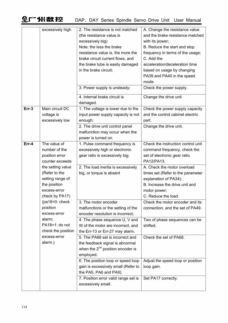
DAP、DAY Series Spindle Servo Drive Unit User Manual
114
2. The resistance is not matched (the resistance value is excessively big) Note: the less the brake resistance value is, the more the brake circuit current flows, and the brake tube is easily damaged in the brake circuit;
A. Change the resistance value and the brake resistance matched with its power; B. Reduce the start and stop frequency in terms of the usage; C. Add the acceleration/deceleration time based on usage by changing PA39 and PA40 in the speed mode.
3. Power supply is unsteady; Check the power supply.
excessively high
4. Internal brake circuit is damaged.
Change the drive unit
1. The voltage is lower due to the input power supply capacity is not enough;
Check the power supply capacity and the control cabinet electric part.
Err-3 Main circuit DC voltage is excessively low
2. The drive unit control panel malfunction may occur when the power is turned on.
Change the drive unit.
1. Pulse command frequency is excessively high or electronic gear ratio is excessively big;
Check the instruction control unit command frequency, check the set of electronic gear ratio PA12/PA13.
2. The load inertia is excessively big, or torque is absent
A. Check the motor overload times set (Refer to the parameter explanation of PA34); B. Increase the drive unit and motor power; C. Reduce the load.
3. The motor encoder malfunctions or the setting of the encoder resolution is incorrect;
Check the motor encoder and its connection, and the set of PA49.
4. The phase sequence U, V and W of the motor are incorrect, and the Err-13 or Err-27 may alarm.
Two of phase sequences can be shifted.
5. The PA68 set is incorrect and the feedback signal is abnormal when the 2nd position encoder is employed.
Check the set of PA68.
6. The position loop or speed loop gain is excessively small (Refer to the PA5, PA6 and PA9);
Adjust the speed loop or position loop gain.
Err-4
The value of number of the position error counter exceeds the setting value (Refer to the setting range of the position excess-error check by PA17) (pa18=0: check position excess-error alarm; PA18=1: do not check the position excess-error alarm.)
7. Position error valid range set is excessively small.
Set PA17 correctly.

Chapter Eight Abnormality and troubleshooting
115
(Continued) Alarm
No. Significance Main cause Troubleshooting
1. There is no temperature device inside the motor;
Set PA73=1 shields the motor overheat alarm.
2. Overloading causes the motor is seriously hot;
Increase the drive unit or motor power, or reducing the load.
3. The start/stop frequency is excessive high in the case of overloading;
Reduce the start/stop frequency, improve the cooling condition of the motor
4. The temperature check equipment of the motor is being damaged, or the internal motor is trouble or the cooling fan is being damaged;
Change spindle servo motor.
Err-5 The alarm may occur due to the motor’s high temperature, and the drive unit has been checked the over-heat alarm signal output from the motor (PA73=0: check the motor over-heat alarm; PA73=1: do not check the position error alarm.)
5. The motor temperature check signal is normal, and the drive unit control panel malfunctions
Change the drive unit
1. Position command electronic gear ratio is excessively big;
Check the parameters set of both PA12 and PA13.
Err-8 Position error counter flow
2. Command pulse input is abnormal.
Check the instruction control unit command pulse frequency.
1. The motor encoder signal wiring is defective or incorrect;
Check the welding between the connector and the signal wire.
2. The motor encoder signal feedback cable is excessively long causing the signal voltage is lower;
Cut the cable (within 30m)
3. The motor encoder is damaged; Change the motor or its encoder.
Err-9 The motor encoder signal feedback abnormity
4. Drive unit control panel malfunction
Change the drive unit.
1. The drive unit enabling does not issue yet when the power is turned on, and it is difficult to eliminate; A. The drive unit control panel malfunction; B. The wiring terminal of the braking resistance and the ground is in the short circuit.
Change the drive unit if it is cause A; Check and connect the braking resistance correctly if it is cause B.
Err-11 IPM module is disabled inside the drive unit.
2. The alarm occurs when the drive unit does not enable after the power is turned on, and it can be eliminated after the power is turned on again.
It caused by the bad grounding or external interference. Check the grounding and search the interference resource, then depart or shield from the interference resource.

DAP、DAY Series Spindle Servo Drive Unit User Manual
116
(Continued) Alarm
No. Significance Main cause Troubleshooting
3. The alarm occurs when the drive unit is enabled after the power is turned on, and it can not be eliminated; A. The motor power supply cable is short-circuited among U, V and W, or or it is short-circuited U, V, W and PE;
Change the motor’s cable or the motor if it is cause A; Change the drive unit if it is cause B.
Err-11 IPM module is disabled inside the drive unit.
4. It may occur when the motor is started or stopped, and it can be eliminated after the power is turned on again. A. The motor default parameter set by the drive unit is incorrect B. The load inertia is bigger, and the command acceleration rate is bigger when starting or stopping;
Restore the motor’s default parameters again if it is the reason A. (Refer to the Section 4.4); add the acceleration or deceleration time of a command and reduce the command acceleration rate if it is the reason B, or reduce the load inertia;
1. Long time overcurrent of the motor;
Reduce the load.
2. The parameter setting is incorrect, the motor may has vibration or abnormal noise;
Adjust the capability parameter related with the motor (Refer to explanation of PA5, PA6, PAA8, PA9 and PA34)
3. The PA49 setting value is more than the resolution of the actual encoder;
Set the encoder resolution of the motor correctly.
Err-13 The overload alarms during the motor operation
4. Wrong wiring of U, V and W. The operation after the power is turned on which is similar as that of the Err-27 alarm.
Change any two of the phases
Err-16 The overload alarm may occur during the motor is operated.
The motor loading operates for a long time, and it is longer than that of the Err-13.
A. Reduce the load; B. Change the drive device with higher power.
1. Input high-power for long time; Input the required power for satisfying the drive unit.
Err-17 Excessively long braking time
2. The brake resistance is bigger; the internal DC voltage is raised due to the power can not released immediately during brake.
Change the correct brake resistance, and refer to the Section 1.4.3 for details.

Chapter Eight Abnormality and troubleshooting
117
(Continued) Alarm
No. Significance Main cause Troubleshooting
1. Brake circuit malfunction; Change the drive unit. Err-18 There is a brake start signal without a brake feedback
2. The value of brake resistance is excessive.
Measure the value of brake resistance by the multimeter to confirm the better one.
1. Brake circuit malfunction; Change the drive unit. Err-19 The voltage of DC BUS is too high, but the brake is not performed.
2. The brake resistance is an open-circuit or it is not connected.
Check the connection of the brake resistance.
1. Fail to read the data from EEPROM for the drive unit when the power is turned on;
Restore the motor default parameter again, and refer to the Section 4.4 for details.
Err-20
The EEPROM malfunction alarms inside the drive unit when the power is turned on.
2. The EEPROM CMOS chip or the PCB malfunction.
Change the servo drive unit.
1. One of the input power wiring phases is cut off, or the phase was missed;
A. Check the input power wiring, connect it again; B. Check the input three-phase power.
Err-21 The alarm is issued when the input power R, S or T is missed.
2. The drive unit power inputs a malfunction circuit.
Change the drive unit.
Err-23 Current error is excessively big
1. The current checks the circuit malfunction; 2. Current sensor is damaged; 3. Power voltage malfunction control
Change the drive unit
1. The 2nd position encoder feedback signal does not connect, and the parameter PA66 is set to 1;
Modify PA66=0. Err-24 Detect that the 2nd position input signal of CN3 interface is abnormal 2. The spindle encoder
feedback signal is abnormal. (It is same reason as that of alarm Err-9)
A. Check the 2nd position encoder signal connection, welding and plug; B. The excessively long encoder cable may cause the signal voltage is lower, cut the cable within 30m.
1. Pulse Z signal can not be checked
Feedback input signal wire is checked.
Err-25 Failure to the drive unit orientation 2. The corresponding
parameter set is incorrect or the gain set is excessively big due to the inertia is bigger;
Check the related motor’s parameter values PA49, PA66 and PA67. The related gain parameters are PA5, PA6, PA8
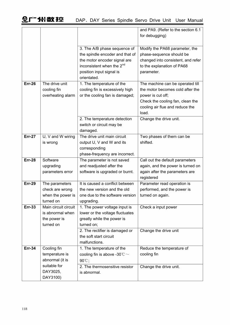
DAP、DAY Series Spindle Servo Drive Unit User Manual
118
and PA9. (Refer to the section 6.1 for debugging)
3. The A/B phase sequence of the spindle encoder and that of the motor encoder signal are inconsistent when the 2nd position input signal is orientated.
Modify the PA68 parameter, the phase-sequence should be changed into consistent, and refer to the explanation of PA68 parameter.
1. The temperature of the cooling fin is excessively high or the cooling fan is damaged;
The machine can be operated till the motor becomes cold after the power is cut off; Check the cooling fan, clean the cooling air flue and reduce the load.
Err-26 The drive unit cooling fin overheating alarm
2. The temperature detection switch or circuit may be damaged.
Change the drive unit.
Err-27 U, V and W wiring is wrong
The drive unit main circuit output U, V and W and its corresponding phase-frequency are incorrect.
Two phases of them can be shifted.
Err-28 Software upgrading parameters error
The parameter is not saved and readjusted after the software is upgraded or burnt.
Call out the default parameters again, and the power is turned on again after the parameters are registered
Err-29 The parameters check are wrong when the power is turned on
It is caused a conflict between the new version and the old one due to the software version upgrading.
Parameter read operation is performed, and the power is turned on again.
1. The power voltage input is lower or the voltage fluctuates greatly while the power is turned on;
Check a input power Err-33 Main circuit circuit is abnormal when the power is turned on
2. The rectifier is damaged or the soft start circuit malfunctions.
Change the drive unit
1. The temperature of the cooling fin is above -30~
90 ;
Reduce the temperature of cooling fin
Err-34 Cooling fin temperature is abnormal (it is suitable for DAY3025, DAY3100)
2. The thermosensitive resistor is abnormal.
Change the drive unit.
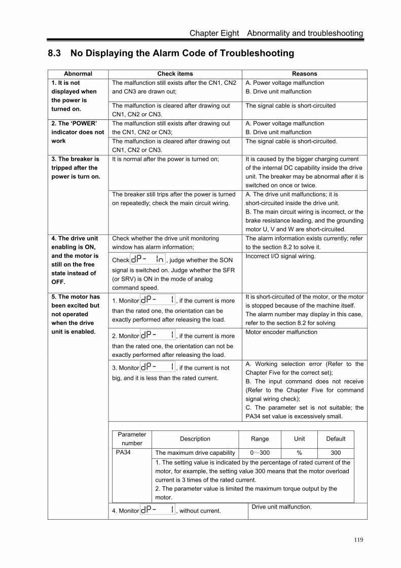
Chapter Eight Abnormality and troubleshooting
119
8.3 No Displaying the Alarm Code of Troubleshooting
Abnormal Check items Reasons The malfunction still exists after the CN1, CN2 and CN3 are drawn out;
A. Power voltage malfunction B. Drive unit malfunction
1. It is not displayed when the power is turned on. The malfunction is cleared after drawing out
CN1, CN2 or CN3. The signal cable is short-circuited
The malfunction still exists after drawing out the CN1, CN2 or CN3;
A. Power voltage malfunction B. Drive unit malfunction
2. The ‘POWER’ indicator does not work The malfunction is cleared after drawing out
CN1, CN2 or CN3. The signal cable is short-circuited.
It is normal after the power is turned on; It is caused by the bigger charging current of the internal DC capability inside the drive unit. The breaker may be abnormal after it is switched on once or twice.
3. The breaker is tripped after the power is turn on.
The breaker still trips after the power is turned on repeatedly; check the main circuit wiring.
A. The drive unit malfunctions; it is short-circuited inside the drive unit. B. The main circuit wiring is incorrect, or the brake resistance leading, and the grounding motor U, V and W are short-circuited.
Check whether the drive unit monitoring window has alarm information;
The alarm information exists currently; refer to the section 8.2 to solve it.
4. The drive unit enabling is ON, and the motor is still on the free state instead of OFF.
Check , judge whether the SON signal is switched on. Judge whether the SFR (or SRV) is ON in the mode of analog command speed.
Incorrect I/O signal wiring.
1. Monitor , if the current is more
than the rated one, the orientation can be exactly performed after releasing the load.
It is short-circuited of the motor, or the motor is stopped because of the machine itself. The alarm number may display in this case, refer to the section 8.2 for solving
2. Monitor , if the current is more
than the rated one, the orientation can not be exactly performed after releasing the load.
Motor encoder malfunction
3. Monitor , if the current is not
big, and it is less than the rated current.
A. Working selection error (Refer to the Chapter Five for the correct set); B. The input command does not receive (Refer to the Chapter Five for command signal wiring check); C. The parameter set is not suitable; the PA34 set value is excessively small.
Parameter
number Description Range Unit Default
The maximum drive capability 0~300 % 300 PA34
1. The setting value is indicated by the percentage of rated current of the motor, for example, the setting value 300 means that the motor overload current is 3 times of the rated current. 2. The parameter value is limited the maximum torque output by the motor.
5. The motor has been excited but not operated when the drive unit is enabled.
4. Monitor , without current. Drive unit malfunction.

DAP、DAY Series Spindle Servo Drive Unit User Manual
120
(Continued) Malfunction Examination procedure Cause
1. Check whether the command is correct
Monitor in the position mode, and judge the position command;
Monitor in the speed mode, and judge the analog command;
Instruction command malfunction
2. Compare < Refer to the motor type code table of appendix II>, check the setting of PA1, and perform to restore the operation of the value by default after the correct setting is performed.
Incorrect motor parameters by default.
6. Spindle motor can only operate at low speed instead of high speed.
3. Perform the orientation; the spindle motor can not be orientated exactly.
Motor’s encoder malfunction.
The motor can be run stably in the mode of manual. The input command is interrupted strongly. It is necessary to keep away from the interference resource and deal with the shielding cable.
7. The spindle motor operates unstably and the speed fluctuation is excessively high. The motor still run unstably in the mode of manual,
and the speed fluctuation is excessively high. A. The motor encoder is malfunctioned, change the motor. B. Wrong parameter setting. Set the motor’s parameter by default again, especially, the setting of the dipolar and the resolution of encoder.
8. The speed overshoot is excessively large when the start or stop is performed, and the motor waves obviously.
1. Check whether the acceleration/deceleration time of the motor is too short when it starts/stops. 2. Check whether the parameter setting of speed loop or the position loop proportional integral is set excessive. (Refer to the Section 6.1 for the parameter setting)
The bigger load inertia.
1. Check the cooling fan The fan is damaged, or the power of fan is connected incorrectly.
2. Check the cooling flue Cooling air flue is jammed by something.
3. Check circumstance temperature If the ambient temperature is too high, enlarge or improve the cooling device.
4. Check whether the load is overload. Reduce the load if it is excessive
9. Spindle motor is overheat
5. Check the motor’s type code parameter. Motor’s default parameter is incorrect.
1. Check whether the setting of the speed loop and the position loop parameter are correct.
Motor’s default parameter is incorrect.
2. Check whether the analog command or the position command has strongly interference;
The input command is interrupted strongly. It is necessary to keep away from the interference resource and deal with the shielding cable.
3. Release the load, and check whether the load is resisted.
The load is resisted with the, foreign matter, or distorted.
10. Spindle motor has abnormal noise.
4. The stop is freely performed at high speed, check whether the motor still has noise.
A. The screw looses in the fixed motor B. Malfunction occurs inside the motor.
11. The motor still rotates even if speed command is 0V.
Check the analog command null compensation parameter PA44.
The null compensation does not perform.
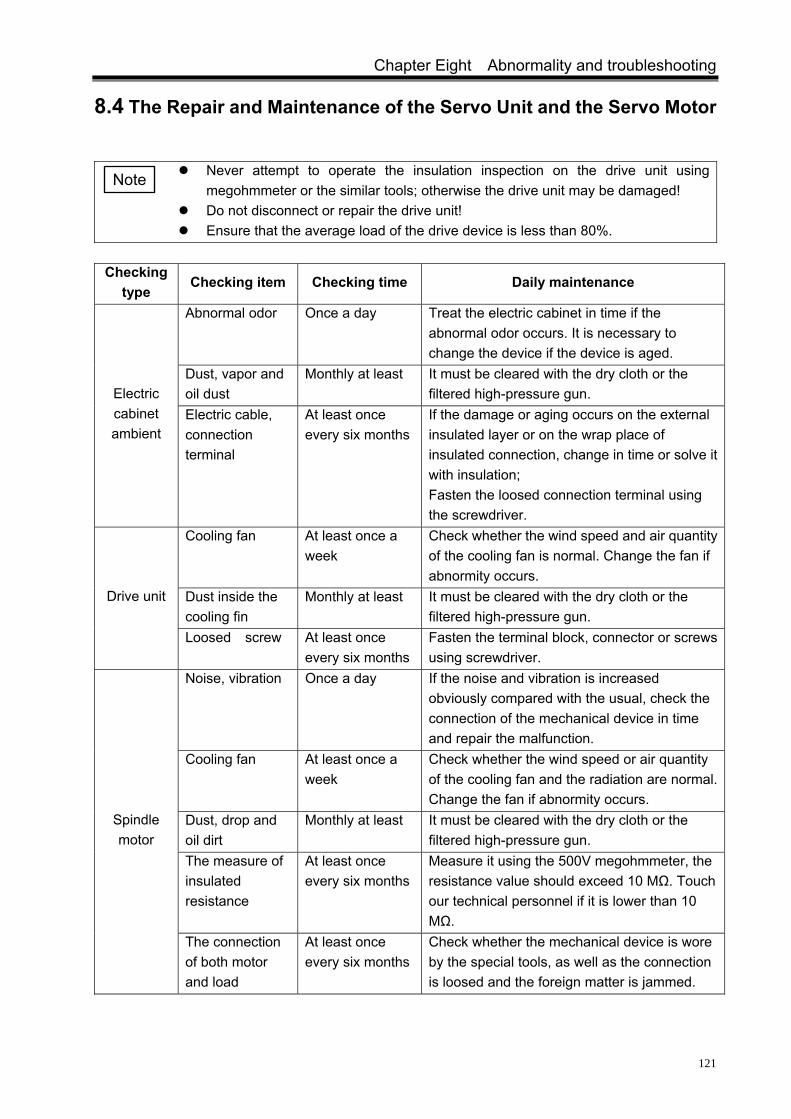
Chapter Eight Abnormality and troubleshooting
121
8.4 The Repair and Maintenance of the Servo Unit and the Servo Motor
Never attempt to operate the insulation inspection on the drive unit using
megohmmeter or the similar tools; otherwise the drive unit may be damaged! Do not disconnect or repair the drive unit! Ensure that the average load of the drive device is less than 80%.
Checking
type Checking item Checking time Daily maintenance
Abnormal odor Once a day Treat the electric cabinet in time if the abnormal odor occurs. It is necessary to change the device if the device is aged.
Dust, vapor and oil dust
Monthly at least It must be cleared with the dry cloth or the filtered high-pressure gun. Electric
cabinet ambient
Electric cable, connection terminal
At least once every six months
If the damage or aging occurs on the external insulated layer or on the wrap place of insulated connection, change in time or solve it with insulation; Fasten the loosed connection terminal using the screwdriver.
Cooling fan At least once a week
Check whether the wind speed and air quantity of the cooling fan is normal. Change the fan if abnormity occurs.
Dust inside the cooling fin
Monthly at least It must be cleared with the dry cloth or the filtered high-pressure gun.
Drive unit
Loosed screw At least once every six months
Fasten the terminal block, connector or screws using screwdriver.
Noise, vibration Once a day If the noise and vibration is increased obviously compared with the usual, check the connection of the mechanical device in time and repair the malfunction.
Cooling fan At least once a week
Check whether the wind speed or air quantity of the cooling fan and the radiation are normal. Change the fan if abnormity occurs.
Dust, drop and oil dirt
Monthly at least It must be cleared with the dry cloth or the filtered high-pressure gun.
The measure of insulated resistance
At least once every six months
Measure it using the 500V megohmmeter, the resistance value should exceed 10 MΩ. Touch our technical personnel if it is lower than 10 MΩ.
Spindle motor
The connection of both motor and load
At least once every six months
Check whether the mechanical device is wore by the special tools, as well as the connection is loosed and the foreign matter is jammed.
Note

DAP、DAY Series Spindle Servo Drive Unit User Manual
122
Appendix A The Comparison Table of Type Parameters and Spindle Motors
PA1 parameter
Spindle motor type and technical parameter
0 GM7101-4SB6,3.7kW, 6000r/min,0.02kg.m2
1 GM7103-4SB6,5.5kW, 6000r/min, 0.02kg.m2
2 GM7105-4SB6,7.5kW, 6000r/min, 0.032kg.m2
3 GM7131-4SB6,11kW, 6000r/min, 0.076kg.m2
4 GM7103-4SC6,7.5kW, 9000r/min, 0.02kg.m2
5 GM7100-4SB6,2.2kW, 6000r/min,0.015kg.m2
6 GM7109-4SB6,11kW, 6000r/min, 0.037kg.m2
7
8
9 YPNC-50-2.2-B, 2.2kW,380V, 6000r/min, 5.1A, 14 N·m
10 YPNC-50-3.7-B, 3.7kW,380V, 6000r/min, 8.0A, 24 N·m
11 YPNC-50-5.5-B, 5.5kW,380V, 6000r/min, 11.8A, 36 N·m
12 YPNC-50-7.5-B, 7.5kW,380V, 6000r/min, 16.0A, 49 N·m
13 YPNC-50-11-B, 11kW, 380V, 6000r/min, 21.3A, 72 N·m
14 YPNC-50-15-B, 15kW, 380V, 6000r/min, 33.0A, 98 N·m
15
16
17
18
19
20 ZJY208-2.2-B5(B3) 6.3A 380V, 6000r/min
21 ZJY208-2.2-B5(B3) 9.3A 380V, 6000r/min
22 ZJY208-3.7-B5(B3) 9.1A 380V, 6000r/min
23 ZJY208-5.5-B5(B3) 13.2A 380V, 6000r/min
24 ZJY208-7.5-B5(B3) 17.3A 380V, 6000r/min
25 ZJY265-7.5-B5(B3) 18A 380V, 6000r/min
26 ZJY265-11-B5(B3) 26A 380V, 6000r/min
27 ZJY265-15-B5 (B3) 35A 380V, 6000r/min

Appendix
123
Appendix B The Selection of Peripheral Equipment
B.1 Breaker and Contactor (Required Equipment)
The breaker and contactor should be installed between the input power and spindle serve unit. The breaker and contactor are regarded not only as the switch of drive unit, but also as the protective function of the power.
The breaker is a protective switch for cutting the malfunction circuit automatically, which has the protective function, for instance, circuit overload, short circuit or UV (under-voltage). The drive unit, itself has an overload capability of 150% and 30min. to play its overload capability, it is recommended that the user use the breaker with the protection of power distribution.
The power ON or OFF of the drive device with the electric protection is controlled by the circuit to install the AC contactor can cut off the power of the drive device immediately when the system is troubled, effectively guarantee the further expansion of the fault.
The users can configure the technical data by themselves in terms of the following table: Motor power matched with
the drive unit (kW) 2.2 3.7 5.5 7.5 11 15
Breaker rated current (A) 25 25 32 32 50 63
AC contactor (A) 9 12 18 25 32 40
B.2 Three-phase AC Filter (Recommended Equipment)
The three-phase AC filter is a passive low-pass filter, the filter frequency is among 10kHz~30MHz, which restrains the high-frequency noise interference issued from the power terminal of drive unit. Generally, it is not needed to install. When the high-frequency noise interference generated from the drive unit is affected the normal work of other devices during the user operates, it is better to install it.
Users can automatically configure the technical data based upon the following table: Motor power matched with
the drive unit (kW) 2.2 3.7 5.5 7.5 11 15
Three-phase AC filter rated current (A)
10 20 20 30 40 50
Three-phase AC filter rated voltage (V)
380/440 380/440 380/440 380/440 380/440 380/440
Three-phase AC filter inductor (mH)
≈2.8 ≈1.6 ≈1.6 ≈0.9 ≈1.1 ≈0.6
Three-phase AC filter leakage current (mA)
≤2 ≤2 ≤2 ≤2 ≤2 ≤3
The cautions of the filter installation are shown below: The filter metal shell must be on a perfect contact with the electric cabinet, the grounding should
be well connected; The filter input line and output line must be spaced, but must not paralleled to prevent the
reduction of the filter’s capability;

DAP、DAY Series Spindle Servo Drive Unit User Manual
124
The filter should be installed at the entrance of the device power, and the filter input wiring length should be shortened inside the cabinet as much as possible so that the radiate interference is reduced.
B.3 AC Reactor (Recommended Equipment) The AC reactor is connected with the power input terminal for controlling the input current higher
harmonic, it can be prevented the interference from electric net, as well as the harmonic current for polluting the electric net introduced from integrative unit which can be reduced. Generally, the use environment may not install, it is recommended that the AC reactor may be installed for the drive unit in the following working conditions:
1. The matched power of motor is more than 15kW. 2. The three-phase power voltage, its imbalance range is more than 3%. 3. The thyristor current transformer, non-linear load, arc furnace load as well as the
compensation capacity device by shifting with the switches, which are on the same power system. 4. The power factor aside the input must be improved. The selection of AC reactor can be determined on the pressure drop of the prospective reactor
winding for each phase; generally, the pressure drop is treated as the 2%~4% of the power grid side voltage. It is not essential to evaluate a large value of the pressure drop of the serial reactor otherwise, the motor torque may occur. In this case, the 4% (8.8V) leading-in voltage should be applied.
Users can configure the technical data by themselves based on the following table:
Three-phase AC lead-in reactor Spindle servo drive unit output
power Rated working voltage Rated
current Inductive range
2.2 kW Three-phase AC 380V/50Hz 8A~10 A 1.0 mH~2.5 mH
3.7 kW Three-phase AC 380V/50 Hz 9A~10 A 1. mH ~2.5 mH
5.5 kW Three-phase AC 380V/50 Hz 13A~15 A 1.0 mH~1.5 mH
7.5 kW Three-phase AC 380V/50 Hz 18A~20 A 0.8 mH~1.2 mH
11 kW Three-phase AC 380V/50 Hz 24A~30 A 0.5 mH~0.8 mH
15 kW Three-phase AC 380V/50 Hz 34A~40 A 0.4 mH~0.6 mH

Appendix
125
Appendix C The Wiring Diagram between the Spindle Servo Drive Unit and CNC System
C.1 The System Wiring Diagram between the Drive Unit and GSK218m
Spindle servo drive unit GSK 218M milling system
XS41
Spindle positive Y2.3Spindle enabling Y2.0
Zero clamping Y2.5Spindle position Y2.1
Spindle zero speed check X4.7
Spindle speed arrival X4.6Spindle positioning
completion X5.0Speed/position shifting
X4.4
4 XCP+4 XCP-4 XDIR+4 XDIR-
9
ZSL
COM+
PULS+PULS-SIGN+
SIGN-
XS33
SFR252427111235
38
20521
14
44
1516117218342283334
7
SRVSON
STAOVP
COM-
ZSPSARCOINVPOALM
VCMD+VCMD-
PAO+PAO-
PBO+
PBO-
PZO+
PZO-
2
24V
Spindle positive Y2.2151514634
6188
9
17
110311412519210
13
Speed/position shifting Y2.70 V
SDALMSVCSCOMA+A-B+B-Z+Z-
XS23
XS45
CN1
Metal shell Metal shell
4×2kΩ/0.5W

DAP、DAY Series Spindle Servo Drive Unit User Manual
126
C.2 The Connection Illustration between the Drive Unit and GSK980TDa
1. GSK 980TDa lathe machine system can be modified the system PLC program based upon
the requirements of the user, so that the signal definition inside the XS39, XS41 and XS42 interface can be changed, the wiring should be changed correspondingly in terms of the above figure. 2. The signal with ‘’ may not connect when the C-axis function is used or the orientation function do not use; the signal with ‘’ may not connect when the C-axis function does not use.3. In order to simplify the wiring, it is recommended to use the deconcentrator MCT04 offered by our company.

Appendix
127
The drive unit connects with GSK980TDa system which is used the method of MCT04 deconcentrator.
Deconcentrator
MC
T04
Spindle servo drive unit
Input 2
Input 1
Output 1
Output 2
Y-axis
X-axis
Encoder
Transducer
MP
G
Com
munication
Z-axis
Note1: The signal interfaces of the drive unit are same, such as the connection cable between CN1
to the CN1 of MCT04 deconcentrator, the XS41 or XS42 of 980TDa system is separately connected to the A/B connection cable of MCT04 deconcentrator. The pin numbers to be used should be connected correspondingly when the cable is being performed.
Note2: The connection between the system XS32 and the XS32 on MCT02 deconcentrator is shown below:

DAP、DAY Series Spindle Servo Drive Unit User Manual
128
XS32XS32
8 PAS
7 *PAS
6 PBS
5 *PBS
4 PCS
3 *PCSPZ- 3
PZ+ 4
PB- 5
PB+ 6
PA- 7
PA+ 8
Metal shell Metal shell
3. The connection of system XS33, XS37 and XS37 on MCT02 deconcentrator is shown below:

Appendix
129
C.3 The Wiring Illustration between Drive Unit and GSK 980TD1(V2)
1. GSK 980TD1(V2) lathe machine system can be modified the system PLC program based upon the requirements of the user, so that the signal definition inside the XS39, XS40 interface can be changed, the wiring should be changed correspondingly in terms of the above figure. 2. The signal with ‘’ may not connect when the C-axis function is used or the orientation function do not use; the signal with ‘’ may not connect when the C-axis function does

DAP、DAY Series Spindle Servo Drive Unit User Manual
130
not use. 3. In order to simplify the wiring, it is recommended to use the deconcentrator MCT02 offered by our company.
The drive unit is connected with GSK 980TD1(V2)wiring, which is used the method of MCT02 deconcentrator:
Note 1: The signal interfaces of the drive unit are same, such as the connection cable between CN1 to the CN1 of MCT02 deconcentrator, the XS40/XS39 of 980TD1 (V2) is separately connected to the XS40/XS39 on MCT02 deconcentrator. The pin numbers to be used should be connected correspondingly when the cable is being performed.
Note 2: The connection of system XS32 and XS32 on MCT02 deconcentrator is shown below:

Appendix
131
XS32XS32
8 PAS
7 *PAS
6 PBS
5 *PBS
4 PCS
3 *PCSPZ- 3
PZ+ 4
PB- 5
PB+ 6
PA- 7
PA+ 8
Metal shell Metal shell 3. The connection of system XS33, XS37 and XS37 on MCT02 deconcentrator is shown below:
XS37
XS33
XS37
SORI13
SZSP10
SON9
SALM14
SRDY4
0V3
SVC1
18SET
3ZSL
19SON
4ALM
7RDY
12 ,25VCMD-
1SIGN+
14SIGN-
2PULS+
15PULS-
10ZOUT-
9 ,16 ,24COM-
13VCMD+
11 ,17COM+
0V11
+24V4
PC3
DIR-10
DIR+2
CP-9
CP+1
Metal shellMetal shell
Metal shell

DAP、DAY Series Spindle Servo Drive Unit User Manual
132
C.4 The System Wiring Illustration between Drive Unit and GSK 983M
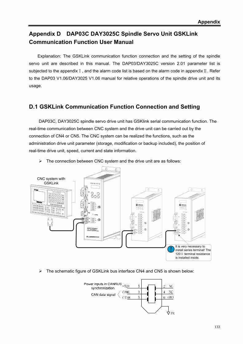
Appendix
133
Appendix D DAP03C DAY3025C Spindle Servo Unit GSKLink Communication Function User Manual
Explanation: The GSKLink communication function connection and the setting of the spindle
servo unit are described in this manual. The DAP03/DAY3025C version 2.01 parameter list is
subjected to the appendix , and the alarm code list is based on the alarm code in appendix . Refer Ⅰ Ⅱ
to the DAP03 V1.06/DAY3025 V1.06 manual for relative operations of the spindle drive unit and its
usage.
D.1 GSKLink Communication Function Connection and Setting
DAP03C, DAY3025C spindle servo drive unit has GSKlink serial communication function. The
real-time communication between CNC system and the drive unit can be carried out by the
connection of CN4 or CN5. The CNC system can be realized the functions, such as the
administration drive unit parameter (storage, modification or backup included), the position of
real-time drive unit, speed, current and state information.
The connection between CNC system and the drive unit are as follows:
It is very necessary to install series terminal! The 120Ω terminal resistance is installed inside.
CNC system with GSKLink
The schematic figure of GSKLink bus interface CN4 and CN5 is shown below:

DAP、DAY Series Spindle Servo Drive Unit User Manual
134
GSKLink communication connection figure between GSK988T CNC system and the drive
unit is shown below:
GSKLink communication connection figure between drive units:
GND
+12V
CANH
CANL
5
3
Casing
6
Drive unit A CN4 or CN5
1
2
4
GND
+12V
CANH
CANL
5
3
Casing
6
1
2
4
Drive unit B CN4 or CN5
Some relative parameters are required after the communication cable is connected properly:
Relative parameter
Name Unit Parameter
range Default Applicable
Servo slavery number setting of
GSKLink communication 1~5 5 P,S
PA19 Setting the interface number between the drive unit and instruction control unit communication. The communication can be performed as long as the drive unit and the CANBUS axis number of instruction control unit are same, but it is not same to the other CANBUS control axis numbers of the instruction control unit.
The setting GSKLink
communication baud rate 0~4 0 P,S
PA20
PA20=0: CANBUS communication function is OFF ;
PA20=1: Baud rate is set to 500kps;
PA20=2: Baud rate is set to 600kps;
PA20=3: Baud rate is set to 800kps;
PA20=4: Baud rate is set to 1Mbps.
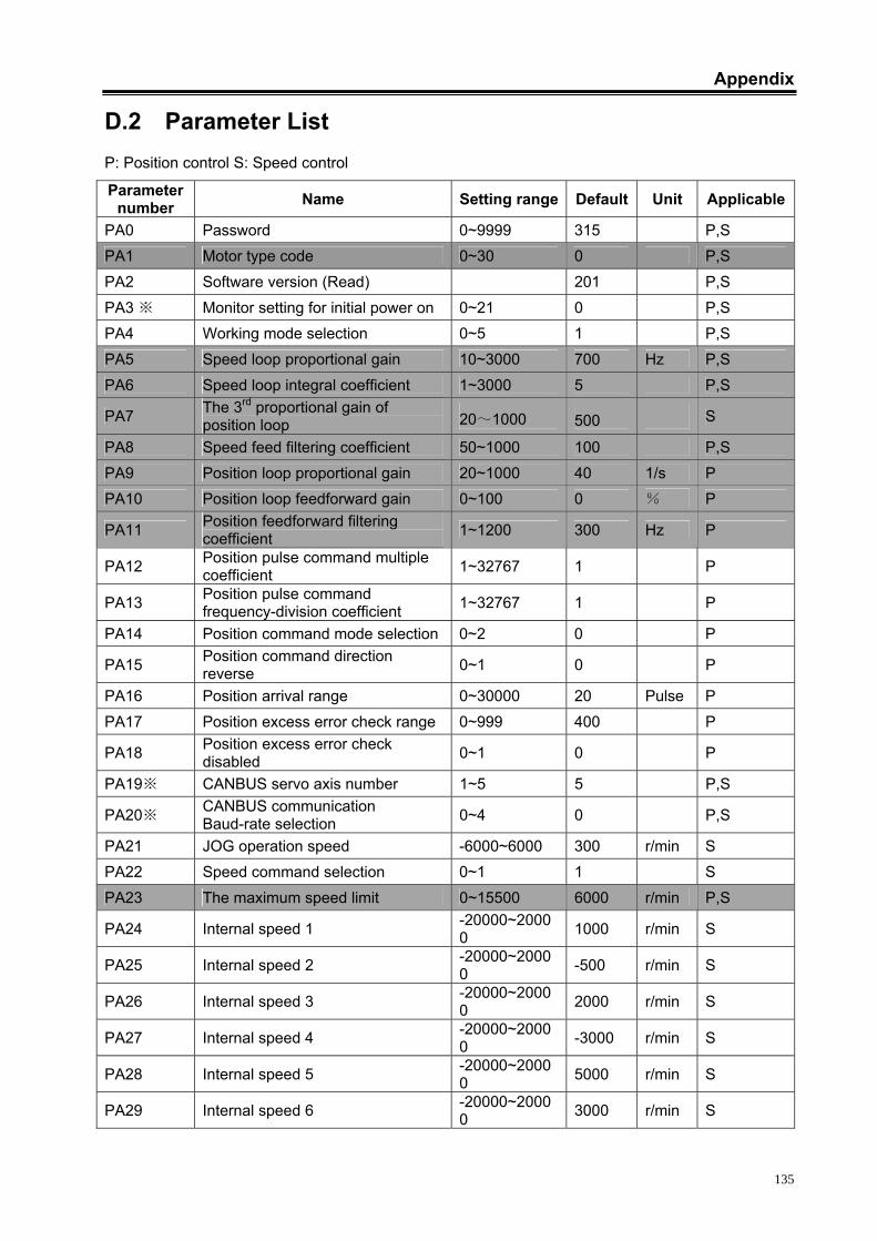
Appendix
135
D.2 Parameter List P: Position control S: Speed control
Parameter number Name Setting range Default Unit Applicable
PA0 Password 0~9999 315 P,S PA1 Motor type code 0~30 0 P,S
PA2 Software version (Read) 201 P,S
PA3 ※ Monitor setting for initial power on 0~21 0 P,S PA4 Working mode selection 0~5 1 P,S
PA5 Speed loop proportional gain 10~3000 700 Hz P,S
PA6 Speed loop integral coefficient 1~3000 5 P,S
PA7 The 3rd proportional gain of position loop 20~1000 500 S
PA8 Speed feed filtering coefficient 50~1000 100 P,S
PA9 Position loop proportional gain 20~1000 40 1/s P PA10 Position loop feedforward gain 0~100 0 % P
PA11 Position feedforward filtering coefficient 1~1200 300 Hz P
PA12 Position pulse command multiple coefficient 1~32767 1 P
PA13 Position pulse command frequency-division coefficient 1~32767 1 P
PA14 Position command mode selection 0~2 0 P
PA15 Position command direction reverse 0~1 0 P
PA16 Position arrival range 0~30000 20 Pulse P
PA17 Position excess error check range 0~999 400 P
PA18 Position excess error check disabled 0~1 0 P
PA19※ CANBUS servo axis number 1~5 5 P,S
PA20※ CANBUS communication Baud-rate selection 0~4 0 P,S
PA21 JOG operation speed -6000~6000 300 r/min S PA22 Speed command selection 0~1 1 S
PA23 The maximum speed limit 0~15500 6000 r/min P,S
PA24 Internal speed 1 -20000~20000 1000 r/min S
PA25 Internal speed 2 -20000~20000 -500 r/min S
PA26 Internal speed 3 -20000~20000 2000 r/min S
PA27 Internal speed 4 -20000~20000 -3000 r/min S
PA28 Internal speed 5 -20000~20000 5000 r/min S
PA29 Internal speed 6 -20000~20000 3000 r/min S
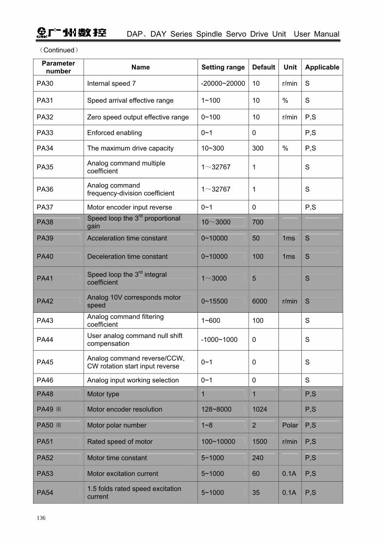
DAP、DAY Series Spindle Servo Drive Unit User Manual
136
(Continued)
Parameter number Name Setting range Default Unit Applicable
PA30 Internal speed 7 -20000~20000 10 r/min S
PA31 Speed arrival effective range 1~100 10 % S
PA32 Zero speed output effective range 0~100 10 r/min P,S
PA33 Enforced enabling 0~1 0 P,S
PA34 The maximum drive capacity 10~300 300 % P,S
PA35 Analog command multiple coefficient 1~32767 1 S
PA36 Analog command frequency-division coefficient 1~32767 1 S
PA37 Motor encoder input reverse 0~1 0 P,S
PA38 Speed loop the 3rd proportional gain 10~3000 700
PA39 Acceleration time constant 0~10000 50 1ms S
PA40 Deceleration time constant 0~10000 100 1ms S
PA41 Speed loop the 3rd integral coefficient 1~3000 5 S
PA42 Analog 10V corresponds motor speed 0~15500 6000 r/min S
PA43 Analog command filtering coefficient 1~600 100 S
PA44 User analog command null shift compensation -1000~1000 0 S
PA45 Analog command reverse/CCW, CW rotation start input reverse 0~1 0 S
PA46 Analog input working selection 0~1 0 S
PA48 Motor type 1 1 P,S
PA49 ※ Motor encoder resolution 128~8000 1024 P,S
PA50 ※ Motor polar number 1~8 2 Polar P,S
PA51 Rated speed of motor 100~10000 1500 r/min P,S
PA52 Motor time constant 5~1000 240 P,S
PA53 Motor excitation current 5~1000 60 0.1A P,S
PA54 1.5 folds rated speed excitation current 5~1000 35 0.1A P,S

Appendix
137
(Continued)
Parameter number Name Setting
range Default Unit Applicable
PA55 Orientation speed 10~1000 100 r/min S
PA56 Position window in orientation 0~100 2 Pulse S
PA57 Orientation selection 0~2 0 S
PA58 Positioning 1 0~30000 0 Pulse S
PA59 Positioning 2 0~30000 0 Pulse S
PA60 Positioning 3 0~30000 0 Pulse S
PA61 Positioning 4 0~30000 0 Pulse S
PA62 Positioning 5 0~30000 0 Pulse S
PA63 Positioning 6 0~30000 0 Pulse S
PA64 Positioning 7 0~30000 0 Pulse S
PA65 Positioning 8 0~30000 0 Pulse S
PA66 ※ Position feedback input signal selection 0~1 0 P,S
PA67 ※ The 2nd position encoder resolution 100~8000 1024 P,S
PA68 ※ The 2nd position feedback input signal reverse 0~1 0 P,S
PA69 Position feedback output selection 0~1 0 P,S
PA70 Position feedback output reverse 0~1 0 P,S
PA71 Position signal output quadruple selection 0~1 1 P,S
PA72 Alarm output reverse 0~1 0 P,S
PA73 Motor overheat alarm shield 0~1 0 P,S
PA74 Braking function selection 0~1 1 P,S
PA75 Analog command zero speed window 0~1000 0 r/min S
PA76 The mode selection from position shifting to speed 0~1 0 P,S
PA77 Speed/position shifting orientation 0~30000 0 Pulse P,S

DAP、DAY Series Spindle Servo Drive Unit User Manual
138
(Continued)
Parameter number Name Setting
range Default Unit Applicable
PA78 The top speed corresponds with the 10V analog command when the speed loop the 2nd gain is enabled.
0~15500 6000 r/min S
PA79 Speed loop the 2nd proportional gain 10~3000 700 Hz S
PA80 Speed loop the 2nd integral coefficient 1~3000 5 S
Development parameter: PA81~PA119
PA81 Current proportional gain 1~1000 100 P,S
PA82 Current integral time constant 1~1000 10 1ms P,S
PA83 IPM module available current top
percentage
20~90 70 1% P,S
PA84 Rated motor current 5~1000 190 0.1A P,S
PA85~PA86 Reserved
PA87 Speed integral separation point 100~20000 2000 r/min P,S
PA88 Braking time 10~32000 1000 0.1ms P,S
PA89 Overload time 6000~32000 6000 0.1ms P,S
PA90 Over-current time 200~32000 1000 0.1ms P,S
PA91 Rated input AC voltage 150~700 380 P,S
PA92 DC bus voltage coefficient 100~5000 2400 P,S
PA93 Speed feedback input selection 0~1 0 P,S
PA94 DC bus UV(under-voltage) 200~600 340 P,S
PA95 Current integral separation point 500~10000 4000
PA97~PA98 Reserved
PA99 Position filtering coefficient 1~10000 100
PA100 Charge mulfunction alarm shield 0~1 P,S
PA101 Open-phase alarm shield 0~1 0 P,S
PA102 UV(under-voltage) alarm shield 0~1 0 P,S
PA103 Encoder alarm shield 0~1 0 P,S

Appendix
139
(Continued)
Parameter number Name Setting
range Default Unit Applicable
PA104 Malfunction shielding due to the
temperature of cooling fin has
dropped
0~1 0 P,S
PA105~
PA106
Reserved
PA107 Too high temperature of cooling fin
mulfunction shield
0~1 0 P,S
PA108※ The maximum speed selection 1~5 2 P,S
PA109 Zero speed, the enabling valve value
OFF
1~32000 10 S
PA110~
PA111
Reserved
PA112 Electronic thermal relay over-heat
time
1~60 40 P,S
PA113 UVW wiring wrong alarm shield 0~1 0 P,S
PA114 Over-current alarm shield 0~1 0 P,S
PA115 Excitation current percentage in
position control mode
0~100 0 P,S
PA116 Current displays refreshing frequence 2~100 15
PA117 Excitation current constant 40~1000 100
PA118 Excitation current percentage in
speed control mode
0~100
PA119 Rated current percentage of motor 1~100
Productive parameter: PA120~PA123
PA120※ Current feedback resistance value 50~5000 330 0.1 欧 P,S
PA121※ Current sensor ratio 100~6000 1000 P,S
PA122 Reserved
PA123 Hardware analog command null -1000~1000 0 S
PA124 Positive slope adjustment -1000~1000 0 S
PA125 Negative slope adjustment -1000~1000 0 S
PA126 Reserved

DAP、DAY Series Spindle Servo Drive Unit User Manual
140
1. In this parameter list, the parameter with shadowed color, which the default setting is
related to the motor type code, different defaults are to be determined by the motors.
2. Note: The position and speed loop parameters may be used when PA04=4, we may
not describe all the matters in this manual.
D.3 The Significance and Troubleshooting of Alarm Codes
The drive unit has multi-protection function. The drive unit may stop the motor operation and the
operator panel may display the alarm code when the mulfunction is checked till the
power is turned on. The menu can be entered to check the current alarm code. The user
can check the relative content of this chapter in terms of the alarm code to find out the mulfunction
and settle it.
Alarm number
Significant Main reason Troubleshooting
1. Encoder feedback signal abnormal;
Check the connection of the motor or the 2nd position encoder and other signal cables.
2. In the mode of speed, the acceleration/deceleration time constant is excessively small so that the speed overshoot is too high;
The acceleration time PA39 and the deceleration time PA40 are increased.
3. PA23 (the maximum speed limit) set excessively small or PA49 (motor encoder resolution) set smaller than the actual one;
PA23 and PA49 parameter values are correctly set in terms of the motor nameplate.
Err-1
Spindle motor speed exceeds the setting value (Refer to the PA23 parameter for the top speed limit).
4. Control panel malfunction Change the drive unit.
1. The brake resistance is not connected or being damaged.
Check the brake resistance and its connection.
Err-2 Main circuit DC bus voltage is excessively high. 2. The brake resistance is not
matched (excessive resistance value). Note: The less the brake resistance value is, the more the current of the brake circuit is, and the brake tube in brake circuit is easily damaged.
A. Change the brake resistance matched with the resistance value and power; B. Reduce the start frequency in terms of the service condition; C. Acceleration/deceleration time can be increased and the speed mode adjustment PA39/PA40

Appendix
141
can be adjusted in terms of the service condition.
3. The power supply is instable; Check the power supply.
4. The internal brake circuit is being damaged.
Change the drive unit.
1. The capacitance input is inadequate causing the power is lower;
Check the power capacitance and the control cabinet electric part.
Err-3 Main circuit DC bus voltage excessively low
2. The drive unit control panel malfunction may occur when the power is turned on.
Change the drive unit.
1. The pulse command frequency is excessively high or the electron gear ratio setting too big;
Check the instruction control unit command frequency, and check the setting of electron gear ratio PA12/PA13.
2. Load inertia is excessive, or the torque is inadequate
A. Check the motor overload multiple set (refer to the PA34 parameter explanation);
B. Add the drive unit and motor power; C. Reduce the load.
3. The motor encoder malfunction occurs or the encoder resolution set is wrong;
Check the motor encoder and its connection, and check the setting of PA49.
4. The motor U, V and W phases are incorrect, the Err-13 or Err-27 alarm may be issued therefore.
Change two phases randomly
5. PA68 is set incorrect, and the feedback signal is abnormal when the 2nd position encoder is used.
Check the set of PA68.
6. The position loop or speed loop gain set is excessively small (refer to PA5, PA6 and PA9)
Adjust speed loop or position loop gain.
Err-4 The number of position error counter exceeds the setting value (Refer to position excess-error check range set by PA17) (PA18=0: check the position excess-error alarm; PA18=1: do not check the position excess-error alarm.)
7. Position excess error effective range set is too small.
Set PA17 correctly.
Err-5 The temperature of the motor is excessively high,
1. The temperature check device does not work inside measuring equipment in the
Set PA73=1, shield the motor overheat alarm

DAP、DAY Series Spindle Servo Drive Unit User Manual
142
motor;
2. The excess overload caused the motor is heated badly;
Add the drive unit and motor power or reduce the load.
3. In the case of overload, the start/stop frequency is excessively high.
Reduce the start/stop frequency, improve the motor radiating condition.
4. The temperature check device, or the cooling fan of the motor may damaged or the external motor malfunctions.
Change the spindle servo motor.
and the alarm is issued. The overheat alarm signal output from the motor is checked by the drive unit. (PA73=0: Detect the motor over-heat alarm; PA73=1: do not detect the position excess-error (the overheating motor alarm.)
5. The temperature check signal of motor is normal, but the drive unit control panel is broken-down
Change the drive unit.
1. The setting of position command electron gear ratio is excessively big;
Check the set of PA12 and PA13.
Err-8 Position error counter overflow
2. The command pulse input is abnormal.
Check the instruction control unit command pulse frequency.
1. The wiring of the motor encoder signal is poor connected or disconnected;
Check the connector and the signal wire welding
2. The motor encoder signal feedback cable is too long caused the signal voltage is lower.
Shorten the cable length (within 30m).
3. The motor encoder is damaged;
Change the motor or the encoder.
Err-9 Motor code signal feedback abnormal
4. Drive unit control panel is defective.
Change the drive unit.
1. After the power is turned on, the malfunction occurs when the drive unit isn’t enabled and it can’t be eliminated; A. The drive unit control panel is defective; B. Short circuit is performed between the brake resistance wiring terminal and grounding.
Change the drive unit if it is reason A; Check and connect the brake resistance if it is the reason B
Err-11 IPM module malfunction inside
the drive unit
2. The malfunction occurs when It is caused by the poor

Appendix
143
the drive unit is disabled and it can be eliminated after the power is turned on again.
grounding or external interruption. Check the grounding, and search the interruption source, and keep away from the source of interruption or shield.
3. The malfunction occurs when the drive unit is enabled and can not be eliminated after the power is turned on. A. The motor is short among the wiring U, V and W; B. Drive unit IPM module is damaged.
Changing the motor wire or motor if it is caused by the reason A Change the drive unit if it is caused by the reason B.
Err-11 IPM module
malfunction inside
the drive unit
4. It may occur when the motor
is started or stopped and it may
be eliminated after the power is
turned on again.
A: Motor default parameters set
by the drive unit is incorrectly;
B. The load inertia is excessive,
and the command acceleration
rate is excessive while the start
or stop is performed.
The motor default parameter
operation is restored again if it is
the reason A. (Refer to the
Section 4.4 for details);
Increase the
acceleration/deceleration time of
the command and decrease the
acceleration rate of the
command, if it is the reason B. or
reduce the load inertia;
1. Motor is overcurrent for long
time;
Reduce the load.
2. Parameter setting is incorrect,
the motor vibration or abnormal
noise may occur.
Readjust the capability
parameter related to the motor.
(Refer to PA5, PA6, PA8, PA9
and PA34)
3. The PA49 set value is bigger
than the actual encoder
resolution;
Motor encoder resolution is set
correctly.
Err-13 Overload alarm in
motor operation
4. The power ON operation is
similar with the Err-27 alarm
caused by incorrect wiring U, V
and W.
Two-phase is changed randomly.
Err-16 Motor overload
alarm occurs
during operating
Motor overload operation is
performed longer than Err-13.
A. Reduce the load;
B. Change the drive device with
higher power
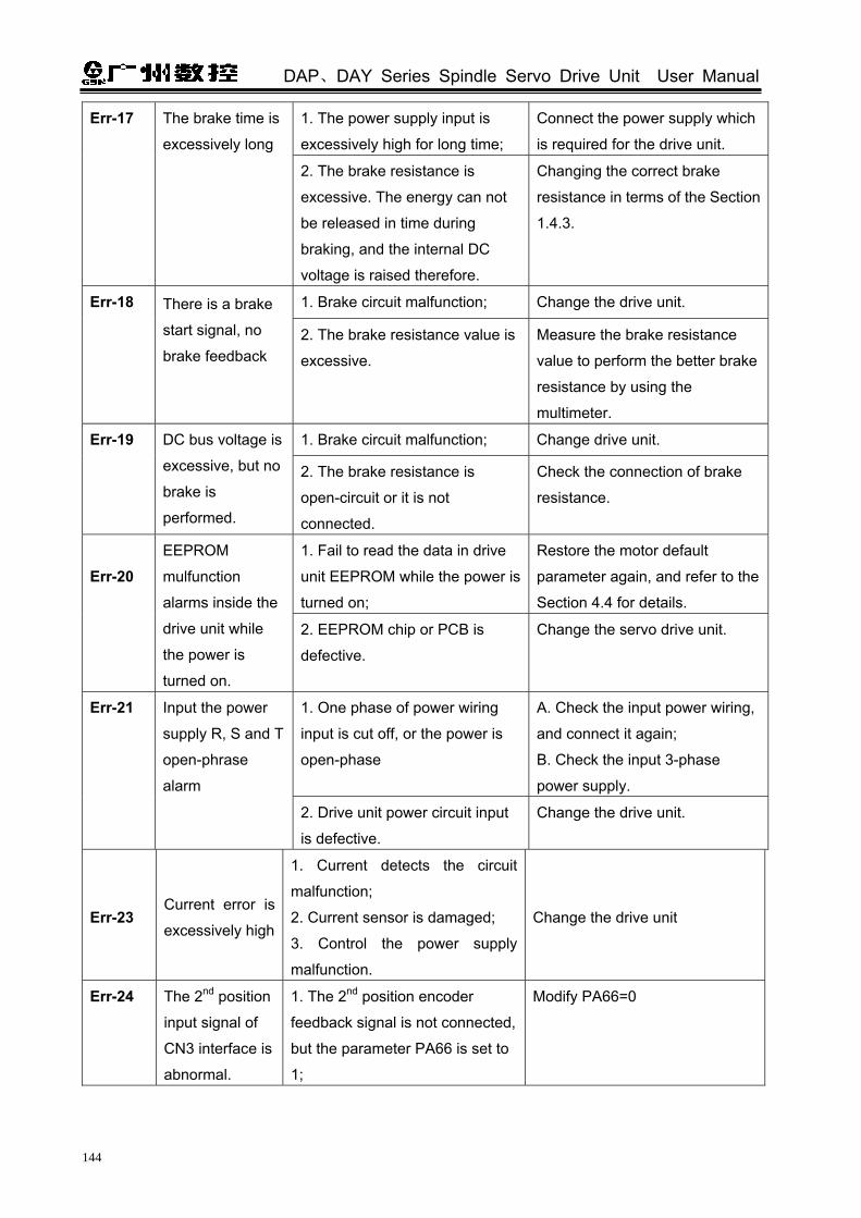
DAP、DAY Series Spindle Servo Drive Unit User Manual
144
1. The power supply input is
excessively high for long time;
Connect the power supply which
is required for the drive unit.
Err-17 The brake time is
excessively long
2. The brake resistance is
excessive. The energy can not
be released in time during
braking, and the internal DC
voltage is raised therefore.
Changing the correct brake
resistance in terms of the Section
1.4.3.
1. Brake circuit malfunction; Change the drive unit. Err-18 There is a brake
start signal, no
brake feedback 2. The brake resistance value is
excessive.
Measure the brake resistance
value to perform the better brake
resistance by using the
multimeter.
1. Brake circuit malfunction; Change drive unit. Err-19 DC bus voltage is
excessive, but no
brake is
performed.
2. The brake resistance is
open-circuit or it is not
connected.
Check the connection of brake
resistance.
1. Fail to read the data in drive
unit EEPROM while the power is
turned on;
Restore the motor default
parameter again, and refer to the
Section 4.4 for details.
Err-20
EEPROM
mulfunction
alarms inside the
drive unit while
the power is
turned on.
2. EEPROM chip or PCB is
defective.
Change the servo drive unit.
1. One phase of power wiring
input is cut off, or the power is
open-phase
A. Check the input power wiring,
and connect it again;
B. Check the input 3-phase
power supply.
Err-21 Input the power
supply R, S and T
open-phrase
alarm
2. Drive unit power circuit input
is defective.
Change the drive unit.
Err-23 Current error is
excessively high
1. Current detects the circuit
malfunction;
2. Current sensor is damaged;
3. Control the power supply
malfunction.
Change the drive unit
Err-24 The 2nd position
input signal of
CN3 interface is
abnormal.
1. The 2nd position encoder
feedback signal is not connected,
but the parameter PA66 is set to
1;
Modify PA66=0

Appendix
145
2. The spindle encoder feedback
signal is abnormal. (It is same
reason with that of Err-9 alarm)
A. The 2nd position encoder
signal wiring, the welding as well
the connection of the socket are
checked.
B. The encoder cable is
excessively long which may
cause the signal voltage is low, it
is necessary to short the cable
(within 30m).
1. Pulse signal Z can not be
detected;
Check the feedback input signal
wiring.
2. The corresponding parameter
set is improper or the gain setting
is excessive due to the load
inertia is bigger.
Check the relative parameter
value PA49, PA66 and PA67.
The debugging method, such as
the corresponding gain
parameter PA5, PA6, PA8 and
PA9 refer to the Section 6.1.
Err-25 Fail to orientate
the drive unit
3. The spindle encoder phase
sequence is inconsistent with the
motor encoder signal A/B when
the 2nd position input signal
orientation is used.
Modifying the parameter PA68,
the phase sequence is turned
into coincidental, refer to the
PA68 explanation.
Err-27 Wrong wiring
among U, V and
W.
The drive unit main circuit output
U, V and W for the phase
sequence of its motor which is
incorrect.
Two phases of them can be
changed randomly.
Err-28 The software
upgrade
parameter is
wrong.
Parameter readjustment and
storage are not performed after
the software is copied or
upgraded.
A default parameter is called
again, and the parameter is
stored after the power is turned
on again.
Err-29 Parameter
detection is
incorrect when
the power is
turned on.
It is caused the conflict between
the new and old versions when
the version is upgraded.
Parameter write operation is
performed, and the power is
turned on again.
Err-33 The main circuit
voltage is
abnormal when
the power is
1. The input voltage is
excessively low or voltage wave
is too high at the instant of power
ON.
Check the input power

DAP、DAY Series Spindle Servo Drive Unit User Manual
146
turned on. 2. Rectifier is damaged or soft
start circuit is defective.
Change the drive unit.
Err-34 Pulse electron
gear ratio is
excessively big.
The pulse command frequency is excessively high or the electron gear ratio set is excessively big;
Check the instruction control unit
command frequency, and the
setting of electron gear ratio
PA12/PA13.
1. The temperature of cooling fan
is less than -30 .
The ambient temperature is
excessively low, which exceeds
the capacity of the drive unit.
Err-37 The
temperature of
cooling fan is
excessively low. 2. The thermistor is abnormal. Change the drive unit
1. The temperature of cooling fin
is more than 90 .
Reduce the temperature of
cooling fin
Err-38 The
temperature of
cooling fin is
excessively
high.
2. The thermistor is abnormal. Change the drive unit
Software Supplement Explanation of DAY3000 (V1.09) and DAP03 (V1.08)
Number: 2S09090701A
This supplement explanation is suitable for the software version both DAY3000 V1.09
and DAP03 V1.08, which is regarded as the supplement technical document DAP03, DAY3025, DAY3100 AC Spindle Servo Drive Unit User Manual (The 2nd version in Apr. 2009) with the DAY3000 and DAP03.
The detailed descriptions are shown below: 1. Added 3 motors’ parameters
Type: ZJY182-1.5B, the corresponding type code parameter is PA1=17;
Type: ZJY182-2.2B, the corresponding type code parameter is PA1=18;
Type: ZJY182-3.7B, the corresponding type code parameter is PA1=19
2. The spindle drive unit and adapted spindle servo motor list:

Appendix
147
Adapted spindle motor Main parameter of spindle motor
Drive unit type Motor type PA1
Rated power(kW)
Rated
torque
(N•m)
Rated
speed
(r/min)
The max.
speed
(r/min)
Rated
current Encoder
Remark
DAY3025 ZJY182-1.5BM
(ZJY182-1.5BH) 17 1.5 9.5 1500
7000 (10000)
7.3 A 1024 cables
incrementalAdded
DAY3025 ZJY182-2.2BM
(ZJY182-2.2BH) 18 2.2 14 1500
7000 (10000)
7.5 A 1024 cables
incrementalAdded
DAY3050 ZJY182-3.7BM
(ZJY182-3.7BH) 19 3.7 24 1500
7000 (10000)
15.5A 1024 cables
incrementalAdded
DAY3025 ZJY208-2.2BM 21 2.2 14.5 1500 7000 9.3A 1024 cables
incremental
DAY3050 ZJY208-3.7BM
(ZJY208-3.7BH) 22 3.7 24 1500
7000 (10000)
8.9A 1024 cables
incremental
DAP03-055 ZJY208-5.5BM
(ZJY208-5.5BH) 23 5.5 35 1500
7000 (10000)
13.7A 1024 cables
incremental
ZJY208-7.5BM
(ZJY208-7.5BH) 24 7.5 48 1500
7000 (10000)
18.4A 1024 cables
incremental
DAP03-075 ZJY265-7.5BM 25 7.5 49 1500 7000 18A
1024 cables
incremental
DAP03-110 ZJY265-11BM 26 11 72 1500 7000 26A 1024 cables
incremental
DAY3100 ZJY265-15BM 27 15 98 1500 7000 35A 1024 cables
incremental
Note: PA1 is the No. 1 parameter of servo drive unit, and the parameter values are the adapted servo
motor type codes.

DAP、DAY Series Spindle Servo Drive Unit User Manual
148
Software Supplement Explanation of DAY3000 (V1.11) and DAP03 (V1.10)
Number: 2S100415A
This supplement explanation is suitable fro the software version both DAY3000 V1.11 and DAP03 V1.10, which is regarded as technical document with AC Spindle Servo Drive Unit Use Manual (Speed printing version the 1st Feb. 2010) offers to the users. The software version DAP03 V1.10 and DAY3000 V1.11 are the updated version for the DAP03
V1.08 and DAY3000 V1.09 separately. The detailed descriptions are shown below:
1. Added the spindle hold control function Function description: The drilling or tapping is performed when the spindle orientation is
completed or arrived to a position, the spindle should be clenched or clamped. In this case, The CNC
offers a hold signal to the servo spindle drive unit, and the spindle is in the “Free” state after the hold
is finished, and the motor is on the non-excite state. In this case, the enable signal of CNC must on
the valid state, and can not be cut off. The CNC retracts the hold signal after the machining is
performed. The servo drive unit restores the motor’s exiting state after receiving the command of hold
release, which is on the front of the hold locking spindle. The hold state delay time can be set in the
servo drive parameter (PA111) after the external retraction hold command is performed. If the servo
motor hold control relay is controlled (for example, the PLC control of CNC) by the instruction control
unit. It is recommended that the hold delay time after the retraction of the hold command is set by the
instruction control unit. I/O interface signal: The hold signal on the spindle servo side and the zero speed clamping
signal are used duplicately, it is the latter one in the speed mode, and the former one in the position
mode. Relative parameters: 1) PA4=1, it is [OFF] when the orientation start signal is disabled, and the ZSL signal is zero
speed clamping signal; it is [ON] when the ZSL signal input is enabled after the orientation is
performed, the ZSL is the spindle hold signal. In this case, the motor is on the Free State.
2) PA4=5, it is [OFF] when the speed/position shift signal (V/P) is disabled, the ZSL signal is zero
speed clamping signal; it is [ON] when the ZSL signal input is enabled after the speed/position shift is
performed, ZSL is the spindle hold signal. In this case, the motor is on the Free State.
4) PA111: hold delay time, the default value is 300, Unit: 1.6ms, the resolution range is [0~
32000]
If the servo motor hold control relay is controlled (for example, the PLC control of the
CNC) by the instruction control unit, It is recommended that the hold delay time after the
retraction of the hold command is set by the instruction control unit.

Appendix
149
Explanation: It is [ON] when the ZSL signal input is enabled, the optical coupling of signal input
circuit is conducted; it is [OFF] when the ZSL signal input is disabled, the optical coupling of signal
input circuit is stopped.
The external switch
example
The external optical
coupler example
Fig.D- 5 The example of ZSL signal interface


