FLAMES LIBATIONS 8.00 FLAME-TINIS - Late Night Diner in Downtown

ncassi'fiedv CLASSIFICATION OF THIS PAGE
REPORT I Form Approved
8 ; -P ORT SECURITY CLASSIFICATION _' J '4Unclassified LA J AD-A227 170,',a SECURITY CLASSIFICATION AUTHO " I LITY OF REPORT
Approved for public release;?r DCLASSIFICATION/DOWNGRADI CHE 9 2 6 1990 distribution is unlimited
4 PERFORMING ORGANIZATION RE P MBER(S) S MONITORING ORGANIZATION REPORT NUMBER(S)
D AFOSR-TR. (I (1 1,
6a NAME OF PERFORMING ORGANIZATION b OFFICE SYMBOL 7a. NAME OF MONITORING ORGANIZATIONCase Western Reserve (If applicable)University AFOSR/NA
6( ADDRESS (City, State, and ZIPCode) 7b. ADDRESS (City, State. and ZIP Code)
University Circle Building 410, Bolling AFB DCCleveland, Ohio 44106 20332-6448
,-i '.AME OF FUNDING/SPONSORING 8b OFFICE SYMBOL 9 PROCUREMENT INSTRUMENT IDENTIFICATION NUMBERORGANIZATION (if applicabl e#AFOSR/NA J AFOSR 85-0340
B. A DDRESS (City, State, and ZIP Code) 10 SOURCE OF FUNDING NUMBERS
PROGRAM PROJECT TASK WORK UNITBuilding 410, Bolling AFB DC ELEMENT NO NO. NO ACCESSION NO20332-6448 61102F 2308 Al
1 TITLE (Include Security Classification)
(U)Solid Fuel Combustion
2 PERSONAL AUTHOR(S)
James S. T'ien
13a TYPE OF REPORT 13b TIME COVERED 14. DATE OF REPORT (Year, Month, Day) 115. PAGE COUNTFinal Report FROM 8/1/85 TO1 0 / 3 1 / 8 c August, 1990 78
16 SUPPLEMENTARY NOTATION
17. COSATI CODES 18. SUBJECT TERMS (Continu.T on reverse if necessary and identify by block number)FIELD GROUP SUB-GROUP diffusion flame, solid fuel, flame radiation
thermophoresis
19 ABSTRACT (Continue on reverse if necessary and identify by block number),, Theoretical analyses were performed on several different types of diffusion flames
to study the flame radiation effect. In the first problem, a soot formation and oxida-
tion scheme was incorporated into a turbulent diffusion flame model adjacent to a solid
fuel. The computed results for the natural convective fire showed good agreement with
experimentally measured solid fuel burning rate. Soot radiation increased its im-portance with flame height. With flames greater than I meter, the radiative heat fluxexceeded that by convection. In the second problem, matched asymptotic expansions wereemplcyed to study the spherical diffusion flame around a droplet or solid particle withflame radiation. It was found that the importance of radiation increased with dropletradius. The theory predicted that there was a maximum droplet or particle size abovewhich a spherical flame could not be supported due to radiative loss. In the thirdproblem, the thermophoretic motion of sm 11 particles (e.g., soot) were studied in astagnation-point laminar flow next to aeated plate with and without combustion.
20. DISTRIBUTIGJ, %VAILABILITY OF ABSTRACT 21. ABSTRACT SECURITY CLASSIFICATION
29UNCLASSIFIEDUNLIMITED CM SAME AS RPT. /DTIC USERS Unclassified22& NAME OF RESPONSIBLE INDIVIDUAL 22b. TELEPHONE (Include Area Code) 22c. OFFICE SYMBOL
Dr Mitat Birkan (202)767-4937 AFOSR/NADO Form 1473, JUN 86 Previous editions are obsolete. SECURITY CLASSIFICATION OF THIS PAGE
Unclassified

19. Abstract (continued)
It was found that both the thermophoretic motion and the Brownian particle diffusioncan have a profound effect on the particle concentration distributions.

46,~
SOLID FUEL COMBUSTION
James S. T'ien
Case Western Reserve UniversityCleveland, Ohio 44106
August 1990
Final Report for AFOSR Grant 85-0340
Covering Period August 1, 1985 - October 3 1989

IIII
I
H SOLID FUEL COMBUSTION
James S. T'ienCase Western Reserve University
Cleveland, Ohio 44106
1 August 1990
Final Report for AFOSR Grant 85-0340
Covering Period August 1, 1985 - October 3, 1989
I Prepared for
AIR FORCE OFFICE OF SCIENTIFIC RESEARCHBolling AFB, D. C. 20332-6448
Accir( For
I UTI 4~&NI,
Jushf'c31,, r,
By
Dist
I

II* Table of Contents
Page
i Title Page 1
DD Form 1473 2
i Table of Contents 3
* I. Summary 4
II. Research Objective 5
3 III. Research Accomplishments 5
IV. Publications 11
i V. Oral Presentations 12
VI. Participating Professionals 13
Appendix
A. The Effect of Soot Radiation on theCombustion of Solid Fuels Al
B. Structure and Extinction of Diffusion Flameswith Flame Radiation B1
C. Diffusion Layer Structure in aThermophoretically Affected Flow Over A HotSurface C1
[3I

IU
I. SUMMARY
Theoretical analyses were performed on several
different types of diffusion flames to study the flame
radiation effect. In the first problem, a soot formation
I and oxidation scheme was incorporated into a turbulent
diffusion flame model adjacent to a solid fuel. The
computed results for the natural convective fire showed good
agreement with experimentally measured solid fuel burning
rate. Soot radiation increased its importance with flame
I height. When flame length is greater than one meter, the
local radiative heat flux exceeded that by convection. In
the second problem, matched asymptotic expansions were
employed to study the spherical diffusion flame around a
droplet or solid particle with flame radiation. It was
3 found that the importance of radiation increased with
droplet radius. The theory predicted that there was a
ymaximum droplet or particle size above which a spherical
3 flame could not be supported due to radiative loss. In the
third problem, the thermophoretic motion of small particles
(e.g., soot) were studied in a stagnation-point laminar
diffusion flame. It was found that both the thermophoretic
I motion and the Brownian particle diffusion can have a
3 profound effect on the particle concentration distributions
which in turn will affect the radiative heat transfer.
II4I

iI
II. RESEARCH OBJECTIVE
The main objective of this research is to study
the effect of flame radiation on diffusion flames, in 3particular those related to solid and condensed-phase fuels. IIII. RESEARCH ACCOMPLISHMENTS
The major accomplishments in the research program
will be briefly described in this section. Detailed results 3are contained in the Appendices and the list of publications. I(A) The Effect of Soot Radiation on the Combustion of Solid
Fuels in Turbulent Boundary Layers 3The first part of the effort dealt with the
adoption of low-Reynolds-number K-c model for solid fuel Iburning. In this work, the chemical kinetics are assumed to 3be infinitely fast and the mixture fraction is assumed to
obey a beta probability density distribution. This work 3shows that the low-Reynolds-number K-c approach is more
physically revealing than the wall function method in ianalyzing the surface boundary layer problem. By adopting 3the low-Reynolds-number model where the same equations apply
all the way to the wall, we have discovered a number of i
limitations and problems which are hidden in the wall
function approach. To name a few, the equation for mixture ifraction is no longer homogeneous, as assumed in all the
5i

I
previous studies. The evaluation of mean mass fractions for
fuel and oxidizer requires certain assumption of small
disturbance. The boundary condition for g (square of
mixture fraction fluctuation) requires the specification of
_ K (turbulent and kinetic energy) at the wall. With a
pyrolyzing solid surface the value of K can be an issue.w
Most details can be found in Publication List No. 1.
In the second part of the effort, finite-rate
chemistry was added through an eddy-dissipation model. In
I addition to convection and diffusive contribution, a soot
* formation and oxidation scheme is also included in the soot
transport equation to compute soot concentration. Radiative
heat transfer is calculated by using a two-flux method. The
model was applied to the vertical burning of a PMMA slab
I where there were measured radiation data.
In the step-by-step comparison with experiment, it
is found that low-Reynolds-number K-c turbulence model can
* produce good heat flux at surface without any modification
in pure natural convection along a heated plate. The
* modification of the low Reynolds number term to accommodate
surface mass addition is made in this study. The complete
model, when applied to the turbulent wall fire, produces
3 good burning rate, radiant heat flux and average soot volume
fraction. The soot radiation is demonstrated to be
3 important in determining the burning rate of solid fuel.
!6

I
More details can be found in Publication List No. 2, which
is attached in Appendix A. I(B) Structure and Extinction of Diffusion Flame with Flame
Radiation (Publication List No. 3, Appendix B)
Using droplet combustion as a model problem, and
capitalizing on the temperature-sensitive nature of 3radiative heat transfer, the structure and extinction of
diffusion flames with flame radiation is studied via Umulti-scale activation energy asymptotics. The flame
structure analyzed consists of an O(c) reaction zone
embedded within an 0(6) radiation zone which in turn is
situated on the 0(i) diffusive-convective flow field, where
C 6 < 1. The analysis yields the structure equation for Ithe reaction zone, which can be cast in the same form as
that of Linan's adiabatic diffusion flame problem such that
his extinction results can be readily used. Present results
show that radiative heat loss promotes flame extinction in
general, as expected. Furthermore, it can also lead to the Iphenomenon of dual extinction turning points in which flame
extinction due to reactant leakage and thereby kinetic
limitation occurs not only for sufficiently small droplets, 3as is well established, but also for sufficiently large
droplets as a result of excessive heat loss from the Icorrespondingly large flame. Consequently, there exist 3
7I
I
Ii
diffusive-reactive-radiative systems for which steady
combustion is not possible for all droplet sizes. An
estimation of the dimensional radiative extinction droplet
size is also given for the sample system studied. More
details can be found in Publication List No. 3 which is also
attached as Appendix B. This work has been collaborated
with Dr. B. H. Chao and Professor C. K. Law of Princeton
i University.
(C) Concentration Distribution of Particles in aThermophoretically Affected Flow Field
The magnitude of soot radiative emission depends
not only on the soot concentration level but also depends on
where the soot locations are in the flame (because of
different temperature). Therefore the soot particle profile
is important for radiative calculation. Since it is known
that soot particles are subject to thermophoretic motion in
flames, we have undertaken this effort to investigate the
effect of thermophoresis and particle Brownian diffusion on
particle profiles.
In the first effort, a theoretical analysis is
performed to study the distribution of small-size particles
in the stagnation-point region of a hot wall (no
3 combustion). Because of the thermophoretic motion, a
particle stagnation point is created in the interior of the
I8
I

Iflow which can produce singularity when particle diffusion 3is neglected. By including Brownian diffusion and using
matched asymptotic expansions, the structure of the inner
diffusion layer near the particle stagnation point is
resolved. The results presented in Appendix C illustrate
how the diffusion layer is evolved and its structural
variation with a number of parameters.
In the second part of the effort, a 3two-dimensional counterflow diffusion flame stabilized in
the forward stagnation region of porous cylinder is Ianalyzed. Fuel is ejected from the cylinder with a 3specified blowing velocity and diffuses into an oxidizer
flow of specified stagnation velocity gradient. In this 3configuration, particles (e.g., soot) of an assumed average
dimension form at a global rate depending on the local fuel Iconcentration and temperature. Thermophoresis gives rise to
many different flow patterns for the particles depending on
the flame structure and the magnitude of thermophoretic
coefficient. In some cases, multiple stagnation points for
particle flow exist. IBrownian diffusion needs to be included in this
theoretical treatment in order to avoid singular behavior
(infinite particle concentration) at the stagnation point 3under certain conditions. Because the Schmidt number
associated with the Brownian diffusion is very large a I
9 II

II
special numerical scheme was developed to solve the mass
conservation equation for the particles. The numerical
scheme was implemented in two stages and allowed to
integrate the equation even in situations for multiple
turning points (points where particle velocity changes
direction). This was achieved by making use of an adaptive
mesh refinement scheme.
* For cases along the center streamline where the
particles are convected toward the stagnation point, a
boundary layer behavior is observed. When the product of
Prandtl number a the thermophoretic coefficient is greater
than a critical value (nearly unity - slightly influenced by
* chemical kinetics), a local peak of particle concentration
is predicted. For cases where particle velocity is from the
fuel-rich side toward the flame, the particles, generated in
the fuel-rich side (such as soot), can leak through the
I flame and appear on the fuel-lean side.This can occur only
when the stoichiometric fuel-oxidizer mass ratio is less
than unity. The detailed profile of particle concentration
in counterflow diffusion flames, therefore, depends on many
parameters. More details can be found in Publication List
I No. 5.
II
I

ii
IV. PUBLICATIONS
1. D. Y. Shan and J. S. T'ien: Application ofLow-Reynolds-Number K-c Model to Solid Fuel TurbulentBoundary Layer Combustion, AIAA Paper 87-1778 (1987).
2. S. T. Lee and J. S. T'ien: The Effect of SootRadiation on the Combustion of Solid Fuels, Journal ofthe Chinese Society of Mechanical Engineers, Vol. 10,No. 4, pp. 243-253 (1989).
3. B. H. Chao, C. K. Law, and J. S. T'ien: Structure andExtinction of Diffusion Flames with Flame Radiation,Twenty-Third Symposium (International) on Combustion,Orleans, France, July, 1990 (In press).
4. N. Ait Messaoudene and J. S. T'ien: Diffusion LayerStructure in a Thermophoretically Affected Flow Over aHot Surface,Submitted to International Journal of Heat
and Mass Transfer.
5. N. Ait Messaoudene and J. S. T'ien: The Effect of iThermophoresis on Particle Distribution in Opposed-FlowLaminar Diffusion Flames, Article in preparation forCombustion Science and Technology.
I
I
iIIi

II
V. ORAL PRESENTATIONSI1. Application of Low-Reynolds-Number K-c Model to Solid
Fuel Turbulent Boundary Layer Combustion,AIAA/SAE/ASME/ASEE 23rd Joint Propulsion Conference,June 29-July 2, 1987, San Diego, California.
i 2. The Effect of Soot Radiation on the Combustion of SolidFue Ls, AIAA/ASME/SAE/ASEE 24th Joint PropulsionConference, July 11-13, 1988, Boston, Massachusetts.
3. Structure and Extinction of Diffusion Flames with FlameRadiation, Twenty-Third Symposium (Int.) on Combustion,Orleans, France, July 22-27, 1990.
4. Solid Fuel Combustion, AFOSR Contractor's Meetings,1986, 1987, 1988, 1989.
IIIIIIIII
I

lI
VI. PARTICIPATING PROFESSIONALS:
Professor J. S. T'ien: Case Western Reserve University,Principal Investigator
Mr. D. Y. Shan: Ph.D. candidate, Case Western ReserveUniversity I
Mr. N. Ait Messaoudene: Ph.D. candidate, Case WesternReserve University
Professor S. T. Lee: Visiting Associate Professor, CaseWestern Reserve University (on leave from NationalTaiwan University)
Collaborators:
Dr. B. H. Chao and Professor C. K. Law, Princeton University
Degrees Awarded: i1. D. Y. Shan, Ph.D., 1987 i
Thesis title: Application of Low-Reynolds-Number X-cModel to Solid Fuel Turbulent Boundary
Layer Combustion.,
2. N. Ait Messaoudene, Ph.D., 1989
Thesis title: Concentration Distribution of Particles iin a Thermophoretically Affected FlowField With and Without Combustion.
IIII
I

IIIIII* Appendix A
IIIIIIIIIIII Al

I4 ff - -I A,+ ,4 243-253 F - +, -- 4-
Journal of the Chinese Society of Mechanical Engineers, Vol. 10. No. 4. pp. 243-253 (1989) i
The Effect of Soot Radiation on theCombustion of Solid Fuels i
Shih-Tuen Lee 3Department of Mechanical Engineering
National Taiwan Universitv
Taipei. Taiwan. 10764, R.O.C.
James S. T'ienDepartment of .Mechanical and Aerospace Engineering
Case Western Reserve Univer ttv
Cleveland, Ohio 44106
Keywords: solid fuel, turbulent combustion, soot, radiation. i
IABSTRACT
A comprehensive model for turbulent boundary layer combustion adjacent to solid fuels is estab- i
lished and employed to study the influence of thermal radiation on the burning rate of solid fuels. A low-
Reynolds-number two-equation K - e model is used for flow transport. The treatment of turbulence and
chemistry interaction follows the eddy-dissipation model. Radiative heat transfer is calculated by using a
two-flux method. In addition to convection and diffusive contribultion, the soot lrmation and oxidation
are also included in the soot transport equation to compute the soot concentration.
Comparisons between model calculations and experimental data are carefully carried out for a verti-
cally-burning PMMA fire. Consistent with the experiment results, the model calculation shows that radia-
tion to solid fuel is shown to be the most important factor in determining the solid pyrolysis rate.
I
II
ik fP Jd ,N' h
T-W Tkt V LL
M 2 3

IJ. CSME Vol. 10, No. 4 (19891
INTRODUCTION Truet
jurouientIn the nast decaide. a larkze amount or attention F~cn
::as ,,ien t,) ire stud\ Detailed experim ents 122. 26.[ " i,iQ:m,nistraied that although conwecu~on t,, the dominant = / "CltC
heat transfer mode n small scale itradaon heat iv/transter i,, the doninant mode in larve fires. For theburning ot hydroc:arbons ,or pol.,mers. it has long been . / q:metc
rcce)nied that soot particles are the important:jdijtion ources in the flame. Recentb,. it was pointedkj:t :12. 24. 31 that fuel pors or tletr de'corpnont K /,pr,)duLct also pla.' im portint roles in the tlaine ridia oi-',,!"- "/ S tf~
I tl~m. Therermle. i order to niodel tile burning hehaiaor f
11 Aaln, n s ,teins properiN, a theoreticalmodel houid he able to determine tie amount ot soot. 9: ;ei apor and combustion product, their distributionin he flame, tlamne ,hape and sie. "' n/,s
Theie are manv theoretical etfurts to model the ' rcmncr/ tDue t *rcs~t~c n
..,id fuel hurnmgn rate % hen radiation is ,icnificant. Al-thoui these radiation models ,ary in their comnplexities.Ihe\ are all hased on ,ery drastic assumptions. Forexamiple, in studying turbulent wall tires, two radiationmodels are assumed by Tamanini [321. In the first Ymodel. radiation power is assumed to be a constantiracution or the energy release rate- In the second model. Fig. Schematicottheprblemstudidthe radiation is postulated to emit from a thin, constant- consumption are neglected. Wc) the therniophoretictemperature layer of particles at the flame front and the motion ot soot is negtected. (t) the specilic heat Pvalue of enissivity of the flame sheet is chosen empiri- is constant, (g) Lewis numbers except for soot and soot,:ally. In the work of Methochianakis [231, the tame precursor are equal to one. (h) the ideal gas law appliesemiissivity is assumed to be related to the unburned fuel to the gas mixture.in an exponential manner. In Ref. II, radiative heat Following the mass-averaging procedure and orderflux is simply taken as constant mean value, of magnitude analysis, the following two-dimensional
The purpose of this article is to present a more boundary-layer equations are obtained.comprehensive model, compare its calculation withavailable data and evaluate the importance of sootradiation. This model includes several physical sub- N(r") + .(0 , (models which describe the turbulence phenomena, ax 6Yturbulence-chemistry interaction, radiation heat transfer 3 a -Aand the soot formation and oxidation. + +g(5-P) (2)
a___ ____ a (A- Y, = a Y1MATHEMATICAL MODEL a(+uY,) + a+ -Y, + W,')ax S Se t a"i
1. Mean Transport Equation a(pal,) a(PiF-/r) a /it )ahrThe physical situation studied is schematically ax 3Y 8V I Pr Ft "v
shown in Fig. 1. A turbulent buoyant flame is sustained a M r a( I / 2+ k)by the heat feedback to the solid fuel due to convective ay, N ,t N ayand radiative heat fluxes from the high temperaturegases in the flame. Some assumptions are made for easy + gxj + SR, (4)treatment of the problem: (a) the average flow is two-dimensional and steady, (b) the binary diffusion coef- RTficients for all pairs of species except soot and soot P W
precursor are equal, (c) mass diffusion due to pressuregradients, temperature gradient are neglected, (d) the where K is the turbulent kinetic energy and SR is thesoot and soot precursor are treated as minor species, heat addition due to radiation heat transfer. All thetheir heat of formation, combustion heat and oxygen other symbols are described in the Nomenclature.
* A3

IS.T. Lee and J.S. T'ien: The Effect of Soot Radiation on the Combustion of Solid Fuels
2. Turbulence Model irreversible reaction:
Two-equation x - e model is used to calculate the I Kg Ifuell + s k [0 0 [ 1 + s kg [product) ( , 1turbulent scosit, and thus close he averaged equa- Itions. Instead ot using wall-functions 1151 to estimate The nonlinear interaction between the turbulencethe tranfer of momentum, mass and energy at solid and reaction makes the rmme averaging of the reactionS~rtae. Chien ,Ow-Renolds-number K -E nodel [51 rate very difficult to evaluate. For high local Reniolds-is employed to make the calculation right up to the solid number (
2 ,'VE) region, we assume that the local rate oturface The transport equations for turbulent kinetic reaction is limited by the molecular mixing between
energ,, k. and the dIssIpation rate e ares reactants and follow the approach of Magnussen 1211by expressing the reaction rate as:
I = -23.6n. 10k
Y here
ox AZ v K- + 3 For low local Re% ynolds-number region, we assume 3
the reaction rate is chemically controlled and is ex.pressed as [91
r 0 .0 [ - e x p ( -- A3 + g"5 .V Y( A e R T
1 The criterion of low Reynolds-number is quite
T arbitrary, Eq. (I I) is used when local Reynolds number1 = 1.8 11 - 0.22e - ( Rr, 6)2 1 "5 is less than 50.
= pkeO.5y4. Soot Model
The processes governing the rates of formation andoxidation of soot are quite complex and quantitative
R T k- vE models to describe these processes are not yet fullydeveloped. Quasi-global models [34, 14, 81 have beenThe real turbulent kinetic energy dissipation rate developed to describe the process of soot formation via
e is related to by e = + 2vki' ,2 . In this study, the a few overall steps. Tesner et al. 1341 proposed thatconstant C3 has been modified from its original value soot formation occurs in two steps. The first stage re-0.0115 [51 to account for the effect of mass transpira- presents formation of radical nuclei (soot precursors),tion through the solid surface as and the second stage the soot particle formation from
these nuclei. A modified Tesner's model [101 isC3 = 0.0115/(1 + ovw/u*) (8) adopted in this work. The model describes the forma-
tion rate of soot precursor asThis point will be discussed in the later section.
The buoyancy generation terms in the equations di Yxp(En/R f) + g) go-L+ )(6) and (7) are neglected. Lockwood et al. 1181 dt A 6 _ 1_compared two conventional K - e turbulence modelswith and without buoyancy generation terms, they hformation rate of soot asIfound that, for turbulent round diffusion flame, the and theresults are insensitive to these terms. A application of d,equations (6) and (7) to natural convection from a = g, (N+ ) / K (13)vertical isothermal surface also supports this finding. dThe details are presented in the Results and Discussion The oxidation of soot is better understood and hasSection. been modelled by several investigators 116, 25. 191.
3. Combustion Model It was suggested that the soot oxidation is chemically Icontrolled in many situations. However Magnussen 1201
The combustion of fuel is treated as a single step and Abbas et al. Ill argue that the rate of burning-out
A4U

IJ. CSME Vol. 10, No. 4 (1989)
ha' e c,.nttrok[[ , turbulent rnnting e\ ,pecially in a =I,,;Fv*2 p~ ( 2 0 0 3 7'!ugh tel perature region. In this study, we follow .\bhasT(6
et ai. and cpres the hurnmig tate as the -smaller o 1) 96 x 1O0- T 1 Y
.kle:~atll, ,.,tiroled 2hurnige rate h/., and mixing
cortroied -uu Ing ra e It,' here ], is the volume tra,:tion or soot. The contrihu-!ion oft oot to K is taken from Ret. 17. the contribu-I- = ,, It';. 11 on ot product is deduced trom data of Rapanotti 1291 .
and contribution of fuel ,apor is consistent withwhere aJailabIe data I3)
I l. ,' /, RTI. I 1 6. Boundary Conditions
In addition to the equations reported in theIt , 4 s. pievious sections. the ,pec.ificartion of buundar,, condi-
It ,,.lIo) tio s is required to cotiplete the mathematical formula-tion.
The xidatic, I,t prccursors is assutied, following At the edge of' the houndar, laer, we have.
.Magnussen s ',,rk. as
. '0 (24a)
Is,,~ = 1-)0 (24b)
where P7 ' is the nucleus particles per unit mass ot mix- h = cT, T (241)ik =0 (24e)tare.0
5. Radiation Heat Transfer e0 4241)
The radiation hear transfer is calculated by using Y4gftwo-flux radiation model 1301. The equation for the 3Y 0
radiative flux away from the solid surface q+ and the
radiative flux to the solid surface 4- are derived by a" 0 (24h)
using Schuster-Schwarzschid method [31]. The
resulting equations are: F + - -F = aT4 (24i)a' 3y
0
3q+ + + a'E. (18)
- -. The boundary conditions at solid surface are:
= -a'q - + a'F, (19)S= 0. (25a)
where a' is the absorption constant and E = a?4 . De- a Y )
fining F = 0.5(4 + + q-) and 4 = 4+ - , from Eq. - (AD)Yi 0, for all i except fuel. (25b)
(18) and Eq. (19) we have rn' _0
+ a',(E-F") 0. (20) a 7f.--7k -.y a' 3Y , -F =0 : ,O-- -a _(A,)( f- - 1) = 0, (25d)
2 3F q = j q'+ CT,+ ()2eia' a k = 0.
The radiative energy contribution to the source e = 0, (25g)
term in the total enthalpy equation is expressed as I SF -(2 - a ') a, 8y-R a.F-awa7, (25h)
SR 2a' (F- E) (22) (,O)w = Bexp (-Ew/RT ), (25i)ay
aT 2 aF
The absorption constant a' = 2K. and the absorp- 0611w a ' a a Willtion coefficient of the mixture Ka is = S + C, (T. - TS )
* A5

S.T. Lee and J.S. T'ien: The Effect of Soot Radiation on the Combustion of Solid Fuels
rlie condition ( _21) is exact only for rigid wall. ('or Table I%ipori/ing wil, this imnples. negligible burning rite Values of Properties and Model Constantsfluictuation Conditions I 25b) - 125d) a re obtainedfrom rte 'iecies miss balanice at thle solid fucI surtice. PropertiesIIii ondit ion (251), it is iN~uumed that tile fuel regression or Model Value L nits:ate can be represented in in Arrhenius form'. Condi- Constantstion ( 5'h itollows !rorn thle relation 4+ = a, ojT. ' + ( II 24 g'a~ i t %kill and !mall% thle condition (25]) is obtained P ~24JK)tront thle efierie bilince it thle solid surtice. C, 1463 J Kg. K
Numerical Method T,4 3100 KT. '300
The Pitankir-Spalding inite difference procedure L., 1.05 X 10, K -K21 is chosen lor tile nuiticric al solution o1 tile sssteiii G 0IQ
oI equitions. Onie hundred and fi fty cross stream g!ridnodes are used -,o obtain grid -ndependent solution. s 1,92
Oser i\t% points are located within 'v+ < S0. Thle flow% q 2 59i7 x 10' 1 KgKIis I~re o tirt out lamninar and thle start ing profiles ~.0 23 ISire the )irnilarit olutions corresponding to thle pres-cribed burning ' ate and the radiation flux for constant Ds 250 Awall temiperatule situadtion. The turbulent calculation 2kOt-000 Kg' , 3 Iis initiated 'b\ intrr.ducing K arid at a distance 0.04 in Prun the leading cie The initiating profile of K arid e
chiosen are [321 .A l. X 10 4i p 3tn
t .9 100 5
K = 426) Yf0 0.1I
if=C k3 2 1 (27) K901X lO'5 m3 /s1 part
where Ck and Care constant 180EIS kcal/mole-OK
Scs 10
Y for Y < 0.0008m, Sc, 10
I 0.0008m for y >, 0.0008m Scli s,m) 0.7I
Pr 0.7RESULTS AND DISCUSSIONS Prt 0.9
The numerical calculation is conducted for PMMA Sc1 0.9fuel. The physical properties and model constants used As 5.047 x 10' 5'
in this work are listed in TABLE 1. The viscosity w' = E9 -27 kcal/mole-0 K1.4573 x 10" x V-5/(l 110.4 + ?) varies with tempera- E,30 kcal/mole-0 Kture. The constant oi in Eq. (8) for the low-Reynolds-number K - e turbulence model is set to 1.75 in order B 5. 144 x 108 Kg/rn2 -secto get better performance if there is transpiration at the Ck 0.02surface. A comparison was made between model g-98m/s 2
calculations and the experimental data [13] in the -.forced incompressible boundary-layer flow. The results of 1.75Iare shown in Fig. 2. In the figure, G = rhl~. is A, 1.302 x 10'0 Kg-OKOS/m3 -atmndefined as the mass flux transpired at the solid surface E,39.3 kcallmole-0Kto the mass flux at the free stream. The model per-Iformance is good near the wall. Since the velocity-profile at large y+ is more sensitive to external parame. in the experimental work. The low-Reynolds-numberters, particularly the pressure gradient. The deviation turbulence model was also tested in pure natural convec-at large y+ for G = 0.0038 may be due to the different tion situation. In the case of buoyant nlow near apressure gradients used in the numerical caluclation and vertical heated plate. the resulting surface heat flux and
A6I

IJ. CSME Vol. 10, No. 4 (1989)
S'1p.e 'l Mato Cheesewright rx n 3 -9 011 r", f, # S '1a to I i I
S-Presen model
I 31 -',r 2 4,2 ,I,1
S6
3 2 3
IFic. V 't} pu ~rlies wi,]th hl e and uc ,m0 10 20 30 40 50 a0
Fig. 4. Te)peiiture p rile
3 9? l~st4)5- m -. 1' ' !t t, De I /
Oa z
:g 103 400 101 1 402 ,,-,.
Or, a.
S 0 005 O 9- ,r - de -all 261
Fig. 3. Local Nusselt number versus Grashof number "0 - ,de , resh'ated[2 .
the temperature profile are shown in Fig. 3 and Fig. 4 000 %d----'----o t . ..
respectively. The results are in good agreement with the Hei h (m)
experimental data and the calculation by Plumb andKennedy [281 using K - e - T' turbulence model Fig. 5. Pyrolysis rate as a function of heightwhich is also a low-Reynolds-number turbulence modelbut with buoyant generation terms in K and e equations, in Table I. we could make the calculated burning rate
This good agreement supports the finding of Lockwood quite close to the experimental data and the calculated[181 that the buoyant generation terms can be neglected average soot volume fraction - 0.27 x 10 6) agrees
for boundary layer flows with gravity vector nearly with the reported data.
perpendicular to temperature gradient. Fig. 3 also Fig. 6 shows the ratio of radiant heat flux to theindicated that disturbance introduced at different surface to the total heat flux. It indicates that the radia-
Grashoff number (2 x 10⁷ and 4 x 10⁸) leads to the tion heat transfer is a dominant heat transfer mode in asame result in fully turbulent region. big fire. The calculated radiant heat flux and convective
The complete model was applied to the turbulent heat flux to the surface are also compared with thebuoyant diffusion flame on a vertical surface. Using the results of Orloff et al. [261 in Fig. 7. Orloff et al.soot model constants (A = 6.25 x 1040, Yj1
= 0.2 and deduced the radiant heat flux and the convective heat
K = 5), suggested by the Galant et al. 1101, it is found in flux from experimental data using optically thin flameFig. 5 that the discrepancy between the predicted and analysis. The radiant heat flux using the gray flameexperimental burning rate [261 is large and the cal- analysis is also presented in Fig. 7. From Fig. 7, we can
culated averaged volume fraction (-0.85 x 10" ) is see that the agreement between the model calculationmuch lower than the reported data ("- 0.3 x 10"6) 161. and the results of Orloff et al. is good. The calculatedThis discrepancy may due to the fact that different fuel convective heat flux decreases slightly with the height.is burned. The constants suggested by Galant et al. is while the radiant heat flux increases with the height.for methane flame, while the experimental data is The decrease of the convective heat flux is due to theobtained by burning PMMA. Using the constants shown decrease of gas temperature. As will be shown in
* A7

IS.T. Lee and J.S. T'ien: The Effect of Soot Radiation on the Combustion of Solid Fuels
(it 1 '7 4:8 m
.00
-2
E 052
3 . .5 0 0 t ' ... -
.3000 002 00N 006 C08 3)10 0 12
00 05 I') 5 20 25 30 35 10
r,,dht (r-) Fig. I Prhles ,t ' . temperiture. f uel IF - R diati e orlirm hutiont o t t l heat lux to tile rac ion ind t x\, en m as !:jtion
1ti011 wl 00 0
., 00, -~ I -- I -
902 -Y. )0 C11
0
.Fig. . Profiles of soot, turbulent kinetic energy andturbulent kinetic energy dissipation rate I
0 20 0 40i
Height (rn) 00) 2
00
Fig 7. Radiant and convective heat transfer to the aI
parametric studies, the convective heat flux increases 30
slightly in no-gas-phase-radiation case even the flame o20
temperature decreases slightly with the height. Radia- 10
tion in gas phase makes the gas temperature decreases 0 0 0 0
more and it is this further decrease of gas temperature
that makes the convective heat flux decrease instead
increase slightly with the height. The increase of radiant Fig. 10. Profiles of soot. turbulent kinetic energy and
heat is mainly due to the fact that the soot volume turbulent kinetic energy dissipation rate
fraction increases with height.Fig. 8 and Fig. 9 show the typical profiles of Parametric studies are also presented in Fi2. II.
velocity, temperature, fuel mass fraction, oxygen mass Two additional cases are considered: one without fuel
fraction, soot mass fraction, turbulent kinetic energy contribution in gas-phase radiation, and the other Iand dissipation rate. The soot mass fraction is much without gas-phase radiation at all but still with surface
larger on the fuel-rich side than on the fuel-lean side. It radiation. We note that the radiant heat transfer from
is consistent with the experimental finding that the soot soot is large compared with that from fuel vapor. The
layer is on the fuel side of the flame Lone. Because of figure also indicates that in the no-gas-phase-radiation
the shape of velocity profile, the turbulent kinetic case, the burning rate increases slightly with height. In
energy and the turbulent energy dissipation profiles this case the heat flux to the surface is totally due to the
have dents near the peak of the velocity profile. As convection, so the convective heat flux increases with Ishown in Fig. 10. further downstream, the turbulent height. The reason why the convective heat flux in-
kinetic energy prolile shows two local maximum values, creases with height is that the gas velocity, the boundary
A83

J. CSME Vol. 10, No. 4 (1989)
': r .. -tran~iti -1 ;) )l , il l nl pr tsides a tiea n% it eaj ml!
b itil d'eire urbulent %iiiti lijiK
CONCLUSIONS
I' l M F,\ 1;0 l ia d 11iih is Iit i t ul Id j elthuilen t houtndir ILi\er are deftrrtuned ihs tie
inil\intc:rj,jn oi %jius tran~port and KifliC:
- ;),icCsse In utdet io i~~the .elati~e ittt1 )rtanc2 )t- ---- ~~~~~~eh uiipotteitt proiceo. a ~tpeinieitdl'~il
Ait inc i ln:Ce \pfot lrl are 1isn 't the uil::'dei
[3~ue th n h ine ne\i itti petttt i iiie r, -1hit!nine in Itiirhilettt !lame with detaijed M~ea U-:i2nt
ki tJdijtive Milpertie-, is !n natural tii'e~twiii. tic
i'~er :hicktness it'd ;ieretire the tuihuient i ts it liidel is :_lst ,.aidjted if) tisl Attidtli
In :ease wilth heichi11. It s not1 dueC 11) he !laite temptera- Inl tle stph. e .tpts ihe,\netiiiert.ture hut tule :ettBX-rjtur tE e 'eXse tile :ni'.iitiitr it .s t)uid thit (jhiietts'.wRwls5tne tgis tettperitu Lre decreases, slit% kwith htift uihulen e 111del canl pro~duce good heat tlLu\ it su'J~e
kinetic energ\, is kept the sine hut thle initial disptin when applied to) the t itt~twail ire, produces kgOkdrite varies. The 1figure indicates that depending onl the burrting rate, radiant heat tlux and aVeraLte soot Wiliiteinitial disturbance, the lamninar-turbulent transition point traction. The soot radiation is demonstrated (,o hevaries. We note that the curves are nearly parallel to itiportant in deterining the burning rite ot' Solid fuel.each other at fully turbulent region and shift from each The prediction of diffusion flame in a turbulentOther. This shift is due to the variation of the lamninar- boundary layer depends in ihe upstream conditions
turbulent transition point. Partial support for this is which are usually dim fcult to spccit\ comrpletely. In the:hat in fully developed region, at same local burning present study, 'a larninat-to-turbulent transit .ion pro-rate. they (except C6 0.3 which is still in early cedure is adopted. But the results also depend on howtublnIein l eryhv h aebudr h rgeigdsubnei pcfe.Tedtrnralayer thickness. The possibility of' using low-Reynolds- tion of the most proper triggering disturbance in thenumber K( - e turbulence model to calculate the transi- low. Reynolds-n u iber K - E turbulence model to bridgetion region and also the influence of the initial dis- the laitinar and turhulent regions will need miore work.
turbance is still under study. At the present stage. the
002 exemntld ACKNOWLEDGMENT
0020 0 wie wll (stmted)[26 0 040.S. T. Lee would like to acknowledge the support
0020 o0r ~e wall 1261te)11 Thi reerhi upredb FS rn
Z O' NOM ENCLATU RE
Z, 0 010o A Model constant0..1 Preexponential constant
0 005 ,5.16 A5 Preexponential coonstantul000 3 1a, Absorption constant
00 05 to0 1 5 2 0 2 5 3 0 3 5 a,, [Emssivty ofsolid fuel
Higrht (m) B Preexponential constantFig. 12. Pyrolysis rate as a function of height Ck Coefficient
3 A9

IS.T. Lee and J.S. T'ien: The Effect of Soot Radiation on the Combustion of Solid Fuels
C T) Specific heat of the mixture T. Ambient temperature
C Specific heat ot the solid fuel TsFo Bulk temperature ,,f the )olid fuel
C CoeftIcie nt t Time
D Species diffusivity i \clocity in the x directiom
D5 Soot particle diameter U t 17,,. P)2 IE =T3 0-' U+
= it *
k::g Activatior energy I Velocity in he v direction
E, Activation energy is' Mean molecular weiight
E5 Activation energy \i Neat rate ot foriation of species i per unit
'., Ac tivation energy ' olunie
F = 05 q+ + c I,7c Rate of consumption ot nuclei per unit
Model constant [vs. Rate of consumption ot soot per unit olumc
V'olumle friction ot soot 1 .k Rate of consumption of soot per unit ,oluurecontrolled by chemical kinetics
G = ip L' -LG"nr. M Rate of" comsumption o1 soot per unit 'olume
(," Local Grashof number controlled by mixing
g Model constant X Coordinate along the wall
go Model constant YF0 Model constant
9x Acceleration of gravity in x direction Yi Mass fraction of species iIit Total enthalpy v coordinate normal to the wall
K Model constant y = 3U*,/VK a Absorption coefficient of the mixture a Model constant
k Turbulent kinetic energy Mass fraction occupied by fine structures
Latent heat of the solid fuel e Rate of dissipation of turbulent kinetic energ, II Length = e- 2KV v:
rh Mass flux X Thermal conductivity
N Concentration of soot particle (part/m 3) Molecular dynamic viscosity In Nucleus concentration (part/m 3) jut Turbulent viscosity
np Ieff -I1 +PIP pressure V Molecular kinetic viscosity
P, Prandtl number p Density
P1. Turbulent Prandtl number a Planck constantq Heat of combustion per unit of mass of fuel r, Wall shear stres
Radiative heat flux in positive y direction Superscripts
q- Radiative heat flux in negative y direction - Conventional time mean value
R Universal gas constant - Favre mean value Is Stoichiometric oxidizer/fuel mass ratio
ScI Schmidt number of species i Subscripts
Sci.t Turbulent Schmidt number of species i f fuel
SR Heat addition due to radiation heat transfer i species i
T Temperature 02 Oxygen IT, Surface temperature n Nucleus
A1O

J. CSME Vol. '10, No. 4 (1989)
.ulatung the Formation and ('on hustion or Soot:n Diesel Engines". H/eat Transver !n I-lames, S~ripia
Book Co 1 19"4,I urbulenc:e I Launder, BEF and Spulding. 1) B. , VathetnaticalIt'els of) Ti rbule n Le . AIa deCTIIC P reiN ( 9I _
In, Lee. K B ,Thring, MI W. and Bver. JIA '*() n the\itnie~eRate if (om bnu-oion of Soot in a Laminar Soot
Fame", Comnbustion and Flame, b. pp 13-l145
REFERENCES I Lee. KY 'r,1ong ZY and T'ien C L , Blockage
IAbbas. A S. and Lockwood. F C. .N ote. "Fiediction ot Condensed Fuels'' 2W')h InternativnalSvrrium?of Soot Concentration ;n Turbulent l),fjusion onl (0ombustion, rhe I urn buut ion Institu te. ppFlamnes., Journal of the Institute it F nerv.. p I t)2 ), 4I I~~ 12-l l5 i lO))5i) I ~.Loc),k ~ood. F C and St lakis. I'-'-\e1mei~
2Baole\ , F J.. "An Analtysis of Turbulent Free- tw~o turbulence miodel,, tr turbulent round Jiffu-Convection Heat Transfer'' Proc. Inst. Mechanical sion -,tts %oith :oinhu~ton", Fourth Si'np, onEngineers. VOL. 169, No. 20. pp. 361 1 955,). Turbulent she" '7,uwti, Karlsruhe. FR GcrnianI3 Brosmer. M.A. and T'ien. C.L.. "Therrnai Radiation I I ) S3).Properties of Propylene'. Combustion Science and I L* Maahs. HG.. 'Oxidation o~f Carbon at High rem-T,'chn')lop, 4,S. pp, 163-17 tS 1 98b, perature-Reac'!-on-Ratc C'ontrol or Transport
-4. (hee~e~right, R.. "Turbulent Natural Conoection Control." NASA TND-o3 l~i 19-lIFrom a Vertical Plane Surface". Journal )f Heat 20 Masnussen. B F., "Modlellng of Reaction ProcessesTransfer. VOL. 1 1. pp. 397-406 11 l9t68L in Turbulent Flames w rith Special Emphasis un SootC hien. K.Y., "Prediction of Channel and Boundary- Formation and ('omhustion" Ge neral MotorsLayer Flows with Low-Reynolds-Number Tur- Symposium on Particle Carbon Formation Duringbulence Model". AIAA Journal. 20. pp. 23-38 Combustion i 1180).( 198) 21. Magnussen. BF.. "On the Structure of Turbulence
6. De Ris, I., "Fire Radiation - A Review". I "rh and a Generalized Eddy Dissipation Concept torInternational S 'Ymposium on Comnbustion, The Chemical Reactions in Turbulent Flow". 19thCombustion Institute, pp. 1003 ( 1979). AIAA Aerospace Science Meeting. St. Louis ( 1981 ).
7. Eckert, E.RG. and Jackson, T.W., "Analysis of 2 2. Markstein, G.H., 'Radiative Energy Transfer fromTurbulent Free Convection Boundary Layer on a Gaseous Diffusion Flames". 15th InternationalIFlat Plate". NACA Technical Note 2207 (1950). Syvmposium on Combustion. The Combustion
8. Farmer, F_, Edelman, R., Wong, E., "Modelling Soot Institute. pp. 12_84 1 1 9"7;.Emissions in Combustion Systems", General Motors 23. Metochianakis, M.E. and Netzer. D.W.. "ModelingSymposium on Particle Carbon Formation During Solid-Fuel Ramjet Combustion, Including RadiationCombustion ( 1980). to the Fuel Surface-, Journal of Spacecraft, Vol.
9. Foutch, D.W. and Thien, 1.S.: Extinction of a 20, No. 4, pp. 1405 (1983).Stagnation-Point Diffusion Flame at Reduced 24. Modak, A.T., "The Burning of Large Pool Fires",IGravity, AIAA Journal, Vol. 25. pp. 197 2 (1987 ). Fire Safety Journal, 3, pp. 177-184 (1981 ).
10. Galant, S., Grouset, D., Martinez, G., Micheau. 25. Nagle. 1. and St ricklIan d-Constable. R.F., -OxidatonP., and Allemand, J.B., "Three-Dimen'ional Steady of Carbon Between 1000 - 2000&C", Procr. of theParabolic Calculations of Large Scale Methane Fifth Carbon Conference, pp. 154-164 (1962).ITurbulent Diffusion Flames to Predict Flare Radia- 26. Orloff, L., Modak. A.T. and Alpert, R.L.. "Burningtion Under Cross Wind Conditions", 20th Interna- of Large-Scale Vertical Surfaces", 16th Interna-tional Symposium on Combustion, The Combustion tional Symposium on Combustion, The CombustionInstitute, pp, 531t (1984), Institute, pp. 1345 (1977).
1I1. Joulain, P., et al.. "Influence of Coupled Convection, 27. Patankar. S.V. and Spalding, D.B. "Heat and MassConduction and Radiation Heat Transfer on the Transfer in Boundary Layers", Intertext Books,Burning of Plastics", 17th International Symposium London (1970).on Combustion, The Combustion Institute. pp. 1041 28. Plumb, Q.A. and Kennedy, L.A.. "Application of a
12. 9) K f ea Turbulence Model to Natural Convection12. ashwag, T, "RdiaiveIgntio Mecanim o frm aVertical Isothermal Surface", Journal of
Sold ues" FreSaftyJorni,3,pp. 1185,100 Heat Transfer. pp. 79 (1977).I(1981). 29. Rapanotti, I.L. and Brzustowski, T.A, "A New13. Kays, W.M. and Moffat, R.J., "The behavior of Approach to Modelling Radiation from Open
Transpired Turbulent Boundary Layers", Studies Flames", Combustion Science and Technology,in Convection, Vol. 1: Theory, Measurement and VOL. 49, pp. 251 11986).Application, Academic Press, London, (1975). 30. Sidall, R.G. and Selcuk, N., "Two-Flux Modelling
14. Khan, I.M. and Greeves, G., "A Method for Cal- of Two-Dimensional Radiative Transfer in axi-
All

S.T. Lee and J.S. T'ien: The Effect of Soot Radiation on the Combustion of Solid Fuels
rimc11 i flu!rk. mie'. ' Jmirval of Irivti tutc lj. e
Kuc.R and Flu)%AcI. J R ,Ihcrtnal Radwti~on Heat
1'~x nd FLiiUon..ri Ili. New York
I- . LJ{IcrCI Model t r thc IPrctlc-("r-LdI uhUlent Wil ~et M""Q M 'M ( 'Mh~ltI1tj, 11I
I'i~i-jxIII I'' m e 0%, in u O I- I li,
Paper Received: Februar\y 1 989IAccepted: May, 1989
kultor f or C orresponidence : Shiih-TUen Lee
A12

IIIIIII Appendix B
IIIIIIIIIII
Bi
I

UTwenty-Third Symposium (International)
Orleans, France
July 22 - 27, 1990
I
STRUCTLURE AND EXTINCTION OF DIFFUSION FLAMES WITH FLAME RADIATION I
B. H. Chao and C. K. LawDepartment of Mechanical and Aerospace Engineering
Princeton UniversityPrinceton, New Jersey 08544 3
J. S. TienDepartment of Mechanical and Aerospace Engineering
Case Western Reserve UniversityCleveland, Ohio 44106
ABSTRACT IUsing droplet combustion as a model problem, and capitalizing on the temperature-sensitive
nature of radiative heat transfer, the structure and extinction of diffusion flames with flame radiationis studied via multi-scale activation energy asymptotics. The flame structure analyzed consists of an0() reaction zone embedded within an 0(8) radiation zone which in turn is situated in the 0(11I
diffusive-convective flow field, where E,,8,, 1. The analysis yields the structure equation for thereaction zone, which can be cast in the same form as that of LifiAn's adiabatic diffusion flame problemsuch that his extinction results can be readily used. Present results show that radiative heat losspromotes flame extinction in general, as expected. Furthermore, it can also lead to the phenomenon ofdual extinction turning points in which flame extinction due to reactant leakage and thereby kineticlimitation occu::s not only for sufficiently small droplets, as is well established, but also for sufficientlylarge droplets as a result of excessive heat loss from the correspondingly large flame. Consequentlythere exist diffusive-reactive-radiative systems for which steady combustion is not possible for alldroplet sizes. An estimation of the dimensional radiative extinction droplet size is also given for thesample system studied.
IIII
B2 3

I
1 1. INTRODUCTION
The seminal paper of Lifiin1 provides a complete and definitive analysis of the structure of quasi-
one-dimensional diffusion flames with a one-step irreversible reaction. The flame structure and
I response are found to be mainly described by a Damk6hler number, Da, defined as the ratio of the
3 characteristic flow time to the characteristic reaction time. The Burke-Schumann flame sheet is
attained in a distinguished limit of infinite Da. With continuous decrease in Da, the characteristic
3 extinction turning-point behavior is exhibited, yielding a distinct lower limit in Da beyond which
steady burning is not possible. This limit is therefore identified as the extinction Damkohler number,
DaEK. The cause of extinction is excessive reactant leakage through the flame.
The system analyzed by LifAin is a conservative one in that in the flame-sheet limit the flameItemperature is the adiabatic flame temperature, Tf. The analysis therefore neglects an inherent
3 nonadiabatic feature of flame processes, namely radiative heat loss from the flame. While
quantitatively it is clear that radiative heat loss is expected to reduce the flame temperature and
3 promote extinction, there is also a subtle, qualitative feature which has not been adequately recognized
and studied. That is, since radiative heat loss is a volume phenomenon, the extent of loss and thereby
reduction in the flame temperature are expected to increase with increasing system dimension. Since Da
frequently also increases with increasing system dimension and thereby residence time, the effect of
radiative heat loss should then increase with increasing Da. When such a loss becomes excessive, the
reduction in flame temperature could again cause extinction. Thus it is possible that, in addition to the
existence of a lower limit in Da, namely DaE, K , which characterizes extinction of a nonradiative or
I slightly radiative flame, there could also exist an upper limit in Da, say DaE, R , which characterizes
the maximum amount of heat loss the flame can sustain for steady burning, and therefore can be termed
as a radiative extinction Damkdhler number. The subtlety here is that since chemical reactivity and
3 radiative loss both increase with increasing Da, it is not clear a priori whether and when radiative
loss can be sufficiently strong to dominate over chemical enhancement to cause extinction.
I The possibility that an upper and a lower bound in Da can exist was suggested by Tien2 and
Sibulkin 3 from their numerical solutions of the stagnation and free-convection diffusion flames
B3

II
respectively. Radiative loss in these cases is from the surface. The problem of diffusion flame
extinction with flame radiation 'as analyzed by Sohrab et al. 4 for the counterflow configuration by
using activation energy asymptotics. A criterion for flame extinction was presented, although the
extinction turning point behavior of interest here was not explicitly displayed. Furthermore, while
reactant leakage is essential for diffusion flame extinction, with or without radiative heat loss, this
analysis has suppressed reactant leakage by assuming complete reaction.
The objective of the present study is therefore to provide a rigorous analysis of the structure and Iextinction of diffusion flames with flame radiation. The results demonstrate conclusively the existence
of the dual extinction boundaries of DaEK and DaER. The analysis is conducted via the model problem
of droplet combustion for its simple configuration as well as ready conceptual identification of either
the droplet or the flame diameter as the characteristic system dimension. I2. FORMULATION
2.1 Governing Equations
The problem to be analyzed, shown as the inset in Fig. 1, is the quasi-steady, isobaric,
spherically-symmetric droplet combustion, with second-order Arrhenius kinetics, in a given oxidizing Uenvironment. Overall mass conservation yields the constant mass evaporation rate, m=41trpu, where
r is the radial distance, p the density, and u the radial velocity.
For the radiative heat loss, recognizing that the heat loss rate per unit volume, q*R, is a highly 3sensitive function of temperature, following Sohrab et al.4 we approximate qF, by an Arrhenius-type
function I
R=4 T4" BR exp(-TaR/T) , 3where o'= 1.36x10 8 cal/m2-sec-K 4 is the Stefan-Boltzmann constant, K the Planck's mean absorption
coefficient, BR a pre-exponential rate parameter and TaR an "activation temperature" for radiative 3loss. With conventional transport property assumptions (see, for example, Ref. 5), the nondimensional Iconservation equations for energy and species are 3
B4 3

I
Sd di2F 2 d? m r)=Da(i/Tf) Fo exp(-TaK/T) Raexp(-TaR/T) (2.1)
1 d i, dY 2- mY* Y, - Da ( P/Tf) YFYO exp(- TaK /T) , i=F,O (2.2)
with the boundarv conditions
i=l : T=Ts dT/dr=rhlv, hf F-(dYF/di)=ril , rf'o -(dYo/d?)=O (2.3a)
- : T-* , F -0 , YO - o, . 2.3b)
The various nondimensional quantities are given by
- T - - (VOW 0
7=- , 'F =YF , YO, i=r/r, , m= , pp/pfqF!p ,VFW F ' 4 n r. k /cp
TaK TaR V 2 c 3 rp 2 BRr
.= qv/ F , T, CF - a,R=¥ '/ • Da= WFq2 , Ra= F
where the subscripts s and f respectively denote quantities at the droplet surface and flame sheet. In
the above T is the temperature, Yi the mass fraction of species i, X the thermal conductivity, cp the
specific heat at constant pressure, D the mass diffusion coefficient, qF the heat of combustion per unit
mass of fuel, v, the stoichiometric coefficient, W1 the molecular weight, BK the pre-exponential factor,
Ta.K the activation temperature, p the pressure, R the gas constant, qv the latent heat of vaporization
at temperature Ts, and the subscripts F and 0 respectively denote fuel and oxidizer. The equation of
state pT=p/R is also applied.
Using Eq. (2.2), a coupling function (YF-Yo) can be obtained, yielding an explicit relation
between YF and Yo,I ' Y0 = 'F - 1 +( I + Y'o) exp(-fm/i) •(2.4)
The problem is now reduced to solving the mass burning rate rii as well as the remaining conservation
equations for YF and T.
2.2 Discussions on Limiting Situations
Several limits can be discussed based on the values of Ta,K, FaR, Da and Ra. First, in the limit of
Ta,R oo with Ra fixed, we retrieve the adiabatic droplet combustion case. Similarly, for Ta,K -4- and
I

I
Da fixed, we have pure droplet vaporization in a radiative environment. The simultaneous
requirement of both of the above limits yields the case of droplet vaporization in a nonradiativ.,
environment. 3We next take the distinguished limit of Ta,K--0 and Da-*oo for the reaction zone. For Ta,R--)
o
with Ra fixed, radiative heat loss is frozen and we retrieve the classical adiabatic droplet flame-
sheet combustion limit. If we in addition take the distinguished limit Ta,R-o and Ra-*- for the
radiative heat loss, then we obtain the nonadiabatic flame-sheet situation. The problem, however, is Inot closed at the limit, as demonstrated in the Appendix. Thus broadening of the radiation zone is an
inherent feature of a radiative diffusion flame.
We next consider situations in which one or both of TaK and Ta,R are finite. Since both the
reaction and radiative loss processes are temperature sensitive, we have TaK " 1 and Ta,R- 1.
Concerming the relative orders of Ta.K versus Ta,R, the situation of T"a,R, > Ta,K is of no interest because 3radiative loss is frozen. On the other hand the reverse situation of Ta,K Ta,R ' 1 is clearly of physical
relevance. Here a thin reaction zone of O(F) thickness is embedded within a somewhat thicker, 0(6),
radiation zone which, however, is still much thinner than the entire flow field of dimension 0(1), as
shown in the inset of Fig. 1. This is the situation to be analyzed in the next section.
The situation of Ta.R=O( Ta,K ) is not studied because it is analytically more complex, as pointed
out in Sohrab et al.4 Its behavior is expected to be intermediate between those of the Ta,K," Ta,R and
Ta,K " Ta.R situations, representing the transition between them. Details of the transition, however,
could be interesting and merit further study. 3We now present the asymptotic analysis of droplet combustion with flame radiation.
3. ASYMPTOTIC SOLUTION I
3.1 Outer Solution
In the limit of TaoK" 1, chemical reaction occurs only in a thin region of O(e) around the location
of maximum temperature. In the outer regions bounded away from this reaction zone, chemical reaction 3is frozen because of the reduced temperature. Since the flow here is influenced by two singularities of
B6I
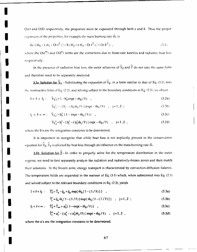
II
0(c) and 0(6) respectively, the properties must be expanded through both e and 6. Thus the proper
I\panrion of the properties, for example the n-ss burning rate m, is
fIrE1 +0 E ' in 2 +Cm13+ C 2 )r% 0D 2) , (3.1)
where the 0(rm) and 0(6n) terms are the corrections due to finite-rate kinetics and radiative heat loss
3 respectively.
In the presence of radiative heat loss, the outer solutions of 'F and T do not take the same form
and therefore need to be separately analyzed.
3.1a Solution for IF - Substituting the expansion of YF, in a form similar to that of Eq. (3.1), into
I th nonreactive limit of Eq. (2.2), and solving subject to the boundary conditions in Eq. (2.3), we obtain
I F,0if Yt : y =l-b~exp(-ffiO/i) ,(3.2a)
YF,=-Ib - (borph/rJ]exp(-rN)/i) , j=l,2 (3.2b)
if < i < : YF=b fI- exp(-ra/?)] , (3.2c)
i "+=b '-[ + - b_'"r /i)]exp(-ffno/i) ,j=1,2 ,(3.2d)
where the b's are the integration constants to be determined.
It is important to recognize that while heat loss is not explicitly present in the conservation
equation for YF, YF is affected by heat loss through its influence on the mass burning rate rM.
I 3.1b Solution for T - In order to properly solve for the temperature distribution in the outer
regions, we need to first separately analyze the radiation and radiatively-frozen zones and then match
their solutions. In the frozen zone, energy transport is characterized by convection-diffusion balance.
The temperature fields are expanded in the manner of Eq. (3.1) which, when substituted into Eq. (2.1)
and solved subject to the relevant boundary conditions in Eq. (2.3), yields
I l<i if : 0=is-4i+4:vexp{ ffi0[1-(1/-)] , (3.3a)
i % v [l(l )]xpff~~l(l/)] ,j=1,2 ;(3.3b)
if< i<-o : 0 ='F + a0 [ 1- exp(-i0 / i) ] (3.3c)
3 Tj=at-[a -(a r /)Jexp(-d/iv) , j=1,2 , (3.3d)
where the a's are the integration constants to be determined.
I

III
In the radiation region of 0(6), the coordinate is stretched as =r=(ir-if)/8 while the proper
temperature expansion is
T-Tf-6 6 1 (E7 /6 ) , - C8 3 -,- .] '0( 6 2 ) . (3.4
Substituting Eq. (3.4) and into the chermcally-frozen form of Eq. (2.1) and expanding, we obtain
d e/d; = - Ra exp( -87) , (3.5a)
d e /d,'=--Ra Wexp -8] , j=2,3 (3.5b)
where the small expansion parameter 8 is defined as 8=Tf/TaR while
Ra = 8 Ra exp( - T3,/'T.) (36) Iis a reduced parameter representing radiative heat loss. Thus energy conservation in the radiation
region is diffusion-radiation balanced.
Matching the solutions in the radiation and frozen regions as 7--if yields
Tf =s-qV+qvexp{mol -(1/ f)1 } , aO=(Tf-T.,,)/[1-exp(-o/if)] , (3.7)
and the boundary conditions needed to solve Eqs. (3.5) as --- , giving I<0: I
8-=21nil -[Ra/(go)jexp(goC +g )I -g 0 -gl , (3.8a)
K=- -f- T,+ )(r/0 1 -( 1 /if)1[ gO+2Raexp( - )]1 / 2 , (3.8b) Id63- ' 1 +Ra/go)Cexp(goC+gl)-{[lRa/(2go)]exp(goC+gl)}2.I .c
• .- =gorh, + r 0 f {l_[a/(2gO)]exp(goC+g,)}2
>0:
E =2ln1-[a/(2h 2 )exp(h 1 -h o0 )I +h 0C-hl , (3.9a)
@ = { a /h o ) 1-exp(_- m@/ f )I] + (Til if /ffi~o)j}[h 2 +a ex(-0 1/2(39 ),,1 + Ra xp( Ol(3.9b)
__ 2
1- (Ra/ho) C exp(h 1 -h 0 )-{ [Ra/(2 h ) Iexp(h-h 0 1)}2{ 1-Ika/(2h2)] exp(h l - hoC)}23.)
where
B8

I
I g T=( S f- rf-q)I0)/rf rh ( )( /?f2 ) exp ( - r./ti)/ [1 -ex F -rh o ) i
3 -, .i, , h I a2 1-exp - ro/if)I+(h0Ff M2 lo ) (3.10)
3-2 Inner Solution
In the reaction region of 0(c) thickness, the temperature is within an 0(c) reduction from the
maximum temperatureTf. The stretched spatial coordinate is =(r-f)/C while the temperature and
I fuel distributions are expanded as
I ~~0 0T-€O+( 6)+O( E7/ 5 1.]-2,O+0( 5)+0( /a)+...]+O( 3 C31
Y'F=-E 101 40 )+0F-/86)+.--] + C2[0 2 +0(6)+C( /6)+...+0(C ) (3.12)
3 Since oxidizer concentration is also an 0(e) quantity in this thin region, substitution of Eq. (3.12) into
Eq. (2.4) and forcing the leading order term to vanish yields
if = rno / In( 1 -'Y()- ) . (3.13)
3 Substituting Eqs. (3.11) and (3.12) as well as the stretched coordinate into Eqs. (2.1) and (2.2),
and expanding, we have two source-free equations expressing the local coupling functions and a third
I equation with the source term representing chemical reaction,
d , (3.14)
d2d d 1 mod- (3.15)
d -291
d21=Da 0l [ 01 - ( fil / r ) + ( fi/rho ) exp( - 01 )(3.16)
where the small parameter e is defined as e =Tf/TaK and
I a= E3 ( Da / Tf ) LeXP( -Ta,K / Tf) (3.17)
is a reduced Damkohler number. In obtaining Eq. (3.16), we have also used 1+0(e).
Equations (3.14) to (3.16) show that this region is reactive-diffusive. Radiative heat loss is not
I important here because its volume is much smaller than the total volume of the radiation region.
3.3 Final Solution
The boundary conditions required to solve Eqs. (3.14) to (3.16) are derived from matching the inner
B

I
and outer solutions as r -+f for YF and 0-*O for T. Upon matching, we first obtain b0 = 1 +Yo,, b=0 and
the solutions for m:n, a and bh. Next, the boundary conditions for the inner equations as are also
obtained. Integrating Eq. (3.14) twice and Eq. (3.15) once, and applying the proper boundary conditions, 3we obtain
(g+2 Ra )/ 2+(h6+2Ra)/ 2 =rht/ 2 , (318) I
and two additional relations to express b, in terms of a+ and ff. With these relations, o1 can be
expressed in terms of 01 as
0:1= {0 1 +[[rh1 /1n 1 + O,)]- } (h+2 Ra) 1 2 (3.19) ISubstituting Eq. (3.19) into Eq. (3.16) yields a second order, nonlinear ordinary differential equation
with 01 as the only unknown, subject to the matching conditions obtained. This equation needs to be
solved numerically.
The problem can I., ..odered to be completely solved at this stage in that all parameters to the
lowest orders needtd to solve the problem are either determined or are determinable through Istraightforwar' numerical integration. The solution includes three expressions, Eqs. (3.7), (3.13) and 3(3.18), wh4,h define the three bulk combustion properties of the flame temperature Tf, the flame-sheet
locatim n "7f, and the mass burning rate i 0 , in terms of the system, kinetic and radiation parameters.
Furthermore, solution of the differential equation Eq. (3.16), with 01 given by Eq. (3.19), determine the
parameters a+ and ri and consequently the condition for flame extinction.
4. RESULTS AND DISCUSSIONS
4.1 Re-Scaling
The solutions just obtained are not amenable for ready interpretation of the system behavior Ibecause the quantifying parameters 8, E, Ra and Da are all functions of the leading-order flame
temperature Tg, which in turn depends on the characteristics of radiative heat loss. It is therefore
necessary to re-scale all the parameters to a fixed, absolute reference state. Failure to do so could lead
to spurious interpretation of the results.
The obvious choice of the reference state is the adiabatic state. Designating properties of this I
B1O 3

UI
state by the superscript *, we haveTI T- Y , - Y (4.1)
f =ln{ I+[ ,,- T,)/qv (4.2)
= n Yo, (4.3)
The parameters referred to this adiabatic, reference state can then be expressed as- 3
29 , 2 ~
Da = C Da exp( - ,K/T( )/T - , E*=Tf /TaK
Ra" = 8' Ra exp( - -a, R/I ) " T; T; 2/T (4.4)
3 With the expressions in Eq. (4.4), the system dependent parameters can be rewritten as
Da = Da(T T/T )4 exp[ T, K ( T -Tf )I , (4.5)Ra = Ra" (T/f )2 exp[ Ta -R]T- )] , (4.6)Ra =hile a * ( T-'f T- T " - -T (4.6)
Iwhile a+=(Tf/Tf )-aj is obtained from Eal =c a, and a similar expression can be obtained for rnj .
Since Da and Ra, and hence Da" and Ra , vary with the droplet size in the same, quadratic,
manner, we can define a parameter Fl=Ra i/a ° , which is the ratio representing the characteristic
reaction time to the characteristic radiation time. It depends only on the kinetic and radiation
I constants of the system.
3 In addition to the need for re-scaling to an absolute reference state, it is also necessary to clearly
identify the roles of the various dependent and independent parameters in their dimensional and
3 nondimensional forms. Of particular importance is the droplet size, r5, which has been extensively used
in nondimensionalization. For example, an increase in the (reduced) Damkohler number Da can be
I interpreted as either an increase in chemical reactivity or an increase in the droplet size. Similarly, an
increase in the heat loss parameter Ra can imply either an increase in the loss intensity or an increase
in the droplet size. Thus a clear measure of the relative influence of reaction and radiation is the
parameter F, in which the droplet size is divided out. The problem is defined by using any two of the
three parameters E)a*, Ra and r.
It is further found that the final structure equation of the present system can be converted to that
of Li~inI by re-scaling the various parameters and variables as
1 BI

I
6a c i 3 01 - yT , c41Da*( Tf/Tf) 4 [- [/ln( I , Y)1 2 exp[taK(Tf- -Tf 1')]I
T (XI /2)[In l Y-' ,-rnjj/-rf , =I-[2if/ln(l+YO,.)](g -2Ra)
The structure equation, Eq. (3.16), is then reduced to that of Lifin, given by
(62- ( ) exp[ -a - + Yq ) 1 = 1 (4.7)
dO( 2 -)x- 1 1 0,ddOlyfllK -lkQ ' IlThe quantities a and rm1 can be determined from solving Eq. (4.7) as 3
5 aYo I/( I + Y 0o) cc-/(Tf/Tf )2[h/(hN+2Pa) /2I lim ((-71) , (4.8)
- /3 2 1/ 2 - - Ir=-{r cc n(IY' /[f(g -2Ra) I }(Tf/ Tf Y lim ( +T) (4.9)
Equation (4.7) has been numerically solved by Lifidn.1 Results show that extinction is expected for
U< c, where XE is approximately given by
C(E=e[(l-IyI)-(I-ly')2+0.26 (1-yiy)3+0.055 (1-h'y)I ] (4.10)
with very good accuracy. It may be noted that in the presence of radiative heat loss, y varies with cc
through Da ° for fixed F and therefore cannot be independently specified.
We mention in passing that Sohrab et al. 4 assumed complete reaction so that there is no reactant I
leakage through the flame. This means that in addition to the required boundary conditions to solve
Eq. (4.8), the additional constraints (O+rl) .=(0-f)c=0 are applied, which renders the problem over-
determined. 34.2 Results
To demonstrate the salient features of the solution, the combustion of a heptane droplet at its 3boiling temperature and burning in the standard atmosphere is solved. The system parameters adopted
are
Ts=372K , Tw=298K , TaK=22,000K , Ta,R=8,O K , cp=0.317cal/gim-K ,
qF=1Okcal /gm , qv=75.8cal /gm , (voWo)/(vFWF)= 3 5 2 , YO = 0 232 .
We first present the flame characteristics when the reaction zone is infinitely thin and reactant 3leakage is suppressed. The flame is still of finite thickness due to radiation broadening. The
B12 3

I
combustion parameters Tf, i, and rFf are given by the three algebraic expressions Eqs. (3.7), (3.13) and
1 3.18), which can be iteratively solved together with the scaling relation Eq. (4.6).
Figure 1 shows the flame temperature "f and mass burning rate rf) as functions of Ra*. The flame
radius Ff is not shown because it is directly proportional to Fno. It is seen that Tf and m0 both decrease
with increasing Ra. Thus for a fixed droplet radius r., increasing radiative loss intensity reduces the
flame temperature and mass burning rate, as expected. However, if we interpret the increase in Ra as
due to an increase in r., with fixed radiation parameters, then we should also account for the fact that
the physical burning rate m 0 varies linearly with r. Then the numerical values show that no still
I increases with r,, albeit at a slower rate in the presence of radiative loss.
3 Since the reaction rate is assumed to be infinitely fast, extinction is not described at this level of
solution. Consequently Fig. I does not exhibit the extinction turning point behavior. To allow for finite-
3 rate kinetics, Eq. (4.7) is solved numerically. Figure 2 plots a versus Da* for several values of Ra,
where a represents the temperature reduction due to incomplete reaction and is directly related to the
I amount of fuel leakage through the flame.
We first discuss the adiabatic limit, Ra =0, which corresponds to y=0.867 for the present system.
This is the situation studied by Lifin. It is seen from Fig. 2 that there exists a minimum Da , DaEK,
such that there is no solution for Da* < DaEK and there are two solutions for Da' > 5aEK. Thus ba K can
be identified as a (reduced) kinetic extinction Damk6hler number. The lower branch, which shows a
I decreases with increasing Da*, is the physically realistic solution.
To investigate the influence of radiative heat loss, it is important to specify the process/
parameter which is held fixed in the comparison. To demonstrate this point, in Fig. 2 the effect of
radiation is exhibited by plotting - versus Da on constant Ra . Since both Da and Ra depend on the2 2
droplet size through r., r; should be considered as a fixed quantity in the comparison. Figure 2 then
shows that, for a given reference reactivity Da*, increasing radiative loss through Ra" increases the
extent of reactant leakage. This is reasonable because of the reduction in the flame temperature and
thereby reaction rate due to the heat loss. The kinetic extinction Damk6hler number is consequently
3also increased. By the same reasoning, we see that for a given radiative loss Ra, increasing reactivity
B13

)a reduces the extent ot leakage
Vliire 2 is rvcv ant tor stud ving th e1('ct t ect t ch11an g InTg t h ce t i(/o x id i , cr s v teL-ii e ( C i I-,',I t i tu tion, oid i zr enrich ment) (m a droplet ot t I sd 'd t', 110o wevir, treo uien tI v a m( rt rc, In t
quetion to a,k i" the ettect of varving the droplet si /t for a fixed fuel/oxidizer systen. For example,
alter a fuel droplet or particle has achieved ignition, the droplet size r, will stcadilv decrca ,' 3altlwingh its phy'sicail tlane si/c r, can tirt increase, due to fuel vapor accumulation, and then
dco. rease. Th, relevant plot to demonstrate droplet siue effects is again a versus Da , but on constant , Ia shown in Fig. 3. For such a plot we can consider the reference chemical reactivity to be tixed. Thus
tor a giVeln D)a in( reai g 1 increaeL'S the it Iec of radiation, while for a fixed V inerca i ing Da
implies increas,'g values of r,.
Figure 3 shows that, for smaller values of Da , the flame response is qualitatively similar to
that of Fig. 2, exhibiting the turning point behavior at DaEK. The behavior, however, becomes Iqualitatively different for larger values of Da . It is seen that by continuously increasing Da along the
lower branch of a constant F curve, the reactant leakage first decreases and then increaes until another Uturning point is encountered. According to our earlier discussion and anticipation, this turning point 3should represent an alternate mode of extinction, namely extinction due to fuel leakage in the presence
of excesi.,ive radiative heat loss and flame temperature reduction for large droplet sizes. We therefore
designate this critical state as that of the radiation extinction Damk6hler number, DaaR. It may be
emphasized that this mode of extinction is caused by the slow kinetics due to the heat loss but not the Iloss itself. Thus steady burning is possible only for ba LK< Da< 6aFR. This range in Da* is further
diminished with increasing F (Fig. 3) such that there exists a maximum F, say Fc , beyond which burning
is absolutely not possible, for the fuel/oxidizer system, regardless of the droplet size. I
In Fig. 4 we have plotted the extinction Damk6hler number )ai and the corresponding flame
temperature as a function of F. This curve can be generated directly by using Eq. (4.10) with the proper Idefinitions of c and y. Thus for a given r, the possible values of Da" are bounded by the upper and
lower branches of this curve, which respectively represent the kinetic and radiative extinction
Damk6hler numbers 1ajK and 6ajR. The maximum value of r ib found to be Fc=0.0302 for this model 3
B14 3

I
system. It is also seen that the flame temperature reduction is small for the upper, kinetic extinction
regime, but is substantially larger for the lower, radiative extinction regime, as is reasonable to expect.
It is of interest to estimate the characteristic radiative extinction droplet size. Such an
estimation requires values of X and BR. For X we used 2 .9 7 x1 O"4 cal/cm-sec-K, which is that of air at
3 2,000K. To estimate BR, we first fitted T4 in the temperature range of 1,600K_<T<2,500K to yield14K4'
T4 =8.90x10 14exp(-8,000K/T) K Next, the Flanck's mean absorption coefficient is taken as the molar
3 averaged value of the mixture in the radiation region. Since the amount of reactants is small compared
to that of the products in this region, it is reasonable to consider that the mixture consists of CO 2, H20
I and N,. Furthermore, since N 2 is verv non-radiative as compared to CO2 and H2 0, we have
K Xco2Kco2+Xti20K11 2O. Using 6 KCO 2 = 5.63x10 2 cm 1 and KH20=7.13x 10 3 cmI evaluated at 1 atm and
2,00OK, and xco =0.124 and xlI 20 =0.142 for the stoichiometric burning o' heptane in air, we obtain
3 K=8.00X10 3 cm -1. Using x, (T and the fitted T4 , BR is determined as 3.87x10 3 cal/m3-sec and
consequently Ra =(28.2 m' )r, with Tf calculated from Eq. (4.1).
I Experimentally, n-alkane droplets burning in air typically extinguish, in the kinetic limit, in
the range around rsEK=.1 mm. This yields RaLK= 2 .8 2 x1 0-7 . Using this value and the relation
DaEK= RaEK/F, Fig. 4 shows that there is no solution even with the maximum F of 0.0302. Therefore
the flame cannot exist at all. This result obviously contradicts experimental observations because
n-alkane droplets can be routinely burned in room air. The cause of this discrepancy is believed to be
3 the excessively large flame size predicted by the theory. That is, it is well established 5 that because
of the unity Lewis number assumption and the neglect of the fuel vapor accumulation process, the
classical d -law solution, which is the leading order solution in the present problem, predicts
3 flamefront standoff ratios for n-alkane droplet combustion in air to be typically 40. Experimentally 5
the ratio is more in the range of 5 to 10. This large theoretical flame size then leads to excessive
3 radiative heat loss and thereby promotes radiation-induced extinction. Since radiative heat loss
scales with , , this effect can be approximately accounted for by reducing RaFK by the square of the
I ratio of the experimental to the theoretical flame size. If we take this ratio to be, say 6, then through
3 iteration we find 5a K=4.67x10 7 and r=0.0167, which yields a radiative extinction droplet size of
B15

II
rsER = 0.93 mm. This value is about 10 times larger than the kinetic extinction droplet size. It is
reasonable to expect that in the presence of soot the value of rs,E,R could be further reduces to render
radiative extinction an important process in heterogeneous combustion.
5. CONCLUDING REMARKS
In the present study we have successfully analyzed the structure and extinction characteristics of
diffusion flames suffering radiative heat loss from the flame, when the thickness of the radiation zone 3is asymptotically intermediate of those of the reaction zone and the bulk flow field. Perhaps the most
interesting result from the present study is the identification of the existence of dual turning points. ISpecifically, by fixing the thermochemical aspects of a fuel/oxidizer system, we have shown that
steady droplet burning is possible only for droplet sizes within a certain range. Extinction of smaller
droplets is caused by purely finite-rate kinetics, while extinction of larger droplets is caused by 3excessive radiative heat loss which eventually again leads to the kinetic limitation. The range of
droplet size for steady burning narrows with increasing radiation intensity, as represented by the 3parameter F, such that droplet burning is not possible beyond a certain critical Fc .
Extension of the present results to other quasi-one-dimensional flow configurations is
straightforward, involving primarily changes in the definitions for Da and Ra to account for the 3different expressions of residence times.
Acknowledgements UThis research performed at Princeton University and Case Western Reserve University were
respectively supported by the Division of Basic Energy Sciences of the U. S. Department of Energy under
Contract No. DE-FG02-89ER13988, and by the U. S. Air Force Office of Scientific Research under Grant 3No. 85-0340.
B16 3

I
1. Lifin, A. : Acta Astronautica 1, 1007 (1974).
2. T'ien, J. S. : Combust. Flame 65, 31 (1986).
3. Sibulkin, M. : Prog. Energy Combust. Sci. 14, 195 (1988).
4. Sohrab, S. H., Lieiin, A. and Williams, F. A. : Combust. Sci. Tech. 27, 143 (1982).
5. Law, C. K. : Prog. Energy Combust. Sci. 8,171 (1982).
3 6. Abu-Romia, M. M. and Tien, C. L. : Trans. ASME 89, Ser. C J. Heat Transfer, 321 (1967).
APPENDIX
Broadening of Radiative Diffusion Flames
3 With the flame sheet located at ft and having a temperature Tf, the temperature and fuel
distributions can be solved. Since both the fuel and oxidizer have to be totally consumed at the flame
sheet, we obtain from Eq. (2.4) ff=ri /In(l+Yo.). Evaluating the temperature at the flame sheet
yields
If = T,-qZ,. +,,exp{ r[ -( 1 / if) } (A.1)
3 The jump relations can be obtained by integrating Eqs. (2.1) and (2.2) once across the flame sheet,
yielding
if 2[(dT / c )- (d -/cE')]r=-l1+12 , f (dYF/ d;=-I 1 , (A.2)
where the superscripts - and + respectively denote the fuel and oxidizer side, and
j2 rf-2- 2 YF~x(TKTd lRa jr
1,(Da/Tf )j_ r 2YFYOexp(-Tr,'K/T ,d ' 12=R _r exp(-i.aR/t)dirfrf
Substituting the solutions of Tf and YF into Eq. (2.6) gives
I n { ,. + Y'0,..- ", + 4, [ I - exp(i)I } = ' 12 (A.3)
and I,=rfi. It is seen that there are three unknowns, ffi, TF and 12, which need to be determined from the
two relations of Eqs. (A.1) and (A. 3). The problem is therefore not closed.
II

!I
Figure 1. Variation of the flame temperature T, and the mass burning rate mo with the radiative heat
loss parameter Ra*. The inset is a schematic defining the problem analyzed.
Figure 2. The extent of flame temperature reduction or reactant leakage as a function of Da* for fixed
values of Ra". 3Figure 3. The extent of flame temperature reduction or reactant leakage as a function of Da" for fixed
values of r. IFigure 4. Extinction Dankohler number DaE and flame temperature Tf,E as functions of the radiation 3
heat loss parameter F.
BIUUI
IU
IU
BI8 U

II
II
I0 *
I B19

Ii!
II
i~ I
× I -
tN U
B20I

II3III*I
I ue~*II*II
NI I I I I I0 e~J 00 0Cl
'(U
I3 B21

II
10-
Non-Combustible i
-710 -3_
--- 'fE Tf, E,KI
10. -~ 6i-- TfER ¢
Combustible
I "
1--4
10.7 I I c
0 0.01 0.02 0.03 1r 1
B22

IIIII
Appendix C
IIIIIIIIIIII
Cl
I

II
Submitted to International Journal of Heat and Mass Transfer
III
DIFFUSION LAYER STRUCTURE IN A THERMOPHORETICALLY
AFFECTED FLOW OVER A HOT SURFACE II
by3
INoureddine Ait Messaoudene and James S. T'ien 3
Department of Mechanical and Aerospace Engineering
Case Western Reserve University ICleveland, Ohio 44106
U. S. A.
IIII

II
Abstract
A theoretical analysis is performed to study the
distribution of small-size particles in a flow adjacent to a
hot wall. Because of the thermophoretic motion, a particle
stagnation point is created in the interior of the flow which
can produce singularity when particle diffusion is neglected.
By including Brownian diffusion and using matched asymptotic
expansions, the structure of the inner diffusion Iayer near the
particle stagnation point is resolved. The presented results
illustrate how the diffusion layer is evolved and its
structural variation with a number of parameters.
CI
IIIII
Il C3

II
I. Introduction
Thermophoresis is the motion of small particles
relative to their containing gas induced by a temperature
gradient (1, 2]. Because of the existence of thermophoretic
velocity, particle concentration distribution can have unusual
characteristics which requires special analysis. In the
presence of a cold wall, the thermophoretic motion drives the
particles toward the wall which affects their deposition rate.
In most theoretical works concerning deposition rates, e.g., 3Refs. [3-7], particle diffusion is neglected. This is because
the diffusion coefficient is very small which, in the case of a Icold wall, will have only negligible influence on the particle
convective flux toward the wall. The neglect of particle
diffusion, however, lowers the order of the differential
equation of the particle concentration equation. Therefore,
the concentration structure in the thin layer next to the wall Icannot be studied. Walker, Homsy, and Geyling [8] included
Brownian diffusion in their analysis of thermophoretic
deposition in flows inside a cold tube. The structure equation 3is solved using matched asymptotic expansions. They found,
however, that because near the wall the fluid velocity is Inegligible while the thermophoretic velocity is finite, the 3wall particle deposition rate is unaffected by the diffusion
layer. 3
Ic4 3

I
For a hot wall, the thermophoretic motion drives the
particles away from the wall. When particle id",_on is
neglected, a particle stagnation point (or surface) is created
and a dust-free layer adjacent to the surface is Drpdicted [3,
I 7, 9, 11]. For low Mach number flow, Goren [3] is the first to
show that when the product of thermophoretic coefficient (K)
and Prandtl number (Pr) is less than unity, the particle
concentration drops to zero quickly at the particle stagnation
surface. But when KPr is greater than unity, a singularity
I occurs - the particle concentration becomes unbounded at the
particle stagnation surface. Since in both cases, the
concentration gradients become very steep, particle diffusion
* can become important even when the diffusion coefficient is
small. For the case KPr < 1, analysis [11] has been performed
for incompressible flow (small temperature difference and low
Mach number) including diffusion to assess the degree of
particle leakage across the particle stagnation surface. But
for KPr > 1, the more severe case for the solution misbehavior
(singularity), no remedy has been given.
In this work, a theoretical analysis is given for the
particle concentration distribution in a low Mach number,
compressible flow over a hot wall. Particle diffusion is
included. By using the particle Schmidt number as the large
parameter, an inner-outer expansion technique is employed to
* study the particle diffusion layer structure for both the cases
I

II
of KPr greater than unity and less than unity.
II. Governing Equations I
The flow to be analyzed is the axisymmetric
stagnation-point region of a heated plate as shown
schematically in Fig. 1. Experimentally, this configuration
can be created either by impinging a jet perpendicularly onto a
plate or by placing a blunt body in a windtunnel. The small
particles are seeded in the upstream. Fig. 1 shows the
existence of two stagnation points: a gas flow stagnation
point on the plate surface at x = y = 0 and a particle
stagnation point at x = 0 and y = y (-q = T). The presence of
the particle stagnation point in the interior of the flow field
is a result of the particle thermophoretic motion away from the Iheated plate. To analyze the structure of particle
concentration around this particle stagnation point is the
objective of this work.
The equations governing the low speed flow (Mach
number square much less than unity) in the axisymmetric
stagnation-point region are given by the compressible boundary Ilayer equations:
apux + 8pvx = 0ax ay (
ax v3 - ax a au (2)
I

II
IU T+PC a aT] 0 (3)P j _ p a y -Y 'j Y JI
1 ia a a- -xpuY + --PV Y = ! (4)x ix -Y P
where Eqs. (1) - (3) are the conventional continuity, momentum
and energy equations respectively. The pressure gradient term
- in Eq. (2) is equal to - pue u e/ax and the x-component
-- free-stream velocity is given by
u = ax (5)Iwhere a, the velocity gradient, is the parameter characterizing
the flow. Eq. (4) is the mass conservation equation for the
particles. In Eq. (4) , Y is the mass fraction of particles, v
is the particle velocity which is the sum of gas velocity (v)
and thermophoretic velocity (Vt):
v = v + V (6)Ip t
The expression for the thermophoretic velocity is:
v = -K(g/p)VT/T (7)
where K is the thermophoretic coefficient whose magnitude
depends on the regime of the flow [12). The value of K
I normally taken is between 0.2 and 1.25 and in the present study
C-- C7

II
it is treated as a parameter.' The last term in Eq. (4)
represents particle (Brownian) diffusion and D is the diffusion
coefficient which is normally very small. l
The boundary conditions for the flow and the 3temperature fields are:
y = 0: u = v = 0 , =T (8)w I
y- : u=u , = T C (9)e Iand for the particles:
y 0: Y= 0 (10)
Y : Y = YM (11) 1
The condition of Y = 0 in Eq. (10) is the result of assuming 3that we have a "sticky" wall that will act as a perfect sink
for the particles [15]. The condition of Y = Y in Eq. (11)
indicates that the particles are seeded in the free stream. To 3proceed further, the following assumptions are addpq: I
1. the gas obeys ideal gas law and the product pg is
a constant, 3
Experimental determination of K is a difficult task [13]. Anovel measurement technique using counterflow diffusion flameshas recently been suggested (14).
I

II
2. gas heat capacity C , the thermophoreticP
coefficient K, and the Prandtl number Pr are
constant,
3. the mass fraction of particles is much
smaller than unity which does not affect the
overall continuity equation,
I 4. the Schmidt number (based on Brownian
particle diffusion coefficient) is constant,
I 5. the particles are of uniform size and inert.
There is no particle chemical reaction,
nucleation, condensation, coagulation or
break-up.INext, the Howarth-Dorodnitsyn transformation for
compressible boundary layer is introduced:
I=V fypdy and s = TPe1X 4 (12)P e 9e 0
u = u f and v = p "a f (13)
where s and n are the transformed x and y coordinates and f is
a modified streamfunction. Using Eqs. (12, 13) and introducing
nondimensional temperature e (= T/T.), Eqs. (1-3) become:
I 2 (15)
1tr-- + fe" = 0 (16)
I3 c9

II
where superscript - denotes d/dn. I
The boundary conditions (Eqs. (8-9)] give
7 = 0: e = e f f " = 0
e W 1 2(17)7 -* : & = 1 f" = 2 IFor the particles, Eq. (4), with Eqs. (6-7), is transformed
into:
1-- IcY + V(n)Y + F(77)Y = 0 (18)
Iwhere
V ( ) = f + K e e ( 1 9 )
F(71) = K(ee - 2" )/e2 (20)
Equations (15-17) can be solved first. The velocity Iand temperature fields obtained can then be used in Eq. (18)
for the solution of particle mass fraction. The decoupling of
particle distribution from the flow field computation is the
result of assumption of dilute particle concentration. We will
now concentrate on developing the analytic solution for Eq. 3(18) subject to boundary conditions (10-11). For particle size
ranging from 10 nm to a micron, the Schmidt number is typically
high and will range from 102 to 10 6 [13]. Therefore, 1/Sc can 3
ICl0 I

I
be regarded as a small parameter in Eq. (18). The quantity V
in Eq. (18) represents the particle velocity. As shown in Eq.
3 (19), V consists of a gas flow component f and a thermophoretic
component Ke'/O. In this problem, f starts with zero value at
I 7 = 0, increases monotonically as n increases and e" is
3 negative at 7 = 0, increases with 'n and reaches zero at large
1. Thus at some location above the heated plate, denoted byi, V is equal to zero. This is the particle stagnation point.
As shown schematically in Fig. 1, on one side of rn , V is
i positive and on the other side, it is negative, i.e., V changes
s ign at -T . Using 1/Sc as the small expansion parameter, Eq.
(18) constitutes a singularly perturbed differential equation
with a turning point [16-19].
3 III. Analysis
3 The analytic solution for Eq. (18) with boundary
conditions (10-li) will be presented in this section using the
3 matched-asymptotic expansion technique (20-21].Equation (18)
gives rise to two regions using the perturbation method: an
I outer region where only convection (including thermophoresis)
is important, and an inner region near 71 where diffusion is
also important.
i Outer region:
Diffusion is negligible and Eq. (18) becomes
i3 Cll

III
V(T)Y' + F(7)Y = 0 (21)
Applying the boundary conditions, the solutions are: 10 < T1 < T? , Y = 0 (22)
7 Y -exp F ()d77 (23)nY > n ' V(71)CO T? U
In 71 > 7 , V(77) > 0, Eq. (23) shows that if F(T ) < 0, Y(1 )
0 which matches the value from Eq. (22) although the gradients idY/d7? are not continuous at T . If, however, F(17) > 0, Eq.
(23) indicates Y(7 )/Y becomes unbounded. Appendix A sh)ws
that the sign of F(71) depends on the value of the product of
Prandtl number and thermophoretic coefficient: F(7 ) 0 if
KPr 1. When KPr > 1, the other solution is singular at the
particle stagnation point. This singularity can be removed in
the inner solution where particle diffusion is included.
Inner region
In order to simplify the analytical treatment we 3first consider a region of thickness 2A7 around i" in which
V(r) and F(n) can be linearized. Eq. (18) can be rewritten as:
1Y + (i - )V'(i'¥ + [F(7) + (n - 71)F'(-q) Y = 0 (24)
I
C12 3

II
upon changing the variables to
this becomesI2d Y dY
+(A + B =)Y 0 (25)
3with boundary conditions3Y(-I) = 0 ; Y (+1) = Y
where
1 1/= i/[ScA 2v " (T')]
i A = F (')/V(77)
I B = A)F(n.)/V (71) (26)
YI = Y exp F ()~75)+
and = 0 corresponds to 1 = q • Near 7 , V(TI) 0 and the
first term in Eq. (25) can only be balanced by the last term so
that an inner layer of thickness -0(VE) will exist. Outside
this inner layer and in -1 < C < + 1 a linearized outer
Isolution will be given by3 Y = 0 for -1 5 < 0
3C13

IU
Y = Y.ICA-exp[-B( -I)] for 0 < E < + 1 (27)
which can be rewritten in terms of n: NA r
Y = GlI-770 exp[- Cq T7T (28)
where
G = Y AT AeB
and it can be shown that G is independent of the choice of An
within the neighborhood of n [21]. Note that we must have
A77> 6, so that from the definition of c in Eq. (26) we get II
(ScV (71) Y251Now we introduce a stretched variable, v = IVJ, to transform
Eq. (25) into 3
d 2 Y + , d- + AY + = (V2 dvAY + vfcB Y =0 (29)
since c is a small parameter Eq. (29) can be approximated by
dY + C+AY= (30) 3I
C14 I

II
I The general solution to Eq. (30) is
-Y = e V2/4[CIDA-1 (v) + C2D_A (iv)] (31)
Iwhere the D's are parabolic cylinder functions [23] and C I C
I constants of integration.
Using the matching principle described in [20, 21]
the asymptotic expansions of the D's [23] and the boundary
3 conditions, the following composite expansions are obtained:
- 5 :5 0 (r- < qi)
Y_( ) = Y+1 exp(B) (V)-Aexp(_C2 /4c)
-F(1-A) exp[(1-A)) ri]D_, [CV +) + AD-A V (32a)
! 0 -7 1 ( > n),
Y. (C) =Y. exp(B) ( VC) -Aexp(- 2 /4c) 1A)e 1-)i]DA-
II / _2TLL)JA1 / J
+ i A DA( i/vEc)] + Y' exp(B) (C) -A 1exp(-BC)-1] (32b)
and using the fact that
C
i c15

ID_ n(iZ) _ ~-) exp(n7Ti/2)D _(Z) + exp -n7 i- - Dn (-Z)] (33)l
we obtain:
Y () = Y) lexpp(B)((V 4) (-/vU) (34) 1
and I
Y.() = Y () + Y+1 exp(B)( )-A[exp(-B ) - i] (35) 1
this can be rewritten in terms of 71:
Y (TScV() ( G(( 1-A) exp
(ScV (1 (_7 )2
I
Y. (-0) = Y-(-q) + G (7qT) -A exp[- V'(71) (T-1 "~]i (37)1
Eqs. (36-37) give the particle mass fraction profile
in the diffusional inner layer near the stagnation point.
Together with the outer solution, Eqs. (22-23), they give the 1
IC16 3

II
3 complete distribution of particle mass fraction in the flow
field. To see that the singularity at the particle stagnation
I point is removed, we get from Eq. (36) or (37):
Y(i ) = G 2ScV(71) A 2 r(I-A/)I I•F1A2From the above expression, we see that Y(7 ) will
grow as (/SC 3. For any finite value of Sc, Y(77) will be
bounded. In the physical systems, Sc will be finite and the
* present analysis is valid for values of Sc up to about 106.
Beyond this value the inertia of the particles may become
I important.
I IV. Discussion
3 In this section, selected graphical presentations
will be given for the analytical solutions just obtained. This
I is to illustrate the importance of Brownian diffusion near the
* particle stagnation point especially when the product of
thermophoretic coefficient and Prandtl number is greater than
3 unity.
Fig. 2 shows the particle mass fraction profiles near
the stagnation point () as given by Eqs. (36) and (37) for Sc
3 = 10s, Pr = 1 and KPr = .6 and 1.5. Also shown in the dashed
lines are the solutions with diffusion neglected. For KPr < 1,
we see that particle diffusion modifies the concentration
I3 c17

Ii
profile--there is a leakage through the stagnation point and 3the concentration gradient drops smoothly toward zero. This is
similar to finding in Ref. 11. More drastic is the case for IKPr > 1 (= 1.5). The dashed curved in the bottom half of 5Fig. 2 shows that without considering diffusion, the mass
fraction becomes unbounded at the stagnation point. When 3diffusion is included, however, a peak of Y/Y occurs slightly
upstream of the stagnation point n , the particle concentration
then drops steeply, passing through n , to zero. Thus, we see
that particle Brownian diffusion, although having a very small
diffusion coefficient, produces drastically different 3concentration profiles when KPr is greater than unity.
Fig. 3 shows the particle profile as a function of * 3from the wall boundary to the free stream for Pr = 1, K = 1.5
(Pr x K = 1.5) and Sc. = 104 . In this figure, not only the
inner solutions and also the full range of outer solutions are 3utilized.
In Fig. 4 the particle mass fraction profiles near 3their stagnation plane are shown for Sc ranging from 10
2 to 106
for Pr = 1 and K = 1.5. As Sc increases the peak sharpens, the Ipeak value increases and the peaking location moves closer to 31.
Fig. 5 shows the particle mass fraction profile for 3different values of K for Sc = 104 and Pr = 1. We see that
with the introduction of Brownian diffusion the behavior of the Ui
C18 3

II3 solution changes monotonically and smoothly as KPr changes from
values less than one to more than one. We also see that as K
I decreases, the particles stagnation plane moves closer to the
hot boundary due to the decrease in thermophoretic velocity.
The analytic solution given by the asymptotic
3 expansion has also been compared with direct numerically
integrated solutions of Eq. (18). For Sc = 102 to 104 the
* solutions from the two methods are practically
indistinguishable. As expected, the asymptotic solution breaks
down for moderate values of the Schmidt number. At Sc = 10 the
3 difference between numerical and asymptotic solutions becomes
appreciable and in the analytic solution a slope discontinuity
I at 71 becomes visible due to the limit of validity of the
expansions of the D 's. Direct numerical solution of Eq. (18)
for Sc beyond 10 4 becomes increasingly difficult because of the
3 demand of increasingly smaller grid size.
IIIIII3 c19

II
Nomenclature3
A = F(i ))/V (T)
a stagnation-point potential flow velocity gradient IB = A-F" (*)/V(77.)
F defined in Eq. (20)
G defined in Eq. (28) 3f nondimensionalized stream function
K thermophoretic coefficient IPr Prandtl number 3Sc Schmidt number
T absolute temperature 3V nondimensional velocity Eq. (19)
Y particle mass fraction, (mass of particle/unit Ivolume)/(total mass of gas and particle/unit volume)
y distance away from the heated wall 3Greek Symbols 3
coefficient of dynamic viscosity
p density
n similarity variable Eq. (12) 3e T/T , nondimensional Temperature
5 concentration inner layer thickness
Oar - 7) All
v stretched variable
c small parameter, see Eq. (26) I
IC20 3

I
3 Nomenclature (continued)
3 Subscripts
3 t thermophoretic
e boundary layer edge
IO free stream conditions
i _ 77 < 77
+ 77> 7
I Superscripts
3 particle stagnation plane location
Ii
IiIiI
3 C21

II
Acknowledgement 3
This research has been supported by the United States 3Air Force Office of Scientific Research through Grant 85-0340.
AMN would also like to acknowledge support fron the Ministry of 3Higher Education of Algeria.
IIIII!!IIII!III!
C22 3i

UU3 References
1. Friedlander, S. K.: Smoke, Dust and Haze, Wiley, Hew York~(1977).
2. 7albot, L. Thermophoresis - A Review, in Rarefied GasDynamics, Part I (Edited by S. S. Fisher), Prog.3 Astronaut. Aeronaut, 74, 467-488 (1981).
3. Goren, S.: Thermophoresis of Aerosol Particles in theLaminar Boundary Layer of a Flat Plate, J. of Coll. andInterf. Sci., 61, 77-85 (1977).
4. Batchelor, G. K. and Shen, C.: Thermophoretic Depositionof Particles in Gas Flowing Over Cold Surfaces, J. ofCoil. and Interf. Sci., 107, 21-37 (1985).
5. Shen, C.: Thermophoretic Deposition of Particles ontoCold Surfaces of Bodies in Two-Dimensional andAxisymmetric Flows, J. of Coll. and Interf. Sci., Vol.1127, No. 1 (1989).
6. Homsy, G. M., Geyling, F. T., and Walker, K. L.: BlasiusSeries for Thermophoretic Deposition of Small Particles,KJ. of Coll. and Interf. Sci., 83, 495-501 (1981).
7. Garg, V. K. and Jayaraj, S.: Thermophoresis of AerosolParticles in Laminar Flow Over Inclined Plates, Int. J.Heat and Mass Trans., Vol. 31, 875-890 (1988).
8. Walker, K. H., Homsy, G. M., and Geyling, F. T.:Thermophoretic Deposition of Small Particles in LaminarTube Flow, J. of Coll. and Interf. Sci., 69, 138-147(1979).
9. Gokoglu, S. A. and Rosner, D. E.: Prediction and RationalCorrelation of Thermophoretically Reduced Particle MassTransfer to Hot Surfaces Across Laminar and TurbulentForced-Convection Gas Boundary Layers, Chem. Eng. Comm.,Vol. 44, pp. 107-120 (1986).
10. Stratman, F., Fissan, H., Papperger, A., and Friedlander,S. K.: Suppression of Particle Deposition to Surfaces bythe Thermophoretic Force, Aerosol Sci. Technol. 9, 115-1213(1988).
11. Friedlander, S. K., Fernandez de la Mora, J., and Gokoglu,S. A.: Diffusive Leakage of Small Particles Across theDust-Free Layer Near a Hot Wall, J. Coll. Interf. Sci.,125, 351-3 5 (1988).
I3C23

I
12. Talbot, L., Chen, R. K., Scheffer, R. W., and Willis, D.R.: Thermophoresis of Particles in a Heated BoundaryLayer, J. of Fl. Mech. , 101, 737-758 (1980).
13. Flower, W. L.: Measurements of the Diffusion Coefficient ifor Soot Particles in Flames, Physical Review Letters, 51,2287-2290 (1983).
14. Gomez, A., Smooke, M. D., and Rosner, D. E.: Application iof Counterflow Diffusion Flames to the Determination ofParticle Thermophoretic Diffusivities, Eastern StatesSection Meeting, The Combustion Institute, Gaithersburg,Maryland (1987).
15. Gokoglu, S. A. and Rosner, D. E.: Thermophoretically 3Augmented Mass Transfer Rates to Solid Walls AcrossLaminar Boundary Layers, AIAA Journal, 24, 172-179 (1986).
16. O'Malley, R. E.: On Boundary Value Problems for aSingularly Perturbed Differential Equation with a TurningPoint, SIAM J. Math. Anal., F, 479-490 (1970). 3
17. Grassman, J. and Matkowski, B. J.: A Variational Approachto Singularly Perturbed Boundary Value Problems forOrdinary and Partial Differential Equations with Turning IPoints, Ibid, 32, 588-597 (1977).
18. Kresiss, H. 0. and Parter, S. V.: Remarks on SingularPerturbations with Turning Points, Ibid, 5, 230-251(1974).
19. Pearson, C. E.: On a Differential Equation of Boundary 3Layer Type, J. of Math and Phys., 47, 134-154 (1968).
20. Nayfeh, A. H.: Perturbation Methods, Wiley Interscience(1973). i
21. Van Dyke, M.: Perturbation Methods in Fluid Mechanics,Academic Press (1964).
22. N. Ait Messaoudene: Particle Distribution Near theStagnation Point Induced by Thermophoretic Motion With and IWithout Combustion, Ph.D. Thesis, Case Western ReserveUniversity, January, 1989.
23. Abromwitz, M.: Handbook of Mathematical Functions, Vol. I55, p. 686, N. B. S. Appl. Math Series (1964).
CI
C24 3

U
Appendix A: Sign of F(p
3 From the definition of F(?) we have
2I eF(e ) = =7- 1 (A. 1)
I =
I 2
so F(T ) has the same sign as (9' - e ) =7'" Furthermore,
3 the energy equation for e is
r-' + fe -= 0 (A.2)
and at i , V(TI) = 0 therefore f(n ) = - K e =7 . (A.3)IUpon replacing Eq. (A.3) in (A.2) we obtain
2
ee'" = PrKe9 at I=Tl (A.4)
2 2
so that (ae'" - e' ) = " (-q) [PrK - I] (A.5)
I and from Eqs. (A.5) and (A.1) we see tfat
F(rn) 0 if PrK 1 (A.6)
II
i c25

iI
List of Figures 3
Figure 1 Flow Geometry I
Figure 2 Particle mass fraction profiles near the particle istagnation point with and without Brownian diffusion
(a) KPr < 1 (b) KPr > 1ii(Particles are seeded in the free stream)
Figure 3 Particle profile in the boundary layer of thestagnation point flow for KPr >1 3
Figure 4 Particle profile with different values of Sc for
KPr = 1.
Figure 5 Particle profile with different values of K forPr = 1 and Sc = 104
C
C26 i

II
III
particle velocity(gas +vthermophoretic) -. gas velocityI
I *: particleI stagnation point 71 gasa
V streamline
/////,;///77777, //////
7/ 7777-7777777777773 heated plate
IIIIUI C27

III
1.50 I I It(a) I
1.00 1" '/ I>" 'incl. diffusion
no diffusion0.50 -
K*Pr =0.6
Sc =105
Tw/To =2.33 I
0.45 17 0.50 0.55|!7
1II
(b) I3 incl. diffusion
-- no diffusion8 32 .
K* Pr = 1.5I
1 71* Tw/Tco =2.33 "
0.75 0.80 0.85 0.90 3
IC28 3

I/oI0
I0
Cj
I 0
C2

0~ 0
00o II
C30)

TED~
0
co 0
m IdCo