This page is intentionally left blank - npcil.etenders.in · TEMA Standard of the Tubular Exchanger...
59
Transcript of This page is intentionally left blank - npcil.etenders.in · TEMA Standard of the Tubular Exchanger...
NUCLEAR POWER CORPORATION OF INDIA LIMITED
(A GOVERNMENT OF INDIA LIMITED)
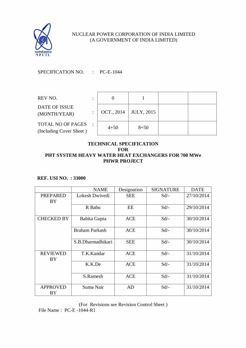
SPECIFICATION NO. : PC-E-1044
REV NO. : 0 1
DATE OF ISSUE
(MONTH/YEAR) : OCT., 2014 JULY, 2015
TOTAL NO OF PAGES
(Including Cover Sheet )
: 4+50 8+50
TECHNICAL SPECIFICATION
FOR
PHT SYSTEM HEAVY WATER HEAT EXCHANGERS FOR 700 MWe
PHWR PROJECT
REF. USI NO. : 33000
NAME Designation SIGNATURE DATE
PREPARED
BY
Lokesh Dwivedi SEE Sd/- 27/10/2014
R Babu EE Sd/- 29/10/2014
CHECKED BY
Babita Gupta
ACE Sd/- 30/10/2014
Braham Parkash
ACE Sd/- 30/10/2014
S.B.Dharmadhikari
SEE Sd/- 30/10/2014
REVIEWED
BY
T.K.Kandar ACE Sd/- 31/10/2014
K.K.De ACE Sd/- 31/10/2014
S.Ramesh ACE Sd/- 31/10/2014
APPROVED
BY
Suma Nair AD Sd/- 31/10/2014
(For Revisions see Revision Control Sheet )
File Name : PC-E -1044-R1

This page is intentionally left blank

This page has been kept intentionally blank

NPCIL PROPRIETARY
This document contains confidential and protected information and that the
same are the intellectual property of Nuclear Power Corporation of India
Limited (NPCIL). No part of this document including notably any editorial
element, verbal and figurative marks and images including herein, shall be
reproduced or transmitted or utilized or published or stored in any form or by
any means now known or hereinafter invented, electronic, digital or
mechanical, including photocopying, scanning, recording or by any
information storage or retrieval system, without prior written permission
from NPCIL, by any person or entity. Unauthorized use, disclosure or
copying is strictly prohibited and may constitute unlawful act and can attract
legal action.

This page has been kept intentionally blank
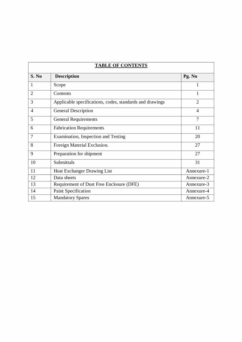
TABLE OF CONTENTS
S. No Description Pg. No
1 Scope 1
2 Contents 1
3 Applicable specifications, codes, standards and drawings 2
4 General Description 4
5 General Requirements 7
6 Fabrication Requirements 11
7 Examination, Inspection and Testing 20
8 Foreign Material Exclusion. 27
9 Preparation for shipment 27
10 Submittals 31
11 Heat Exchanger Drawing List Annexure-1
12 Data sheets Annexure-2
13 Requirement of Dust Free Enclosure (DFE) Annexure-3
14 Paint Specification Annexure-4
15 Mandatory Spares Annexure-5

This page has been kept intentionally blank
NUCLEAR POWER CORPORATION OF INDIA LTD ATOMIC POWER PROJECT
TECHNICAL SPECIFICATION
FOR
PHT SYSTEM HEAVY WATER HEAT
EXCHANGERS FOR 700 MWe PROJECTS
Page No. : 1 of 50
Rev.
No. : 1
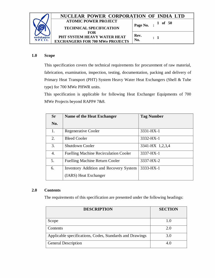
1.0 Scope
This specification covers the technical requirements for procurement of raw material,
fabrication, examination, inspection, testing, documentation, packing and delivery of
Primary Heat Transport (PHT) System Heavy Water Heat Exchangers (Shell & Tube
type) for 700 MWe PHWR units.
This specification is applicable for following Heat Exchanger Equipments of 700
MWe Projects beyond RAPP# 7&8.
Sr
No.
Name of the Heat Exchanger Tag Number
1. Regenerative Cooler 3331-HX-1
2. Bleed Cooler 3332-HX-1
3. Shutdown Cooler 3341-HX 1,2,3,4
4. Fuelling Machine Recirculation Cooler 3337-HX-1
5. Fuelling Machine Return Cooler 3337-HX-2
6. Inventory Addition and Recovery System
(IARS) Heat Exchanger
3333-HX-1
2.0 Contents
The requirements of this specification are presented under the following headings:
DESCRIPTION SECTION
Scope 1.0
Contents 2.0
Applicable specifications, Codes, Standards and Drawings 3.0
General Description 4.0
NUCLEAR POWER CORPORATION OF INDIA LTD ATOMIC POWER PROJECT
TECHNICAL SPECIFICATION
FOR
PHT SYSTEM HEAVY WATER HEAT
EXCHANGERS FOR 700 MWe PROJECTS
Page No. : 2 of 50
Rev.
No. : 1
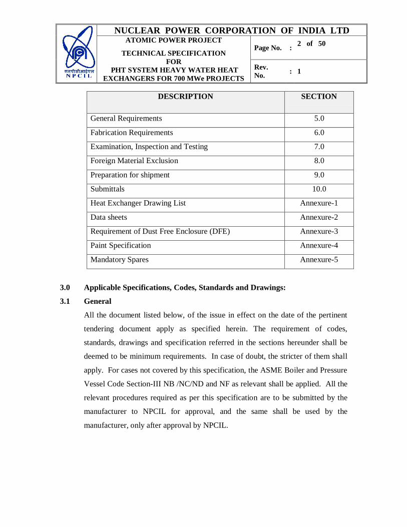
DESCRIPTION SECTION
General Requirements 5.0
Fabrication Requirements 6.0
Examination, Inspection and Testing 7.0
Foreign Material Exclusion 8.0
Preparation for shipment 9.0
Submittals 10.0
Heat Exchanger Drawing List Annexure-1
Data sheets Annexure-2
Requirement of Dust Free Enclosure (DFE) Annexure-3
Paint Specification Annexure-4
Mandatory Spares Annexure-5
3.0 Applicable Specifications, Codes, Standards and Drawings:
3.1 General
All the document listed below, of the issue in effect on the date of the pertinent
tendering document apply as specified herein. The requirement of codes,
standards, drawings and specification referred in the sections hereunder shall be
deemed to be minimum requirements. In case of doubt, the stricter of them shall
apply. For cases not covered by this specification, the ASME Boiler and Pressure
Vessel Code Section-III NB /NC/ND and NF as relevant shall be applied. All the
relevant procedures required as per this specification are to be submitted by the
manufacturer to NPCIL for approval, and the same shall be used by the
manufacturer, only after approval by NPCIL.
NUCLEAR POWER CORPORATION OF INDIA LTD ATOMIC POWER PROJECT
TECHNICAL SPECIFICATION
FOR
PHT SYSTEM HEAVY WATER HEAT
EXCHANGERS FOR 700 MWe PROJECTS
Page No. : 3 of 50
Rev.
No. : 1
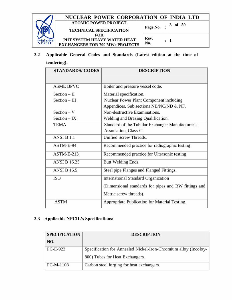
3.2 Applicable General Codes and Standards (Latest edition at the time of
tendering):
STANDARDS/ CODES DESCRIPTION
ASME BPVC
Section – II
Section – III
Section – V
Section – IX
Boiler and pressure vessel code.
Material specification.
Nuclear Power Plant Component including
Appendices, Sub sections NB/NC/ND & NF.
Non-destructive Examinations.
Welding and Brazing Qualification.
TEMA Standard of the Tubular Exchanger Manufacturer’s
Association, Class-C.
ANSI B 1.1 Unified Screw Threads.
ASTM-E-94 Recommended practice for radiographic testing
ASTM-E-213 Recommended practice for Ultrasonic testing
ANSI B 16.25 Butt Welding Ends.
ANSI B 16.5 Steel pipe Flanges and Flanged Fittings.
ISO International Standard Organization
(Dimensional standards for pipes and BW fittings and
Metric screw threads).
ASTM Appropriate Publication for Material Testing.
3.3 Applicable NPCIL’s Specifications:
SPECIFICATION
NO.
DESCRIPTION
PC-E-923 Specification for Annealed Nickel-Iron-Chromium alloy (Incoloy-
800) Tubes for Heat Exchangers.
PC-M-1108 Carbon steel forging for heat exchangers.
NUCLEAR POWER CORPORATION OF INDIA LTD ATOMIC POWER PROJECT
TECHNICAL SPECIFICATION
FOR
PHT SYSTEM HEAVY WATER HEAT
EXCHANGERS FOR 700 MWe PROJECTS
Page No. : 4 of 50
Rev.
No. : 1
SPECIFICATION
NO.
DESCRIPTION
PC-M-288 Carbon Steel Seamless Pipe Fittings and Piping Components for
primary system. (To be only used in case the equipment is Class-1
NB component, elsewhere applicable ASME codes will apply).
PC-M-1109 Inconel Welding Consumables and Overlay Cladding for PHT
system Heat Exchangers.
PC-P-192 Procedure for Tube sheet and Baffle Drilling of Heavy Water Heat
Exchanger.
PC-P-193 Procedure for Tube to Tube sheet Welding of Heavy Water Heat
Exchanger.
PC-P-194 Procedure for Tube Expansion.
PC-P-255 Procedure for Hydrostatic Test of Heavy Water heat Exchanger.
PC-P-257 Quality Assurance Plan for Heavy Water Heat Exchanger.
PC-P-258 Procedure for Ball Passage Test of Heavy Water Heat exchanger.
PP-P-1962 Procedure for Eddy current testing of Heat Exchangers
PP-E-2384 Specification for Helium leak testing in vacuum mode
3.4 Drawings
Applicable Drawings related to individual Heat exchanger equipments are listed
separately in Annexure-1
4.0 General Description
Regenerative Cooler (3331-HX-1)
Regenerative Cooler is a shell and tube Heavy water to Heavy water heat exchanger,
located in pump room at 115.5 M Fl. El. Hot bleed from Bleed Condenser is cooled by
feed flow (tube side) from the Primary Pressurizing Pumps, thus heating up the feed
NUCLEAR POWER CORPORATION OF INDIA LTD ATOMIC POWER PROJECT
TECHNICAL SPECIFICATION
FOR
PHT SYSTEM HEAVY WATER HEAT
EXCHANGERS FOR 700 MWe PROJECTS
Page No. : 5 of 50
Rev.
No. : 1
going to PHT main circuit. This scheme enables to recover system heat which
otherwise would have been lost in bleed cooler and also minimizes thermal stresses at
feed line - main circuit junction. Physically Regenerative Cooler is divided into two shells
and both heat exchangers are in series on tube side as well as shell side. The design
parameters and operating conditions are given in Regenerative Cooler data sheet attached
in Annexure-2.
Bleed Cooler (3332-HX-1)
Bleed Cooler is designed to cool bleed from Bleed Condenser outlet condition to near
ambient temperature. Bleed Cooler is also a shell and tube heat exchanger, located in
pump room at 115.5 M Fl. El. Hot bleed (Tube side) is cooled by Active Process Water
system (shell side). Physically Bleed Cooler is split into two heat exchangers which
are in series on tube side (Heavy Water side) and are also in series on shell side
(Active Process Water side). The design parameters and operating conditions are given in
Bleed Cooler data sheet attached in Annexure-2.
Shutdown Cooler (S/D) (3341-HX 1, 2, 3, 4)
The Shutdown Cooler is provided in the shutdown cooling system to cool the PHT heavy
water to below 150ºC and hold it cold enough for carrying out maintenance work. The
designed heat removal rate is in parity with the decay heat generation and hence ensures
that the specific design limits of the fuel are not exceeded during shutdown. Each PHT
loop has 2 x 100% S/D cooling pumps and 2 x 100% S/D cooling heat exchangers. S/D
cooling heat exchangers are located at 109 m of Reactor Building. The design parameters
and operating conditions are given in Shutdown Cooler data sheet attached in
Annexure-2.
NUCLEAR POWER CORPORATION OF INDIA LTD ATOMIC POWER PROJECT
TECHNICAL SPECIFICATION
FOR
PHT SYSTEM HEAVY WATER HEAT
EXCHANGERS FOR 700 MWe PROJECTS
Page No. : 6 of 50
Rev.
No. : 1
Fuelling Machine (F/M) Recirculation Cooler (3337-HX-1)
This heat exchanger is provided to cool the bypassed Heavy Water from F/M valve
station. The design parameters and operating conditions are given in F/M Recirculation
Cooler data sheet attached in Annexure-2.
Fuelling Machine (F/M) Return Cooler (3337-HX-2)
F/M Return Cooler cools down hot Fuelling Machine return flow to near ambient
temperature, before it is returned to storage tank/pump suction via purification. The
design parameters and operating conditions are given in F/M Return Cooler data sheet
attached in Annexure-2.
Inventory Addition & Recovery System (IARS) Heat Exchanger (3333-HX-1)
The IARS heat exchanger is provided to cool the spilled inventory collected in IARS tank
before pumping to D2O Storage tank 3333-TK-1 via purification circuit. The design
parameters and operating conditions are given in IARS Heat Exchanger data sheet
attached in Annexure-2.
4.1 Design Conditions
The design conditions and operating parameters of these Heat exchangers are given in
Annexure-2.
4.2 All these Heat Exchangers are designed in accordance with ASME Section- III
NB/NC/ND & NF (as applicable), TEMA Class-C for tube side and shell side and Heat
Exchanger Data Sheets (Annexure-2).
4.3 Seismic design criteria
The heat exchangers are designed for Safe Shutdown Earthquake (SSE) and Operating
Basis Earthquake (OBE) level earthquake as enumerated in respective Heat Exchanger
data sheets (Annexure-2).
NUCLEAR POWER CORPORATION OF INDIA LTD ATOMIC POWER PROJECT
TECHNICAL SPECIFICATION
FOR
PHT SYSTEM HEAVY WATER HEAT
EXCHANGERS FOR 700 MWe PROJECTS
Page No. : 7 of 50
Rev.
No. : 1
4.4 Nozzles and Supports
The loads and moments on the Heat exchanger nozzles and its supports due to piping
reactions from dead weight, thermal and seismic considerations are considered in the
design of the respective heat exchanger supporting structure
5.0 General Requirements
5.1 The Heat Exchanger’s shall be fabricated, inspected and tested to meet the requirements
of the ASME Boiler and Pressure Vessel Code, Section III, Nuclear Power Plant
Component under which parts of heat exchanger containing heavy water are classified as
Class-I/Class-II/Class-III components (as specified in relevant Heat Exchanger Data
Sheet Ref Annexure-2) and those parts containing Water are Class-III components.
However, the hub integral with the tube sheet shell side face shall be treated as Class-I if
the same is specified for tube side (Regenerative Cooler, Bleed Cooler and Shutdown
Cooler). The heat exchanger shall further meet the requirements of the standards of the
Tubular Exchanger Manufacturer’s Association (TEMA) Class-C. All the requirements
for heat exchangers, stated in individual data sheet, fabrication drawings approved by the
NPCIL and NPCIL’s tendering drawings shall be fully complied with. Material and
standard parts which are not specifically designated herein and which are necessary for
the fulfillment of this specification shall be of good quality and in accordance with the
best practice pertinent to the manufacture of heat exchanger.
In compliance with or supplementary to the ASME code, certain procedure shall be
qualified and the product shall meet the requirements stated herein. The inspection and
testing, whether required by the ASME code or specified herein shall be performed as
specified and the product shall meet the requirements stated herein.
5.2 Manufacturer shall be responsible for the preparation of shop fabrication drawings,
preparation and qualification of all procedures for fabrication/examination/ testing, data
accumulation/evaluation and reporting, procurement of raw material, performing all
NUCLEAR POWER CORPORATION OF INDIA LTD ATOMIC POWER PROJECT
TECHNICAL SPECIFICATION
FOR
PHT SYSTEM HEAVY WATER HEAT
EXCHANGERS FOR 700 MWe PROJECTS
Page No. : 8 of 50
Rev.
No. : 1
examinations and testing, final documentation, cleaning, drying and preparation for
shipment, shipment and full compliance with this specification.
5.3 The manufacturer shall accept full responsibility for his work and for the compliance
with this specification. Approval of drawings and documents by the NPCIL does not
constitute acceptance of any designs, materials or equipment, which will not fulfill the
requirements established by the purchase contract.
5.3.1 Sub-contractors:
In the event of the Manufacturer, sub-contracting part of the Heat Exchanger
component, the sub-contractor shall be approved by NPCIL before award of the work or
placement of the Purchase order. The subcontractor will be evaluated first by the
supplier and relevant reports should be submitted along with the proposal to NPCIL.
The sub-contractor shall not further sub-contract any part of work given to them.
Relevant technical specifications required by the subcontractor shall be handed over
only after obtaining written permission from NPCIL. The manufacturer shall be
responsible for ensuring that the sub-contractor makes the components as per relevant
codes, standards and specifications as enunciated in this specification by NPCIL. The
manufacturer shall be responsible for preparing uniform plans, lists and other documents
and for documentation by sub- contractor as per this specification.
All manufacturing documents prepared by the sub-contractors should be reviewed and
accepted/approved by the main contractor and the same shall be submitted to NPCIL
before the start of manufacture for review and approval.
5.4 Material
5.4.1 All raw materials shall be procured by the manufacturer. The material shall be
purchased with valid original test certificates. In absence of co-relating Mill certificates,
samples shall be drawn as per relevant specification in presence of NPCIL and check
test shall be carried out. Testing shall be done in NPCIL approved labs. The material test
certificates/reports will be further reviewed and accepted by NPCIL before use.
NUCLEAR POWER CORPORATION OF INDIA LTD ATOMIC POWER PROJECT
TECHNICAL SPECIFICATION
FOR
PHT SYSTEM HEAVY WATER HEAT
EXCHANGERS FOR 700 MWe PROJECTS
Page No. : 9 of 50
Rev.
No. : 1
All welding consumables for fabrication are to be procured by the manufacturer. The
welding consumables shall be procured from NPCIL’s approved vendors and shall be of
approved brand name.
5.4.2 The materials should be as per the tender drawings and should meet the corresponding
raw material specification. The Cobalt content shall be limited to 0.03% for SS material
and 0.02% for those CS material which are coming in contact with Heavy Water (D2O)
5.4.3 All SS material shall be Solution Annealed and Inter Granular Corrosion (IGC) tested as
per relevant material specification.
5.4.4 Materials, which are not specified herein or in drawings, shall be selected by
manufacturer in accordance with ASME B&PV code, Section-III NB/NC/ND (as
applicable) & Section-II with the approval of the NPCIL.
5.4.5 Any components/materials (tubes/shell/channel head/ tubesheet/nozzle) imported for use
in Heat Exchanger equipment shall have valid test certificate and compliance (to
specification) certificate duly certified by NPCIL approved inspection agency. Any
other imported raw material (to be used in Heat Exchanger) shall be duly tested in India
at NPCIL approved labs for certificate verification.
5.5 Nozzle End Connections
All connections to the heat exchanger vessel shall be in accordance with the requirement
of this specification and relevant drawings.
All connections shall terminate with end preparations for butt welding in accordance
with drawing no. NPCIL/01006/2232/SK (butt welding with “Y” type consumable
inserts) preferably.
In general, the following nozzle end connections, if not specified in the drawings, shall
be 150 mm long and free end shall be prepared for butt-welding to 20 mm NB x 4 mm
wall thickness pipe.
a) Vent and drain connections at the highest and lowest points respectively on shell
side.
NUCLEAR POWER CORPORATION OF INDIA LTD ATOMIC POWER PROJECT
TECHNICAL SPECIFICATION
FOR
PHT SYSTEM HEAVY WATER HEAT
EXCHANGERS FOR 700 MWe PROJECTS
Page No. : 10 of 50
Rev.
No. : 1
b) Vent and drain connections at the highest and lowest points respectively on tube
side each located in the channel cover.
c) Leak off connections for the space between the double gaskets, between channel
cover and tube sheet and any other double gasketted joint as applicable.
5.6 Threaded Fasteners
All threads shall conform to ISO ( Dimensional standard for metric threads ) or ANSI- B
1.1. All threaded fasteners shall be provided with corrosion resistant locking device. No
Frictional-locking device shall be used. Positive (non-friction) locking devices such as
castellated nuts with pins shall be provided on the bolts for channel cover – tube sheet
gasketted joints as given in respective heat exchanger drawings.
Bolting up of pressure boundary gasketted joints shall be done preferably by means of a
hydraulic tensioner. This is because of the uncertainty in estimating the actual bolt
tension values achieved by the conventional coefficients. Otherwise, if torquing is
adopted due to non-availability of hydraulic tensioner, suitable graphite based lubricant
shall be applied on the rubbing and bearing surfaces of the nut, bolt and flange surfaces.
In both cases, bolting up procedure of the gasketted joints shall be approved by NPCIL.
However, these requirements are not applicable to temporary nuts/bolts and gasket
arrangement used during post weld heat treatment of the vessel.
The bolts for spiral wound gasketted joints shall have unthreaded reduced shanks for
resilience. Suitable arrangement for mounting bolt elongation monitoring/measurement
device (while bolts are being tensioned) shall be indicated by the manufacturer. The
bolting up procedure shall include progressive step-wise application of bolt load and
measurement of corresponding bolt extensions, gasket compression and mating flange
deflections. All material required for fasteners shall be tested as per applicable
specification/ drawings/ approved material sampling and testing plans.
NUCLEAR POWER CORPORATION OF INDIA LTD ATOMIC POWER PROJECT
TECHNICAL SPECIFICATION
FOR
PHT SYSTEM HEAVY WATER HEAT
EXCHANGERS FOR 700 MWe PROJECTS
Page No. : 11 of 50
Rev.
No. : 1
6.0 Fabrication Requirements
6.1 Workmanship
Workmanship shall be in accordance with the best practice and adequate to ensure
satisfactory operation, ease of maintenance and service life of at least 40 years in
accordance with the provision of this specification.
6.2 Procedure
The manufacturer, before taking up the fabrication, shall submit all documents and
drawings as specified in section no. 10 for NPCIL’s approval. Results of exploratory
trials and tests to establish procedures are desirable evidence may be also submitted to
the NPCIL for information.
6.3 Heat Treatment
Heat-treatment shall be carried out in duly calibrated furnace only and evidence of
temperature distribution in the furnace is to be supplied to NPCIL for the furnaces
employed. Furnace shall be electrical/gas fired.
Heat Treatment Plan
The tube sheet after cladding and other components when required shall be heat
treated for stress relieving. For all heat treatment intended to be performed on
component or heat exchanger, heat treatment plan shall be established. The detailed
procedure shall be submitted to NPCIL for approval, prior to start of process.
6.4 Material Cutting
Carbon steel material may be cut to size and shape by flame cutting provided all
accumulation of slag oxides is removed from the cut surface. All flame cut edges shall
be machined or ground back to a minimum 3 mm past the deepest indentation.
NUCLEAR POWER CORPORATION OF INDIA LTD ATOMIC POWER PROJECT
TECHNICAL SPECIFICATION
FOR
PHT SYSTEM HEAVY WATER HEAT
EXCHANGERS FOR 700 MWe PROJECTS
Page No. : 12 of 50
Rev.
No. : 1
The local preheat for cutting may be used if required. The preheat temperature for
cutting shall be same as that for welding.
6.5 Tolerances and Surface Finish
The manufacturer shall be responsible for compliance with prescribed final
dimensions and tolerances. The dimensions for wall thickness of base material
given in the drawings are the minimum prescribed values and manufacturer
shall procure with positive tolerance only.
All welds and surfaces to be examined must be finished in such a way that a precise
coupling of such units is ensured during Ultrasonic examination. The requirements of
the corresponding specifications shall apply in such cases. All welds shall be ground
smooth. If the weld edges are dislocated either on the inside or outside within the
manufacturing tolerances, the transition shall be brought upto an angle of maximum 5º
and shall have a radius of minimum 250 mm. Written approval of NPCIL should be
taken for such welds, which shall be properly recorded.
6.6 Cleanliness
Tube sheets and baffles shall be maintained in a clean condition. Scrupulous attention
to cleanliness is essential for the satisfactory tube-to-tube sheet welds. Just before
closing of the channel side by assembling the cover, each tube shall be cleaned and
purged with clean oil free compressed air. Prior to carrying out eddy current
examination of tubes by ID probes to establish base line data for reference for future
health assessment as part of In Service Inspection (ISI), the manufacturer shall clean
each of the tubes by acetone soaked felt plugs driven by clean oil free compressed air.
All internal surfaces of the Heat Exchanger shall be clean to the degree that wiping
with clean white cloth results in no significant coloration of the cloth. The Heat
Exchanger shall be examined visually at appropriate stages of fabrication to ensure
that cleanliness is maintained.
NUCLEAR POWER CORPORATION OF INDIA LTD ATOMIC POWER PROJECT
TECHNICAL SPECIFICATION
FOR
PHT SYSTEM HEAVY WATER HEAT
EXCHANGERS FOR 700 MWe PROJECTS
Page No. : 13 of 50
Rev.
No. : 1
All stainless steel surfaces and outer edges shall be protected from contamination by
injurious and undesirable foreign matter at all stages of manufacture. Chemicals, oil,
grease and cleaning agents where used, shall be subject to NPCIL approval.
Chemical cleaning procedure shall be approved by NPCIL prior to start of cleaning
operations. Only certified and approved cleaning agents shall be employed. After
cleaning, the surface shall be free of chlorides and other injurious contaminants such
as Iron, Lead, Sulphur. Water with halogen content not exceeding 25 ppm shall be
used for flushing. All pickled surfaces shall be passivated as per NPCIL approved
procedures.
6.7 Forming and Bending Process
Any process may be used for forming or bending (hot /cold) of any pressure retaining
materials for component, provided the required tensile and impact properties are not
reduced below the minimum required values (as per material specification) or they are
effectively restored by heat treatment following the forming/bending operation.
Qualification of Forming and Bending Process
When required, procedure qualification test shall be conducted on specimens taken
from coupons of the same material specification as employed for the portion of the
component involved. The applicable tests shall be conducted (on coupons) to
determine that the required tensile and impact properties are met. The procedure is to
be submitted to NPCIL for approval prior to carrying out the qualification. If the
manufacturer has already conducted tests on similar materials, he shall submit the
relevant data to NPCIL for review and approval.
6.8 Welding
6.8.1 General
Welding operation shall be conducted under sheltered conditions. Welding work,
workshop facilities, the employment of welders and supervisory personnel must be
NUCLEAR POWER CORPORATION OF INDIA LTD ATOMIC POWER PROJECT
TECHNICAL SPECIFICATION
FOR
PHT SYSTEM HEAVY WATER HEAT
EXCHANGERS FOR 700 MWe PROJECTS
Page No. : 14 of 50
Rev.
No. : 1
available in accordance with the requirements of ASME. The general welding
qualification standard with above specification requirements shall be submitted for the
approval of NPCIL.
All welding shall be planned and conducted to minimize warping or undue distortion
of the assembled units. Machined surfaces and threads shall be protected against weld
splatters and restrained against warping.
Welding Equipments
A list of welding equipment to be used with model designation, control characteristics,
construction year and registration numbers and latest calibration certificate shall be
submitted to NPCIL. In addition to this, NPCIL shall be notified of the control
equipment and welding machines that are to be monitored and calibrated (random
parameter check shall be carried out by NPCIL).
Data of welding speed and wire feed rates (by recording or indicating instruments) are
required for automatic welding. Welding current and voltage must be documented on
continuous-recording devices. The agreement of NPCIL is required for exceptions to
these for cogent reasons. All welding equipment shall be maintained in a perfect
condition and checked regularly. Opportunities for verification shall be afforded to
NPCIL.
Requirements and functions of supervisory and welding personnel shall be clearly
defined. The supervisory personnel shall be responsible for the quality of the welding
work. The welding supervisory personnel shall not be engaged directly in welding.
6.8.2 Welding operation on the component shall only be commenced if:
a) Approved and released manufacturing plan and welding plan is available and
welds are covered by valid welding procedure qualification tests approved by
NPCIL.
b) The welding material (batch of electrodes, melts of wire/strip or flux batches and
combination thereof) have been released for welding by NPCIL (QA).
NUCLEAR POWER CORPORATION OF INDIA LTD ATOMIC POWER PROJECT
TECHNICAL SPECIFICATION
FOR
PHT SYSTEM HEAVY WATER HEAT
EXCHANGERS FOR 700 MWe PROJECTS
Page No. : 15 of 50
Rev.
No. : 1
6.8.3 Welding material shall meet relevant specification listed in part C of ASME Section II
except inconel consumables which are required to be procured as per NPCIL
specification (PC-M-1109).
6.8.4 Welding procedures used in the fabrication shall be qualified in accordance with
Section-III and Section-IX of ASME code. The welding procedure qualification test
shall be conducted in the presence of NPCIL (QA). The respective documents
(WPS/WIP) must be submitted to NPCIL for the approval of welding plan. The welds
shall be uniform throughout and shall blend smoothly into the parent metal. For each
welder, the appropriate approved welding procedure plan must be available.
During all welding operation, the welding parameters laid down in the welding
procedure specifications (WPS) shall be complied with and the same shall be ensured.
6.8.5 The copper nozzle (welding tip) of the welding equipment must be marked before use.
Upon completion of the work, the nozzle must be presented for checking. If a nozzle
melts into the weld during welding, the welding processes must be stopped
immediately, the occurrence noted down in the welding report and NPCIL be
informed. Only after being appraised by NPCIL and subsequent removal and
examination of the weld affected location, welding process may be continued using a
new nozzle.
6.8.6 Carbon electrodes without copper coating are only permissible for back gouging.
6.8.7 Welding Plan
A welding plan shall be established for each weld joint and repair. Tack welds shall
be included in the plan. In particular the welding procedure qualification must also be
listed. The welding plan requires the approval of NPCIL before the start of welding.
6.8.8 For all welding parameters (including preheat, weld inter-pass and post-heat treatment
temperatures) the allowable tolerance range established in the welding procedure
qualification test shall be specified. Following definition apply to pre-heat weld inter-
pass and post-heat treatment temperature.
NUCLEAR POWER CORPORATION OF INDIA LTD ATOMIC POWER PROJECT
TECHNICAL SPECIFICATION
FOR
PHT SYSTEM HEAVY WATER HEAT
EXCHANGERS FOR 700 MWe PROJECTS
Page No. : 16 of 50
Rev.
No. : 1
Pre-Heat Temperature
Temperature of work piece in weld zone (100 to 300 mm on either side of weld) at the
start of welding.
Caution
Local preheating shall be avoided as it could produce permanent deformation in final
as welded condition.
Weld Inter-pass Temperature
Temperature of the work piece, measured (100 to 300 mm on either side of weld) in
front of the welding location at or directly adjacent to the groove face. It shall not be
lower than the lowest pre-heat temperature and not higher than the maximum weld
inter-pass temperature given in the welding plan.
Post Weld Heat Treatment Temperature
Temperature of the work piece in the welding region during soaking as indicated in
the welding and heat treatment plans.
6.8.9 Stainless steel welds shall be cleaned with stainless steel wool or stainless steel
brushes before adding the next bead and following the final bead to facilitate
inspection. The light oxide discoloration, which forms on the weld surface, need not
be removed.
6.8.10 Welds shall be cleaned of slag and flux between passes and following the final
deposit.
6.8.11 Root passes of the welds, not accessible from both sides shall be made preferably by
using welding insert and/or by inert gas tungsten arc (GTAW) process.
6.8.12 All welds, unless otherwise specified, shall be full penetration welds.
6.8.13 All surfaces to be joined shall be thoroughly cleaned to prevent weld contamination
and all weld preparations shall be machined smooth and PT tested.
6.8.14 All weld surfaces shall be ground smooth with maximum reinforcement of 1.5 mm
and shall be free from any crevices or undercuts.
NUCLEAR POWER CORPORATION OF INDIA LTD ATOMIC POWER PROJECT
TECHNICAL SPECIFICATION
FOR
PHT SYSTEM HEAVY WATER HEAT
EXCHANGERS FOR 700 MWe PROJECTS
Page No. : 17 of 50
Rev.
No. : 1
6.8.15 Any cracks, blow holes or other defects which appear on the surface of weld beads
shall be removed by machining, chipping, grinding or arc gouging. Austenitic weld
repairs, if arc gouged, shall be followed by grinding. Austenitic welds shall not be
peened. Ferritic welds may be peened with the approval of NPCIL.
6.8.16 Temporary welds on the base material of the heat exchanger shall be located where
possible on the edges and areas that will be trimmed off. Temporary attachment, must
be made of killed steel. Cutting off shall be done mechanically as far as possible. If
flame cutting gauging is performed, the cut off location must be sufficiently far away
from the surface of the work place to avoid the part being metallurgically heat
affected. Cut off location must be ground flush to the surface and subjected to PT and
hardness test (if needed in specific case).
6.8.17 Wide welds to overcome poor fit are not permissible. Poor fits shall be remedied by
suitable means such as re-grooving and shall be subject to approval by NPCIL. Except
for small cavities, the manufacturer shall not correct a plate edge deficiency unless
approved by NPCIL and NPCIL may require that welding to correct a plate edge
deficiency be subjected to radiographic or other approved methods of examination.
6.8.18 Use of backing ring except in case of closure joint between tube sheet and secondary
shell, will be permitted only if the ring is removed after welding and the weld root is
subjected to and passes liquid penetrant examination.
6.8.19 Chemical composition of backing ring shall conform to that of base metal. If
consumable inserts are used, their composition shall conform to that of the filler metal
used in welding the joint.
6.9 Tube sheet Cladding
The tube sheet shall be procured as per NPCIL specification PC-M-1108.
6.9.1 The Inconel overlay cladding on the production component shall be done using
qualified heat/lot/batch of welding consumables, in accordance with qualified overlay
NUCLEAR POWER CORPORATION OF INDIA LTD ATOMIC POWER PROJECT
TECHNICAL SPECIFICATION
FOR
PHT SYSTEM HEAVY WATER HEAT
EXCHANGERS FOR 700 MWe PROJECTS
Page No. : 18 of 50
Rev.
No. : 1
cladding procedure by qualified welders/welding operators as specified in the NPCIL
specification PC-M-1109.
6.9.2 The tubesheet after cladding shall be stress relieved as per the requirements of ASME
section III and at a temperature of 600 +/- 10
degree C. The soaking time will depend on
tube-sheet thickness and the same shall be approved by NPCIL.
6.9.3 The tube sheet prior to cladding and after cladding & stress relieving shall be
subjected to liquid penetrant examination and Ultrasonic examination.
6.10 Tube sheet and Baffle Drilling
Tube Sheet and Baffles shall be drilled in accordance with NPCIL specification no.
PC-P-192: “Procedure for Tube sheet and Baffle Drilling ". Before taking up
production drilling, procedure shall be qualified. The CNC controlled single
spindle/multiple spindle drilling machine used for this purpose shall be in a technically
perfect condition. A continuous checking of drilling parameters and measurement
shall be ensured. The details of the drilling machine shall be made available to
NPCIL, prior to taking up the work. The drilling work shall be carried out only by
trained and qualified personnel, who have prolonged experience on similar job. All
work shall be carried out under the supervision of responsible persons of the
manufacturer. In order to perform the work, clear written operating instructions
indicating all important details shall be made available to the operating personnel. By
means of conducting a trial on qualification test specimen, the manufacturer shall
prove that the job could be carried out successfully using his CNC machine. He shall
also establish optimum drilling parameters through the trial.
6.11 Tube Bundle Assembly
6.11.1 Tube bundle assembly shall be carried out in clean room/Dust Free Enclosure (DFE).
The requirement of Dust Free Enclosure (DFE) is attached as Annexure-3.
NUCLEAR POWER CORPORATION OF INDIA LTD ATOMIC POWER PROJECT
TECHNICAL SPECIFICATION
FOR
PHT SYSTEM HEAVY WATER HEAT
EXCHANGERS FOR 700 MWe PROJECTS
Page No. : 19 of 50
Rev.
No. : 1
6.11.2 The Tube bundle skeleton assembly shall be checked for dimensional compliance
before inserting the tubes. Tubes ready for insertion, shall be thoroughly cleaned all
over by suitable cleaning solvent.
6.11.3 Burrs, drilling particles, all traces of grease, oil, machining lubricant, marking crayons
or any other foreign matter or contamination shall be removed from both sides of
baffles, tube sheet and from the interior of each hole prior to insertion of tubes.
6.11.4 All handling of the tubes, tube sheet and baffles shall be done with clean gloves.
6.11.5 Each tube after insertion shall be checked visually to ensure that surface is free of
scratch marks.
6.11.6 Cleanliness of tube bundle assembly shall be maintained throughout the operation.
6.12 Tube end Rolling
The tube ends shall be given a light rolling (contact rolling) to close clearance between
tube-sheet hole and tube OD. The length of tube end rolling shall be up to 3 to 4 mm
inside the tube-sheet, from the tube-sheet channel side face.
Tube End Rolling shall be in accordance with NPCIL procedure no. PC-P-194
" Procedure for Tube Expansion ". However, before taking up production tube end
rolling, procedure qualification shall be carried out.
6.13 Tube-to-Tube sheet weld
6.13.1 The tube to tube sheet weld joint shall be recessed type as shown in the tender
drawings and Semi automatic welding machine shall be used.
6.13.2 The welding shall be carried out in accordance with the NPCIL procedure no. PC-P-
193: “Procedure for Welding of Tube to Tube Sheet Joints”. However, before taking
up Production Tube to Tube sheet Welding, procedure qualification and operator
qualification shall be qualified as per above mentioned NPCIL specification.
NUCLEAR POWER CORPORATION OF INDIA LTD ATOMIC POWER PROJECT
TECHNICAL SPECIFICATION
FOR
PHT SYSTEM HEAVY WATER HEAT
EXCHANGERS FOR 700 MWe PROJECTS
Page No. : 20 of 50
Rev.
No. : 1
6.14 Expansion of Tubes in Tube-sheet
After Helium leak testing of tube to tube-sheet welds, all the tubes shall be
protractively expanded in the tube sheet using mechanical expanders. The rolling shall
begin at a point inside the tube sheet 15mm from its tube side face and shall terminate
at 2+1/-0
mm from the shell side face of the tube sheet. The expansion length/number of
stages will be as per the approved drawings. The manufacturer shall submit the
tube/tubesheet expansion procedure for approval of NPCIL.
The percentage reduction in the tube wall thickness due to rolling shall be 3 to 6
percent of nominal tube wall thickness.
Tube expansion shall be carried out in accordance with the NPCIL specification no.
PC-P-194 : “Procedure for Tube Expansion ". Before taking up Production rolling,
procedure qualification shall be carried out in accordance with the above mentioned
specification. Production control of expansion of Tubes into Tube sheet shall also be
carried out as per the requirements stated in the above specification.
7.0 Examination, Inspection and Testing
7.1 General
The manufacturer shall be responsible for and shall provide for and perform all the
examination, inspection and testing specified herein. The Heat Exchanger shall be
carefully examined during manufacture and after completion to determine its
conformance with this specification with respect to material ,workmanship, finish,
marking and dimension. Manufacturer shall also assess conformance with other
requirements stated or reasonably implied and not covered by specific examinations
and tests. The examination, inspection and testing shall be conducted in a manner
satisfactory to and shall be subject to the approval of the NPCIL. The NPCIL or his
authorized agencies shall have access to the Manufacturer’s premises at all reasonable
times to the extent necessary to assess compliance with the provision of this
NUCLEAR POWER CORPORATION OF INDIA LTD ATOMIC POWER PROJECT
TECHNICAL SPECIFICATION
FOR
PHT SYSTEM HEAVY WATER HEAT
EXCHANGERS FOR 700 MWe PROJECTS
Page No. : 21 of 50
Rev.
No. : 1
specification. Examination, inspection and test reports shall be submitted by the
manufacturer to NPCIL periodically.
NPCIL shall have the right to conduct at his own expense any additional examination,
inspection or testing as deemed necessary. At the request of the NPCIL, the
Manufacturer shall re-examine, re-inspect or re-test any component of the equipment.
Defects so revealed which do not meet the requirements of this specification shall be
cause for rejection of the component, or alternatively for repair and subsequent re-
examination, re-inspection and re-test. If defects are revealed, all such re-
examination, re-inspection and re-testing both before and after repair shall be at the
expense of the Manufacturer. If no unacceptable defects are revealed, re-examination,
re-inspection and re-testing requested by the NPCIL shall be at NPCIL's expense.
7.1.1 Quality Assurance
The quality assurance plan (QAP) shall ensure the quality control of raw materials,
welding filler metals/auxiliary materials, fabrication process etc. Suggested QAP is
indicated in NPCIL specification No. PC-P-257. Manufacturer shall prepare detailed
QAP for NPCIL approval based on suggested QAP.
7.1.2 Examination and Inspection on Test Failure
In the event of failure of the equipment of any part thereof to meet examination,
inspection or test requirements specified herein, the Manufacturer shall notify NPCIL.
The Manufacturer shall obtain permission from NPCIL before carrying out repair or
subsequent use of such equipment or part thereof. If the repairs, including redesign,
are likely to affect the results of examination, inspection and tests or work previously
completed, appropriate re-examination, re-inspection and re-testing shall be
conducted.
7.2 Material Examination and Tests
All materials designated as in conformance with ASME Section-II standard shall be
tested as required by such standard and examined and tested as per the requirement of
NUCLEAR POWER CORPORATION OF INDIA LTD ATOMIC POWER PROJECT
TECHNICAL SPECIFICATION
FOR
PHT SYSTEM HEAVY WATER HEAT
EXCHANGERS FOR 700 MWe PROJECTS
Page No. : 22 of 50
Rev.
No. : 1
ASME Section-III NB/NC/ND or NF as applicable and any special additional
requirements of this specification. The material toughness properties, when required
by ASME Section-III NB/NC/ND or NF shall be such that the RTNDT shall not be
higher than -15 oC. The lowest service temperature value used for impact testing shall
not be higher than +18 oC at which the Charpy V-notch energy and / or lateral
expansion values specified in ASME Section-III are to be met. Proof in the form of
certified examination and test reports or mill certificates that the required
examinations and tests have been carried out at the source will be acceptable, but if
they are not available, these examination and tests shall be performed by the
Manufacturer. However acceptance of material certificates is subject to satisfaction of
NPCIL and if required NPCIL may ask for retesting of material to conform to the
specification requirements.
7.3 Non-destructive Examinations
7.3.1 Liquid Penetrant /Magnetic Particle Examination (PT/ MT)
Liquid Penetrant/Magnetic Particle examination shall be performed in accordance with
ASME Section -V and Section-III NB/NC/ND/NF as applicable. Additional
requirements are as follows:
7.3.1.1 Liquid Penetrant Examination (PT)
a) Penetrant, developers and cleaning agents, shall preferably halogen free.
Halogen content in the penetrant, developer and cleaners to be used on
stainless steel material and sulphur in the penetrant, developer and cleaners to
be used on the nickel based alloy shall not exceed 1% of the residue weight as
determined by Article-6 of ASME Section V and respective ASTM standards.
Only NPCIL approved penetrant and developer agent shall be used.
b) Application of penetrant and developer from Aerosol type spray cans is
preferred.
c) The temperature of area to be examined shall be between 16ºC and 52 ºC.
NUCLEAR POWER CORPORATION OF INDIA LTD ATOMIC POWER PROJECT
TECHNICAL SPECIFICATION
FOR
PHT SYSTEM HEAVY WATER HEAT
EXCHANGERS FOR 700 MWe PROJECTS
Page No. : 23 of 50
Rev.
No. : 1
d) All traces of penetrant and of developer shall be removed from the work
immediately after the completion of examination.
7.3.1.2 Magnetic Particle Examination (MT)
a) Surface shall be prepared for examination by removal of scale (not just loose
scale). Scale shall be removed by a method, which will not obscure defects (shot
peening shall not be used as it obscures defects).
b) The indicating material shall be removed on completion of examination.
c) Demagnetization is required to achieve residual magnetism to less than 20 gauss or
equivalent.
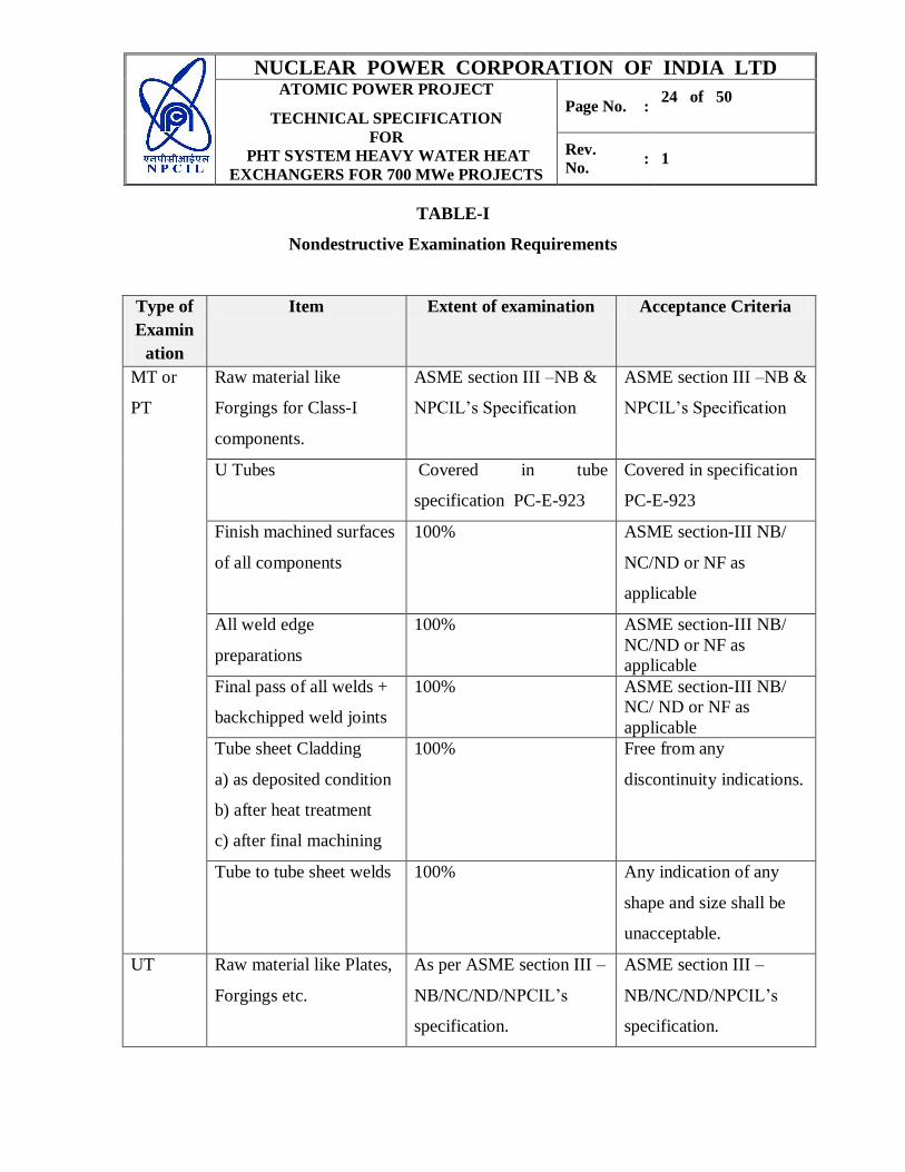
Table- I below describes the requirements of MT/PT examinations.
7.3.2 Ultrasonic Examination (UT)
7.3.2.1 Ultrasonic examination methods shall be in accordance with the requirements of
Section-III NB/NC/ND/NF (as applicable) and Section-V of the ASME code.
Table- I below describes the requirements of UT examination.
7.3.3 Radiography Examination (RT)
7.3.3.1 Radiography examination methods shall be in accordance with the requirements of
Section-III NB/NC/ND/NF (as applicable) and Section V of the ASME Code.
Radiographic technique shall be in accordance with ASTM E-94.
The quality level of the radiographic examination shall be 2-2T as defined in SE-94 of
section V of ASME code.
Table- I below describes the requirements of RT examinations.
NUCLEAR POWER CORPORATION OF INDIA LTD ATOMIC POWER PROJECT
TECHNICAL SPECIFICATION
FOR
PHT SYSTEM HEAVY WATER HEAT
EXCHANGERS FOR 700 MWe PROJECTS
Page No. : 24 of 50
Rev.
No. : 1
TABLE-I
Nondestructive Examination Requirements
Type of
Examin
ation
Item Extent of examination Acceptance Criteria
MT or
PT
Raw material like
Forgings for Class-I
components.
ASME section III –NB &
NPCIL’s Specification
ASME section III –NB &
NPCIL’s Specification
U Tubes Covered in tube
specification PC-E-923
Covered in specification
PC-E-923
Finish machined surfaces
of all components
100% ASME section-III NB/
NC/ND or NF as
applicable
All weld edge
preparations
100% ASME section-III NB/
NC/ND or NF as
applicable
Final pass of all welds +
backchipped weld joints
100% ASME section-III NB/
NC/ ND or NF as
applicable
Tube sheet Cladding
a) as deposited condition
b) after heat treatment
c) after final machining
100% Free from any
discontinuity indications.
Tube to tube sheet welds 100% Any indication of any
shape and size shall be
unacceptable.
UT Raw material like Plates,
Forgings etc.
As per ASME section III –
NB/NC/ND/NPCIL’s
specification.
ASME section III –
NB/NC/ND/NPCIL’s
specification.

NUCLEAR POWER CORPORATION OF INDIA LTD ATOMIC POWER PROJECT
TECHNICAL SPECIFICATION
FOR
PHT SYSTEM HEAVY WATER HEAT
EXCHANGERS FOR 700 MWe PROJECTS
Page No. : 25 of 50
Rev.
No. : 1
Type of
Examin
ation
Item Extent of examination Acceptance Criteria
Tube sheet cladding
before and after stress
reliving
NPCIL Specification No.
PC-M-1108
NPCIL Specification No.
PC-M-1108
Welds ASME section-III NB/
NC/ND or NF as
applicable
ASME section-III NB/
NC/ND or NF as
applicable
U Tubes Covered in tube
specification PC-E-923
Covered in specification
PC-E-923
RT All Pressure retaining
Welds (Wherever RT is
not feasible UT should
be carried out.)
100% ASME section III NB/
NC/ND or NF as
applicable
7.4.0 Helium Leak Testing
7.4.1 Helium leak testing shall be performed in vaccum mode as per NPCIL approved
procedure. Manufacturer shall refer specification no PP-E-2384 for preparation of
helium leak testing procedure. Leak detection shall be by means of any approved leak
detector set up to detect actual leakage rate of 1 x 10⁻⁷
Std. cc per second or better
from a single leak site on the job using appropriate technique.
7.4.2 Stages of Test and Test Coverage
a) During procedure qualification of tube-to-tube sheet weld, including repair
qualification.
b) The Helium leak test shall be conducted on every Heat Exchanger at the
following stages:
NUCLEAR POWER CORPORATION OF INDIA LTD ATOMIC POWER PROJECT
TECHNICAL SPECIFICATION
FOR
PHT SYSTEM HEAVY WATER HEAT
EXCHANGERS FOR 700 MWe PROJECTS
Page No. : 26 of 50
Rev.
No. : 1
i) After completion of tube-to-tube sheet welding, but prior to tube expansion
and rolling. This shall cover the tube-to-tube sheet welds and leak, if any, in
the tubes.
ii) Inter gasket space Helium leak test on tube side after tube and shell side
hydro test.
iii) Tube side Helium leak test after tube side hydro test and drying. This shall
cover the tube-to-tube sheet weld, tubes and welds in the pressure boundary
of channel side, channel cover to channel shell gasket joint and entire
channel side pressure boundary.
iv) Shell side Helium leak test to be done after shell side hydro test for only
those Heat Exchangers having D2O on shell side (Regenerative Cooler).
Note: The manufacturer shall submit detailed drying procedure to ensure proper
and meaningful helium leak test.
7.4.3 Acceptance
a) Leak rate shall not exceed 1x10⁻⁷
std. cc /sec. of helium from a single leak and
1x10⁻⁶
std. cc/sec. of helium for global.
b) For gasket joint: Leak rate shall not exceed 1x 10⁻⁴
std.cc/sec. of helium.
7.5 Hydrostatic Test
7.5.1 The shell and tube sides of the completed Heat Exchanger shall be hydrostatically
pressure tested as per NPCIL approved procedure. Manufacturer shall refer NPCIL
procedure specification No. PC-P-255 for preparation of Hydrotest procedure. The
metal temperature anywhere shall be well above RTNDT + 60 deg. F (33 deg. C)
during the entire test.
7.5.2 Acceptance
a) There shall not be any recordable change in test pressure during testing.
b) There should be no leakage and distortion.
NUCLEAR POWER CORPORATION OF INDIA LTD ATOMIC POWER PROJECT
TECHNICAL SPECIFICATION
FOR
PHT SYSTEM HEAVY WATER HEAT
EXCHANGERS FOR 700 MWe PROJECTS
Page No. : 27 of 50
Rev.
No. : 1
7.6 Ball Passage Test
Ball Passage Test shall be carried out after hydro test of tube side using Teflon balls
which are shot through the U tubes by compressed Nitrogen gas. The test ensures that
no foreign material /part is left inside the tubes or any blockage and detects collapse of
tubes if any. The test shall be carried out as per NPCIL approved procedure. NPCIL
procedure specification No. PC-P-258 shall be referred for preparation of Ball passage
test procedure.
After Ball passage test and before final closing of primary side all tubes shall be
thoroughly cleaned as per approved procedure.
7.7 Eddy Current Testing
Eddy current examination of tubes by ID probes shall be carried out at
manufacturer’s shop after completion of heat exchanger fabrication in order to
establish base line data for reference for future health assessment. The procedure
for eddy current testing shall be submitted for approval of NPCIL prior to
carrying out Eddy current testing. NPCIL procedure specification No. PP-P-1962
shall be referred for preparation of Eddy current test procedure
8.0 Foreign Material Exclusion (FME)
All fabrication / manufacturing activities shall be carried out in a manner to ensure that
no foreign material (eg. loose metal pieces, weld spatter, tools & tackles etc.) is left in
any part of the Heat Exchanger. The manufacturer shall have a comprehensive FME
programme, duly approved by the Purchaser, to ensure the same. Before final boxing
up of the heat exchanger for shipment, a thorough inspection of HX internals shall be
carried out to ensure that no foreign material is left inside.
NUCLEAR POWER CORPORATION OF INDIA LTD ATOMIC POWER PROJECT
TECHNICAL SPECIFICATION
FOR
PHT SYSTEM HEAVY WATER HEAT
EXCHANGERS FOR 700 MWe PROJECTS
Page No. : 28 of 50
Rev.
No. : 1
9.0 Preparation for Shipment
9.1 Identification
Identification tag numbers are indicated on the heat exchanger data sheets. The
Manufacturer shall engrave the tag number on a thin rectangular metal piece
(made of SS 304 or equivalent material) and the same shall be securely attached to
the heat exchanger unit. The engraving font shall be of sufficient size so as to be
easily readable.
9.2 Heat Exchanger
Packaging for shipment shall be in accordance with the instruction outlined below:
The vessel and its accessories, if any, shall be thoroughly cleaned and dried
before shipment. The shell side and tube side shall be cleaned from inside and
outside. Shell side of Heat Exchanger shall be thoroughly dried by passing hot
air/Nitrogen. The tube side of all Heat Exchangers and both tube & shell side of
the Regenerative Cooler shall be thoroughly dried by passing dry Nitrogen gas
with a dew point checking of -10 oC. Drying procedure shall be submitted for
approval of NPCIL prior to carrying out drying.
All finished or machined external carbon steel surfaces shall be protected against
corrosion with a liberal coating of an approved, easily removable compound. The
compound shall be such that it will remain on the surface at temperatures
normally encountered during shipment, storage and operation. All machined
surfaces shall be protected against mechanical damage.
All external unfinished carbon steel surface shall be shot blasted and coated with
Inorganic zinc silicate primer and Epoxy paint (minimum dry film thickness of
250 microns including primer thickness of 50-75 microns) of aircraft gray colour
or high temperature (326°C) application paint (minimum dry film thickness 100-
150 microns including primer) as applicable to specific Heat Exchangers. NPCIL

NUCLEAR POWER CORPORATION OF INDIA LTD ATOMIC POWER PROJECT
TECHNICAL SPECIFICATION
FOR
PHT SYSTEM HEAVY WATER HEAT
EXCHANGERS FOR 700 MWe PROJECTS
Page No. : 29 of 50
Rev.
No. : 1
certified paints and suppliers are listed in Annexure-4. The paint brand and
application procedure shall be subjected to approval of NPCIL.
The vessel shall be purged of air and filled with dry nitrogen on both the shell and tube
sides to well above atmospheric pressure (0.3 kg/cm2 (g)) and sealed properly prior to
shipment. Two pressure gauges (duly calibrated with valid certificates) at highest
points of the heat exchanger shall be installed to ensure that inert gas pressure during
shipment and storage is maintained well above atmospheric pressure. Gauges shall be
protected/ secured such as to avoid any damage during transportation. Certificate of
Pressure gauges shall be forwarded along with the equipment.
All openings shall be adequately sealed. Flanged openings, if any, shall be covered
with blank flanges held in place with at least four bolts and sealed with blank gaskets
of natural rubber or equivalent. Butt weld openings shall be closed with fillet welded
slip-on type temporary covers.
Internally threaded pipe connections shall be plugged with a threaded metal plug and
sealed with tape. No thread lubricant shall be used. Externally threaded pipe
connections shall be similarly protected with caps and thread-tape.
The orientation of the heat exchanger unit during transportation shall be such that the
tube bundle gets support from the internal structural guide-cum-support. Manufacturer
shall ensure that the tube bundles do not get damaged during transportation due to
vibrations or jerks etc.
All components shall be tropical packed, suitably boxed, crated and protected from
damage in transit to site. Equipment shall be prepared for a period in transit exceeding
two months. The construction and lining of the box shall provide protection for its
contents. The packaging shall also include adequate cushioning, blocking, bracing,
skidding, hoisting and tie-down provisions. The packaging and preparation for
shipment shall be subject to NPCIL’s approval.
NUCLEAR POWER CORPORATION OF INDIA LTD ATOMIC POWER PROJECT
TECHNICAL SPECIFICATION
FOR
PHT SYSTEM HEAVY WATER HEAT
EXCHANGERS FOR 700 MWe PROJECTS
Page No. : 30 of 50
Rev.
No. : 1
9.3 Small Parts
All small and loose pieces, including fasteners, tools, gaskets, etc. shall be adequately
crated or boxed for protection during shipment. Parts subject to rusting shall be
suitably protected. All pieces shall be marked with the equipment piece number or
mark number specified by NPCIL
9.4 Spares
The spares supplied by the manufacturer under the contract shall be of best quality and
workmanship. The list of mandatory spare to be supplied with the Heat Exchangers are
given in Annexure-5.
9.5 Shipping weight and Dimensions
Estimated shipping weights and overall clearance dimension shall be supplied to the
NPCIL at least two months in advance before shipping.
10.0 Submittals
All submittals to NPCIL such as drawings, fabrication procedures, material
specification, test reports and other documents shall be in four hard copies.
10.1 Fabrication
Following shall be submitted to the NPCIL for Approval:
a) All fabrication drawings (Minimum submission size A1 )
b) Quality Assurance Plan (QAP) for following :-
i) Complete fabrication of Heat exchanger
ii) Materials in the scope of manufacturer like tubes, forgings ( tubesheet, channel
head, shell, dished end , nozzles etc), flanges , fasteners etc.
c) Fabrication/Operation Process Sheet
d) Heat Treatment Plans.
NUCLEAR POWER CORPORATION OF INDIA LTD ATOMIC POWER PROJECT
TECHNICAL SPECIFICATION
FOR
PHT SYSTEM HEAVY WATER HEAT
EXCHANGERS FOR 700 MWe PROJECTS
Page No. : 31 of 50
Rev.
No. : 1
e) Tube sheet cladding, Welding and weld repair procedures.
f) Any other Repair procedures.
g) Technical purchase specification for the materials in the scope of manufacturer.
h) Tube sheet/Baffle drilling Procedure.
i) Tube to tube sheet welding procedure.
j) Contact rolling and Tube expansion procedure.
k) Tube Bundle preparation and tube insertion procedure.
l) Hydro test procedure.
m) Helium leak test Procedure.
n) Draining and Drying procedure.
o) Ball passage test procedure
p) All Non destructive examination procedures (PT/MT/RT/UT/ECT).
q) Cleaning and preserving procedures, with chemical composition of solution or
agents.
r) Surface Preparation and Painting.
s) Packing procedure.
Any deviation from this specification and tender drawings is to be submitted for
NPCIL approval.
10.2 History Document
10.2.1 General Requirements:
a) The history document shall be prepared for each Heat Exchanger separately.
b) Two copies (One original+ one copy) of the history documents duly approved by
NPCIL’s inspection agency shall be put in properly identified hard cover bound
volumes and shall be submitted to the NPCIL.
c) Four sets of history documents shall be prepared on computer compact discs
(DVD) with appropriate software for indexing and search and shall be submitted
to the NPCIL.
NUCLEAR POWER CORPORATION OF INDIA LTD ATOMIC POWER PROJECT
TECHNICAL SPECIFICATION
FOR
PHT SYSTEM HEAVY WATER HEAT
EXCHANGERS FOR 700 MWe PROJECTS
Page No. : 32 of 50
Rev.
No. : 1
10.2.2 Contents
The history document shall contain following documents/drawings/certificates in the
same order as written below:
a) An index for history document.
b) Purchase Order (Main PO and un-priced sub PO including amendments if any)
c) Copy of Tender specification including technical specifications of all items of
equipment and support structure.
d) Copy of shipping release bearing the signature and seal of NPCIL’s inspector or
NPCIL’s authorized inspection agency.
e) All design concession records and Non conformity reports.
f) List of As built drawings.
g) One copy each of the following approved documents:
i) Detailed Quality Assurance Plans along with inspection reports.
ii) Manufacturing sequence plan.
iii) Heat treatment plan (if applicable).
iv) Ultra-sonic Testing procedure.
v) Radiographic Testing procedure.
vi) Magnetic Particle testing/Dye penetrant testing procedure.
vii) Hydro test and Helium leak test procedures.
viii) Drying procedure.
ix) Eddy Current test procedure.
x) Ball passage test procedure.
xi) List of welding consumables used, with consumable manufacturers name and
brand.
xii) All welding procedure specification including repair records.
xiii) Cleaning, preservation and packaging procedures.
xiv) Any other procedure approved by NPCIL.
NUCLEAR POWER CORPORATION OF INDIA LTD ATOMIC POWER PROJECT
TECHNICAL SPECIFICATION
FOR
PHT SYSTEM HEAVY WATER HEAT
EXCHANGERS FOR 700 MWe PROJECTS
Page No. : 33 of 50
Rev.
No. : 1
h) Certificates of the following tests / examination, signed by NPCIL’s inspector or
NPCIL’s authorized inspection agency:
i) Hydro test
ii) Heat treatment, if any.
iii) Helium leak test.
iv) Ball passes test
v) All Mechanical tests.
vi) All Non Destructive examinations.
vii) Record of dimension/inspection reports.
viii) Pre service base line information report ( ECT ).
i) All raw material/consumable identification reports and test certificates counter signed
by NPCIL’s inspector or NPCIL’s authorized inspection agency.
j) The as built General arrangement, tube bundle, channel head, baffles, fasteners and
the supporting structure drawings will be given in PDF and Autocad.
k) Rub off of stamping on nameplate.
l) Manufacturer’s compliance certificate indicating completeness of the job and
guarantee period.
m) Certificate of completeness of the history document duly signed by NPCIL’s
inspector or NPCIL’s authorized inspection agency.
Note: The history document shall not only be regarded as an evidence of specified
tests and examinations but also an instrument for fulfillment of contract.
NUCLEAR POWER CORPORATION OF INDIA LTD ATOMIC POWER PROJECT
TECHNICAL SPECIFICATION
FOR
PHT SYSTEM HEAVY WATER HEAT
EXCHANGERS FOR 700 MWe PROJECTS
Page No. : 34 of 50
Rev.
No. : 1
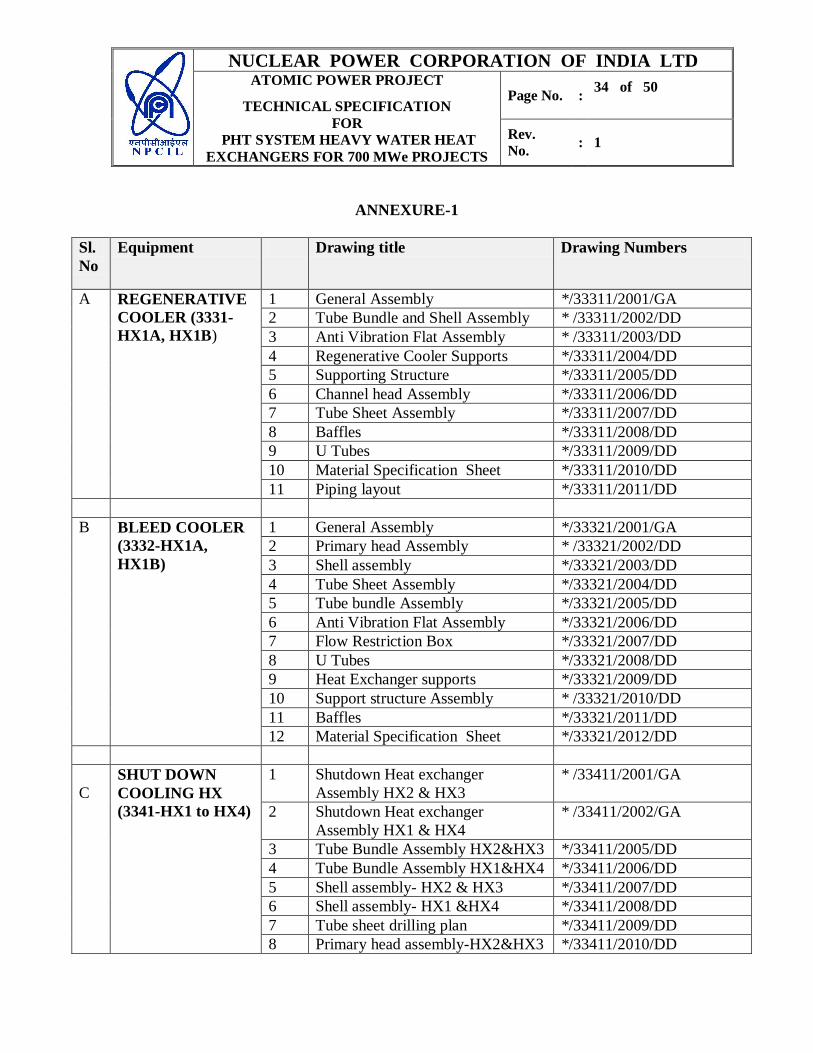
ANNEXURE-1
Sl.
No
Equipment Drawing title Drawing Numbers
A REGENERATIVE
COOLER (3331-
HX1A, HX1B)
1 General Assembly */33311/2001/GA
2 Tube Bundle and Shell Assembly * /33311/2002/DD
3 Anti Vibration Flat Assembly * /33311/2003/DD
4 Regenerative Cooler Supports */33311/2004/DD
5 Supporting Structure */33311/2005/DD
6 Channel head Assembly */33311/2006/DD
7 Tube Sheet Assembly */33311/2007/DD
8 Baffles */33311/2008/DD
9 U Tubes */33311/2009/DD
10 Material Specification Sheet */33311/2010/DD
11 Piping layout */33311/2011/DD
B BLEED COOLER
(3332-HX1A,
HX1B)
1 General Assembly */33321/2001/GA
2 Primary head Assembly * /33321/2002/DD
3 Shell assembly */33321/2003/DD
4 Tube Sheet Assembly */33321/2004/DD
5 Tube bundle Assembly */33321/2005/DD
6 Anti Vibration Flat Assembly */33321/2006/DD
7 Flow Restriction Box */33321/2007/DD
8 U Tubes */33321/2008/DD
9 Heat Exchanger supports */33321/2009/DD
10 Support structure Assembly * /33321/2010/DD
11 Baffles */33321/2011/DD
12 Material Specification Sheet */33321/2012/DD
C
SHUT DOWN
COOLING HX
(3341-HX1 to HX4)
1 Shutdown Heat exchanger
Assembly HX2 & HX3
* /33411/2001/GA
2 Shutdown Heat exchanger
Assembly HX1 & HX4
* /33411/2002/GA
3 Tube Bundle Assembly HX2&HX3 */33411/2005/DD
4 Tube Bundle Assembly HX1&HX4 */33411/2006/DD
5 Shell assembly- HX2 & HX3 */33411/2007/DD
6 Shell assembly- HX1 &HX4 */33411/2008/DD
7 Tube sheet drilling plan */33411/2009/DD
8 Primary head assembly-HX2&HX3 */33411/2010/DD
NUCLEAR POWER CORPORATION OF INDIA LTD ATOMIC POWER PROJECT
TECHNICAL SPECIFICATION
FOR
PHT SYSTEM HEAVY WATER HEAT
EXCHANGERS FOR 700 MWe PROJECTS
Page No. : 35 of 50
Rev.
No. : 1
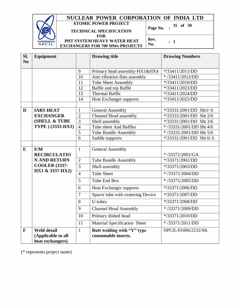
Sl.
No
Equipment Drawing title Drawing Numbers
9 Primary head assembly-HX1&HX4 */33411/2011/DD
10 Anti vibration flats assembly * /33411/2012/DD
11 Tube Sheet Assembly */33411/2019/DD
12 Baffle and top Baffle */33411/2023/DD
13 Thermal Baffle */33411/2024/DD
14 Heat Exchanger supports */33411/2025/DD
D IARS HEAT
EXCHANGER
(SHELL & TUBE
TYPE ) (3333-HX1)
1 General Assembly */33331/2001/DD Sht1/ 6
2 Channel Head assembly */33331/2001/DD Sht 2/6
3 Shell assembly */33331/2001/DD Sht 3/6
4 Tube sheet And Baffles * /33331/2001/DD Sht 4/6
5 Tube Bundle Assembly * /33331/2001/DD Sht 5/6
6 Saddle supports */33331/2001/DD Sht 6/ 6
E F/M
RECIRCULATIO
N AND RETURN
COOLER (3337-
HX1 & 3337-HX2)
1 General Assembly
* /33371/2001/GA
2 Tube Bundle Assembly */33371/2002/DD
3 Shell assembly */33371/2003/DD
4 Tube Sheet * /33371/2004/DD
5 Tube End Box * /33371/2005/DD
6 Heat Exchanger supports */33371/2006/DD
7 Spacer tube with centering Device */33371/2007/DD
8 U-tubes */33371/2008/DD
9 Channel Head Assembly * /33371/2009/DD
10 Primary dished head */33371/2010/DD
11 Material Specification Sheet * /33371/2011/DD
F Weld detail
(Applicable to all
heat exchangers)
1 Butt welding with “Y” type
consumable inserts.
NPCIL/01006/2232/SK
(* represents project name)

NUCLEAR POWER CORPORATION OF INDIA LTD ATOMIC POWER PROJECT
TECHNICAL SPECIFICATION
FOR
PHT SYSTEM HEAVY WATER HEAT
EXCHANGERS FOR 700 MWe PROJECTS
Page No. : 36 of 50
Rev.
No. : 1
ANNEXURE-2
DATA SHEETS
1) REGENERATIVE COOLER (RGCL)
Sr
No
Parameter Description
1. Equipment Regenerative Cooler (RGCL)
2. Quantity/unit 1
3. Tag No. 3331-HX-1A &1B (2 Shells in series each
with following details).
4. Equipment Location Pump Room Floor (FL.EL.115.5 M)
5. Design Conditions Tube Side Shell Side
Design Pressure
Design Temperature
150 kg/cm2(g)
3260C
126 kg/cm2(g)
3260C
6. Design Classification
ASME Section- III
Class-I (NB) Class-I (NB)
7. Seismic Classification &
structural integrity
SSE & OBE SSE & OBE
8. Service Conditions Tube Side Shell Side
Fluid Heavy Water Heavy Water
Flow Rate, lpm 1200.0 2000.0
Flow Rate, kg/hr 79647.0 107875.5
Inlet temperature, oC 40.0 240.0
Outlet temperature, oC 224.72 106.34
Heat Load, kcal/hr. 14.74 x 10⁶ (17.13 MWe)
No. of Passes 2 1
Pressure Drop, kg/cm2 0.284 4.46
The inlet and outlet temperatures specified are across the combined assembly of
two HX shells in series arrangement.
9. Shop Test
Testing Conditions Tube Side Shell Side
Air hold / leak test pressure 7.0 kg/cm2(g) 7.0 kg/cm
2(g)
Helium leak test Required Required
NUCLEAR POWER CORPORATION OF INDIA LTD ATOMIC POWER PROJECT
TECHNICAL SPECIFICATION
FOR
PHT SYSTEM HEAVY WATER HEAT
EXCHANGERS FOR 700 MWe PROJECTS
Page No. : 37 of 50
Rev.
No. : 1
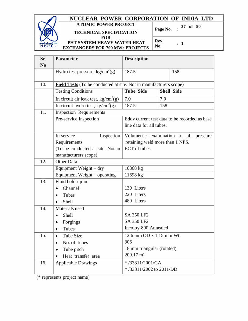
Sr
No
Parameter Description
Hydro test pressure, kg/cm2(g) 187.5 158
10. Field Tests (To be conducted at site. Not in manufacturers scope)
Testing Conditions Tube Side Shell Side
In circuit air leak test, kg/cm2(g) 7.0 7.0
In circuit hydro test, kg/cm2(g) 187.5 158
11. Inspection Requirements
Pre-service Inspection
Eddy current test data to be recorded as base
line data for all tubes.
In-service Inspection
Requirements
(To be conducted at site. Not in
manufacturers scope)
Volumetric examination of all pressure
retaining weld more than 1 NPS.
ECT of tubes.
12. Other Data
Equipment Weight – dry 10868 kg
Equipment Weight – operating 11698 kg
13. Fluid hold-up in
Channel
Tubes
Shell
130 Liters
220 Liters
480 Liters
14. Materials used
Shell
Forgings
Tubes
SA 350 LF2
SA 350 LF2
Incoloy-800 Annealed
15. Tube Size
No. of tubes
Tube pitch
Heat transfer area
12.6 mm OD x 1.15 mm Wt.
306
18 mm triangular (rotated)
209.17 m2
16. Applicable Drawings * /33311/2001/GA
* /33311/2002 to 2011/DD
(* represents project name)
NUCLEAR POWER CORPORATION OF INDIA LTD ATOMIC POWER PROJECT
TECHNICAL SPECIFICATION
FOR
PHT SYSTEM HEAVY WATER HEAT
EXCHANGERS FOR 700 MWe PROJECTS
Page No. : 38 of 50
Rev.
No. : 1
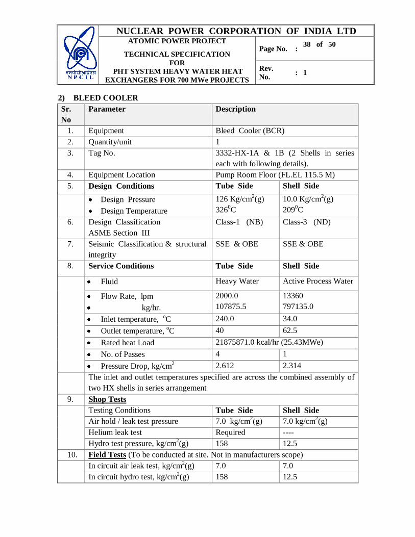
2) BLEED COOLER
Sr.
No
Parameter Description
1. Equipment Bleed Cooler (BCR)
2. Quantity/unit 1
3. Tag No. 3332-HX-1A & 1B (2 Shells in series
each with following details).
4. Equipment Location Pump Room Floor (FL.EL 115.5 M)
5. Design Conditions Tube Side Shell Side
Design Pressure
Design Temperature
126 Kg/cm2(g)
3260C
10.0 Kg/cm2(g)
2090C
6. Design Classification
ASME Section III
Class-1 (NB) Class-3 (ND)
7. Seismic Classification & structural
integrity
SSE & OBE SSE & OBE
8. Service Conditions Tube Side Shell Side
Fluid Heavy Water Active Process Water
Flow Rate, lpm
kg/hr.
2000.0
107875.5
13360
797135.0
Inlet temperature, oC 240.0 34.0
Outlet temperature, oC 40 62.5
Rated heat Load 21875871.0 kcal/hr (25.43MWe)
No. of Passes 4 1
Pressure Drop, kg/cm2 2.612 2.314
The inlet and outlet temperatures specified are across the combined assembly of
two HX shells in series arrangement
9. Shop Tests
Testing Conditions Tube Side Shell Side
Air hold / leak test pressure 7.0 kg/cm2(g) 7.0 kg/cm
2(g)
Helium leak test Required ----
Hydro test pressure, kg/cm2(g) 158 12.5
10. Field Tests (To be conducted at site. Not in manufacturers scope)
In circuit air leak test, kg/cm2(g) 7.0 7.0
In circuit hydro test, kg/cm2(g) 158 12.5
NUCLEAR POWER CORPORATION OF INDIA LTD ATOMIC POWER PROJECT
TECHNICAL SPECIFICATION
FOR
PHT SYSTEM HEAVY WATER HEAT
EXCHANGERS FOR 700 MWe PROJECTS
Page No. : 39 of 50
Rev.
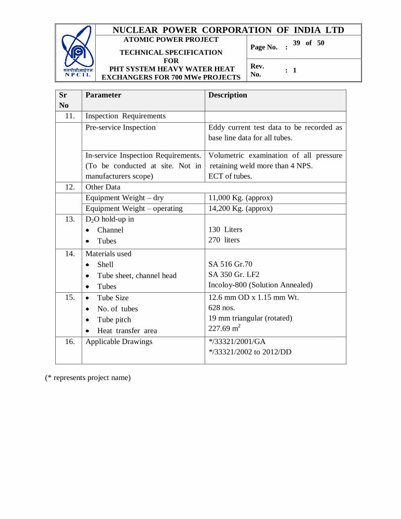
No. : 1
Sr
No
Parameter Description
11. Inspection Requirements
Pre-service Inspection
Eddy current test data to be recorded as
base line data for all tubes.
In-service Inspection Requirements.
(To be conducted at site. Not in
manufacturers scope)
Volumetric examination of all pressure
retaining weld more than 4 NPS.
ECT of tubes.
12. Other Data
Equipment Weight – dry 11,000 Kg. (approx)
Equipment Weight – operating 14,200 Kg. (approx)
13. D2O hold-up in
Channel
Tubes
130 Liters
270 liters
14. Materials used
Shell
Tube sheet, channel head
Tubes
SA 516 Gr.70
SA 350 Gr. LF2
Incoloy-800 (Solution Annealed)
15. Tube Size
No. of tubes
Tube pitch
Heat transfer area
12.6 mm OD x 1.15 mm Wt.
628 nos.
19 mm triangular (rotated)
227.69 m2
16. Applicable Drawings
*/33321/2001/GA
*/33321/2002 to 2012/DD
(* represents project name)

NUCLEAR POWER CORPORATION OF INDIA LTD ATOMIC POWER PROJECT
TECHNICAL SPECIFICATION
FOR
PHT SYSTEM HEAVY WATER HEAT
EXCHANGERS FOR 700 MWe PROJECTS
Page No. : 40 of 50
Rev.
No. : 1
3). SHUTDOWN COOLER
Sr.
No
Parameter Description
1. Equipment No. Shutdown Cooler
2. Tag No 3341-HX-1, HX-2, HX-3 & HX-4
3. Location 109.0 M EL. Floor Reactor Building
4. Quantity/unit 4
5. Design Condition. Tube Side Shell Side
Pressure 126 kg/cm2(g) 10.0 kg/cm
2(g)
Temperature 3260C 209
0C
6. Design Classification
ASME Section III
Class-1 (NB) Class-3 (ND)
7. Seismic Classification & Structural
Integrity
SSE & OBE SSE & OBE
8. Service Conditions Tube Side Shell Side
Fluid Heavy Water Active Process
Water
Flow Rate – m3/hr 700 775
Inlet temperature, oC 54 35
Outlet temperature, oC 47 42
Rated heat Load 5.133 x 10⁶ kcal/hr (5.97 MWe)
Pressure Drop, kg/cm2 0.8 1.5
Number of Passes 2 1
9. Shop Test
Tube Side Shell Side
Air hold / leak test pressure 7.0 kg/cm2(g) 7.0 kg/cm
2(g)
Hydro-static test pressure 157.5 kg/cm2(g) 12.5 kg/cm
2(g)
Helium leak test Required ---
10. Field Test (To be conducted at site. Not in manufacturers scope)
In-circuit air hold/leak 7 kg/cm2(g) 7 kg/cm
2(g)
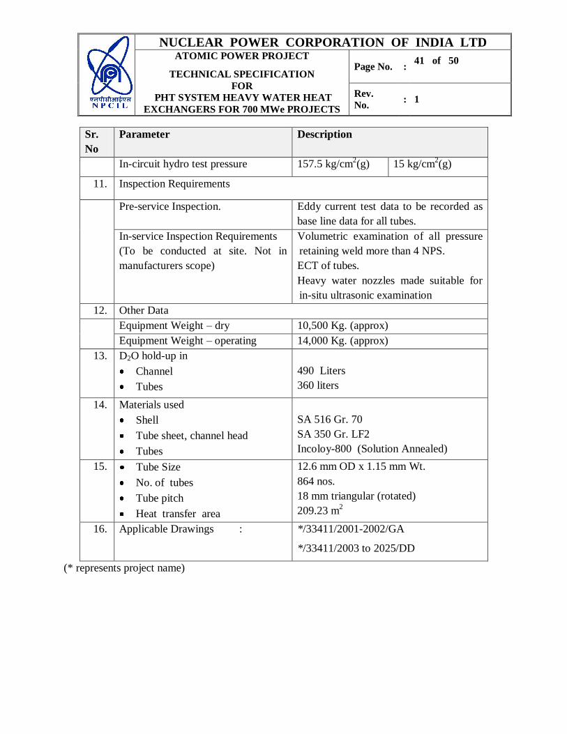
NUCLEAR POWER CORPORATION OF INDIA LTD ATOMIC POWER PROJECT
TECHNICAL SPECIFICATION
FOR
PHT SYSTEM HEAVY WATER HEAT
EXCHANGERS FOR 700 MWe PROJECTS
Page No. : 41 of 50
Rev.
No. : 1
Sr.
No
Parameter Description
In-circuit hydro test pressure 157.5 kg/cm2(g) 15 kg/cm
2(g)
11. Inspection Requirements
Pre-service Inspection.
Eddy current test data to be recorded as
base line data for all tubes.
In-service Inspection Requirements
(To be conducted at site. Not in
manufacturers scope)
Volumetric examination of all pressure
retaining weld more than 4 NPS.
ECT of tubes.
Heavy water nozzles made suitable for
in-situ ultrasonic examination
12. Other Data
Equipment Weight – dry 10,500 Kg. (approx)
Equipment Weight – operating 14,000 Kg. (approx)
13. D2O hold-up in
Channel
Tubes
490 Liters
360 liters
14. Materials used
Shell
Tube sheet, channel head
Tubes
SA 516 Gr. 70
SA 350 Gr. LF2
Incoloy-800 (Solution Annealed)
15. Tube Size
No. of tubes
Tube pitch
Heat transfer area
12.6 mm OD x 1.15 mm Wt.
864 nos.
18 mm triangular (rotated)
209.23 m2
16. Applicable Drawings : */33411/2001-2002/GA
*/33411/2003 to 2025/DD
(* represents project name)
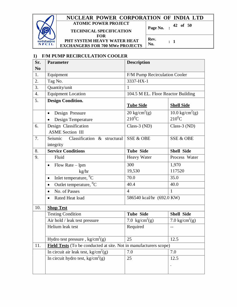
NUCLEAR POWER CORPORATION OF INDIA LTD ATOMIC POWER PROJECT
TECHNICAL SPECIFICATION
FOR
PHT SYSTEM HEAVY WATER HEAT
EXCHANGERS FOR 700 MWe PROJECTS
Page No. : 42 of 50
Rev.
No. : 1
1) F/M PUMP RECIRCULATION COOLER
Sr.
No
Parameter Description
1. Equipment F/M Pump Recirculation Cooler
2. Tag No. 3337-HX-1
3. Quantity/unit 1
4. Equipment Location 104.5 M EL. Floor Reactor Building
5. Design Condition. Tube Side Shell Side
Design Pressure
Design Temperature
20 kg/cm2(g)
2100C
10.0 kg/cm2(g)
2100C
6. Design Classification
ASME Section III
Class-3 (ND) Class-3 (ND)
7. Seismic Classification & structural
integrity
SSE & OBE SSE & OBE
8. Service Conditions Tube Side Shell Side
9. Fluid Heavy Water Process Water
Flow Rate – lpm
kg/hr
300
19,530
1,970
117520
Inlet temperature, 0C 70.0 35.0
Outlet temperature, 0C 40.4 40.0
No. of Passes 4 1
Rated Heat load 586540 kcal/hr (692.0 KW)
10. Shop Test
Testing Condition Tube Side Shell Side
Air hold / leak test pressure 7.0 kg/cm2(g) 7.0 kg/cm
2(g)
Helium leak test
Required --
Hydro test pressure , kg/cm2(g) 25 12.5
11. Field Tests (To be conducted at site. Not in manufacturers scope)
In circuit air leak test, kg/cm2(g) 7.0 7.0
In circuit hydro test, kg/cm2(g) 25 12.5
.
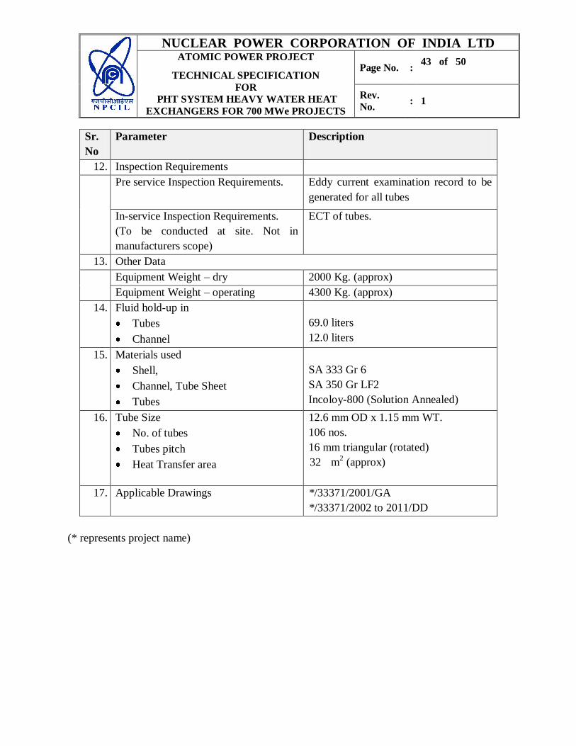
NUCLEAR POWER CORPORATION OF INDIA LTD ATOMIC POWER PROJECT
TECHNICAL SPECIFICATION
FOR
PHT SYSTEM HEAVY WATER HEAT
EXCHANGERS FOR 700 MWe PROJECTS
Page No. : 43 of 50
Rev.
No. : 1
Sr.
No
Parameter Description
12. Inspection Requirements
Pre service Inspection Requirements.
Eddy current examination record to be
generated for all tubes
In-service Inspection Requirements.
(To be conducted at site. Not in
manufacturers scope)
ECT of tubes.
13. Other Data
Equipment Weight – dry 2000 Kg. (approx)
Equipment Weight – operating 4300 Kg. (approx)
14. Fluid hold-up in
Tubes
Channel
69.0 liters
12.0 liters
15. Materials used
Shell,
Channel, Tube Sheet
Tubes
SA 333 Gr 6
SA 350 Gr LF2
Incoloy-800 (Solution Annealed)
16. Tube Size
No. of tubes
Tubes pitch
Heat Transfer area
12.6 mm OD x 1.15 mm WT.
106 nos.
16 mm triangular (rotated)
32 m2 (approx)
17. Applicable Drawings */33371/2001/GA
*/33371/2002 to 2011/DD
(* represents project name)
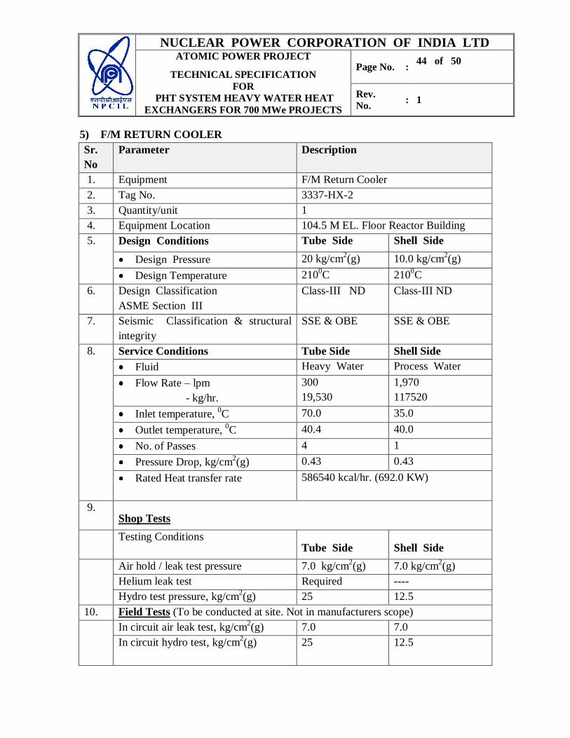
NUCLEAR POWER CORPORATION OF INDIA LTD ATOMIC POWER PROJECT
TECHNICAL SPECIFICATION
FOR
PHT SYSTEM HEAVY WATER HEAT
EXCHANGERS FOR 700 MWe PROJECTS
Page No. : 44 of 50
Rev.
No. : 1
5) F/M RETURN COOLER
Sr.
No
Parameter Description
1. Equipment F/M Return Cooler
2. Tag No. 3337-HX-2
3. Quantity/unit 1
4. Equipment Location 104.5 M EL. Floor Reactor Building
5. Design Conditions Tube Side Shell Side
Design Pressure 20 kg/cm2(g) 10.0 kg/cm
2(g)
Design Temperature 2100C 210
0C
6. Design Classification
ASME Section III
Class-III ND Class-III ND
7. Seismic Classification & structural
integrity
SSE & OBE SSE & OBE
8. Service Conditions Tube Side Shell Side
Fluid Heavy Water Process Water
Flow Rate – lpm
- kg/hr.
300
19,530
1,970
117520
Inlet temperature, 0C 70.0 35.0
Outlet temperature, 0C 40.4 40.0
No. of Passes 4 1
Pressure Drop, kg/cm2(g) 0.43 0.43
Rated Heat transfer rate 586540 kcal/hr. (692.0 KW)
9. Shop Tests
Testing Conditions Tube Side Shell Side
Air hold / leak test pressure 7.0 kg/cm2(g) 7.0 kg/cm
2(g)
Helium leak test Required ----
Hydro test pressure, kg/cm2(g) 25 12.5
10. Field Tests (To be conducted at site. Not in manufacturers scope)
In circuit air leak test, kg/cm2(g) 7.0 7.0
In circuit hydro test, kg/cm2(g) 25 12.5
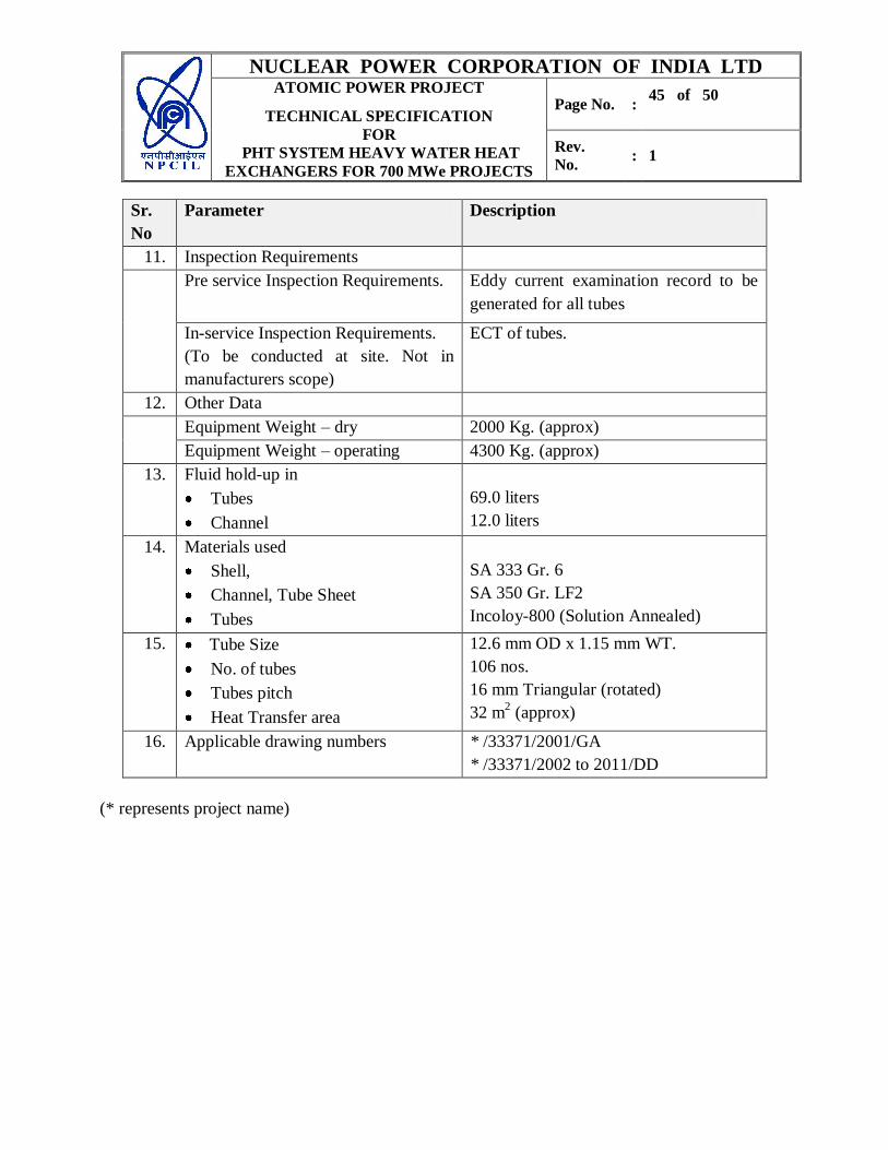
NUCLEAR POWER CORPORATION OF INDIA LTD ATOMIC POWER PROJECT
TECHNICAL SPECIFICATION
FOR
PHT SYSTEM HEAVY WATER HEAT
EXCHANGERS FOR 700 MWe PROJECTS
Page No. : 45 of 50
Rev.
No. : 1
Sr.
No
Parameter Description
11. Inspection Requirements
Pre service Inspection Requirements.
Eddy current examination record to be
generated for all tubes
In-service Inspection Requirements.
(To be conducted at site. Not in
manufacturers scope)
ECT of tubes.
12. Other Data
Equipment Weight – dry 2000 Kg. (approx)
Equipment Weight – operating 4300 Kg. (approx)
13. Fluid hold-up in
Tubes
Channel
69.0 liters
12.0 liters
14. Materials used
Shell,
Channel, Tube Sheet
Tubes
SA 333 Gr. 6
SA 350 Gr. LF2
Incoloy-800 (Solution Annealed)
15. Tube Size
No. of tubes
Tubes pitch
Heat Transfer area
12.6 mm OD x 1.15 mm WT.
106 nos.
16 mm Triangular (rotated)
32 m2 (approx)
16. Applicable drawing numbers * /33371/2001/GA
* /33371/2002 to 2011/DD
(* represents project name)
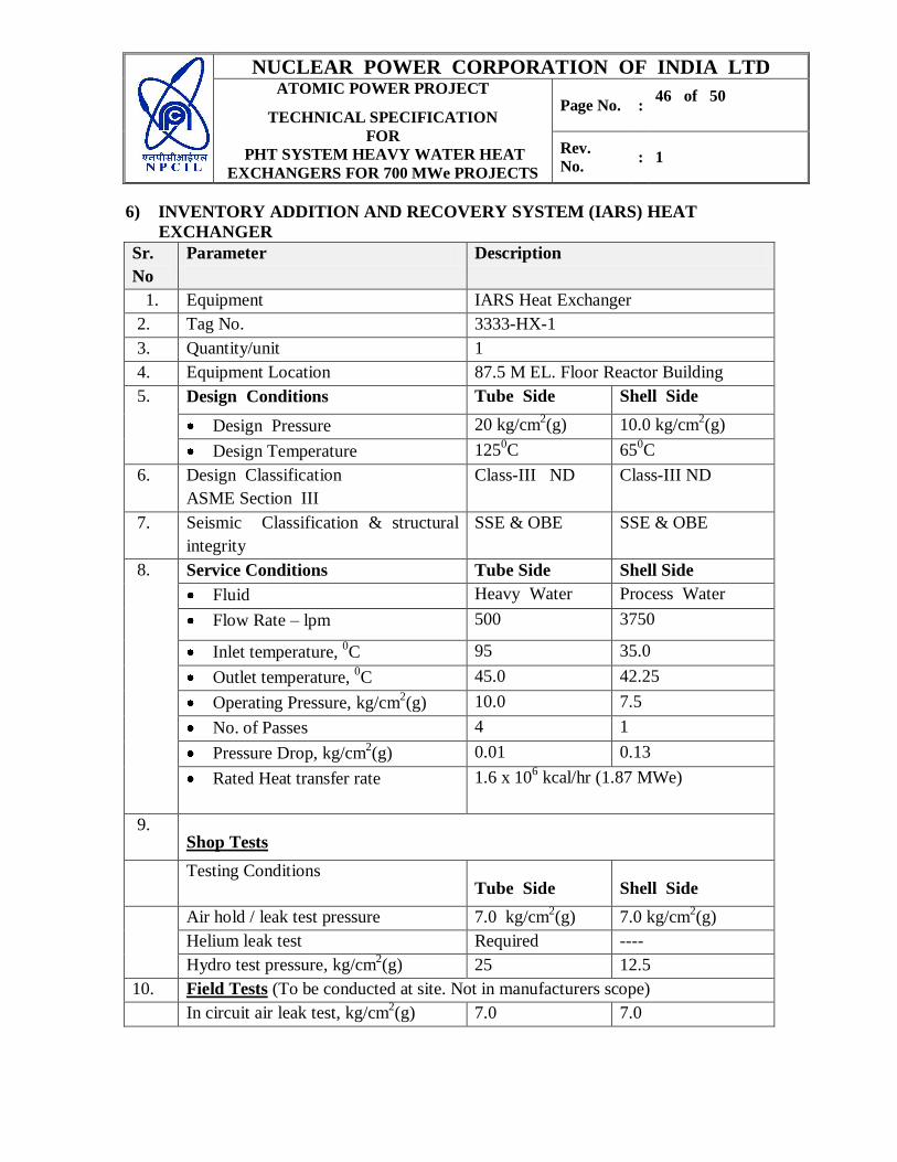
NUCLEAR POWER CORPORATION OF INDIA LTD ATOMIC POWER PROJECT
TECHNICAL SPECIFICATION
FOR
PHT SYSTEM HEAVY WATER HEAT
EXCHANGERS FOR 700 MWe PROJECTS
Page No. : 46 of 50
Rev.
No. : 1
6) INVENTORY ADDITION AND RECOVERY SYSTEM (IARS) HEAT
EXCHANGER
Sr.
No
Parameter Description
1. Equipment IARS Heat Exchanger
2. Tag No. 3333-HX-1
3. Quantity/unit 1
4. Equipment Location 87.5 M EL. Floor Reactor Building
5. Design Conditions Tube Side Shell Side
Design Pressure 20 kg/cm2(g) 10.0 kg/cm
2(g)
Design Temperature 1250C 65
0C
6. Design Classification
ASME Section III
Class-III ND Class-III ND
7. Seismic Classification & structural
integrity
SSE & OBE SSE & OBE
8. Service Conditions Tube Side Shell Side
Fluid Heavy Water Process Water
Flow Rate – lpm 500 3750
Inlet temperature, 0C 95 35.0
Outlet temperature, 0C 45.0 42.25
Operating Pressure, kg/cm2(g) 10.0 7.5
No. of Passes 4 1
Pressure Drop, kg/cm2(g) 0.01 0.13
Rated Heat transfer rate 1.6 x 10⁶ kcal/hr (1.87 MWe)
9. Shop Tests
Testing Conditions Tube Side Shell Side
Air hold / leak test pressure 7.0 kg/cm2(g) 7.0 kg/cm
2(g)
Helium leak test Required ----
Hydro test pressure, kg/cm2(g) 25 12.5
10. Field Tests (To be conducted at site. Not in manufacturers scope)
In circuit air leak test, kg/cm2(g) 7.0 7.0
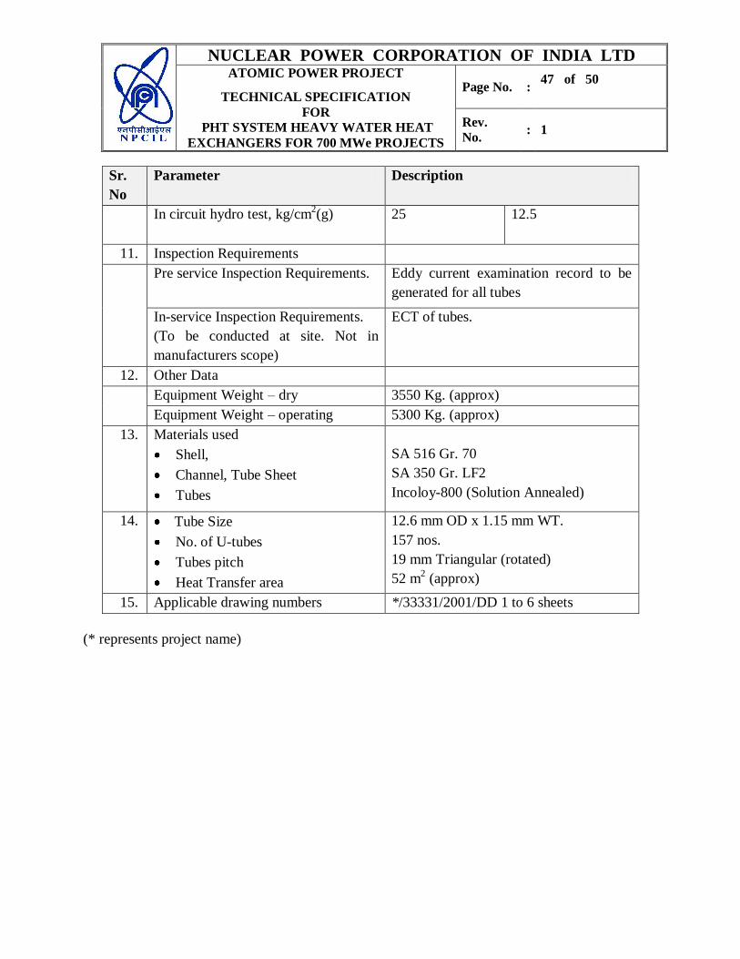
NUCLEAR POWER CORPORATION OF INDIA LTD ATOMIC POWER PROJECT
TECHNICAL SPECIFICATION
FOR
PHT SYSTEM HEAVY WATER HEAT
EXCHANGERS FOR 700 MWe PROJECTS
Page No. : 47 of 50
Rev.
No. : 1
Sr.
No
Parameter Description
In circuit hydro test, kg/cm2(g) 25 12.5
11. Inspection Requirements
Pre service Inspection Requirements.
Eddy current examination record to be
generated for all tubes
In-service Inspection Requirements.
(To be conducted at site. Not in
manufacturers scope)
ECT of tubes.
12. Other Data
Equipment Weight – dry 3550 Kg. (approx)
Equipment Weight – operating 5300 Kg. (approx)
13. Materials used
Shell,
Channel, Tube Sheet
Tubes
SA 516 Gr. 70
SA 350 Gr. LF2
Incoloy-800 (Solution Annealed)
14. Tube Size
No. of U-tubes
Tubes pitch
Heat Transfer area
12.6 mm OD x 1.15 mm WT.
157 nos.
19 mm Triangular (rotated)
52 m2 (approx)
15. Applicable drawing numbers */33331/2001/DD 1 to 6 sheets
(* represents project name)
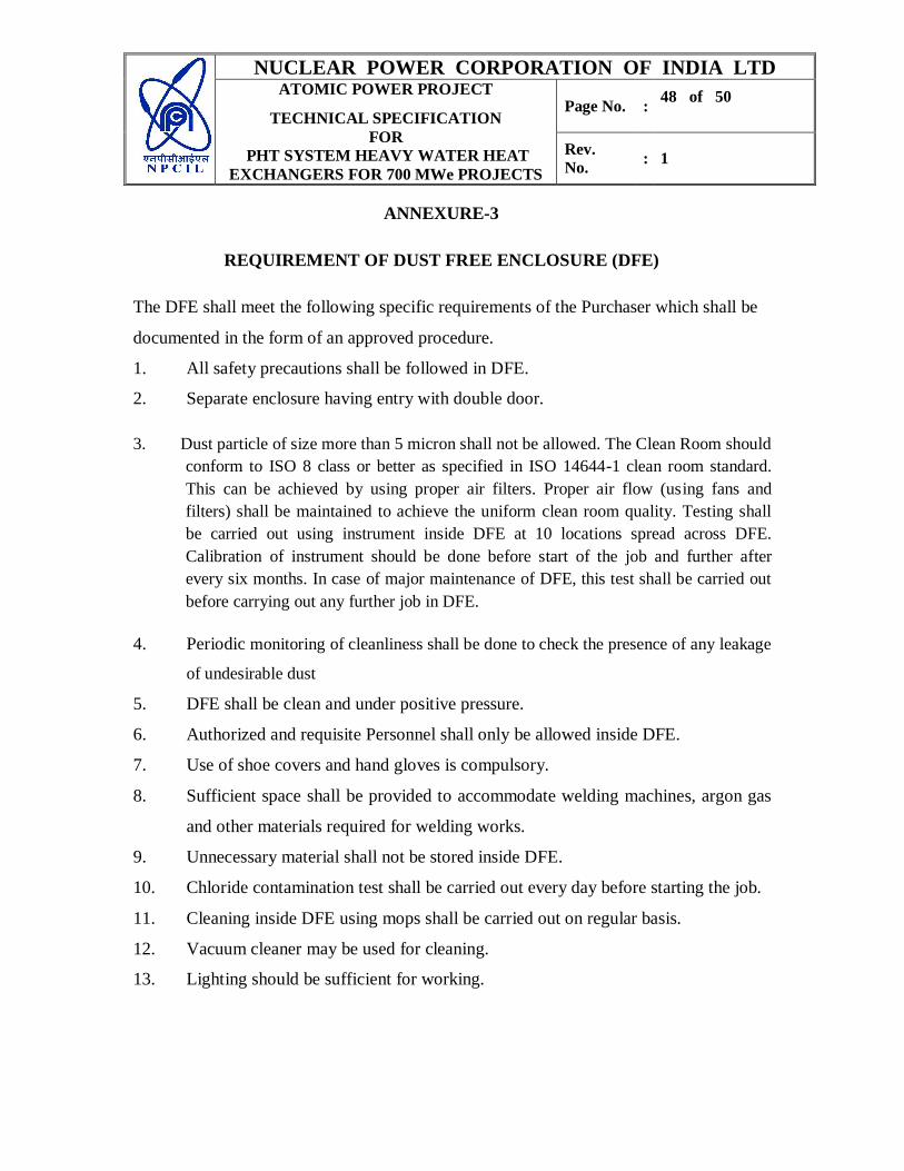
NUCLEAR POWER CORPORATION OF INDIA LTD ATOMIC POWER PROJECT
TECHNICAL SPECIFICATION
FOR
PHT SYSTEM HEAVY WATER HEAT
EXCHANGERS FOR 700 MWe PROJECTS
Page No. : 48 of 50
Rev.
No. : 1
ANNEXURE-3
REQUIREMENT OF DUST FREE ENCLOSURE (DFE)
The DFE shall meet the following specific requirements of the Purchaser which shall be
documented in the form of an approved procedure.
1. All safety precautions shall be followed in DFE.
2. Separate enclosure having entry with double door.
3. Dust particle of size more than 5 micron shall not be allowed. The Clean Room should
conform to ISO 8 class or better as specified in ISO 14644-1 clean room standard.
This can be achieved by using proper air filters. Proper air flow (using fans and
filters) shall be maintained to achieve the uniform clean room quality. Testing shall
be carried out using instrument inside DFE at 10 locations spread across DFE.
Calibration of instrument should be done before start of the job and further after
every six months. In case of major maintenance of DFE, this test shall be carried out
before carrying out any further job in DFE.
4. Periodic monitoring of cleanliness shall be done to check the presence of any leakage
of undesirable dust
5. DFE shall be clean and under positive pressure.
6. Authorized and requisite Personnel shall only be allowed inside DFE.
7. Use of shoe covers and hand gloves is compulsory.
8. Sufficient space shall be provided to accommodate welding machines, argon gas
and other materials required for welding works.
9. Unnecessary material shall not be stored inside DFE.
10. Chloride contamination test shall be carried out every day before starting the job.
11. Cleaning inside DFE using mops shall be carried out on regular basis.
12. Vacuum cleaner may be used for cleaning.
13. Lighting should be sufficient for working.
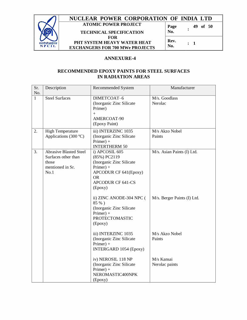
NUCLEAR POWER CORPORATION OF INDIA LTD ATOMIC POWER PROJECT
TECHNICAL SPECIFICATION
FOR
PHT SYSTEM HEAVY WATER HEAT
EXCHANGERS FOR 700 MWe PROJECTS
Page
No. :
49 of 50
Rev.
No. : 1
ANNEXURE-4
RECOMMENDED EPOXY PAINTS FOR STEEL SURFACES
IN RADIATION AREAS
Sr. No.
Description Recommended System Manufacturer
1 Steel Surfaces DIMETCOAT–6
(Inorganic Zinc Silicate
Primer) +
AMERCOAT-90
(Epoxy Paint)
M/s. Goodlass
Nerolac
2. High Temperature
Applications (300 ºC)
iii) INTERZINC 1035
(Inorganic Zinc Silicate
Primer) + INTERTHERM 50
M/s Akzo Nobel
Paints
3. Abrasive Blasted Steel
Surfaces other than
those mentioned in Sr.
No.1
i) APCOSIL 605
(85%) PC2119
(Inorganic Zinc Silicate Primer) +
APCODUR CF 641(Epoxy)
OR APCODUR CF 641-CS
(Epoxy)
ii) ZINC ANODE-304 NPC ( 85 % )
(Inorganic Zinc Silicate
Primer) + PROTECTOMASTIC
(Epoxy)
iii) INTERZINC 1035 (Inorganic Zinc Silicate
Primer) +
INTERGARD 1054 (Epoxy)
iv) NEROSIL 118 NP
(Inorganic Zinc Silicate Primer) +
NEROMASTIC400NPK
(Epoxy)
M/s. Asian Paints (I) Ltd.
M/s. Berger Paints (I) Ltd.
M/s Akzo Nobel Paints
M/s Kansai
Nerolac paints
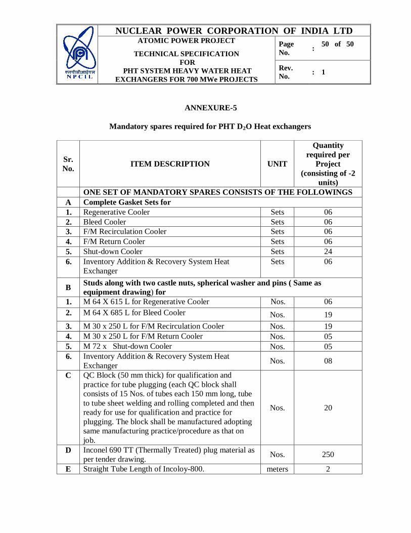
NUCLEAR POWER CORPORATION OF INDIA LTD ATOMIC POWER PROJECT
TECHNICAL SPECIFICATION
FOR
PHT SYSTEM HEAVY WATER HEAT
EXCHANGERS FOR 700 MWe PROJECTS
Page
No. :
50 of 50
Rev.
No. : 1
ANNEXURE-5
Mandatory spares required for PHT D2O Heat exchangers
Sr.
No. ITEM DESCRIPTION UNIT
Quantity
required per
Project
(consisting of -2
units)
ONE SET OF MANDATORY SPARES CONSISTS OF THE FOLLOWINGS
A Complete Gasket Sets for
1. Regenerative Cooler Sets 06
2. Bleed Cooler Sets 06
3. F/M Recirculation Cooler Sets 06
4. F/M Return Cooler Sets 06
5. Shut-down Cooler Sets 24
6. Inventory Addition & Recovery System Heat
Exchanger
Sets 06
B Studs along with two castle nuts, spherical washer and pins ( Same as
equipment drawing) for
1. M 64 X 615 L for Regenerative Cooler Nos. 06
2. M 64 X 685 L for Bleed Cooler Nos. 19
3. M 30 x 250 L for F/M Recirculation Cooler Nos. 19
4. M 30 x 250 L for F/M Return Cooler Nos. 05
5. M 72 x Shut-down Cooler Nos. 05
6. Inventory Addition & Recovery System Heat
Exchanger Nos. 08
C QC Block (50 mm thick) for qualification and
practice for tube plugging (each QC block shall
consists of 15 Nos. of tubes each 150 mm long, tube
to tube sheet welding and rolling completed and then
ready for use for qualification and practice for
plugging. The block shall be manufactured adopting
same manufacturing practice/procedure as that on
job.
Nos. 20
D Inconel 690 TT (Thermally Treated) plug material as
per tender drawing. Nos. 250
E Straight Tube Length of Incoloy-800. meters 2