This page intentionally left blank - Energy · ~teamwreuaw€punflpr~euppernr%wk diswbal cell....
42
LONG-TERM SURVEILLANCE PLAN FOR THE UPPER BURBANK DISPOSAL CELL URAUAN, COLORADO July 1999 Prepared for U.S. Department of Energy Environmental Restoration Dhrision U MTRA Project Team Albuquerque, New Mexico DOElAU62350-250 REV. 1 Prepared by Jacobs Engineering Group Inc. Albuquerque, New Mexico
Transcript of This page intentionally left blank - Energy · ~teamwreuaw€punflpr~euppernr%wk diswbal cell....
LONG-TERM SURVEILLANCE PLAN FOR THE UPPER BURBANK DISPOSAL CELL
URAUAN, COLORADO
July 1999
Prepared for U.S. Department of Energy
Environmental Restoration Dhrision U MTRA Project Team
Albuquerque, New Mexico
DOElAU62350-250 REV. 1
Prepared by Jacobs Engineering Group Inc.
Albuquerque, New Mexico

This page intentionally left blank
LONG-TERM GURMIWNCE P U N FOR THE UPPER BURBANK DrsPosAL CEU. WYAAI. COhORAOD TABLE OF DONENTe
TABLE OF CONTENTS
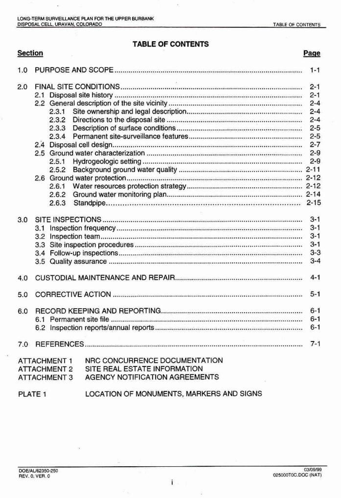
1.0 PURPOSEANDSCOPE .............................................................................................. 1-1
2.11 FINAL SlTE CONDITIONS ................... ...-.... ...............................................*.............. 2-1 ..................................................................... ................... 2. 1 Disposalsitehislory .. 2-1
..... 2.2 Gleneraldewri'ptionofthesitevicinity .................................................. ...... 2-4 ......................................................... 23.1 Slte ownership and legal description 2-4
2.3.2 Dir&ionstothedisposalsite .................................................................. 2-4 2.3.3 Description of surface conditions ............................................................. 2-5
....................................................... 2.3.4 Permanent site-sumeillance features. 2-5 2k Disposal cell design ............................................................................................... 2-7
........................................................................... 2.5 Ground'.water characterization 2-9 2.5.1 Hydrogeologic setting ............,..................................... ..................... 2-9
......................*.*..... .......*...................*.. 2.5.2 Background ground water quality 2-11 2.8 Ground water protecWn ..................................................................................... 2-12
..................... ........-.-.-........... 2.6.1 Water rewurces protection strategy .l.... 2-12 2.6.2 Ground water monitoring plan ................................................................... 2-14 2.6.3 Standpipe ............................................................. .; ................... 2-15
................... .... ............*............*.*............................... 3.0 SITE INSPECTIONS .... .. 3. 1 Inspection frequency ......................... ........... ........................................................ 3.2 Inspection team .................................................... ....-... .................................... 3.3 Site inspection procedures ..............................................................................~.. 3. 4 Follow-up tnspedons ........................................................................................... 3.5 Quality assurance ................................................... ...
4.0 CUSTODIAL MAINTENANCE AND REPAIR ............................... ... ...........
6.0 RECORD KEEPING AND REPORTING ...................................................................... 6.1 Permanent site fik ........................... .,.........................~...............+........ ........... 6 2 Inspecdon repoWannual repatts ............~....~.............................................~.........
7.0 REFERENCES .................................... ...,.. ...................................................................
ATTACHMENT 1 NRC CONCURRENCE DOCUMENTATION ATACHMENT2 SrrEREALESTAxlNFORMATlON ATTACHMENT 3 AGENCY NOTIFtCATION AGREEMENTS
PLATE 1 LOCATION OF MONUMENTS. MARKERS AND SIGNS
D W A l m 3 E w 5 0 03mm REV . 0 . VVER . 0 ~ f ( # : . W C (MAT)

LONO-TERM W Z I U 1 J C E PLAN FOFl THE BORBANK OIWOSAL CELL LRAVAN, CQUWlAbb LIST OF n ~ u m
LlST OF FlWRES
Finure
....................................... 2,1 Regional map showing location of the Burbank disposal cell 2-2 2.2 Locationof theUpprBurbankdisposalsite .................................~............................. 2-3
................................. 2.3 Monitor well locations in the Club Mesa area, Uravan, Colorado 2-8 .................. 2,4 Hydrogeolugic cross section at the Upper Burbank site Uravan, Colorado 2-1 0
3.1 Steps for follow-up inspections, custadial maintenance, and corrective ........................................ action, Upper Burbank disposal site near Uravan, Colorado 3 2
LlST OF TABLES
Tabk
2.1 Locations of pemanent surveilfanw feafures, Upper Burbank disposal cell, ................................................. ............... U ratlan, Colorado .................. ..... .~. . .~~., . . , . , .II. 2-6
2.2 Hazardous~wnsWents and concentration lknits for ihe POC at the Upper Burbank dispomlcell, Uravan, Cotorado ....................,.,,,., ..................................................... 2-13
LIST OF PLATES
Plaftr I
Location of monuments, markers and signs.
DWALE629X)-290 03WW REV. 0. VER. 0 025woToc.aoc WA7)
ii

~ T E A M W R E U A W € P U N F l P R ~ E U P P E R N R % W K DISWBAL CELL. WV\VAN, LIST OF ACRONYMS
LIST OF ACRONYMS
BLM BMP DOE €PA LTSP MCL NGVD NRC PQC CIA RAP SOP TAC UMTRA UMTRCA RRM
US. Bureau of I m d Management best management practice U.S. Department of Energy U .S. Environrnenbl Protection Agency long-term wrveillanm plan msximurn conwntration limb National Geodetic Ve~%cal Datum U.S. Nuclear Regulatory Commission point of compliance quality assuranw remedial action plan standard aperating procedure technical assistance contractor Uranium Mill Tailings Remedial Action Uranium Mill Tailings Radiation Control Act residual radioactive material

LONG-TERM S U R E t W E PLAN FORT HE UPPER BURBANK DISPOSAL CEU. URANVAN. CDLMIAI30 Change History
CHANGE HISTORY
Rev 0 Ver 0 91 1 4/98
Rev 1 VerO Incorporates NRC. GJO and CDPHE comments
DOEIAW2350-260 0711369 REV. 1, VER. 0 025030HS 1NATj

~ t W M W ~ P U P l W R ~ U P P E R B U R A N r ( WW&ALQLL. URWAW. CoLoMDo WAWSE AND SCOPE
1.0 PURPOSE ANDSCOPE
This long-term surveillance plan (LTSP) describes the U.S. Department of Energy (DOE) long- term care program far the Uranium Mill Tailings Remedial Action (UMlRA) Project Upper Burbank disposal cell near Uravan, Colorado. This disposal cBH conlains mateHals from the Naturita, Colorado processing site.
The US, Nuclar Regulatory Cornmisslon (NRC) dsvdoped regulations for tfw issuanca of e general license for the custody and long-term care of UMTM Project disposal sites in 10 CFR Part 40. The purpose of this general Iiamse is to ensure that the UMTW Project disposal sites are cared fw in a manner that protect$ the public health and safety and the environment. Before saeh disposal s b Is licensed, the NRC requires the DOE tp submit a site-specific tT8P. The DOE prepared this LTSP to meet this requirement for the Upper 6urbank disposal d l . The general license becomes Mective when ths NRC concurs with the DOE determination that remedial action is complete at the Upper Burbmk disposal cell and the NRC formally accepts this LTSP. Attachment 1 contains the concurrence letters from NRC,
This LTSP describes the long-term suweillance program the DUE will implement to ensure that the Upper Burbank disposal cell performs a$ designed. The program is based on site inspections to identify threats to dbposal cell intsgrrfy. Ground water rnonltorhg will be conducted. The LTSP is based on the UMTRA Project long-term sunreillmce program guidance (DOE, 1 W6a) and meets the requirements of 10 CFR §40.27@) and 40 CFR 51 92.03.

LOA#TJEW WPVEltLAblCE FOR THE U r n BWI- m s ~ t c n ~ IJWVAN~ COLORMO WAL SITEMMDITIQMS
2.0 FINAL SITE CDNDITIUMS
Remedial a'ction at the f a m r uranium prmming site loceted near Naturita, C d o d o c a n s W of bemolMing exbting facilities;, M a t i n g aubpib and windblown material from the site and ad- properties, and relocating the residual mdi-e materials to the Upper Burbank disposal cell at Urnan, ~lurado, The DOE eon- a disposal aell to cmtmL this residua! Woactive material in amrdance with 4 CFR Part 192. The Upper Burbatik disposal sib is barbwire fc~ncled, and i& perim@et is madd w b warning sQm. The she complq:fi~n report contains a detailed description of the final siB conditions (MK-F, 1998).
DISPOSAL $!TE HISTORY
The Upper Burbank disposal call is locabd approximately 13 road miles (21 kilometers) nadhwest af t k Naturita pr;ooesslng she (Figure 2.1 1, The Upper Burbank site is Iuafed on property formerly olrvnetj by the Umeb Minerals Corporation. Dun'ng remediation of uranium mill tailings at the Urnvan she, Umeb decided to dewlap the Burbank' Pit as a bmw awrae for sandstone rock for use as erosion ptotedon on the slopes of U m n Disposal Cells 1,2, and 3. The! Burbank Pit is ,located near the south end of the Club Mesa adjacent to Hieroglyphic Canyon, and was excavated fram the south end at the c a n p rim northward towlard the center of the mesa, After excavation of the required sandstom mabrSal from the Burbank Pit, s 'U" shaped hole was famed [Figure 221. Umetm used the lower (southern and) of the Burbank Pff for disposal of mfftnaw crystals fm the upper part of Club , M w , leaving the upper (northern) end of the pit available for consfructlon df the fit18 1 Project disposal a H . Hence, the site for materials from the Naturita processing site was called the U p p l Burbank dkposal mIJ.
The Upper Burfrank dispoaai cell is unique h that KMs or na tailings mzltwials am . contained in the disposal cell This is -use he orlgtnal Blrmgs stored a1 he Matufi processing site were, pumhasd and r m v d for processing at ttla nearby Durita Site by Ranches Bplwation arid Development, The remaining su bpile matmial, condstihg of soits in #he Wll yard, OW storage area, tailings $ile areas, windblown tailings adjacent to the site, building debtis from demolition of the mill buildings, and mlll equipment s t o d m site make'up the contaminated material hauled to the Upper Burbank disposal cell.
Surface remedial a&on at the MaluriQ processing site began in June 1896 and ended in Nwember 1997'. Final site grading and seeding of the disposal slte was completed h the summer and fall 1938. Disposal cell construction was essentially completed k July I 998 with pfacernent of Anal ltAs of fiast protedion material on We south end of the cell. AppmrOXlrnately 800,000 yd3 (61 0,000 ma) of material Were placed in the disposal cell and compacted ,to a volume of approximately 680,000 yd3 (520,000 ma).
The Uranium Mill Tailings Radiation Control Act (UMTRCA) d 1978 gave the DOE authority to perform remedjal d o n at the Natutita p m s i n g site (42 USC 7901 et seq.). The DOE evaluated the environmental impacts aswciated with athe rerrPertial a& in an environmental awmmnt (DOE, 1994). The NRC and the stab, of Colorado mncurfed with the DOE remedial mun plan (W) (DOE, 1 W8) tw comply with the mquiremenfs of 40 CFR Part 1 92, Subpa& A through C.

LEGEND
@ STATEHIGHWAY
-- EPHEMERAL STFIEAM
COLORADO
M a p b d l o n
FIGURE 2.1 REGIONAL MAP SHOWNG LOCATION OF THE BURBANK DISPOSAL CELL

1000 ' 0 1000 FEET - 500 0 500 METERS
SChLE CONTOUR INTERVAL : 50 FEET
FIGURE 2.2 LQCAnON OF THE UPPER BURBANK DISPOSAL SITE '
URAVAN, COLORADO
LOHETEAM S U R V E U N E P U N WR 7l-E WPW @llR&NK MWaQAF CELL, URAVAN. CDLORAIK] FINAL SITE CONDmDNS
The DOE prepared a completion report documenting mmpiiance with the remadial action pian and the site =-built aondiitons (MK-F, 1998). The DOE alrw prepamd a final audit repori and certification summary and submitted it and the wrnpletjan report to the NRC for ooncurnnw. NRC conwrrelrm on the certification report is included in the permanent site file. (Attachment 1)
GENERAL DESCRIPTION OF THE SlTE VlClNrrY
The Naturita processing and disposal site8 am lomted h Montroae County, which is a predominately rural county in &em Colorado with a population of 24,423 (United States Census, 1 WO), The Uravan area b sparsdy populated, with no permanent residenoes within 5 miles (8 km) af the disposal Me. Much of the land is held by the BLM and is leased to ranchers for grazing. The dominant land uses are livestock grazing and a minor amount of mining, Historically, mining was aetivrt ln the area and numerous abandoned mines and mining roads are located near the Ate.
DISPOSAL SlTE DESCRIPtlON
The Upper Butbank disposal site is located In the northerly end of a rock quarry de~eloped by Umetco to produce erosion protalon rip rap for their Title I! disposal cells. Being a quarry pit, the site is basically a large hole excavated into solid bedrock along the southern rim of Club h a with rock slopes on t h r e sides and an open end that borders Urnem's crystal storage cells (Figure 2.2).
A legal description of the DOE property that contains the Upper Burbank disposal site shown In Attachment 2, The plan view d the property Is shown on Plate 1.
Directions to the d i d slte
The Upper Burbank disposal site can be reached by automobile vla paved roads by fallowing these directions:
1. Take Colorado State Route 141 northwest out of the town of Naturita approximately 15 miles (24 km) to Uravan.
2. Turn left (west-southwest) toward ?he old Uravan site on County Road EE22. Almost immediately after leaving highway 141, there is a metal bridge crossing. Bear to the right and go up EE22 along a narrow road that hugs the rim of Hieroglyphic Canyon approximately 1.6 miles (2.6 km).
3. Near the top of the canyon, EE22 makes a sharp turn to the right (northwest) and goes out of the canyon toward the top of the mesa, The Burbank disposal dte is located a few hundred feet after the turn, just to the left of EE22.

L W T E R M SWIVEILLAWCE PLAN WR M E UPPER BURBPLNK MSWSAL CEU, URAVAH, COLORADO FINAL SITE CONMT1O$I5
Prior to start of construction of the Upper Burbank disposal cell, the bottom of the Butbank pit was cwered with a day finer (previously installed by Umetm). To prevent ponding on this day layer and allow free drainage (see groundwater protection strategy in section 2.6.1), the clay liner was removed (by Umetco), and b e bottom of the excavation was scraped into the top 05 intact sandstone bedrack. At the start of construction, slopes along the north, east, and west sides of the site were either inhd sandstone bedrock br dl and rock rubble mver over intact sandstone. To help limit the amount of Silt and rack debris that could b& washed on the disposal site by the Maximum Probabb Flood, these dopes were cleaned of loose material to the bedrock surface or cut to a stable slope ,angle-
Stoops and adits from t k nearby Cotter mihe workings an be seen along the western side of the site. An airshaft from the Cotter mine located above the w&em corner of the she, caused the western end of the intemptar ditch to be redesigned during construction-
Suwey and boundary monuments, site markers, and warning signs are the permanent long-term surveillance features of the Upper Burbank disposal site. In addition, the disposal Ate also has background ground water monitor wells. Plate 1 shows the lacations of these features and Table 2.1 provides their survey grid coordinates. Typical construdtCan and installatlan specifications far these features are shown in the long-term surveillance guidanoe (DOE, 1996aj and subantract documents (MKXCE, 1998).
Three survey monumohls establish permanent horizontal control based on the Union Carbide North Uravan DisHct Caordinate System, established by others. The three permanent survey monuments (SM-3, SM-4, and SM-1 I) are b r n b n RT-1 markers set in concrete with the rmnument approximately 4 inches (in) (10.2 centimeters [cm]) above the ground level. Magnets in the markes will permit easier detection 'if they become buried over time. The survey monument identification number is stamped on the top ~f h e metal cap.
Fourteen boundary monuments lie along the final site boundary, These monuments are Berntsen Model A-l survey monuments set in concrete with the monument approximately 7 inch (2.5 cm) above ground level. Magnets in the A-1 monuments will allow easier detection if they become buried. The bwndary monument identification number is stamped on the top of the metal cap. Boundary monuments are offset five-feet inside the site boundary.
Two unpolished granite markera with an incised message identify the Upper Burbank disposal cell. The message includes a drawing showing the general !omtion of the stabilized disposal dl within the site boundaries, the date of dosure, the weight of tailings (971,762 dry tons f081,405 metric tans]), and the amount of radioactivity (79 curies of radium-=). Site marker SMK-1, near the north end of

0c
Ym
tm
cp
r-
~
=Y
~?
?T
~T
T-
~T
TT
I
Z~
ZI
I~
~Z
~S
~I
I
mm
mm
mm
m
mm
mm
mm
LONQ-TERM SURVEIUNCE PLAN FOR THE UPPER 3URBANK DISPOSAL CUL, LIRAVAN. COLORADO RMAL SITE CONDITIONS
the diversion channal, is set in reinfomed concrete that extends 3 ft (0.9 m) below the ground surface. sits marker SMK-2, at the crest of the disposal cell, is set in reinforced concrete that extends to the top of the frost-protection barrier.
The DOE-posted warning signs (1 8 x 24 inches [6f x 46 cm]) indicate property use around the disposal site perimeter. The site entrance sign displaying the DOE 24- hour telephone number is at the east access gate near sunrey monument SM-4. In addition to the entrance sign, 23 perimeter warning signs are located approximately 5 fl(1.5 m) inside the site fence at approximately 200-ft (60-m) intenrals. T,he warning signs are mounted on steel posts with the tops of the signs approximately 6 ft (2.0 m) above the ground surface. The sign posts are embedded in concrete to a depth of approximately 3 ft (1.0 m) below ground surface.
The Upper Burbank disposal cell has one point of compliance monitor well (CM93- 21, one background well (CM93-11, and three ground water-level monitor wells (BR95-1, BR95-2, and BR95-3). Umetco Minerals company installed and developed the five monitor wells. Figure 2.3 shows approximate location of monitor wells h the Club Mesa area.
The approximately 10-acre (4-ha) disposal cell is located near the southern rim of Club Mesa in the upper end of the Burbank pit. Upland drainage has been directed away from the disposal cell by grading of the borrow areas and construction of an interceptor channel. For details of upland drainage, refer to the Completion Report (MKF, 1998). The disposal cell was designed with erosion protection features to resist the probable maximum precipitation (PMP) event. Sandstone rock was used above the interceptor ditch, in construction of a sediment trap dam to the southwest of the cell, in an energy dissipation pad to the west side of the cell, and in a narrow band around the disposal cell. This sandstone rock was not considered to be erosion protection riprap, rather its purpose was for flow velocity reduction, energy dissipation, and sediment reduction before the PMP runoff flow reached the erosion protection rock. The erosion protection rock, designated as types A, B, and B1 on the plans, was tasted and meets NRC rock suitability scoring requirements. The sandstone rocks do not; and they do not need to meet these requirements because they are not designed to function as erosion protection rock.
W W ~ 5 0 - 2 5 0 oww99 REV. 0, VER. 0 WSOWS02[HAT)
2-7


RRM placed in this disposal cell are subplle mila; and wind blow contamination mnsistlng primarily of granular matsrisl such as silty sand, sand, sand and gravel, and oobble sized rock. Some clayey silt soil was placed in the cell, but this 'material was from the fiwgcained flood plain daposit~ axlstlhg at the processing site. No actual tailings were pieced in the Upper Burbank dlspoml cell and no mrnprwsible, wet slimes or fine silty W r i a l s are pwsent to cause problems with excessive settlement cover cracking or seismic liquefaction.
The disposal cell was designed to d s t seismic forces. The on-site peak horizontal acceleration wed in cell design was 0.28g.
bmuw of the relatively high plasticity index (PI = 40+) of much of the radon barrier soils, there was some concern for radon batrler mcking due to dtying of the redon barrier layer with time. The erosion protection layer on top of the disposal cell acts like a rock mulch, and tends to retard surface evaporation which auld dry out the cover layers of the disposal cell. Placement of a 5.5-foot (1 -7 m) thick freeze-thaw barrier over the radon barrier protects it from seasonal moisture fluctuations. Placement of the clayey radon barrier layer over coarser RRM layers forms a ciapillary beak that tends to maln#aR moisture In the radon barrier layer. So long as the moisture cantent of the mdan barrier layer remains relatively constant, and if domn't dry out to below the clayey's Shrinkage Limit, cover cracking of the radon barrier layer due to drying will not occur.
GROUND WATER C ~ C T E R I Z A T I O N
Urnetco Minerals Corporation has Maracterixed the hydrogwlagy, aquifer properties, geochemical wnditbns, water quality, and water r ~ u ~ at the Upper Burbank disposal site at Uravan, Colorado. This infomation is summarized below, wlth details provlded in Appendices 6 and C of the RAP (DOE, 1988).
The uppermost aquifer beneath the Upper Burbank disposal site is the sandstone of the Triassic Wingate Formation (Figures 2.3 and 2.4). Ground water occurs in the uppermast aquifer under unconfined conditions. Depth to gmund water in the uppermmi aquifer beneath the disposal site is approxim~tely 600 ft 180 m). The 5 hydraulic conductivity of the Wingate aquifer Is 0.1 2 Wday (42 x 10- cm/sec). Ground water flows in a no7therly direction beneath the site with an average gradient af 0.01 8 at an average linear velocity of 8 Wyr (2.4 Wyr) (assuming an e4fective porosityof QO,lD) t m r d the San Mtguel River, At this rate, ground water currently beneath the d'kposal site will not discharge into the San Miguel River for over f 000 years. The combination of low annual precipitation, high evaporation potentiaf, and the moisture deficiency (unsaturated mnditions) in ro& unib in the area indicates that significant ground water recharge does nat occur in the vicinity of the disposal site. hother Indication af the absence of long-term effects of infiltration into the Wlngate aquifer is the lack of any Indication of ground water contamination resulting from the extensive mining of radkrrn, uranlurn, and vanadium, along with related mineral processing activities in the Club Mesa area.
D w M m 3 5 b 2 6 0 mmm9 A N . 0, VER. D , a Z m ( N A r )
2-8

VPPER
CLUB MEsA
2~ m n c a EEXAQGERATW SOURCE: UMETCa RAP APPENDIX 0
FIGURE 2.4 HYDROGEQLOGIC CROSS SECTION AT THE UPPER BUFlBAPlK SITE
URAVAN, COLORADO

LONG-TERM SURVElLLANCE RAN FOR THE UPeER BURBANK DISPOSAL CELL. URAVAN, COLORAIX) RNAL SITE CONOITIONS
Residual radioactive material In the disposal cell lie on interbedded sandstone, siltstone, and mudstone strata of the Salt Wash Member af the Jurassic Morrison Formation. The Salt Wash is underlain by the Jurassic Surnmerville Formation, an aquitard consisting of approximately 90 ft (27 m) of massive dayey mudstones, silty shales, clayey siltstones, and minor interbedded sandstones. Field tests indicate a low hydraulic conductivity of 0.01 Wyr (I -0 x 1 O4 cmlsec) for the Summenrille. The top of the Summerville Is approximately 100-ft (30 m) beneath the surface. The Salt Wash and the Summerville are exposed in the hillside forming Club Mesa. Some water exists in the sandstone units of the Salt Wash and at the contact of the Salt Wash and the Summerville, but is relatively transient in nature. The Jurassic Entrada Formation lies between the Surnmerville and the Kayenta, and is unsaturated.
Any water infiltrating into the Salt Wash as recharge, from direct precipitation, surface runoff, or seepage from the tailings or other remediated materials, tends to migrate downward through the Salt Wash to the cantact with the Summewille aquitard, then laterally to discharge as seepage along the hillside. This seepage is currently collected in drainage ditches along the hillside and transported to evaporation ponds in the river valley. The Surnrnewille acts as an aquitard, providing hydrogeologic isolation, and minimizing migration of contaminants downward into the uppermost aquifer beneath Club Mesa. Geochemical conditions beneath the site are conducive to effective attenuation of contaminants in the seepage liquids.
Ground water from beneath the disposal site is not a current or potential source of drinking water because of the relatively high total dissolved solids (ranging from 3400 to 4860 mglL) and the depth to ground water (approximately 600 ft [I80 m]). Also the relatively low hydraulic conductivity of the aquifer of 0.12 ftlday (4.2 x t Om5 cmlsec) would restrict development of ground water resources beneath the site. There are no domestic or stock wells in the saturated zone of the Wingate aquifer within a 2-mi (3.2-km) radius of the site. Four industrial wells owned by Urnetco are present in the area, but will eventually be plugged and not available for future use. The Uravan site is located in a remote area approximately 12 mi (19 km) from the nearest towns, Naturita and Nucla. The nearest residence to the site is approximately 5 mi (8 km) to the east-southeast (upstream and upgradient). Because of the nature of the terrain and the demise of the uranium industry. there is no reason to believe that there will be any significant population increases with 10 mi (I 6 km) of the site in the foreseeable future.
Backaround around water quality
Background ground water quality in the uppermost aquifer (Wingate) has been determined from monitor wells in the vicinity of the Upper Burbank disposal site (CM93-1 and CM93-2) and downgradient from the disposal site (V768 and V769). Water qualrty data are available from September 1993 through December 1995 for monitor wells CM93-1 and CM93-2, and from April 1991 through December f 995 for monitor wells V768 and V769 (Appendix C, NAT-GW-002). Results of laboratory analyses indicate that concentrations of constituents of potential concern are below the MCLs. Background levels have been determined far those constituents without
00EIALlB2350-250 0711 3/99 REV. 1, VER. 0 02SOCIDSO2WTl
2-1 1
LONG-TERM SURVWP1CE PIAH FOR 7tE UPPER BWEWF DISP'C~GAL m u , URAVAN, COLQRA~~ FINAL SITE CONDIMS
MCLs (Table 22). Thw, there does not appear to be wntsmlnatlon in gmund water in the uppermost aquifer beneath the dieposal site on Club Mma reiated to the uranium processing and remediation activities.
The geochemical properties of soils and lithologic rnatwiak beneath the Upper Burbank disposal site will control the twlubility and adsorption of contaminants that couEd leach from the residual wdioactive materials Geochemical attenuation of the leach- would occur 8s liquid percolat~ through the bedrock formations by unsatumted flow, Calcium carbonate Gement in the Salt Wash sandstones would bufferany mlutions exiting the disposal cell. In summary, the Wingale aquifer would be protected from migration af any potential contamItmtion f m the disposal cell by the hycirogeologb idation provided by the low-pemeabillty shale and siltstone of the Summenrills aquttard and geochemical attenuation 01 hamrdum constituents in initial minor trmient drainage and in design of the disposal cell.
GaROUND WATER PR0TeCTK)N
The water resources protection strategy for the Upper Buhank disposal site is tg meet MCts or background levels at a point of compliance (POC) in ground water in the uppermost aquifer (Wingate Formation) hydraulically downgradient from the disposal cell, Ground water in the uppermost aquifer is etpproximat~!y 600 ft (1 80 km) beneath the base of the disposal cell. The uppermost aquifer is hydrogeologically Isoliqted from recharge by surface watw or potential transient drainage from the disposal cell by unsaturated sandstone and confining shale layers.
In accordance with 40 CF R $192,03, the DOE will implement a ground water monitoring plan, to be carried out m r a perid of time commencing upon completion of remedial actions taken to cmply with the standards h 40 CFR #192.02, and of a duraliwr which is adequate to demonstrate that future performance of #the system of disposal can reasonably be expected to he in accordance with the design requirements.
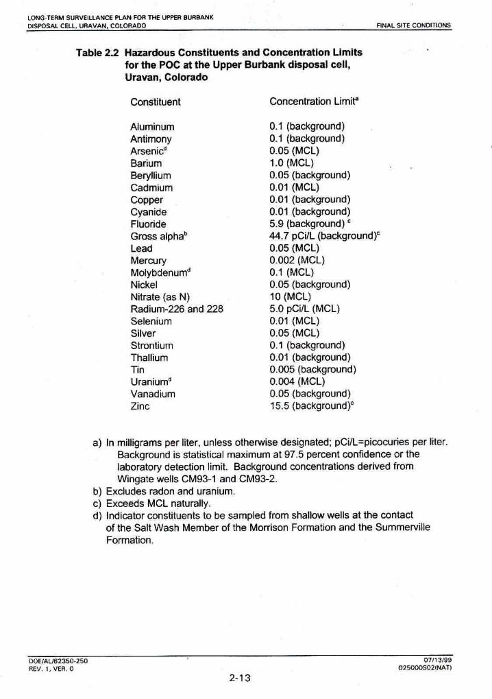
Compliance wlth ttle ground water protection standam requires determination of potendally hazardous constituents in the diossll cell, proposal of a concentration tlmlt for each hazardous constituent and spedfication of a POC in the uppermost aqutfer hydraulically downgradierrt of the disposal area.
The DOE has determined those mstltuents listed in Table 1 to Subpart A and Appendix I to Part 192 (40 CFR §I 92.02(~)(3)) that are present in or reamnrably derived from residual radioactive materials, and has determined background levels of each such mnstituent in ground W e r beneath the disposal site. The ltst of hazardous constituents proposed for the POC at the Upper Burbank disposal cell is sham in Table 23,
M>Vm350.25(1 umaw REV. 0. YER. 0 WWsb2fNAfl
LONCGTERM SWIYEILIA- PLAN FOR W E UPPER BURBAN DISPOSAL CELL VWYAIY, COLORADO IWAL SITE MUDIT lbNS
The pmpased concen$ation limit for each wnstituent shown in Table 2,2 is either the MCL from Table 1 to Subpart A, or the background level. Background is the stElfjsfjw1 maximum at 87.5 percent confldenm or the labomtory detection limit, Background concentrations were derhred from monitor wells CM93-1 and C M 9 2 completed in the Wingate. DOE will establish cancentration limits for strontium and tin by routine sampling of CM 93-1 CM 93-2 during long-term sunraillance activities.
The designated POC in the uppermost aquifer hydraulically doWngradient from the Upper Buhank disposal cell is rnonitur well CM93-2 (Figure 23).
It is unlkely that any disposal cell contamination would reach ground water in the uppermost aquffer because of the hydrogeologic isolation caused by the Summervilte (aquitard), the vertiwt distance to ground water, and the estimated travel time for any contaminants to get from the surface to ground water in the u p p m s t aquifer. Calculation NAT-GWQW estimates the travel time from the base offhe disposal cell to the uppermost aquifer to be in excess of 1000 years (Appendix B of the RAP, DOE, 1 998).
Ground water mon
The DOE will monitor for potential seepage fmm the disposal oell by periodically evaluating water levels in the three monitor wells completed at the contad of the Salt Wash and the Summenrille (BRW-I, ElR95-2, and BR95-3) (Figure 2.3). Monitoring will be performed the first, third and fifth years after licensing. The need to oontmue manitaring will be evaluated afkr the fifth year. If enough water is available, samples will be taken and analyzed for the indicator constituents. This monitoring will be considered as a best management prac€iee to provide early warning of possible migration of cantaminants thro~gh~the unsaturated zone and into-he basal podion of the Salt Wash at the contact with the Surnrnerville.
If it is determined that contamination detected in the shallow monitor wells could be related to the disposal cell, follow-up ground water monitoring Wl be performed in the tfeslpated PQC monitor well (CM93-2) in the Wlngate (Figure 2-31. Monitoring of ground water will also be perfomred in the other monitor well (CM93-1) aaawnt fa the disposal cell in the Wingate (Figure 2-31, Cumtittents to be analyzed are listed in Table 2.2. The frequency of monitoring ground water in the uppermost aquifer fw compliance purposes will be determined if this sampling is implemented, and wilt be mrdinated with any corrective adon activities, Umetco will also be sampling these monitor wells on a quarterly basis as part of their Title II compliance monitoring, and the DOE will have access to these data as required.
The UHTRA Project has established standard operating procedures (SOP) for ground water sampling, sample preservation and transport, field procedures, chain of custDdy samples for laboratory analysis, and validating and managing analytical data- All aspects of ground water monitoring will be conducted in accordance with #e6e prmdwes, which are updated regularly to reflect changes in industry standards, best management pmctices, and DOE and EPA guidanw. The qua14 assurance (QA) p m d u m used are consistent wSth the long-term sunrelanee and
LH)UAL162354-25Q 0711 $)89 REV. I, VER. 0 02-2F1All
2-1 4

LOWTERM SUAMItl,AWE RAN FOR THE UPPEA BUmHK DISWSAL CEU, URAblAU, CMORAOQ RNAL SITE CONDnlWS
maintenance pragram QA plan (DOE, 1996b). The Urnem pmeedums for water quality sampling are compatible Wth DOE requirements.
The DQE maintains and updates spedmc r e d s and reports required to d&meni long-term surveillance program acdviiks at the Upper Burbank disposal site. The DOE will submit an annual report to the NRC documenting the results of the LTSP, as required by 10 CFR H0.27, Appendix A, Criterion 12. The DOE wjll keep all relevant and required records at an appropriate location. These docwnents will be available for review by the NRC and public.
smmw The Upper Burbank disposal cell was wnstructed an a dean sandstone foundation. All clayey soil material was reported removed by Umetw from the cell bottom prior to start of canstnrction, The cell was constructed with 6-8 (2-m) thick compacted day sMewalls (canstnrded of radon barrier day material) on three sides to prevent seepage of water laterally into exposed bedrock sidewails of the Burbank pit. On the fourth side, adjacent to the Umetea rafflnate crystal (UMTRA Tltle I!) disposal cell, the Upper Burbank disposal cell has a IM-ft (30-m) wide compacted day dam to prevent lateral seepage. As a result, seepage fmm this cell is designed to go down and ouf of the bottom of the cell into the permeable bedrock (Salt Wash Member of the Momson Fannation), which feld performan- verifies,
A standpipe was placed in the Upper Burbank disposal cell to allow measurement and evaluatian of potential fluid aclcumulation In the cell during construction. The standpipe has been in plam since March 1997 and is locakd in the north mmer of we disposal cell (Burbank pit's lowest point) (MK Drawing No. NAT-DS-70-1786). The standpipe is 1 .&ft (0.5 m) in diameter and has a total depth of approximately 7 4 4 (23 m) [bottom and top elevations of 5542 and 5616 fl [I689 and 7712 m]).
Measurement of water kwh in the standpipe in the disposal cell was not park of the regulatory mmpliance strategy. However, measurements of water levels through July 1997 indicated several inches of water in the bottom of the standpipe. On 24 June 1990, there were 25.7 Inches (85.9 centimeters) d water obsewed iil t h bottom of the standpipe. The waterwas removed on 25 June 1998 to a depth of 6-8 inches (1 7.4 centimeters). On 1 July 1998, the Water had recharged to a depth of 8,5 inches (23.8 centimeters) and on 28 July 1998, the water was at a depth of t i .4 Inches (29.2 mtirneters) . The water level was 12.4 inches (31.8 centimeters) on 20 August 1998 and 12.0 inches (30.8 pntimeters) on 24 June 1 9B .
Water level measurements wit1 continue to be performed in the Rmt, third, and fifth years after licknsing. The need to m t h e monitoring will be evaluated after each new measurement Is mlleckd. At any'time during this monitoring period, if the water level in the standpipe were to remain essenlially static (zvt: approximately 12 inches (31 cdmeters)) or decline, the decision will be made by tW Department of Energy to discontinue monitoring and decommission the standpipe.

LONG-TERM SURVEIWMCE PLAN FDR THE UPPER BURBANK DWOSAL CELL URAVAN, COLDMAW SrrE INSPECTIONS
3.0 SITE INSPECTIONS
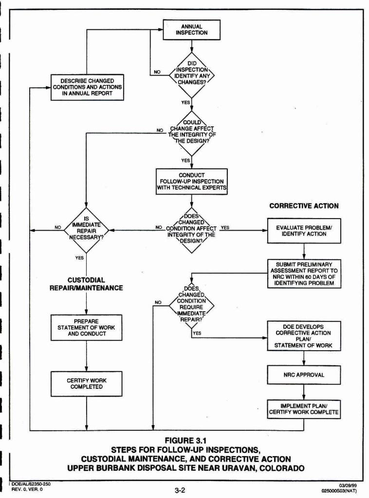
The DOE will inspect the Upper Burbank disposal site to detect progressive change caused by slow-acting natural processes and to identify potential problems before the need for extensive maintenance, repairs, or corrective action. Inspections may also be cunducted to follow up on events or conditions that have affected or potentially could affect the disposal site. The DOE will compare the findings from these inspections to initial baseline conditions to identify changes over time and to provide a basis for future inspections, repairs, and corrective actions. This process is shown in Figure 3.1. Custodial maintenance and repair are described in Section 4.0. Corrective action is detailed in Section 5.0.
INSPECTlON FREQUENCY
The DOE will inspect the Upper Burbank disposal cell annually. The DOE may schedule more frequent inspections if neceesary. The DOE will notrfy the NRC of the Rspection schedule.
INSPECTION TEAM
The inspection team will consist of a minimum of two inspectors qualified to inspect disposal cell integrity and make preliminary assessment$ of modifying processes that could adversely affect the disposal cell.
If problems are observed that require more investigation, follow-up inspections wlll be performed and teams will include one or more technical specialists in appropriate disciplines to assess the problems under investigation. For example, a follow-up inspection by a plant specialist may be required to evaluate reports of significant plant growth on the rock cover, or a wPs scientist or geomorphologist may be needed to evaluate erosion processes.
SITE INSPECTION PROCEDURES
Before Inspections, inspectors will conduct a preinspection briefing. The long-tetm sutveillance program guidance (DOE, 1996a) contains information useful in
'
preparing for inspections.
Site inspections will cover the disposal cell, the surrounding disposal site area, and the immediate offsite areas. Site inspections must be thorough enough to identify any significant changes or active modifying processes that potentially could adverseiy impact the disposal cell. Sunreillance wili be performed to identify the unanticipated effects of modiiing processes such as gully formation, slope erosion, changes to the rock cover, ephemeral drainage channel changes, and significant modifications by humans, animals, or plants.
Inspectors will evaluate the integrity of the disposal cell by walking a series of transects around the perimeter and over the rock cover. Sufficient transects, at approximately 150-ft (46-m) intervals, will be walked to ensure that the disposal mll is thoroughly covered and inspected. Diagonal transem of the topslopes wlll be made and the crest line will be walked. Additional transects will be walked along the sideslopes and rock apron. f ransects along the entire length of the drainage ditch
WEIAU62350-250 OmwSB REV, 0, VER. 0 0250WS03(NAf)
3-1
I I I
c
I I I I I I I I 1 I C I I I
ANNUAL MPECTDON
WGURE 3.1
I STEPS FOR FOLLOW-UP INSPECilONS,
CUSTODIAL MAINTENANCE, AND CORRECllVE ACTION UPPER BURBANK DISPOSAL SITE NEAR URAVAN, COLORADO
I ' 1 wEtNm3mm REV. 0. VER 0
OmBm 3-2 ~swos6at~~v
DESCRIBE CHANGED " Gb","EZ,".>
c CONDmQNS AND ACTlONS IN ANNUAL REPORT K Vr AWGE AFFECT
E INlEGRrrY OF
CONDUCT m w - U P lwecnm
Wlftl TECHNICAL EXPERTS
CORRECTIVE ACTION
IS IMMEDlA /H%?EA " .CONDITION AFFW y m
HECESSAR EVALUATE PROBLEM1
- -3 ~ b a m OF THE \DESIGN?/
IDENTIFY ACT~ON
V
CUSTODIAL
sumrr PREUMINARY ASSESSMEM REPORTTO NAC WmIN DAYS OF
REPAI WINTENANCE IDENTIFYHQ PROBLEM
I PREPARE
STATEMENT OF WORK AND CONDUCT
rn
DOE DEVELOPS WRECTlVE ACTlON
PLANI 7
STATEMENT OF WORK
I
CERTlfY WORK m m o
1 NRc APPROVAL
A
I tM PLEMENT PeAMl
CERTIFY WORKOOPAPLFE
9 1
LOMQ-TERM WRVUUaPK;E PlAN FOR THE UPPER 8UR-K DISPOSAL CELL. UAAVAPI. C[KORA~O SITE IMSPECTIONS
will be made to detemline if it is functioning as designed and cen be expected to continue to function properly, Inspectors wHI make efforts to vary the transect pafhs from one inspection to the next to ensure small anomalies are not overlooked. The sample inspection checktiit in the LTSP guidance document llsts Ibms that should be examined duriw inspections (DOE, 1996a),
The disposal cell has a rock wwer and there Is no planned vegetation on the dispod cell. However, medial action of the amas surrounding the disposal cell included revegetation with grasses. The area sumundmg the disposal cell will be monifomd to determine the success df the revegetation efforts. -Inspectors also will inspect this area for evidenoe of ermim cawed by wind, sheewash, or changes in drainage patterns.
Site inspections also will monitor damage to or disturbance of permanent site surveillance feabres, fencing, gate, and locks.
From inside the disposal site. inspectors will visuqlly sunrey the area approximately 0.25 mi (040 km) outside the dlsposat site boundary for evidence of hnd-use changes that indicate increased human activity such as new roads and paths. lnspecfors will note the ciandir~n d and changes to site access roads, surrounding vegetation, and relevant ge~morphic features ti ke gullies or ephemeral drainage channels. Potential impacts to the site will be noted.
FOLLOW-UP INSPECTIONS
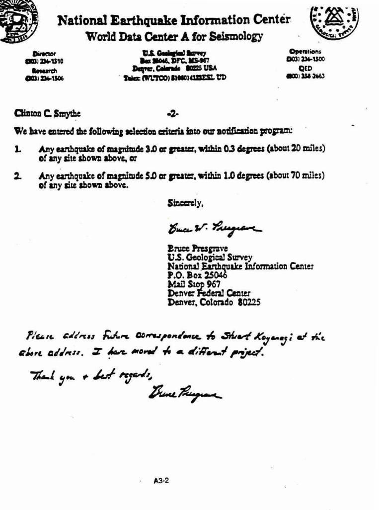
In addition to annual inspections, the DOE may conduct fallow-up inspecbuns due to unusual or annual inspectron findings or observations. DOE may also conduct follow-up inspections to investigak and quantify specific problems found during a previous inspedon, other DOE-initiated activrty, or confirmed repoe of vandalism (intrusion, damage), unusual occurrences, or other significant threat to the disposal site. The DOE will monitor the disposal cell area for the occurrence of extreme natural events (e.g,, earthquakes, tornadoes, floods) and vandalism to ensure such events are investigated in a timely manner to assess their effects Of3 the disposal cell. To facilitate this, the DOE has requested notification from federal, state, and local agencies of discoveries or reports of any purposeful Intrusion or damage at the disposal site as well as in the disposal site area, Notification agreements with the Montrose County SherWs Office and the U.S. Geological Survey National Earthquake Information Center are included in Attachment 3. The DOE will also monitor the weather for the occurrence of severe storms in the disposal ell vicinity. In addiion, the DOE 24-hour telephone number is posted on the site entrance sign so the public can notify the DOE if problems ate discavered. If an extreme natural event or vandalism has occurred, the, DOE will inspect the mil to assess the damage. The notification, response, and follow-up activities will be documented. This documentation will be included in the annual site report to the NRC and become part of the permanent site flle,
'
The nature of the occurrence and the amount of firsthand knwledge available will determine the DOE response, Ha situation poses a threat to the public, the DOE will notify individuals who may be a f f e d and apprupiiate federal, state, and local
DOEIALWrnU-250 0711 3/99 REV. 1. VER. 0 ~ 6 O C X ) ~ ~ ~ ' I ~

LQNQTERM B U R E W E PLAN M 7He UPPER BURWNK MSPWLCELL, LIRAVAN. WRAW SITE IP~SPEET IONS
agencies, including the NRC, II necessary, the DOE will schedule a fdiow-up inspection tp asses any putemal effects fmm the unusual occurrence, and will take necessary rwonse action. Follow~up inspections will be conducted to determine whether processes cumntly active at or near the site threatern site Muriity or stabliii and to evaluate the need for custodial maintenanw, repair, or other corrective mtion. The swpe of these follow-up inspections may be broad and similar in nature to routine she Inspections or facussd on specific areas of mnmrn.
QUAUTY ASSURANCE
The DOE has developed and Implemented a quality assurance (QA) plan (WE, I996a) for the site inspeaion program that m=#s the mquirernents of DOE Order 5700.61;. Site Inspections wlll he conducted in tlcCordance with this QA plan.
L O N ~ T E R M ~ N C E PUN FORTHE UPPER WK pl!Po$M CELL. WAYAN, CoLwihm C W O D W MAW- AND ftEPAlR
4.0 CUSTODIAL MAWENANCE AND REPAIR
The DOE does not plan to conduct routine maintenam at the Upper Burbank disposal site. However, the DOE will perform needed custodlaf maintenance or repair as determined from slte inspections,
Unscheduled custacMl maintenance or repair at the Upper Burbank d ispW slte may include the following:
Repairing or replacing deteriorated or vandalized warning signs, fencing, gate, locks, and monitor well cap&
Removing deep-rooted plants debrmlned to be a threat to the integrity of the covet.
* Reseeding areas surrounding the disposal -If.
After the work is cornpiefed and before the eontractors are released, the DOE will verify that work was performed according to specification. The annual report to the MRC will document repairs that are performed. Copies of records, repork, and Wificatians will be included in the permanent site file.
W ~ 3 5 D . 2 5 0 fmwn9 REV. 0. VER. 0 02-(MA"nl

LOM~-TERM SURvUUAHCE P U N F O A W W P E R W K CW., URAUAN, CrlLORADO CORRfmVE ACTlohl
5.0 CORRECTIVE ACTION
Corrsctive action is M m e d as repairs that are needed to address problems that effect he integrity of the disposal cell or compliance with 40 CFR Part 192. The NRC must approve the recommended action in advance. Site inspectiins are designed to ident'w problems at the developmental stage. Examples of oonditkms thai might trigger corrective action are as follws:
Surfam rmure or subsidence of the d t l cell.
Developmsnt of rllls, gullies, or slope instabilii on the disposal d l .
Deterioration of the erosion-protection rock on the disposal cell,
Tailings fluids migin&infl from the disposal cell.
Gully development on or immediately adjacent to disposal site property that muld affect the integrily of the disposal cell.
r Damage to the cell cover or dhposerl site property from natural catastrophic events or vandalism,
Damage to the disposal cell mver from deep-rooted plant growth.
The DOE will evaluate the factors that caused the problem and identify actions to rnhigate the impact and prevent recurrence. An onshe inspection or preliminary assessment will Include, but is not limited to:
Identifying the nature and extent of the problem. Reevaluating germane engineering design parameters.
For conditjons that warrant a follow-up Inspedion, the DOE will submit a preliminary assessment or status repart ta NRC within 80 days of the inspection. The preliminary assessment report will evaluate the problem and recommend tha next step (e-g., Immediate action or continued evaluation). H the problem requirws immediate repair, the DOE will develop a corrective action plan for NRC apprwal, Once the NRC approves the or)m&ive action, the DOE will implement the plan. In some cases, oorreetivs action could include ternparay emergency measure6 instituted prim to completion af the normal approval process. if.the problem does not requjrs immediate repair, the problem MIl be documented in the annual repott and assessed at the next annual inspeMon.
NRC regulations do not stipulate a time frame for implementing corrective action (except the finding of an sxceedance in estabfiskd ground water concentration limits). The DOE does not consider assessing the extent of a problem and dewlaping e mectlva action plan to be Initiation of the corrective action program.
In addition to the preliminary assessment reporl, the DOE may (as appropriate) prepare a progress repart on each corrmtSve aMon while it is under way or under evaluation.
wwALWp5D3W wm3198 REV. Q VER. 0 o2wwsas E A T l

After corrective U o n is wrmplete, DOE will mfy work and submit a certification dutament and upp porting documentation to the NRC for review and eoncumce. A copy of the ceditication statement will b m e part of the permanent site file, as wlll reports, data, and documentation generated during the cordw action.
DOElm95a-eSo 031[)9198 REV. 0. VER.0 OZswosPs WATl
t D W - ~ S U R V i N C E P U P l TOAYM UPPW8URANK DlBPDs&CEk yFMYAN, GOloRAW RECORD KEEPINO AND mF\THNG
6.0 RECORD KEEPING AND REPORTING
The DOE will maintaln a permanent sib file containing site inspection reports and other supporting documentation af tong-term survejllance program actiWtes. The information plamd In the sfte fiie will include:
DocurneMatian of di-l site performance.
Demonstration that IicensrIng provisions were met.
Information needed to forecast future sit~uw4llance and monitoring needs.
Reports to stakeholders regarding dtpusal cell Integrity.
After the site is brought under the general license, the DOE MlI compile copies of site documentation required by the long-tm suweillance program guidance for the Upper Burbank dkposal slte permanent sha fib (DOE, la90a). Copies of deeds, custody agreements, and other property documents will be kept in the site file.
The DOE wll maintain the suwllhm and maintenance documentation identifted in other sections of this LTSP, and it will bscoms pari of Ithe permahent sii file. The DOE will update the site fite as necessary after dispasal site inspections, maintenance activities, or corrective actions are complete. These records will be handled in mrdance with DOE directives to ensure their proper handling, maintemnce, and disposition. The archival procedures set forth in 41 CFR Part 101 and 36 CfR Pans 122elm (Subehaptw El) will be followed. The permanent site file infatmation will be available for NRC and public review.
During eite inspections, activities and obsewationa will be m r d e d and dewribed usjng site in~pection checklists, maps, photographs and photo lags, and field notes. Documentary evicfence of enmatous, new, or unexpected conditions or situations must describe developing trends and enable the DOE to make decision8 concerning follow-up inspections, custodIsl maintenance, and correcthe action. This Information wll be contained in the permanent site file at the DOE oftice. The DOE will prepare a slts hspecthn report documenting the findings and remmrnendatjons from field Inspeciions.
Site inspecfion reports will be submitted to the NRC within 90 days of the annual stte inspection. Inspection reporb will summarize the results of follow-up inspctjons and maintenance completed h o e the previous annual inspection,
I f unusual damage or disruption is H ivered at the disposal site durh~g an inspection, a preliminary report m j n g the impact must be submitted to the NRC within 80 days. If maintenance, repair, or curredive aetion is warranted, the DUE will notify the MRC. The NRC w311 remive a wpjr of wrectiue action plans and of

W&TEAM FURYEllUNCE PUN FOR nlEuPPER BWUNK DISPOSAL CELL URAYAN, RECORD KEEPING AND REPORTING
each corrective action progress report or the reporta wlll be attached to the annual report.
The DOE Jso will provide copies of inspeaon reports and other r e p k generate4 under the long-term sumillranee program to the at& of Colorado as required in the coapemtive agreement
DWAV8a350-21 o m REV. 0, YfA. 0 Oem[]B(NAT)
6-2

~ m s ~ w m T H E u ~ w m m DrnWSAL CELL !MAYAN, COLORAM REWREMCES
7.0 REFERENCES
DOE (U, S. Department of Energy), tB96a. Guidsnm for lmplementiflg the Long-Term Sutveni~nce Pfogmrn for UMRA Pmject 71tIa I DIspmaI Sites, DOUAL-62350-180, Rev, 0, U.S. Department of Energy, Environmental Restoration D'iision, UMTRA Project Team, Albuquerque, New Mexico.
DOE (U .S. Department of hsrgy), 1896b- Lo~pTetm Surveitlanm and Mahtenance Program, Qua!& Assurance Pmgmm Plan, MAG21 52, Rev, 0, prepared by MACTEC Environmental Restoration Services, for the US. Department of Energy, Grand;lunction Office, Grand Junction, Colorado.
DOE (U.S. Department of Energy), 1995,1896, and 1998. RAP in vati~us confi~umttions . . .. CODE OF f EDERAL REGUlATiDNS
1 0 CFR Part 40, Domestic Licensing of Source Mateal, U.S, Nlrclear Regulatory Commission.
36 CFR Parts 1220-1 238, National Archives and Records, Subchapter B - Records Management, National Archives and Records Administration.
40 CFR Part 1 92, HWfh and Environmental Protection Standads for Uranium and Thorium Mill Tailings, U .S. Environmental Protection Agency.
41 CFR Part 1 01, Federal Property Managemen? Regulations, General S~nrices Administration.
DOE ORDERS
Order SfOOdC, Quality Assurence, 2 1 Augwt 1 991 , U .$. Department of Energy, Washington, D.C.
UNITED STATES CODE
42 USC 57301 et seq,, Uranium MHI Tailings RaaIiation ConW Act of f W8,8 November 1 978.

ATTACHMENT 1
NRC CONCURRENCE DOCUMENTATION

••,cFP REG 0J
UNITED STATES02 NUCLEAR REGULATORY COMMISSIONt WASHINGTON, D.C. 20555-0001
V4* August 25, 1999
Mr. George Rael, DirectorU.S. Department of EnergyEnvironmental Restoration DivisionAlbuquerque Operations OfficeERD/UMTRAP.O. Box 5400Albuquerque, NM 87185-5400
SUBJECT: ACCEPTANCE OF THE LONG-TERM SURVEILLANCE PLAN FOR THENATURITA, COLORADO, URANIUM MILL TAILINGS REMEDIAL ACTIONPROJECT SITE
Dear Mr. Rael:
The U.S. Nuclear Regulatory Commission (NRC) staff hereby accepts the U.S. Department ofEnergy's (DOE's) Long-Term Surveillance Plan (LTSP), dated July 1999, as amended withappropriate replacement page changes, dated July 15, 1999, for the Naturita, Colorado,Uranium Mill Tailings Remedial Action Project site. This action establishes the Naturita siteunder the general license in 10 CFR Part 40.27.
The NRC staff made a determination that all of the previously identified open issues raised inNRC's transmittal dated June 4, 1999, have been adequately addressed in the July 1999version of the LTSP for the Naturita site.
The LTSP satisfies the requirement set forth in the Uranium Mill Tailing Radiation Control Act of1978 for the long-term surveillance of a disposal site, and all requirements in 10 CFR Part40.27 for an LTSP. In accordance with DOE's guidance document for long-term surveillance,all further NRC/DOE interaction on the long-term care for the Naturita site will be conductedwith DOE's Grand Junction Project Office.

G. Rael -2- August 25, 1999
If you have any questions concerning this subject, please contact Mr. Robert Carlson of my staffat (301) 415-8165.
Sincerely,
[D. Gillen for]
John J. Surmeier, ChiefUranium Recovery and
Low-Level Waste BranchDivision of Waste ManagementOffice of Nuclear Material Safety
and Safeguards
cc: W. Woodworth, DOE AIbF. Bosiljevac, DOE AibS. Hamp, DOE AIbE. Artiglia, TAC AIbR. Edge, DOE GRJR. Cornish, DOE AIbJ. Deckler, CDPHE
DISTRIBUTION ,uWa .:CNWRAJLusherJHolonich
RCarlsonWFordCAbrams
NMSS r/fDRomACNWJKennedy
URLL r/fTJohnsonMLayton
BSpitzberg/RIV
DOCUMENT NAME: G:\URLL\RDC\NATURITA LTSP.WPD
SOFC UL RL U
NAME ,•.enJDG JSurmeie%-
DATE 8/,,,2qI1/998 __ 88/.,,9/99-
OFFICIAL RECORD COPY
This documen(iý ýl~de made available to the PUBLIC,. 7 '&,12•1/'?y(Initials) (Date)

ArrACHMENT 2
SITE REAL ESTATE INFORMATION

LIDNPTERM SURVUWEPLAN WR WWPERBWIANK mmw. CELL, mmh, 0010RMK] REAL ESTATE DOCUMEMTATION
REAL ESTATE DOGUMENTATION
The Urenlum Mil Tailings Radiation Control Act [LIMTRCA) of 197'8, as amended, requires the Secretary of Energy to permanently acquim lands needed in carry out the purposes of the UMTRCA. The area the U.S, Department of Energy (DOE) selected for the Naturita dlspmd site was located an p r i m land awned by Umetco Minerals Corporation, a Delaware corporation (Urn-),
ADMINIStRkTIOM OF THE DISPOSAL SITE
The disposal site is located on land formsrty owed by Umstco. Under the requirements of the UIIRTRCA, as amended, the DOE acquired the.dhpsa1 site land da valuable oonsideration. The sale consists of 28.65 acres in accardanm with the terms of the UMTRCA. As o result of the sale, the land is no longer subject to the operation of the general land laws, including the mining and mineral leasing laws. This sale ta the DOE W e d in the DOE the full management, juriddun, responsibility, and liability for the land and all activities conducted thereon.
LEGAL DESCRIPIION
Recordad deed racord8fion Is filed at the wurPty seat of Montmw munty, Cotorado filed: @I 6/1997, at Entnr No. 6B173, Deed Book No, 6945. DO, WD 1 of 1 R 6.00 D 0,OO N 0.00 C W R E C Montrose County. Beginning at a pint which lies swth 85O48'4gU west, 3372.34 feet f ram the northem corner of Section 4, Township 47 North, Range 17 W s t , New Mexica Principal NEsrMan and considering the north line of said Section 4 to bear nnorth 85°47'29" west and all bearings contained herein relative thereto, thence muth 36'1 8'1 2 m, 255.08 feet, more ar less, to the north line of mll dte claim Umwn No. 63 as recorded In the office of the Recorder of Montrwe Caunty, Cobrado; thence north 82'16'49" west along said north line 361 ,?Z feat, fhence south 52O52'58' west, 503.81 bet, thence south 33'25'51" east, 245.53 feet, more ot less, to the north line of hill site claims Urawn No. 66 and 67 as recurded in the office of the Recorder of Montrose County, Colorado; thence north 81 "36'52" wesf along said north Ilne, 134.1 8 feat; thance north 49O16'53" west, 152.74 feet; thence north W58'08" west, 351 .I3 feet; thence north 34'29'1 9" west, 238.62 feet: thence north WQ2W4Q" west, 233.37 feet; thence north 8a028'44* west, 342.58 feet; t h e m north 27'1 3'04- east, 51 521 feet; thence north 28047'5fm east, 202.47 feet; thence north 24"51a27" east, 22023 feet; thence south 61 a 1 607" east, 150.1 6 feet, thence south 48'51 '01" east, 61 1.42 feet thence souh 37027'2T east, 378,02 feet; thence south 36a18'12 east, 308.00 feet to the point of begfnning, containing 26-65 acres.
REPOSITORY
Real estate correspondence and related document3 are maintained and filed by the Property Management Branch, Property and Adrninistpadve Services Division, U. S, Department of Energy Albuquerque Operations Office, P.O. Box 5400, Albuquerque, MM 871 15,505-845-5598,
42 USC 57901 et sleq, , Umnim Mi// TaIIings Radiation Control Act of 1978, 8 November 1 978.
W U ~ m W t m Y REV. 0. Vm 0 Oe50OPA2!WTI
ATTACHMENT 3
AGENCY NOTIFICATION AGREEMENTS

W bPDC
National Evthquskt Monnstion Ctnter World Data CtnttrA far ktmalogr
kna k lo twibm b t the DUE aarad J & u a . h p Wa whom phone I f i n c @ 0 3 ) 2 ( 1 4 D 7 0 h k t a . a d d t s w a o ~ o o k n f o r t k ~ o f I anbpvJru war* lollo* bcrdonr:
Ea=Rtbg=e us. GdogisJ m y Hacjord,E& rlrr Infomatiw b u r P.0. Box 25 d birils 967 b n v a ";Pssenlceaur mv#. C o r d 0 8 W
PLATE 1
LOCATION OF MONUMENTS, MARKERS AND SIGNS

Plates are not available in electronic format. Please e-mail [email protected] to request the plate.