
THIS PAGE INTENTIONALLY LEFT BLANK · eply to attention of: department of the army st. louis...
199
I I I I I I I I I 1 i i i i i i i i i FINAL Five-Year Review Report Initial Five-Year Review Report for i I FUSRAP St. Louis Sites ' St. Louis, Missouri August 23,2004 PREPARED BY U.S. Army Corps of Engineers, St. Louis District Formerly Utilized Sites Remedial Action Program 8945 Latty Avenue Berkeley, MO 63134 ; S4ft£r « ta_ « Approved by: Date: [Name] [Title] [Affiliation] Approved by: Date: [Name] [Title] [Affiliation] 40161807 SUPERFUND RECORDS
Transcript of THIS PAGE INTENTIONALLY LEFT BLANK · eply to attention of: department of the army st. louis...

IIIIIIIII1iiiiiiiii
FINAL
Five-Year Review Report
Initial Five-Year Review Report
for iI
FUSRAP St. Louis Sites '
St. Louis, Missouri
August 23,2004
PREPARED BY
U.S. Army Corps of Engineers, St. Louis DistrictFormerly Utilized Sites Remedial Action Program
8945 Latty AvenueBerkeley, MO 63134
; S4ft£r «
ta_ «
Approved by: Date:
[Name][Title][Affiliation]
Approved by: Date:
[Name][Title][Affiliation]
40161807
SUPERFUND RECORDS

THIS PAGE INTENTIONALLY LEFT BLANK

DEPARTMENT OF THE ARMYST. LOUIS DISTRICT, CORPS OF ENGINEERS
8945 LATTY AVENUEBERKELEY, MISSOURI 63134
EPLY TOATTENTION OF:
September 9, 2004
Formerly Utilized Sites Remedial Action Program
Subject: Draft Final Five-Year Review Report: Initial Report for FUSRAP St. Louis Sites dated August23, 2004
Mr. Dan WallU.S. Environmental Protection AgencyRegion VII, Superfund Branch901 North Fifth StreetKansas City, KS 66101-2907
Dear Mr. Wall:
In accordance with Section X, paragraph B.2 of the Federal Facility Agreement please findenclosed a copy of the draft Final Five-Year Review Report: Initial Report for FUSRAP St. Louis Sitesdated August 23, 2004 for your review. The Federal Facility Agreement allows a thirty (30) day periodfor review of primary documents however should your review allow acceptance prior to the expiration ofthis 30-day period please indicate such by signing and dating the enclosed copy of this letter in the placeindicated and returning it to the above address.
The 30-day Public Review period for the draft report ended on July 28, 2004. The onlycomments received on the Public Review version of the report were received from the MissouriDepartment of Natural Resources (MDNR) via letter dated July 29, 2004. MDNR restated twocomments, made on earlier versions of the report, regarding ground water at the St. Louis Airport Site. Acopy of MDNR's July 29, 2004 letter and the Unites States Army Corps of Engineer's letter reply datedSeptember 9, 2004 are also enclosed for your review.
If you have any concerns or questions regarding this matter, please contact Gerald Allen at (314)263-1543.
Sincerely,
Sharon R. CornerFUSRAP Program Manager
Enclosures
CF: Mr. Robert Geller, Missouri Department of Natural ResourcesMs. Jo Anne Wade, Missouri Dept. of Natural Resources '
Accepted By:tes^nvi)tonme/ntal Protection Agency
Date:


EPLY TOATTENTION OF:
DEPARTMENT OF THE ARMYST. LOUIS DISTRICT, CORPS OF ENGINEERS
8945 LATTY AVENUE nw»enfenBERKELEY, MISSOURI 63134 RECEIVED
SEP, J 5 2004September 9, 2004 SUPEWUND OMSOM
Formerly Utilized Sites Remedial Action Program
Subject: Draft Final Five-Year Review Report: Initial Report for FUSRAP St. Louis Sites dated August23, 2004
Mr. Dan WallU.S. Environmental Protection AgencyRegion VII, Superfund Branch :
901 North Fifth StreetKansas City, KS 66101 -2907
Dear Mr. Wall:
In accordance with Section X, paragraph B.2 of the Federal Facility Agreement please findenclosed a copy of the draft Final Five-Year Review Report: Initial Report for FUSRAP St. Louis Sitesdated August 23, 2004 for your review. The Federal Facility Agreement allows a thirty (30) day periodfor review of primary documents however should your review allow acceptance prior to the expiration ofthis 30-day period please indicate such by signing and dating the enclosed copy of this letter in the placeindicated and returning it to the above address.
The 30-day Public Review period for the draft report ended on July 28, 2004. The onlycomments received on the Public Review version of the report were received from the MissouriDepartment of Natural Resources (MDNR) via letter dated July 29, 2004. MDNR restated twocomments, made on earlier versions of the report, regarding ground water at the St. Louis Airport Site. Acopy of MDNR's July 29, 2004 letter and the Unites States Army Corps of Engineer's letter reply datedSeptember 9, 2004 are also enclosed for your review.
If you have any concerns or questions regarding this matter, please contact Gerald Allen at (314)263-1543.
Sincerely,
Sharon R. CotnerFUSRAP Program Manager
Enclosures
CF: Mr. Robert Geller, Missouri Department of Natural ResourcesMs. Jo Anne Wade, Missouri Dept. of Natural Resources

• prcrn/rnTABLE OF CONTENTS ntvwwci*
• SECTION S£P;J520J4 PAGE
SUPERFUND DIVISION
| LIST OF TABLES ................................................. ........................................................................ ii
• LIST OF FIGURES .................................................. . .................................................................... iii
LIST OF APPENDICES .................................................... : .................................................. . ........ iii
II
ACRONYMS AND ABBREVIATIONS ...................................................................................... iv
EXECUTIVE SUMMARY ....................................................................................................... ES-1
FIVE-YEAR REVIEW SUMMARY FORM .................. '. ........................................................... S-l
I. INTRODUCTION ................................................................................................................. 1-1
II. SITE CHRONOLOGY ........................................................................................................ II-l
• HI. BACKGROUND ................................................................................................................ III-l
• IV. ST. LOUIS SITE RESPONSE ACTIONS ......................................................................... IV-1
V. PROGRESS SINCE THE LAST REVIEW ........................................................................ V-l
I VI. FIVE-YEAR REVIEW PROCESS ............................ . ....................................................... VI-1
VII. TECHNICAL ASSESSMENT .......................................................................................... VIM
VIII. ISSUES .......................................................... . ............................................................ VIII-1
IX. RECOMMENDATIONS AND FOLLOW-UP ACTIONS ............................................... IX-1
X. PROTECTIVENESS STATEMENT .......................... . ....................................................... X-l
I
-
XI. NEXT REVIEW ................................................................................................................. XI-1
I XII. REFERENCES .................................................................................................................. XII- 1
I
I
I
I

LIST OF TABLES
Table ES-1. St. Louis Downtown Site Remedial Action Summary ES-1Table ES-2. SLAPS Removal Action Summary ES-2Table ES-3. HISS and VP-2(L) Removal Action Summary ES-3Table II-1. Chronology of Site Events II-lTable III-l. St. Louis Downtown Site Properties III-4Table III-2. North St. Louis County Site Properties - SLAPS and SLAPS VPs III-l 1Table III-3. North St. Louis County Site Properties - The HISS and HISS/Larty
. VPs HI-13Table III-4. North St. Louis County Site Properties - Coldwater Creek 111-15Table IV-1. St. Louis Downtown Site Remedial Activities Summary IV-6Table F/-2. SLAPS Removal Action Summary IV-18Table IV-3. HISS Stockpiles Removal Summary IV-19Table VI-1. List of Response Action Documents VI-2Table VI-2. List of Implementation Documents VI-3Table VI-3. List of Response Action Evaluation Documents VI-4Table VI-4. Revised Background Values for the North St. Louis County Sites
HZ-C/HZ-E Hydrostratigraphic Zones VI-8Table VI-5. Summary of Wastewater Discharges at the SLDS VI-29Table VI-6. External Gamma Radiation Monitoring Results at the SLDS VI-35Table VI-7. External Gamma Dose Rate at the SLDS VI-35Table VI-8. Air Paniculate Monitoring at the SLDS VI-36Table VI-9. Airborne Paniculate Dose Rate at the SLDS VI-37Table VI-10. Radon Monitoring at the SLDS VI-38Table VI-11. Radon Concentration and Dose Rate at the SLDS VI-38Table VI-12. External Gamma Radiation Monitoring at the SLAPS VI-40Table VI-13. External Gamma Dose Rate at the SLAPS VI-40Table VI-14. Air Paniculate Monitoring at the SLAPS Vl-41Table VI-15. Airborne Particulate Dose Rate at the SLAPS VI-42Table VI-16. Radon Monitoring at the SLAPS VI-42Table VI-17. Radon Concentration and Dose Rates at the SLAPS VI-43Table VI-18. External Gamma Radiation Monitoring at the HISS VI-45Table VI-19. External Gamma Dose Rate at the HISS VI-45Table VI-20. Air Particulate Monitoring at the HISS VI-46Table VI-21. Airborne Particulate Dose Rate at the HISS VI-47Table VI-22. Radon Monitoring at the HISS VMSTable VI-23. Radon Concentration and Dose Rate at the HISS VI-48Table VI-24. Radon Release Rate at the HISS VI-49Table VI-25. SLS Confirmatory Soil Sampling Program Completed Actions VI-50Table VII-1. Changes in Standards and Investigative Limits VII-3Table VIII-1. SLDS Issue VIII-1Table VIII-2. North St. Louis County Sites Issue Vffl-2
11

IIIIIiiiiiiiiiiiiii
LIST OF FIGURES
Figure III-l. Location Map of the St. Louis Sites III-2Figure III-2. Plan View of the SLDS : . III-3Figure III-3. Generalized Stratigraphic Columns for the SLDS III-5Figure III-4. North St. Louis County Site Map III-9Figure III-5. Location of Hazelwood Interm Storage Site (HISS) HI-10Figure III-6. Generalized Stratigraphic Column for the SLAPS and the HISS III-l8Figure IV-1. St. Louis Airport Site F/-17Figure VI-1. Ground-water Monitoring Well Locations at the HISS in CY 2002 VI-12Figure VI-2. Trend Analysis at the HISS VI-13Figure VI-3. Ground-water Monitoring Well Locations at the SLAPS in CY 2002 VI-18Figure Vl-4. Trend Analysis at the SLAPS-Arsenic VI-21Figure VI-5. Trend Analysis at the SLAPS-Selenium VI-23Figure VI-6. Trend Analysis at the SLAPS-Total Uranium ..VI-25Figure VI-7. Trend Analysis at the SLAPS-Trichloroethene VI-26Figure VI-8. Ground-water Monitoring Well Locations at the SLDS in CY 2002 VI-28Figure VI-9. Trend Analysis at the SLDS VI-30Figure VI-10. Trend Analysis for Wells Exceeding Investigative Limits at the SLDS ... VI-31Figure VI-11. Trend Analysis for Radionuclides in Coldwater Creek Surface Water VI-55Figure VI-12. Trend Analysis for Radionuclides in Coldwater Creek Sediment VI-56
LIST OF APPENDICES
APPENDIX A - LIST OF DOCUMENTS REVIEWEDAPPENDIX B - SUMMARIES OF DOCUMENTS REVIEWEDAPPENDIX C - SITE INSPECTION REPORTS
111

ACRONYMS AND ABBREVIATIONS
uCi/mL"g/LuL/L/hrAcADMAECARARAsAIDAWQCbgsCdCERCLACFRCicmcm/scocCSRC-TCWPCYDCEDCGLDDEDOEEDEEE/CAEMDARFFAFSFSSFUSRAPFYgalGIFREHCGRAAAHISSHUHZIAILin.ITK-PadLTS
microcuries per millilitermicrograms per litermicroliters per liter per houractiniumArcher Daniels MidlandAtomic Energy Commissionapplicable or relevant and appropriate requirementarsenicalpha track detectorambient water quality criteriabelow ground surfacecadmiumComprehensive Environmental Response, Compensation, and Liability ActCode of Federal Regulationscuriescentimetercentimeter/secondcontaminant of concernCode of State Regulationscolumbium and tantalumConstruction Work Plancalendar yeardichloroetheneDerived Concentration Guideline Limitdeep dose equivalentU.S. Department of Energyeffective dose equivalentengineering evaluation/cost analysisEnvironmental Monitoring Data and Analysis ReportFederal Facility Agreementfeasibility studyFinal Status SurveyFormerly Utilized Sites Remedial Action Programfiscal yeargallon(s)General Investment Funds Real Estate Holding CompanyGround-Water Remedial Action Alternative AssessmentHazelwood Interim Storage Sitehydrostratigraphic unithydrostratigraphic zoneinvestigation areainvestigative limitinch(es)IT CorporationBuilding K foundationlong-term stewardship
IV

IIIIIIIIiiiiiiiiiii
ACRONYMS AND ABBREVIATIONS (Cont'd)
MARSSIM Multi-Agency Radiation Survey and Site Investigation ManualMCL maximum contaminant levelMDNR Missouri Department of Natural ResourcesMED Manhattan Engineer Districtm2 square metermg/kg milligrams per kilogrammg/L milligrams per literMI Mallinckrodt, Inc.MOU Memorandum of Understandingmrem/hr millirem per hourmrem/yr millirem per yearMSD Metropolitan St. Louis Sewer DistrictNCP National Oil and Hazardous Substances Pollution Contingency PlanND non-detectNESHAP National Emission Standards for Hazardous Air PollutantsNPDES National Pollutant Discharge Elimination SystemNPL National Priorities ListNRC Nuclear Regulatory CommissionO&M operations and maintenanceORNL Oak Ridge National LaboratoryOU operable unitpCi/g picocuries per grampCi/L picocuries per literpCi/m2/s picocuries per square meter per secondPRO preliminary remediation goalRa RadiumRAO Remedial action objectiveRAWP Removal Action Work PlanRCRA Resource Conservation and Recovery ActRFI RCRA Facility InvestigationRG Remediation GoalRI remedial investigationRn RadonROD record of decisionROW right-of-waySAIC Science Applications International CorporationSARA Superfund Amendments and Reauthorization Act of 1986SLAPS St. Louis Airport SiteSLDS St. Louis Downtown SiteSLS St. Louis SitesSMCL secondary maximum contaminant levelSOR sum of ratiosSU survey unitTCE TrichloroetheneTEDE total effective dose equivalent

ACRONYMS AND ABBREVIATIONS (Cont'd)
Th ThoriumTLD thermoluminescent dosimeterU UraniumUSAGE U.S. Army Corps of EngineersUSEPA U.S. Environmental Protection AgencyVP vicinity propertyyd3 cubic yard
VI

IIIIIIIIiiiiiiiliii
EXECUTIVE SUMMARY
As the lead agency for the Formerly Utilized Sites Remedial Action Program (FUSRAP)St. Louis Sites (SLS), the U. S. Army Corps of Engineers, St. Louis District (USAGE) conducteda five-year review of the response actions conducted at the SLS pursuant to Section 121 of theComprehensive Environmental Response, Compensation and Liability Act (CERCLA), asamended by the Superfund Amendments and Reauthorization Act of 1986, and to the NationalOil and Hazardous Substances Pollution Contingency Plan (NCP). USAGE is conducting theseresponse actions pursuant to CERCLA and the NCP under the legislative authority contained inthe Energy and Water Development Appropriations Act for Fiscal Year 2000 (FYOO), PublicLaw 106-60, §611 (HR 2605).
The SLS consists of two locations designated as the St. Louis Downtown Site (SLDS) and theNorth St. Louis County sites that contain radiological contamination resulting from previousManhattan Engineering District/Atomic Energy Commission (MED/AEC) operations. Thetriggering action for the five-year review was September 8, 1998, the day when field operationsfor the remedial actions at the SLDS began.
The SLDS is comprised of the Mallinckrodt, Inc. (MI) property and the 34 surrounding vicinityproperties. This site is located near the Mississippi River, north of downtown St. Louis,Missouri. The selected remedy presented in the 1998 SLDS Record of Decision (ROD) requiresthe excavation and disposal of radiological and chemical contamination in surface andsubsurface accessible soil resulting from MED/AEC processing activities. The selected remedyalso includes monitoring of the Mississippi Alluvial Aquifer.
The following table lists the SLDS remedial action covered by the period of this report(September 1998 through August 2003):
Table ES-1. St. Louis Downtown Site Remedial Action Summary
Loc.DT-2MIMIDT-7MIDT-6MI
PropertyCity Property Vicinity PropertyPlant 2Plant 1Midwest Waste Vicinity PropertyPlant 6 East Half (EH) and East (E)Heintz Steel Vicinity PropertyPlant IE
StartOctober 1998October 1998July 2000May 2001November 2000April 2003July 2003
CompleteJuly 1999August 2000March 2002February 2003July 2003In ProgressIn ProgressTotal Volume =
CY Removed4,2609,6602,4903,91018,8801,6601,775
42,635
CY = cubic yards (In-Situ)
Although no soil was remediated at the Archer Daniels Midland (ADM) Vicinity Property (VP)(DT-1), a final status survey was performed that indicated the residual radioactivity was belowthe SLDS ROD remediation goals. Based on this finding, the property was released withoutradiological restrictions.
For the SLDS, a Ground-Water Remedial Action Alternative Assessment (GRAAA) wasinitiated because concentrations of arsenic and uranium in ground-water samples collected fromthe Mississippi Alluvial Aquifer exceeded investigative limits (ILs) established in the SLDS
ES-1

ROD. The conclusion of Phase 1 of the GRAAA (assessment) was that Phase 2 of the GRAAA(investigation) should be conducted (USAGE 2003a).
The North St. Louis County sites are located near the Lambert-St. Louis International Airport inSt. Louis County, Missouri and are composed of the following properties:
• St. Louis Airport Site (SLAPS);
• Latty Avenue Properties, including the Hazelwood Interim Storage Site and Futura Coatings(HISS/Futura), and eight vicinity properties; and
• SLAPS VPs, consisting of approximately 78 properties between the SLAPS, the HISS,Coldwater Creek and the properties along Coldwater Creek.
Several removal actions have been implemented at the North Si. Louis County sites. Theseremoval actions were evaluated in Engineering Evaluation/Cost Analyses (EE/CA) documentsand subsequently were authorized by Action Memoranda. Removal actions at the SLAPS wereevaluated and authorized in accordance with the following EE/CAs and Action Memoranda:
• St. Louis Airport Site (SLAPS) Interim Action Engineering Evaluation/Cost Analysis (EE/CA)and SLAPS Action Memorandum for the Removal of Radioactively Contaminated Material(DOE1997aandl997b).
• Engineering Evaluation/Cost Analysis (EE/CA) and Responsiveness Summary for the St.Louis Airport Site (SLAPS) and Action Memorandum (USAGE 1999a).
The following table summarizes the removal actions conducted at the SLAPS:
Table ES-2. SLAPS Removal Action Summary
DesignationWest End - Sedimentation BasinEast EndRadium PitsPhase 1Phases 2 and 3
StartSeptember 1998October 1998March 2000December 2001December 2002
CompleteMay 1999May 2003October 2000May 2003In ProgressTotal Volume =
CV Removed10,53065,12036,91074,67024,630
211,860CY = cubic yards (In-Situ)
Removal actions for the SLAPS VPs were evaluated in the Engineering Evaluation/CostAnalysis-Environmental Assessment for the Proposed Decontamination of Properties in theVicinity of the Hazelwood Interim Storage Site (DOE 1992), and approved in a subsequentAction Memorandum (DOE 1995).
The removal action at the HISS was evaluated in the Engineering Evaluation/Cost Analysis(EE/CA) for the Hazelwood Interim Storage Site (HISS) (USAGE 1998a), and approved in theAction Memorandum (USAGE 1998b). A major accomplishment during the reporting period(September 1998 through August 2003) was the removal of the waste material stockpiled at theHISS and VP-2(L), as summarized in the following table:
ES-2

IIIIIIIIiiIiiiiIiii
Table ES-3. HISS and VP-2(L) Removal Action Summary
Stockpile DesignationEast Piles 1 and 2Railroad Spur Spoil Piles A and BSupplemental PileMain Pile - Northern PortionMain Pile - Phase 1 - South HalfMain Pile - Phase 2 - North Half
StartApril 2000March 2000September 2000November 2000March 2001September 2001
CompleteJune 2000June 2000October 2000January 2001May 2001October 2001Total Volume =
CY Removed6,8805,5904,7104,44011,9505,905
39,475
CY = cubic yards
This five-year review comes at a time when site response actions are being implemented andconstruction is ongoing. This review, therefore, is not typical of the reviews that will beconducted over the long-term management period. The typical long-term management five-yearreview process is designed to examine remedies that are in place. In the future, after constructioncompletion, five-year review reports will examine land use, institutional control monitoring andenforcement, long-term monitoring, and other long-term management activities.
The assessment of this five-year review determined that the remedial action implemented at theSLDS is in accordance with the requirements of the SLDS ROD. Likewise, this five-year reviewfound that the North St. Louis County sites removal actions are being conducted in accordancewith applicable Action Memoranda.
The response actions implemented to date at the SLDS and the North St. Louis County sites arefunctioning as designed and have been found to be protective of human health and theenvironment. In the interim, exposure pathways that could result in unacceptable risks are beingcontrolled.
ES-3

THIS PAGE INTENTIONALLY LEFT BLANK
m
ES-4

III1IIIIIIIIIIIIIII
Five-Year Review Summary FormSITE IDENT1FICA TION
Site name: Formerly Utilized Sites Remedial Action Program (FUSRAP) - St. Louis Sites (SLS)
EPA ID: MOD980633176
Region: VII State: MO City/County: St. Louis
SITE STATUS
NPL status: SLAPS, HISS and Futura Coatings (HISS/Futura)
Remediation status: Operating at the SLDS. Removal operations ongoing at North St. LouisCounty sites.
Multiple OUs? YES Construction completion date: Not applicable
Has site been put into reuse?The SLDS, Futura Coatings, and various Latty Avenue properties and the SLAPS VPs havefunctioning businesses. The City Property Vicinity Property (DT-2) and Mallinckrodt (MI) Plant 2have been returned to their respective owners for reuse.
REVIEW STATUS
Lead agency: U.S. Army Corps of Engineers (USAGE)
Author name: USAGE, St. Louis District Office (USAGE)
Author title: USAGE, St. Louis District Office Author affiliation: USAGE, St. Louis District
Review period: 09/08/1998 to 08/31/03
Date(s) of site inspection:North St. Louis County sites: April 8-10, 2003SLDS: May 8-9, 2003Type of review:SLDS-Starutory: The five-year review of the Accessible Soil and Ground-Water OU of the SLDS isbeing conducted pursuant to statute because the remedial action at this OU is a post-SARA remedialaction that, when complete, will leave hazardous substances, pollutants, or contaminants on-siteabove levels that allow for unlimited use and unrestricted exposure.
North St. Louis County sites (SLAPS. HISS/Lattv. SLAPS VPs') - Policy: The five-year review ofthe North St. Louis County sites is being conducted as a matter of USEPA policy because a removalaction is taking place at a site that is on the National Priorities List.
Review number: 1 (first)
Triggering action: Commencement of USAGE field operations at the SLDS.
Triggering action date: 09/08/1998
Due date (five years after triggering action date): 09/08/2003
Note: "OU" refers to operable unit.
S-l

Five-Year Review Summary Form (Cont'd.)
Issues:
St. Louis Downtown Site
Residual radioactivity concentrations in the St. Louis Downtown Site (SLDS) inaccessible soil:Radionuclides may remain in the SLDS inaccessible soil at concentrations above levels that allow forunlimited use and unrestricted exposure. USAGE is currently developing the ComprehensiveEnvironmental Response, Compensation, and Liability Act (CERCLA) documentation necessary toaddress inaccessible soil at the SLDS. A Long-Term Stewardship Plan will be prepared to documentprocesses and procedures with respect to requirements under CERCLA.
North St. Louis County Sites
Thin cover material at the Hazelwood Interim Storage Site (HISS): The cover material (soil) at the HISSis seeded several times per year; however, site drainage patterns appear to be impeding the establishmentof vegetative cover. Thin vegetative cover could result in erosion of the soil cover by surface water andwind. However, even with total loss of the soil cover, the rock and protective geofrabric under the soilcover would prevent further erosion at the HISS.
Recommendations and Follow-Up Actions:
St. Louis Downtown Site
USAGE is currently developing the CERCLA documentation necessary to address inaccessible soil at theSLDS. A Long-Term Stewardship Plan will be prepared to document processes and procedures withrespect to requirements under CERCLA.
North St. Louis County Sites
USAGE will continue to monitor the site to ensure that erosion does not result in an off-site discharge.Any area that is determined by USAGE to be impacted by erosion will be covered (e.g., seeded, crushedrock, geomembrane, clean soil) to prevent migration. USAGE continues efforts to establish vegetation asa means of preventing erosion of the soil cover by surface water and wind.
S-2
IIIIIIIIIIIIIIIIIII

IIIIIIIIIIIIIIIIIII
Five-Year Review Summary Form (Cont'd.)
Protectiveness Statement(s):
St. Louis Downtown Site
The remedy being implemented at the SLDS Operable unit is expected to be protective of human healthand the environment upon attainment of the cleanup goals established in the ROD. In the interim,exposures that could result in unacceptable risks are being controlled through access controls and workplace management practices. Some areas with soil contamination deeper than four feet and some areaswith contamination under permanent structures will be managed in place using institutional controls tolimit use. Long-term ground-water monitoring is being used to confirm that the remedy is protective ofthe alluvial aquifer.
North St. Louis County Sites
The removal actions being implemented at the North St. Louis County sites operable unit are expected tobe protective of human health and the environment upon attainment of the soil cleanup goals establishedin the EE/CAs. In the interim, exposures that could result in unacceptable risks are being controlledthrough access controls, surveillances and maintenance, and coordination with property owners and utilitycompanies. In May 2003, the USAGE published a Proposed Plan for remedial action designed to addressall remaining contamination at the North St. Louis County Sites. Public comment has been received. AROD is currently under development and will be made available upon finalization.
S-3

ii mrfi
S.V
•i
TfflS PAGE INTENTIONALLY LEFT BLANK
S-4

IIIIIIIIIIIIIIIIIII
I. INTRODUCTION
A five-year review was conducted for the Formerly Utilized Sites Remedial Action Program(FUSRAP) St. Louis Sites (SLS). This five-year review comes at a time when site responseactions are being implemented and construction is ongoing. This review, therefore, is not typicalof the reviews that will be conducted over the long-term management period. The typical long-term management five-year review process is designed to examine remedies that are in place. Inthe future, after construction completion, five-year review reports will examine land use,institutional control monitoring and enforcement, long-term monitoring, and other long-termactivities.
The SLS are composed of two locations designated as the St. Louis Downtown Site (SLDS) andthe North St. Louis County sites. The five-year period covered by this review is from September1998 through August 2003. The methods, findings, recommendations, and conclusions of thefive-year review are documented in this five-year review report. This is the first five-year reviewconducted for the FUSPvAP St. Louis Sites.
As the lead agency for the St. Louis Sites, the U. S. Army Corps of Engineers, St. Louis District(USAGE) prepared this five-year review report pursuant to Section 121 of the ComprehensiveEnvironmental Response, Compensation, and Liability Act (CERCLA §121), as amended by theSuperfund Amendments and Reauthorization Act of 1986 (SARA) and to the National Oil andHazardous Substances Pollution Contingency Plan, more commonly called the NationalContingency Plan (NCP). CERCLA §121 (c) states the following:
If the President selects a remedial action that results in any hazardoussubstances, pollutants, or contaminants remaining at the site, the President shallreview such remedial action no less often than each five years after the initiationof such remedial action to assure that human health and the environment arebeing protected by the remedial action being implemented. In addition, if uponsuch review it is the judgment of the President that action is appropriate at suchsite in accordance with section [104] or [106], the President shall take or requiresuch action. The President shall report to the Congress a list of facilities forwhich such review is required, the results of all such reviews, and any actionstaken as a result of such reviews.
The U.S. Environmental Protection Agency (USEPA) interpreted this requirement further in theNCP at 40 Code of Federal Regulations (CFR) 300 [specifically 40 CFR 300.430(f)(4)(ii)], whichstates the following:
If a remedial action is selected that results in hazardous substances, pollutants, orcontaminants remaining at the site above levels that allow for unlimited use andunrestricted exposure, the lead agency shall review such action no less often thanevery five years after the initiation of the selected remedial action.
The USAGE conducted a five-year review of the response actions implemented at the AccessibleSoil and Ground-Water Operable Unit (OU) of the SLDS and the North St. Louis County sites inSt. Louis, Missouri. This review was conducted from January 2003 through August 2003 andcovers the period from September 1998 through August 2003. The results of the review aredocumented in this report. USAGE was assisted in the five-year review by the following entities:USEPA Region VII and the Missouri Department of .Natural Resources (MDNR). USEPA_ _

Region VII and MDNR provided comments and suggestions on the analyses presented in thisfive-year review report.
From April 8 to 10, 2003, site inspections were conducted by USAGE at the North St. LouisCounty sites as part of the five-year review. The following individuals participated in the siteinspection: J. Mattingly, USAGE; S. Roberts, USAGE; D. Wall, USEPA Region VII; and J.Groboski, MDNR.
On May 8 and 9, 2003, a site inspection was conducted by USAGE at the SLDS as part of thefive-year review. The following individuals participated in the site inspection: J. Mattingly,USAGE; G. Allen, USAGE; D. Wall, USEPA Region VII; and J. Wade, MDNR.
This is the first five-year review for the SLS. As stated previously, this five-year reviewaddresses the remedial action conducted at the SLDS Accessible Soil and Ground-Water OU andremoval actions conducted at the North St. Louis County sites. The trigger date for the five-yearreview is September 8, 1998, the day when field operations for the remedial action at the SLDSbegan. The five-year review of the Accessible Soil and Ground-Water OU of the SLDS is beingconducted pursuant to statute because the remedial action at this OU is a post-SARA remedialaction that, when complete, will leave hazardous substances, pollutants, or contaminants on-siteabove levels that allow for unlimited use and unrestricted exposure.
There is yet no triggering action for the other OU at the SLDS, the Inaccessible Soil OU. Thebuildings and inaccessible soil that comprise the Inaccessible Soil OU will be addressed under afuture CERCLA action. USAGE is currently developing the approach to issue a Record ofDecision (ROD) for the Inaccessible Soil OU. The Inaccessible Soil ROD for the SLDS has notyet been completed. EPA and MDNR will be invited to participate in this process. As of August2003, only removal actions have taken place at the North St. Louis County sites. The five-yearreview of the North St. Louis County sites is being conducted as a matter of USEPA policybecause a removal action is taking place at a site that is on the National Priorities List (NPL) [theSt. Louis Airport Site (SLAPS) and the Hazelwood Interim Storage Site (HISS) and FuturaCoatings], Thus far, no remedial action has taken place at the North St. Louis County sites.
1-2

II. SITE CHRONOLOGY
A summary of the SLS chronology of site events is presented in Table II-1 below,highlighted events are applicable to the review period of this report.
Table IM. Chronology of Site Events
The
SITESLDS
North County
SLDSSLDSSLDS
North County
North County
North CountyNorth County
North County
SLDS
North County
North County
North County
North CountySLS
SLDS
North County
SLDSSLDS
SLDS
SLDS
EVENTMI Chemical Works performed work under contract to the Manhattan EngineerDistrict/Atomic Energy Commission (MED/AEC).SLAPS: Acquired by MED/AEC to store uranium-bearing residues and scrap fromthe SLDS.MI Plants 1 and 2: Decontaminated to meet AEC criteria then in effect.Plants 1 and 2: AEC released for use without radiological restrictions.AEC managed decontamination efforts in MI Plants 10, 7, and 6E to meet criteriathen in effect; plants returned to MI for use without radiological restrictions.Continental Mining and Milling Company of Chicago, Illinois, purchased and beganmoving wastes from the SLAPS to the HISS.HISS: Used to store radioactive material purchased from the AEC prior to shipmentto Colorado.SLAPS: Ownership transferred from MED/AEC to St. Louis Airport Authority.HISS: Radiological surveys conducted by the Nuclear Regulatory Commission(NRC) indicated the presence of residual uranium and thorium (Th) concentrationsin the soil above guidelines for unrestricted use of land areas.SLAPS: The U.S. Department of Energy (DOE) performed a radiological survey andfound elevated radionuclide levels on-site and north of the site in ditches north andsouth of McDonnell Boulevard.Radiological survey conducted by Oak Ridge National Laboratory (ORNL) foundalpha and radiological levels in excess of guidelines for release of the property foruse without radiological restrictions (ORNL 1981).HISS: Contaminated soil from the adjacent Futura parcel stockpiled on the HISS insupport of construction of a manufacturing facility.HISS: DOE performed response actions including clearing, excavating, andstockpiling contaminated soil from excavation of the property at 9200 Latty Avenue.HISS: Supplemental pile is created as the result of DOE radiological monitoringsupport of Latty Avenue drainage and street improvements.NPL: USEPA placed the SLAPS, HISS, and Futura properties on the NPL.USEPA, Region VII, and DOE entered into a Federal Facility Agreement (FFA).DOE issued Engineering Evaluation/Cost Analysis for Decontamination of the
St. Louis Downtown Site, St. Louis, MO, DOE/OR/2370 1-02.2, May 1991 (DOE1991).DOE issued Engineering Evaluation/Cost Analysis for the Proposed
Decontamination of the Properties In the Vicinity of the Hazelwood Interim StorageSite, Hazelwood, Missouri, DOE/EA/0489, Rev. 1, March 1992 (DOE 1992).DOE submitted the Remedial Investigation (RI) report for the St. Louis Site.nterim action at MI: 50 Series Buildings - decontamination, demolition, and
crushing pursuant to DOE 1 99 1 .nterim action at MI: Plants 6 and 7- decontamination, asbestos abatement,
demolition to floor elevation grade, and crushing, pursuant to DOE 1991.nterim action at MI: Plant 10 area - subsurface soil excavation and off-site shipment
pursuant to DOE 1991.
DATE1942-1957
1946
1948-195019511962
1966
1966-1973
19731976
1976and19781977
1979
1984
1986
Oct. 4, 1989June 1990May 1991
March 1992
19921996
1997
1997
II-1

Table II-l. Chronology of Site Events (Cont'd)
SITESLDS
North County
North County
SLSNorth CountyNorth County
SLDS
: . • - ' SLDS>'-:-INorth County
: North CountyNorth County"Nbrth'Gounty
SLDSk • • • •> . SLDS . . ' , .'North County
/;•>':'•'. '/"-••.':"?:- .•"'•.
- North County
North County •'•. • .. , . t"
, ^•SLps :,/;; North County.North County
Nortli County. North CountyNorth County;.
••'-VSLDST--.•••.SLDS". '•-
•••'•-.SLDS1-"North 'Comity:.North 'County
;SLDS '.North. County:
• • v > SLDS-,..." •' i " •' .- ' '• ' '-'v'
; SLDS -'.:'
EVENTInterim action at City Property Vicinity Property (VP): Riverfront Trail area -excavation and off-site shipment pursuant to DOE 1991.DOE issued Interim Action Engineering Evaluation/Cost Analysis (EE/CA) for the St.Louis Airport Site (SLAPS), DOE/OR/2 1950- 1026, September 1997 (DOE 1997a).Removal action at the SLAPS: West End — excavation and removal of contaminatedsoil east of Coldwater Creek bank gabion wall on the SLAPS pursuant to DOE 1997.FUSRAP responsibility transferred from DOE to the USACE.SLAPS VP-56: Removal action completed.SLAPS: Construction of a loadout facility and 1200 feet rail spur.SLDS ROD signed by U.S. Army 'Director of Civil Works and by the RegionalAdministrator of USEPA, Region 7.;USACE commenced field operations~at the SLDS.-H ~: r- .USAGE' issued Engineering 'Evaluation/Cost Analysis. (EE/CA) fox. the HazebvaodInte'rim Storage Site (HISS),. October; 1998 (USAGE 1998a). '.'•' . __•SLAPS:: VP Sfe Denis Street' Bridge replacement-support, Florissant, Md • •SLAPS:: North Ditch Rernoval Action and Sedimentation Basin Installation.Latty.Avehue Properties: Rail spur" constructed at the HISS.:.City Property VP: Remedial action .initiated and completed. iMl Plant 2: Remedial action initiated arid. completed;, v 'T
USAGE issued 'Engineering 'Evaluation/Cost 'Analysis- (EE/CA) and ResponsivenessSummary -for the- St. Louis 'Airport Site (SLAPS^an'd Action Memorandum), Marchlv9^9::(U§ACE.;i999a).:;.v"l....:.:^..- --"•> •:' ;'Jf^,.'., • ' . . - . ' . ' . ',-.-. - -
-SLAPS-:-- East End, East. End Extension, an'd Right-bf-Way (ROW) Work Areas -
SLAPS -VPs: Removal action conducted in the North Ditclvarea between McDonnellBouleyard and the. former ballneld arear .7- . . ' ; ; : • * * l •• -."'
Cufrent.SLDS-Remedial Action Work Plan, Revisibft 1 issued.
SLAPS: Egst End and ROW. Work Areas - removal action initiated and- completed.SLAPrS:;Cufrent Site Wide Removal Action Work Plan, Addendum-! to Revision 0issuedV.-"'. I ' - '" '?-"; ' ' " • : ' • " ' : • ' • - . "..•.:-.-" :•'--.•.• -.::''' ' ' . , - " . •SILAPSt'-Radiufn JPits Work"ATea-rerhp.val aetion'iriitiated'and'compjetedi "SLAPS VP::VP-38"Rempval action initiated ariapartially completed.Latty Avenue' Properties: HISS and Future stockpiled material removed and shippedout.of-state:to disposal facilities. . ,,r . : •Vn Plant '-If Remedial action; initiated and.c6mpleted..v -vn-P]arit6E'and6EH: Remedial-action initiated and completedi — • - •Midwest. Waste .VP-: Remedial action initiated and completed.SLAPSfPhase T Work Area ^removal action iriitiated and completed. •SLAPS; Phases 2 and 3 Work Area - removal aciio'n initiated and in progress.Heintz Steel. VP:-Remedial' action initiated and m pfogfess. ' ' • " - • 'feasibility .Study^and. Proposed P.lah for.the..,S,tfLoiijs. North County Site issued(USAGE 20Q3b;cT. '•.-:'"" ••'• ~'' -'. '\ '' .. .' ' :- 'ffiase-1 Grburid^Water Remedial Action Alternative^Assessment .(GRAAA) at theSIOS issued (USAGE" 2003a). ' :' ^ -. ,.:.5: r
vQ Plant 7E: Remedial action initiated and in pxogress""-. • • " * • . ; • - . • • _ . , - - " - . . .
DATE1997
September19971997
Oct. 13, 199719981998
August 1998
Sept 8, 1998October 199S
1998 *1998-19991998^-19991998-1999 11998-2002 1Mareh 1999 •
1999-2001
1999
Dec. 1999
1999-2001.March 2000
20002000
2000-2001
2000-2002)2000-20032001-20032001 -2003
Dec. 2002'April 2003
May 2003
June.2003
July 2003-
II-2

IIIIIIIIIIIIIIIIIII
III. BACKGROUND
Background information on each of the SLS is presented hereafter by site. The locations of theSLS in relation to each other and the City of St. Louis are shown on Figure III-l.
ST. LOUIS DOWNTOWN SITE
The Mallinckrodt, Inc. plants and Vicinity Properties (VPs) that comprise the SLDS are shownon Figure III-2 and are listed in Table III-l. The VPs are also listed according to their associatedUSAGE property designation number (e.g., DT-1). It should be noted that as new data wereobtained and new civil land survey information became available during the ongoing pre-designinvestigation efforts, the size, designation, and number of VPs have increased subsequent tosignature of the SLDS ROD (USAGE 1998c). Such information indicated that certain propertyboundaries and, in some cases, the associated property owners, were incorrect when originallyidentified. The property boundaries shown on Figure III-2 reflect the current understanding ofthe SLDS property boundaries. The SLDS is defined in the SLDS ROD (USAGE 1998c) asconsisting of the Mallinckrodt, Inc. Property and the VPs.
The final remedial action for the accessible soil and ground-water operable unit contaminated asthe result of MED/AEG uranium manufacturing and processing activities at the SLDS isdiscussed in detail in the SLDS ROD. As agreed to under the FFA, hazardous wastes resultingfrom releases on the site during the Mallinckrodt, Inc. operations for the MED/AEG are thesubject of the remedial action at the SLDS. The SLDS has been separated into two OUs: (1) theAccessible Soil and Ground-Water OU and (2) the Inaccessible Soil OU. The Accessible Soiland Ground-Water OU consists of the accessible soil and ground water contaminated as theresult of MED/AEG uranium processing activities at the Mallinckrodt, Inc. plant. TheInaccessible OU consists of buildings within the site perimeter (including Buildings 25 and 101on the Mallinckrodt Property) and contaminated soil that is currently inaccessible due to thepresence of buildings, active rail lines, roadways, the levee, and other permanent structures. TheInaccessible Soil OU was excluded from the scope of the SLDS ROD (USAGE 1998c) becausethe inaccessible soil did not present a significant threat in its current configuration and becauseactivities critical to the continued operation of Mallinckrodt, Inc. prevented excavation beneaththe encumbrances (e.g., roads, active railroads, Buildings 25 and 101). Contamination presentwithin Building 25 also did not present an excessive risk under its current configuration. Becauseland use has remained the same on the Mallinckrodt, Inc. Property and VPs since the SLDS ROD(USAGE 1998c) was signed, these determinations hold true today. As stated previously, thisfive-year review report addresses only the Accessible Soil and Ground-Water OU of the SLDS.
SLDS Physical Characteristics
The SLDS comprises a 45-acre chemical manufacturing complex owned by Mallinckrodt, Inc.and over 30 adjacent vicinity properties located in an industrialized area about 2 miles north ofthe St. Louis downtown area (see Figure III-2). The SLDS is situated within the floodplainadjacent to the western bank of the Mississippi River and is separated from the river by theSt. Louis Flood Protection system (a combination of man-made levees and floodwall structures).The local topography of the site is generally flat. Surface drainage is directed through ditches andcatchment basins into an extensive storm drainage system that discharges to a nearby sewagetreatment plant. Extensive industrial and commercial development has largely obliterated theupper portion of the native soil column. Fill was placed on top of the original floodplain as thearea was being developed. A generalized stratigraphic column for the SLDS is shown onFigure III-3.
III-l

LATTY AVENUEPROPERTIESSLAPS VICINITY
PROPERTIES
Hazelwood Interimy Storage Site
St. LouisAirport Site
LAMBERT-ST. LOUISINT'L AIRPORT
Downtown Site
GENERAL LOCATION OF SLAPS VICINITY PROPERTIES
GENERAL LOCATION OF LATTY AVENUE VICINITY PROPERTIES Five Year Review Reportfor 1998-2003
St. Louis. MissouriREV. NO./DATE
0 - 02/20/03
Figure IJJ-1. Location Map of the St. Louis Sites

JO*
"Sfc
EGEND:mra
...pwram eouowrvsotom
SCALE: 1' = 500'
FUSRAF*Five Year Review Plan
for 1998-2003St. Louis, Missouri
Figure m-2. Plan View of the SLDS

Table III-l. St. Louis Downtown Site Properties
PropertyMallinckrodt, Inc.Archer Daniels Midland (ADM)City PropertiesNorfolk Southern RailroadGunther SaltAmerenUEHeintz Steel & ManufacturingMidwest WastePSC Metals, Inc.Terminal Railroad AssociationThomas & Proetz Lumber CompanyMcKinley BridjeBurlington-Northern Santa Fe RailroadCash's Scrap MetalCotto-Waxo CompanyCity Properties (MSD Lift Station)Star Bedding CompanyChristiana Court, LLCCurley Collins RecyclingCity StreetsRicheyFavreTobin ElectricInterChemBremen BankEirten's Parlors (aka O.T. Hodges)UAAA Local 1887DillonChallenge Enterprisevlidtown Garage
ZamZow Manufacturing'orter Poultry
Westerheide Tobacco Store (purchased by Mallinckrodt)MoDOTHjerstedFactory Tire OutletOJM, Inc..ange-Stegmann
IDN/ADT-1DT-2DT-3DT-4DT-5DT-6DT-7DT-8DT-9DT-10DT-11DT-1 2DT-1 3DT-1 4DT-1 5DT-1 6DT-1 7DT-1 8DT-19DT-20DT-21DT-22DT-23DT-24DT-25DT-26DT-27DT-28DT-29DT-30DT-31DT-32DT-33DT-34DT-35DT-36DT-37
City Block/ Tract Number and/orAddressMultiple2543; 2544Multiple1198; 1200; 12011198-E; 101 Buchanan St.660-W2541; 2542; 3300 Hall St.2543Multiple; 3620 Hall St.25202540; 3400 Hall St.2536; 2540; 25412526; 2540; 2541304-W; 3 144 N.Broadway11 97; 3330 N.Broadway2543; 2544308-W; 3240 N. Broadway309-E308-EMultiple11 96; 3301 N.Broadway11 96; 33 19 N.Broadway11 96; 332 IN. Broadway11 96; 350 IN. Broadway1205; 3529 N.Broadway1205; 3523 N.Broadway1214; 3607 N.Broadway1217; 3707 N.Broadway309-W; 3237 N. Broadway2545; 309-W; 3227 N. Broadway2545; 309-W; 3201 N. Broadway309-W; 3 123 N.Broadway12131204/121525262536; 38 12 N.Broadway1217; 3737 N.Broadway2520; #1 Angelica St.
Ground water at the SLDS is found within the following three hydrostratigraphic units (HUs):
• HU-A, the upper unit that consists of fill material on top of naturally deposited clays andsilts;
• HU-B, the lower unit referred to as the Mississippi Alluvial Aquifer, which consists ofnaturally deposited alluvium; and
• HU-C, limestone bedrock.
III-4

Totalthickness
notpenetrated
duringdrilling
Description
RUBBLE and FILLGrayish black (N2) to brownish black (5YR2/1). Dry to slightly moist, generally becomingmoist at 5-6 ft and saturated at 10-12 ft. Slight cohesion, variable with depth, moisturecontent and percentage of times present. Consistency of relative density is unrepresentativedue to large rubble fragments.Rubble is concrete, brick, glass, and coal slag. Percentage of fines as silt or clay increaseswith depth from 5 to 30 percent. Some weakly cemented aggregations of soil particles.Adhesion of fines to rubble increases with depth and higher moisture content.Degree of compaction is slight to moderate withfrequent large voidsSiityCLAY (CH jLayers are mostly olive gray (5Y2/1), with some olive black (5Y2/1). Predominantly occursat contact of undisturbed material, or at boundary of material with elevated activity.Abundant dark, decomposed organics.Variable percentages of sill and clay composition.CLAY (CL)Layers are light olive gray (5Y5/2), or dark greenish gray (5GY4/1). Slightly moist to moist,moderate cohesion, medium stiff consistency. Tends to have lowest moisture contentSlight 10 moderate plasticity.Interbedded CLAY, silty CLAY, SILT and Sandy SILT (CL, ML, SM)Dark greenish gray (5GY4/1) to Light olive gray (5Y6/1). Moist to saturated, dependent onpercentage of panicle size. Contacts are sharp, with structure normal to sampler axis to lessthan 15 degrees downdip. Layer thicknesses are variable, random in alternation with nopredictable vertical gradiation or lateral continuity.Some very fine-grained, rounded silica sand as stringers. Silt in dark mafic, biotite flakes.Some decomposed organics.
Sandy SILT (ML)Olive gray (5Y4/1). Moist with zones of higher sand content saturated. Slight to moderatecohesion, moderate compaction. Stiff to very stiff consistency, rapid dilatancy, nonplastic.Sandjs well sorted^ver^ fine jm^fiiw-grainedrounded quartz particles.'Silty SANlfand SAND (SM, SP,~SW)Olive gray (5Y4/1). Saturated, slight cohesion, becoming noncohesive with decrease of siltparticles with depth. Dense, moderate compaction.Moderate to well-graded, mostly fine- and medium-grained, with some fine- and coarse-grained particles. Mostly rounded with coarse grains slightly subrounded.Gradual gradation from upper unit, silty sand has abundant dark matic/biotite flakes.Sand is well-graded, fine gravel to fine sand. Mostly medium-grained, with some fine-grained and few coarse-grained and fine gravel.LIMESTONELight olive gray (5Y4/1) with interbedded chart modules. Generally hard to very hard;difficult to scratch with knife. Slightly weathered, moderately fresh with little to nodiscoloration or staining.Top 5 ft is moderately fractured, with 99 percent of joints normal to the core axis. Joints areopen, planar, and smooth. Some are slightly discolored with trace of hematite staining.
SOURCE: MODIFIED FROM BN11994.NOTE: THE CODES IN PARENTHESES FOLLOWING LITHOLOGIESARE THE UNIFIED SOIL CLASSIFICATION SYSTEM CODES.
NOT TO SCALE
Five Year Review Reportfor 1998-2003
St. Louis, MissouriDRAWN BY:
C.IUPM
REV. NOJDATE:
0-OM1JOO
Figure III-3. Generalized Stratigraphic Column for the SLDS

SLDS Land and Resource Use
The SLDS comprises a large chemical manufacturing complex owned and operated byMallinckrodt, Inc., and adjacent commercial and city-owned VPs. The VPs encompass over165 acres of land surrounding the 45-acre Mallinckrodt, Inc. Property. Mallinckrodt, Inc. hasused the property for chemical manufacturing and related operations since 1867. Mallinckrodtcurrently maintains 24-hour security at the property and limits site access to employees,subcontract employees, and authorized visitors. The Mallinckrodt Property is enclosed by awell-maintained and patrolled security fence.
The land usages and physical features at the VPs are varied and include active businesses (e.g.,lumber yard, metal salvage, and steel fabrication), inactive/abandoned businesses [e.g., the ADMVP (DT-1)] railroad lines, bridge structures (the McKinley Bridge), and a portion of the earthenlevee and concrete floodwall that protects the St. Louis area from Mississippi River floodwaters.The SLDS has been used as an industrial area for well over a century. The SLDS is currentlyzoned industrial, which does not allow residential land use. The long-term plans for the SLDSarea are to retain the industrial uses; encourage the wholesale produce district; and phase out theremaining, marginal residential uses.
HU-A is not an aquifer and is not considered a potential source of drinking water because it hasinsufficient yield, poor natural water quality, and susceptibility to surface water contaminantsdue to the industrial setting of the SLDS. The Mississippi Alluvial Aquifer (HU-B) is a principalaquifer in the St. Louis area, including the SLDS. Aquifers in this area also exist in the bedrockformations underlying the alluvial deposits. Ground-water aquifers in the St. Louis area areoften mineralized (resulting in poor quality) and do not meet drinking water standards withouttreatment. HU-B is currently not used as a source of drinking water. The future use of HU-B asa drinking water source at the SLDS is expected to be minimal for several reasons: theMississippi and Missouri rivers provide a readily available source of drinking water; the SLDS islocated in an industrial setting; and the SLDS is bordered to the east by the Mississippi River.HU-C would be an unlikely water supply source, as it is deeper and a less productive HU. Theexpected future use of ground water at the SLDS is not expected to change from current use.
History of Contamination at the SLDS
Mallinckrodt was contracted by the MED/AEC from 1942 to 1957 to process uranium ore for theproduction of uranium metal. From 1942 to 1945, Plants 1, 2, and 4 (where Plant 10 is nowlocated) were involved in the development of uranium-processing techniques, uraniumcompounds and metal production and uranium metal recovery from residues and scrap.
Plant 6 produced uranium dioxide from pitchblende ore starting in 1946. During 1950 and 1951,Plant 4 was modified and used as a metallurgical pilot plant for processing uranium metal.Plant 4 continued to operate until 1956 when it was closed and operations began at Plants 6 and7. MED/AEC operations in Plant 6 ended in 1957. Residuals of the process, including spentpitchblende ore; process chemicals; and radium (Ra), thorium. (Th), and uranium (U), wereinadvertently released from the Mallinckrodt Property and into the environment throughhandling and disposal practices. Radioactive materials, specifically those involved in theprocessing of columbium and tantalum (C-T), were used in activities for commercial clientswithin the Mallinckrodt Property from approximately 1961 to 1990. The radiologicalcontamination in soil on the VPs may be attributed to inadvertent releases of radionuclides to theenvironment during the MED/AEC uranium processing operations, Mallinckrodt's C-T
III-6

IIIBIIIIIIIIIIIIIII
processing operations, or operations unique to the VP itself. Buildings and/or other structures onthe VPs may also have been affected by the inadvertent release of radionuclides during both theMED/AEC and C-T operations. AEC managed decontamination efforts (removal ofradiologically contaminated buildings, equipment, and soil disposed off-site) in Plants 4, 7, and 6to meet AEC criteria and returned the plants to Mallinckrodt in 1962 for use without radiologicalrestrictions.
A radiological survey conducted at the SLDS in 1977 found radiological contamination thatexceeded existing guidelines. Elevated gamma radiation levels were measured at outdoorlocations and within some of the historical processing buildings. Additionally, Ra-226 and U-238concentrations in certain soil samples significantly exceeded background concentrations. Inresponse to this survey, it was determined that further investigation of the site was necessary tocharacterize the nature and extent of the contamination. In 1990, USEPA Region VII and theDOE entered into the FFA that established schedules and deliverables for the CERCLA processat the SLS. In 1994, DOE submitted the RI report for the SLS.
SLDS Interim Actions
Four interim actions were performed by DOE at the SLDS prior to signing of the 1998 SLDSROD. The first interim action consisted of the decontamination, demolition, and crushing of the50-Series Buildings (Buildings 50, 51, 51 A, 52, and 52A). In this action, 1,000 cubic yard (yd3)of contaminated material were shipped off-site, and 1,000 yd3 of crushed concrete (crushate)were generated. In the second interim action, asbestos abatement, decontamination, demolition tofloor elevation, grading, and crushing operations were conducted at Plants 6 and 7(Buildings 100, 116, 116B, 117, 700, 704, 705, 706, 707, and 708). In this interim action,2,673 yd of contaminated material were shipped off-site and 7,000 yd3 of crushate weregenerated. The third interim action consisted of contaminated soil excavation in Plant 4(currently Plant 10). A total of 15,043 yd3 of contaminated material was shipped off-site. In thefourth interim action, 750 yd3 of contaminated material were excavated from the Riverfront Trailarea and shipped off-site.
SLDS Basis for Taking Action ;
Characterization activities at the SLDS have determined that contamination related to MED/AECactivities is present in the accessible surface and subsurface soil of the Mallinckrodt plant andVPs at levels that require remedial action. The contamination detected likely resulted from bothMED/AEC and C-T activities. In addition, other contaminants have likely leached from the coalslag and cinders used as fill in the area. As agreed to under the FFA, all wastes resulting from orassociated with uranium manufacturing or processing activities conducted at the SLDS for theMED/AEC are the subject of the remedial action selected in the SLDS ROD (USAGE 1998c).Other chemical or radiological wastes that are mixed or commingled with wastes resulting fromor associated with MED/AEC uranium manufacturing or processing activities conducted at theSLDS are also subject to this remedial action. Contaminants resulting from other actions or pre-existing contaminants at the SLDS are being addressed through actions being carried out byother authorities. This includes both radioactive and hazardous substances that are theresponsibility of other parties. The other actions being carried out include termination of aMallinckrodt NRC license for Plants (C-T processing) and a Resource Conservation andRecovery Act (RCRA) facility investigation (RFI) for the entire Mallinckrodt facility.Mallinckrodt currently addresses air emissions and wastewater/stormwater monitoring
III-7

requirements at the facility. USEPA, MDNR, USAGE, NRC, and Mallinckrodt are workingtogether to assure that the non-FUSRAP potential hazards at the SLDS are properly addressed.
NORTH ST. LOUIS COUNTY SITES
The general location of the North St. Louis County sites including the HISS, the SLAPS, and theVPs is shown on Figure 111-4. The VPs are also listed according to their associated USAGEproperty designation number (e.g., VP-24) in Tables III-2, III-3, and III-4. Additional detail ofthe HISS is shown on Figure III-5.
The North St. Louis County sites are located in St. Louis County, Missouri throughout an areaimmediately north of Lambert-St. Louis International Airport and about 11 miles northwest ofthe SLDS. The North St. Louis County sites are composed of the following properties:
• SLAPS
• Latty Avenue Properties, which include the HISS/Futura, and eight VPs
• SLAPS VPs, which include approximately 78 properties near the SLAPS and propertiesalong Coldwater Creek
III-8

.ASPHALT ROADSRAILROAD TRACKS
STREAM OR TRIBUTARYRIVER OR CHANNa Five Year Review Report
for 1998-2003St Louis. Missouri
REV. NO./OWt
0 - 08/26/W
Figure II1-4. North St. Louis County Site Map

SUPPLEMENTARYSTORAGE PILE
MAINSTORAGE
PILE
..PRIMARYJSPHflJ ROAD
...RAILROAD TRACKSFENCE UNE
STREAM/MICHKIND
Hazelwood Interim Storage Siteand Future Coatings Location
St. Louis, Missouri50 100 150
SCALE: 1" = 150'
Figure ni-5. Location of Hazelwood Interim Storage Site (HISS)

IIIIIIIIIiiiiiiiiii
Table III-2. North St. Louis County Site Properties - SLAPS and SLAPS VPs
Site LocationSLAPS VPs
SLAPS VPs
SLAPS VPs
SLAPS VPs
SLAPS VPs
SLAPS VPs
SLAPS VPsSLAPS VPs
SLAPS VPs
SLAPS VPs
SLAPS VPs
SLAPS VPs
SLAPS VPsSLAPS VPs
SLAPS VPs
SLAPS VPs
Property OwnerBoeing/McDonnell
Boeing/McDonnell
Boeing/McDonnell
Boeing/McDonnell
Boeing/McDonnell
Boeing/McDonnell
Boeing/McDonnellFlorissant Valley ShelteredWorkshop
Union Electric Co.
St. Louis Steel Products, Inc.
Mijon IV, L.L.C.
GKN Aerospace Services, Inc.
City of St. LouisCity of St. Louis'roperties Manager
St. Louis Co. Department of•lighways and TrafficMoDOT)
Norfolk Southern RailwayCompany
VP Number1
2
3
4 and 5
6
7
N/A8
9
10 and 11
12
13
WellsNE Comer of
Airport AirfieldMcDonnell
Boulevard fromLindbergh to
-2,500 feet south ofBanshee
Railway in andaround the SLAPS,the Latty/HISS, and
the SLAPS VPs
County Locator Number10L2208935800 N. Lindbergh BoulevardHazelwood, Missouri10L24009332 McDonnell BoulevardHazelwood, Missouri10L3301235900 N. Lindbergh Boulevard .Hazelwood, Missouri10L3301141 83 McDonnell BoulevardHazelwood, Missouri10L3300401 63 McDonnell BoulevardHazelwood, Missouri10L330031153 McDonnell BoulevardHazelwood, Missouri11L63002210L3300221 43 McDonnell BoulevardHazelwood, Missouri10L330073141 McDonnell BoulevardHazelwood, Missouri10L340151133 McDonnell BoulevardHazelwood, Missouri 6304210L340142123 McDonnell BoulevardHazelwood, Missouri10L3 10011
5290 Banshee RoadHazelwood, MissouriLambert International AirportLambert International Airport
VIcDonnell Boulevard
Railway right-of-way in and around theSLAPS, the Latty/HISS, and the SLAPSVPs and County Parcel ED No.10K520143
III-11

Table III-2. North St. Louis County Site Properties - SLAPS and SLAPS VPs (Cont'd)
Site LocationSLAPS VPs
SLAPS VPs
SLAPS VPs
SLAPS VPs
SLAPS VPs
SLAPS VPs
SLAPS VPs
SLAPS VPs
SLAPS VPs
SLAPS VPs
SLAPS VPs
SLAPS VPs
SLAPS VPs
SLAPS VPs
SLAPS VPs
SLAPS VPs
SLAPS VPs
SLAPS VPs
Property OwnerBoeing/McDonnell
Boeing/McDonnell
MoDOT
Norfolk Southern RailwayCompanyMidwestern Corporation
Ronald Schacht, Trustee
Jamestown InvestmentCorporation
Sydney Kurtz.
Bi-State Loading DockSpecialists Inc
DroLogis
John J. Steuby Company
amestown InvestmentCorporation
Billy and Dorothy Coleman
Schnucks Markets, Inc.
Delaware Golden Arch LimitedJtnsp
lalph A. Petersen, Trustee andvlarie C. Petersen, Trustee
Tie Pillsbury Company
Metro Partners, L.L.C.
VP Number14
15
31
40A
40
42
44
45
46
47
48 and 48A
49
50 and 51
52
52
53
54
55
County Locator Number11K5 100356367 McDonnell BoulevardHazelwood, Missouri 6304211K5200568901 Airport RoadBerkeley, Missouri 63134Locator Number not available.SE Comer Jonas Place and FrostBerkeley, Missouri 6313410L340041
09K2201407275 Hazelwood AvenueHazelwood, Missouri 6304209K2200417301 Hazelwood AvenueHazelwood, MO 6304209K2200308841 Heather LaneHazelwood, Missouri 6304209K22019573 10 Hazelwood AveHazelwood, Missouri 6304209K22007473 1 4 Hazelwood AvenueHazelwood, Missouri 6304209K2200857351 Hazelwood AvenueHazelwood, Missouri 6304209K220184and09K2201737320 Hazelwood AvenueHazelwood, Missouri 6304209K2201957310 Hazelwood AvenueHazelwood, Missouri 6304209K3101978784 Pershall RoadHazelwood, Missouri 6304209K3244758780 Pershall RoadHazelwood, Missouri 6304209K3244868700 Pershall RoadHazelwood, MO 6304209K2201627373 Hazelwood Avenueiazelwood, Missouri 63042
09K2202058840 Pershall RoadHazelwood, Missouri 6304209K2102178900 Pershall RoadHazelwood, Missouri 63042
III-12

IIIIiiiiiiiiiiiiiii
Table III-2. North St. Louis County Site Properties - SLAPS and SLAPS VPs (Cont'd)
Site LocationSLAPS VPs
SLAPS VPs
SLAPS VPs
SLAPS VPs
SLAPS VPs
SLAPS VPs
SLAPS VPs
SLAPS VPs
Property OwnerSupervalu Holdings, Inc.
Bernadette Business Forms,Inc.
Allied Systems, Ltd.
Tayco Three Oaks, L.P.
MoDOT
United Automobile WorkersLocal 325
Emerson Community CreditUnion
City of Florissant
VP Number55
56
57 and 58
59
Pershall Road fromeast of Lindbergh to
just west ofHazelwood Avenue
60 and 61
62
VP Number notassigned
County Locator Number09K2 102288880 Pershall RoadHazelwood, Missouri 6304209K2 100648950 Pershall RoadHazelwood, Missouri 6304209K140015and09K1400269050 Pershall RoadHazelwood, Missouri 6304209K1103049 124 Pershall RoadHazelwood, Missouri 63042Location number not available
09K130104161 Ford LaneHazelwood, Missouri 6304209K1 300389 150 Pershall RoadHazelwood, Missouri 63042County Bridge No. 1 46502 1 1
Table III-3. North St. Louis County Site Properties - The HISS and HISS/Latty VPs
Site LocationHISSHISS/Latty
HISS/Latty
HISS/Latty
HISS/Latty
HISS/Latty
HISS/Latty
HISS/Latty
Property OwnerN/A
Federal Mogul Corp.
General InvestmentFunds Real EstateHolding Company(GIFREHC)SLT Development Corp.
Graham PackagingCompany, L.P.
Van Waters & Rogers,Inc.
Jarboe Realty &Investment Company
Jarboe Realty &Investment Company
Bechtel LocatorNumber
N/A1L
2L
3L
4L and 5L
6L
Futura
HISS
County Locator # and AddressLocation number not available10K530087andlOK5300989151 Latty AvenueBerkeley, Missouri 63 1 3410K5100129 150 Latty AvenueHazelwood, Missouri 63134
10K5200229060 Latty AvenueBerkeley, Missouri 6313410K520033, 10K520044, and10K5201658942 and 8966 Latty AvenueBerkeley, Missouri10K5 100678999 Seeger Ind. DriveBerkeley, Missouri 6313410K5 100239200 Latty AvenueBerkeley, Missouri 6313410K5 100909 170 Latty AvenueBerkeley, Missouri 63134
III-13

Table III-3. North St. Louis County Site Properties - The HISS and HISS/Latty VPs(Cont'd)
Site LocationSLAPS VPs
SLAPS VPs
SLAPS VPs
SLAPS VPs
SLAPS VPs
SLAPS VPs
SLAPS VPs
SLAPS VPs
SLAPS VPs
SLAPS VPs
SLAPS VPs
SLAPS VPs
SLAPS VPs
SLAPS VPs
SLAPS VPs
SLAPS VPs
Property OwnerCity of St. Louis
City of St. Louis
Boeing/McDonnell
Boeing/McDonnell
Leo & Velma Vasquez
Boeing/McDonnell
Leo & Velma Vasquez
First Industrial, L.P.
STL DistributionServices, LLC
Chart AutomotiveGroup, Inc.
EDO, L.C
Boeing/McDonnell
Sutton & Son's RefuseDisposal Service
Alfred Fleischer &:va Fleischer
acqueline GutmanStern, Trustee
a. Stem Bros (Gutman)>. Barren
Bechtel LocatorNumberBallfields
16
17
18
19
20A
20
21 and 23
22
(See VP-37) 24
24 (Part)
25
26
27 and 28
29
30
County Locator # and Address10K1 1-0021 and 10K130014McDonnell Boulevard and EvaAvenue10K2 100646685 Frost AvenueBerkeley, Missouri 63 1 3410K2 100536709 Frost AvenueBerkeley, Missouri 6313410K2300516745 Frost AvenueBerkeley, Missouri 6313410K2300319080 Frost AvenueBerkeley, Missouri 6313410K2100319060 Frost AvenueBerkeley, Missouri 6313410K2300409040 Frost AvenueBerkeley, Missouri 6313410K230073 and 10K2400949043 and 8921 Frost AvenueBerkeley, Missouri 6313410K24010690 15 Frost AvenueBerkeley, Missouri 6313410K3303608801 Frost AvenueBerkeley, Missouri 6313410K3303608875 Frost AvenueBerkeley, Missouri 6313410K2 10031 and 10K2201958900 and 9060 Frost AvenueBerkeley, Missouri 6313410K2402078870 Frost AvenueBerkeley, Missouri 63 1 3410K330030andlOK3303518838 Frost AvenueBerkeley, Missouri 6313410K3302238822 Frost AvenueBerkeley, Missouri 63 1 3410K33023288 10 Frost AvenueBerkeley, Missouri 63134
III-14

IIIIIIiiiiiiiiiiiii
Table III-3. North St. Louis County Site Properties - The HISS and HISS/Latty VPs(Cont'd)
Site LocationSLAPS VPs
SLAPS VPs
SLAPS VPs
SLAPS VPs
SLAPS VPs
SLAPS VPs
SLAPS VPs
SLAPS VPs
Property OwnerSid Boedeker SafetyShoe Co.
T.M. Properties L.L.C.
Supervalu Holdings Inc.
FR DevelopmentServices, Inc.
Chart AutomotiveGroup, Inc.
Dale AnthonyLakenburger
Laurie Porter
Ford Motor Co.
Bechtel LocatorNumber
31a
32
33, 34, 35, 35a,38, 39, and 55
(Part)
36
(See VP-24) 37
41
43
63
County Locator # and Address10K330342andlOK3301316822 and 6824 Hazelwood AvenueBerkeley, Missouri 6313410K3302418801 Seeger Ind. DriveBerkeley, Missouri 6313410K330333 (6826 Haz)VP-3310K330324 (6830 Haz)VP-3410K610178(6850 Haz) VP-35 andVP-35a10K540097 (7101 Haz)VP-3810K630363 (7100 Haz)VP-3909K2 10228 (8880 Pershall Rd.)VP 55pt10K5201986857 Hazelwood AvenueBerkeley, Missouri 6313410K5200668920 Latty AvenueBerkeley, Missouri 6313410K5400318827 NyflotSt. Louis, Missouri 6314010K5400758834 Heather Lane, Suite AHazelwood, Missouri 6304210K4300426250 N. Lindbergh BoulevardHazelwood, Missouri 63042
Table JII-4. North St. Louis County Site Properties - Coldwater Creek
Site LocationColdwater Creek
Coldwater CreekColdwater CreekColdwater CreekColdwater CreekColdwater CreekColdwater CreekColdwater CreekColdwater CreekColdwater CreekColdwater CreekColdwater Creek
Property OwnerBemadette Business Forms, Inc.
Norfolk Southern Railway CompanyTubular Steel, Inc.Cortrol Process Systems, Inc.Cortrol Process Systems, Inc.Norfolk Southern Railway CompanyRobert Marulewic Rln, Inc.Tubular Steel, Inc.Alois G. HutterContico International, L.L.CContico International, L.L.C.M&M Ellenbracht, Trs
Bechtel LocatorNumber
1-C
2-C3-C4-C5-C
6-C (Part)6-C (Part)
7-C8-C9-C10-C
County LocatorNumber
09K2 100648950 Pershall RoadHazelwood, Missouri63042N/A09K 12004009K12012709K1201I610K44011310K44010410K44009610K44007410K4200101 OK 14002407J520900
111-15

These properties are located within the City of Hazelwood and the City of Berkeley, and includethe airport property owned by the City of St. Louis. The SLAPS VPs consist of the propertiesbetween the SLAPS and the HISS, along Coldwater Creek, and the open fields immediatelynorth of the SLAPS (the former Ballfields area). These properties were formally designated byDOE as VPs based on preliminary characterizations. Properties contiguous to the SLAPS weregrouped into investigation areas (lAs) to facilitate implementation of characterization studies.These areas were designated as IA-8 through LA-13. Although the SLAPS was initiallysubdivided into lAs, this subdivision was later changed to subdivision by phases. The LattyAvenue properties include the HISS, Futura, and eight VPs [designated 1(L) - 6(L), 40A, and10k530087]. For those North St. Louis County sites VPs that have split into multiple parcels forsale subsequent to designation, a letter designation is added after the VP identifying number(e.g., VP-24a, VP-24b, and VP-24c).
North St. Louis County Sites Physical Characteristics
The SLAPS covers 22 acres bounded by McDonnell Boulevard on the north, Coldwater Creekon the west, and Norfolk Southern railroad tracks on the south. • A 1,000-foot-long railroad spur,constructed in 1998, parallels and connects to these tracks. The local topography of the SLAPSis relatively flat due to previous construction, demolition, and grading activities. The native soilcolumn has been largely disturbed or covered by fill during the previous activities. Depth tobedrock ranges from about 55 feet on the eastern portion of the SLAPS to a maximum of 90 feeton the western portion of the SLAPS near Coldwater Creek. A generalized stratigraphic columnfor the SLAPS and the HISS is shown on Figure III-6. Surface drainage from the SLAPS isdirected through four drainage ditches that ultimately discharge to Coldwater Creek.
The local terrain of the remainder of the North St. Louis County sites (i.e., Latty Avenueproperties and the SLAPS VPs) is generally flat with surface run-off toward Coldwater Creek,either directly or via intermittent tributaries. Coldwater Creek is the main drainage for the NorthSt. Louis County sites. Flooding occurs annually in Coldwater Creek. Water quality in the creekis generally poor and has been affected by industrial discharges from multiple facilities,including storm-water run-off and discharges from three sewage treatment facilities.
Five hydrostrati graphic zones (HZs) are present at the North St. Louis County sites. These HZsare the shallow ground-water zone, HZ-A; the underlying HZ-B and HZ-C; and the underlyingshale (HZ-D) and limestone bedrock (HZ-E). HZ-E is the protected aquifer for the NorthSt. Louis County sites. All five HZs (HZ-A through HZ-E) occur beneath the SLAPS. However,HZ-D (shale) is not present beneath the HISS or Futura. A highly impermeable clay aquitardseparates HZ-A from the remaining underlying HZs at the SLAPS and the HISS. The presenceof this aquitard, along with available analytical data, indicates there is little to no communicationbetween ground water in HZ-A and the lower HZs at the SLAPS. This interpretation ofnegligible communication between HZ-A and the lower HZs is supported by anion and cationcompositions of ground-water samples, differing piezometric surfaces, and tritium data.Additionally, the available ground-water monitoring data indicate localized effects on groundwater in HZ-A and an absence of these effects in lower HZ ground water (USAGE 2003b). Thetotal dissolved solids values in HZ-A ground water, combined with poor water extraction ratesdue to low hydraulic conductivities [on the order of 10~6 to 10"8 centimeter/second (cm/s)],provide confirmation that HZ-A does not produce water in sufficient quantities to fit thedefinition of an aquifer or to serve as a drinking water supply. Furthermore, the low yields ofHZ-A preclude the discharge from HZ-A to Coldwater Creek from contributing an important
III-16

IIIIIiiIiiiiiiiiiii
part of the base flow for the creek and from resulting in contaminant levels above water qualitystandards in creek surface water.
North St. Louis County Sites Land and Resource Use
Approximately 50% of the contaminated soil at the SLAPS has been removed and theexcavations backfilled and covered with either recently established turf or temporary crushedstone surfacing. Removal actions are in progress on the site. Temporary construction operationand support facilities are located on the site and include a modular field office complex, parkingareas, and water storage and treatment facilities, as well as a sedimentation basin located on thewest end of the site.
Typical Latty Avenue properties consist of commercial, industrial and warehouse facilities, andbuildings with adjoining paved and turfed areas. The HISS/Futura property covers an 11 -acretract. Stockpiled material was removed from the HISS and shipped to an out-of-state disposalfacility during the period of this five-year review. A 700-foot long rail spur, constructed in 1999,extends along the eastern edge of the property and, though not currently in use, remainsoperational. The Futura Coatings portion of the site consists of a manufacturing facilitysurrounded by paved and turfed areas.
The SLAPS VPs consist of 78 properties between the SLAPS and the HISS, as well as railroadlines, the open field area immediately north of the SLAPS (the former ballfield area), andColdwater Creek. Generally, the SLAPS VPs are used similarly to the Latty Avenue properties.The former ballfield area is covered with grass and is not used, except for one portion occupiedby the City of Berkeley Shooting Range and Mulch Storage Area. Coldwater Creek, fromHighway 67 to the Missouri River, is a Class C waterway (periodic no-flow conditions)designated for livestock and aquatic life use.
HZ-A is not an aquifer and is not considered a current or potential future source of drinkingwater because it has insufficient yield and has been affected by broad-scale human activity.HZ-B through HZ-D are not considered protected aquifers, but HZ-E is a protected aquifer at theNorth St. Louis County sites. Given the proximity of the Missouri and Mississippi rivers and theavailability of treated water, HZ-E is not used as a drinking water source at the North St. LouisCounty sites. The expected future use of ground water at the North St. Louis County sites is notexpected to change from current use.
North St. Louis County Sites History of Contamination
In 1946, MED/AEC acquired the 22-acre tract of land now known as the SLAPS to storeresidues and scrap resulting from uranium processing at the SLDS. Several wastes and by-products were transported to the SLAPS for storage, including radium-bearing residues, raffinatecake, barium sulfate cake, and C-liner slag. The MED/AEC ultimately obtained title to theSLAPS by condemnation proceedings on January 3, 1947. By 1960 there were approximately50,000 empty drums and 3,500 tons of contaminated steel and alloy scrap stored at the SLAPS.
Continental Mining and Milling Company of Chicago purchased uranium-bearing residues fromthe Manhattan Engineer District (MED) and removed them from SLAPS in 1966. The companyplaced the residues in storage at a property on Latty Avenue (later known as the HISS/Futuraproperties) under an Atomic Energy Commission (AEC) license. In January 1967, theCommercial Discount Corporation of Chicago, Illinois, purchased the residues. Much of the
III-17

IN
*?
igu
JSQ,|
*
O
CL gQ
1 55.1 S
fv« £1 1ty
X
o-C
•J?sg =s s*«X
0
.1*1 £-s «° ot NX
•o•c0,
£u
c
g'~^
1
c'o.exs
"Ss
£
1w
<=80
5O
Stratigraphy
FILLTOPSOIL
LOESS(CLAYEY SILT)
GLAC1O-LACUSTRINESERIES:SILTY CLAY
VARVED CLAY
CLAY
SILTY CLAY
BASAL CLAYEY &SANDY GRAVEL
Cherokee (?) groupundifferentiated)
TE. GENEVIEVE ST.GUIS LIMESTONES
3c ^•X J-u ^,£H
0-14
1 1-T?
19-75(3)
Q 07
(3T)
0-8
0-26
10-29
0-6
0-35
10+
Description
Uni t lFill - Sand, silt, clay, concrete, rubble. Topsoil - Organic silts, clayey silts, wood,Tine sand.
Unit 2Clayey silts, fine sands, commonly mottled with iron oxide staining. Scatteredroots and organic material, and a few fossils.
UNIT 3Silty clay with scattered organic blebs and peat stringers. Moderate plasticity.Moist to saturated. (3T)
Alternating layers of dark and light clay as much as 1/16 inch thick (3M)
)ense, stiff, moist, highly plastic clay. (3M)
Similar to upper silty clay. Probable unconformable contact with highly plasticclay. (3B)
UNIT 4Glacial clayey gravels, sands, and sandy gravels. Mostly Chert.
UNITSBEDROCK: Interbedded silty clay/shale, lignite/coal, sandstone, and siltstone.Erosionally truncated by glaciolacustrine sequences. (Absent at HISS).
UNIT 6BEDROCK: Hard, white to olive, well cemented, sandy limestone withnterbedded shale laminations.
FUSRAJ?Five Year Review Report
for 1998-2003St. Louis, Missouri
NOT TO SCALE DRAWN BY: REV. NO./OATT: FIE:C.KIpte O-MAIAM
Figure III-6. Generalized Stratigraphic Column for the SLAPS and the HISS

IIIIIIII1IIIIIIIIII
material was dried and shipped to Canon City, Colorado. The material remaining at the LattyAvenue storage site was sold to Cotter Corporation in December 1969. From August throughNovember 1970, Cotter Corporation dried some of the remaining residues and shipped them toits mill in Canon City. Over time, residues migrated from other sites or were deposited as theresidues were hauled along transportation routes, contaminating the soils and sediments of thevicinity properties.
In 1979, the owner of the Futura property excavated approximately 13,000 yd3 of soil and debrisfrom the western portion of the property prior to constructing a manufacturing facility. Thisexcavated material was placed at the eastern end of the HISS property in a storage pile,subsequently referred to as the Main Pile.
With regard to the Latty Avenue properties, DOE supported construction activities at the Futuraproperty in 1984. These activities resulted in the generation of approximately 14,000 yd3 ofcontaminated soil that were added to the Main Pile at the HISS. In 1986, the DOE providedradiological support to the cities of Hazelwood and Berkeley for a drainage and roadimprovement project along Latty Avenue. This project generated another approximately4,600 yd3 of contaminated material that was placed in a storage pile at the HISS. This storagepile later became known as the Supplemental Pile.
At the SLAPS, the first removal action was conducted by DOE in the spring of 1985. Tomitigate gully erosion that had occurred in the western portion of the SLAPS along the bank ofColdwater Creek, a gabion retaining wall was constructed along the bank.
In 1996, the owner of the property to the east of the HISS/Futura Site, GIFREHC, in consultationwith DOE, made commercial parking and drainage improvements on the property. These actionsresulted in the creation of two contaminated soil piles on the southwest portion of the property,now referred to as VP-2(L). These piles were known as East Piles 1 and 2. A high-densitypolyethylene liner was placed over the material in both piles, followed by "clean" soil and avegetative cover. In addition, two small piles, referred to as the HISS Railroad Spur Spoil PilesA and B (contaminated soil and debris), were generated during construction of the railroad spuronto the HISS in early 1999. Spoil Pile A was located between the Main Pile and theSupplemental Pile (created as a result of a 1986 drainage and road improvement project alongLatty Avenue) and Spoil Pile B was located south of the Main Pile.
North St. Louis County Sites Initial Responses
The USAGE conducted a second removal action in the fall of 1997 to address contamination inan area immediately east of the gabion wall. Approximately 5,100 in-situ yd3 of contaminatedmaterial were removed under this action and transported off-site pursuant to the 1997 EE/CA(DOE 1997a) and Action Memorandum (DOE 1997b).
Removal actions have also been conducted at several of the SLAPS VPs and other Latty AvenueVPs. In 1995, DOE excavated contaminated soil from six residential SLAPS VPs and twoindustrial Latty Avenue VPs pursuant to the 1992 EE/CA (DOE 1992) and 1995 ActionMemorandum (DOE 1995).
111-19

North St. Louis County Sites Basis for Taking Action
Previous characterization activities conducted at the North St. Louis County sites havedetermined that contamination related to MED/AEC activities is present in the accessible surfaceand subsurface soil of the site properties that requires response actions. The contaminationdetected resulted from the uncontrolled storage and subsequent transportation of MED/AECaffected materials generated at the SLDS. As agreed to under the FFA, all wastes resulting fromor associated with uranium manufacturing or processing activities conducted at the SLDS arealso subject to the response actions conducted at the North St. Louis County sites.
111-20

IIIIIiiiiiiiiiiiiii
IV. ST. LOUIS SITES RESPONSE ACTIONS
SLS response actions consisted of a remedial action performed at a non-NPL site known as theSLDS (Mallinckrodt property and VPs) in accordance with the SLDS ROD (USAGE 1998c), andremoval actions at the North St. Louis County sites (SLAPS, HISS/Futura, and VPs) performedin accordance with their corresponding Action Memoranda (DOE 1997b and USAGE 1999a;USAGE 1998b; DOE 1995). The respective action and the implementation of the action at eachsite is presented in subsequent paragraphs.
ST. LOUIS DOWNTOWN SITE
As stated previously, this five-year review concerns the remedial action conducted at the SLDSAccessible Soil and Ground-Water OU from September 1998 through August 2003. Theremedial action for the SLDS Accessible Soil and Ground-Water OU presented in the SLDSROD (USAGE 1998c) is expected to be protective of human health and the environment, willmeet applicable or relevant and appropriate requirements (ARARs), and was developed toprovide the best balance of effectiveness, cost, and implementability. The scope and role of theremedial action set forth in the SLDS ROD (USAGE 1998c) is to remediate accessible soil andground-water contamination that resulted from MED/AEG uranium manufacturing andprocessing activities conducted at the Mallinckrodt plant.
The SLDS ROD (USAGE 1998c) was signed on August 3, 1998, by Russell L. Fuhrman, MajorGeneral, U.S. Army Director of Civil Works and on August 27, 1998 by Dennis Grams, P.E.Regional Administrator, USEPA Region VII.
The other OU at the SLDS is the Inaccessible Soil OU. The Inaccessible Soil OU is comprised ofbuildings and soil that is inaccessible due to the presence of Buildings 25 and 101, active raillines, roads, the levee, and other buildings and encumbrances (e.g., Building 8), The buildingsand inaccessible soil that compose the Inaccessible Soil OU will be addressed in accordance witha future CERCLA action. USAGE is currently developing the approach to issuance of a ROD forthe Inaccessible Soil OU. MDNR and EPA will be invited to participate in this process.
Prior to selection of the remedial action for the SLDS, several properties were addressed underremoval action authority. These properties include Plant 10 (City Block 1201, a.k.a. formerPlant 4), the land east of the levee (Riverfront Trail), and several buildings at the MallinckrodtProperty. These areas are to be included in the post-remedial action risk assessment to reconfirmthe protectiveness of the removal action.
SLDS Remedial Action Selection
Characterization activities conducted at the SLDS determined that contamination related toMED/AEG activities is present in accessible soil at the Mallinckrodt property and VPs at levelsthat require remedial action. The remedial action ultimately selected was identified as SelectiveExcavation and Disposal, although treatment to cost-effectively reduce the mobility and toxicityof the radioactivity to acceptable risk levels was initially retained as a conditional part of theremedy. Treatment was further evaluated during the design phase and was subsequently not
IV-1

identified as a cost-effective remedy that reduced the contaminant's volume, toxicity, ormobility. Therefore treatment was not included in the remedial action.
Implementation of a long-term ground-water monitoring strategy for the Mississippi AlluvialAquifer (HU-B) is also being implemented under the SLDS ROD. The need for ground-waterremediation is being investigated as part of Phase II of the Ground-water Remedial ActionAlternatives Assessment (GRAAA).
Well sampling is conducted for two purposes: 1) to assure that protection of human health andthe environment is being preserved; and, 2) to design and conduct the best management fortreatment, if necessary, and disposition of excavation waters. Well sampling is conducted inboth the shallow and deep water horizons. The deeper water (HU-B) needs to be protected andthe GRAAA will evaluate any contaminants in the deeper water and determine if additionalresponse actions are required. The protective sampling is to assure that the environment is notbeing degraded by the site's remedial action. The monitoring also provides information todetermine issues that may influence the management / disposition of excavation water.
The remedial action objectives for the SLDS Accessible Soil and Ground-Water OU as set forthin the SLDS ROD (USAGE 1998c) are to:
Soil
• prevent exposures from surface residual contamination in soil greater than the criteriaprescribed in 40 CFR 192;
• eliminate or minimize the potential for humans or biota to contact, ingest, or inhale soilcontaining COCs;
• eliminate or minimize volume, toxicity, and mobility of affected soil;
• eliminate or minimize the potential for migration of radioactive materials off-site;
• comply with ARARs; and
• eliminate or minimize potential exposure to external gamma radiation.
Ground Water
• remove sources of COCs in the A Unit (HU-A); and
• continue to maintain low concentrations of OU COCs in the B Unit (HU-B).
The major components of the remedial action presented in the ROD include:
• excavation of accessible soil to composite criteria (ARAR based) on perimeter VPs andMallinckrodt Plant 7;
IV-2

IIIIIIIIIIIIIIIIIII
• excavation of accessible soil on the Mallinckrodt Property (except Plant 7) to compositecriteria (ARAR based) in the top 4 or 6 feet and to depth to deep-soil criteria (risk-based);and
• control of potential ground-water degradation by removal of sources of soil contamination;removal, treatment, and disposal of ground water from excavations within the A Unit(HU-A); implementing institutional controls, when applicable; and perimeter ground-watermonitoring in the B Unit (HU-B) to assure post-remediation compliance.
The remediation goals for the SLDS Accessible Soil and Ground-Water OU as set forth in theSLDS ROD (USAGE 1998c) consist of the following general components:
Soil
• Excavation of accessible surface soil according to the ARAR-based composite criteria of5 picocuries per gram (pCi/g) above background for the greater of Ra-226 or Th-230, 5 pCi/gabove background for the greater of Ra-228 or Th-232, and 50 pCi/g above background forU-238 in the uppermost 6 inches (in.) below ground surface (bgs) (5/5/50 criteria). Toconcurrently address each of the major radionuclides of interest, a sum of the ratioscalculation is applied.
• Excavation of accessible subsurface soil (below 6 in. bgs) according to the ARAR-basedsubsurface criteria of 15 pCi/g above background for the greater of Ra-226 or Th-230, 15 pCi/gabove background for for the greater of Ra-228 or Th-232, and 50 pCi/g above background forU-238 to a depth of 4 or 6 feet bgs of the SLDS (15/15/50 criteria). These criteria will be met toa depth of 6 feet bgs in areas of Mallinckrodt located west of the St. Louis Terminal RailroadAssociation tracks (DT-9) and at the former locations of Buildings 116 and 117 in Plant 6EH.These criteria will be met at the remaining areas of the SLDS to a depth of 4 feet bgs exceptat the Plant 7 area and VPs, where these criteria are applied to depth.
• Excavation of accessible deep subsurface soil [below 4 or 6 feet bgs] to the risk-based criteria of50 pCi/g above background for Ra-226, 100 pCi/g above background for Th-230, and 150 pCi/gabove background for U-238 in the Mallinckrodt property portion of the SLDS (50/100/150criteria). To concurrently address each of the major radionuclides of interest, a sum of theratios calculation is applied, subject to achieving the 25 mrem/yr ARAR (i.e., 10 CFR 20,Subpart E).
• For arsenic and cadmium: (1) excavation of accessible soil to the criteria of greater than60 milligrams per kilogram (mg/kg) of arsenic and/or greater than 17 mg/kg of cadmium to adepth of 4 or 6 feet bgs and (2) excavation of accessible soil to the criteria of greater than 2,500mg/kg of arsenic and/or greater than 400 mg/kg of cadmium from 4 or 6 feet bgs to depth.Arsenic and cadmium are COCs only in Plants 2, 6, 7N, 7S, and 7W and DT-10.
Ground Water
• Perimeter monitoring of the ground water in the HU-B during and after source-term removal willbe implemented: The need for ground-water remediation will be evaluated as part of the periodic
fvl

reviews performed for the SLDS. The ground-water monitoring will also establish theeffectiveness of the source removal. The goal of-the monitoring will be to determine if COCs arepresent above ILs and to provide sufficient sampling data to support an evaluation of the fate andtransport of MED/AEC residual contaminants through and following the remedial action.
The remedial action for the SLDS includes the excavation and off-site disposal of accessiblecontaminated soil to remediation goals established in the SLDS ROD (USAGE 1998c).Accessible contaminated sediment in sewers and drains considered to be accessible is removedalong with the accessible soil. Only approved off-site borrow would be used to fill excavations atthe perimeter VPs and in the top 4 to 6 feet across the Mallinckrodt Property. A post-remedialaction risk assessment will be performed upon completion of excavation and restoration [i.e.,backfilling and placement of cover (asphalt, concrete, crushed rock, etc.)] to describe the level ofrisk remaining from MED/AEC COCs following completion of remedial activities. Material thatdoes not exceed the deep soil (risk-based) criteria and is not a characteristically hazardous wastemay be used, with prior notification to MDNR, as backfill below 4 or 6 feet bgs, as appropriate,on the Mallinckrodt Property of the SLDS except in Plant 7.
Final determinations as to whether institutional controls and land-use restrictions are necessary atthe remediated areas will be based on calculations of post-remedial action risk derived fromactual residual conditions. Institutional controls may include land use restrictions for those areashaving residual concentrations of contaminants unsuitable for unrestricted use. Thisdetermination will be made based on a risk analysis of the actual .post-remedial action conditions.For residual conditions requiring land-use restrictions after the period of active remediation,coordination with property owners and local land use planning authorities will be necessary toimplement deed restrictions or other mechanisms to maintain industrial/commercial land use.
Evaluation of the Mississippi River bed in the vicinity of the SLDS is a component of the SLDSremedial action. During the RI (BNI 1994) of the SLDS, sediments containing radioactivity werefound in a small area of the Mississippi River bed. A subsequent investigation as part of the RIaddendum (SAIC 1995) could not relocate radioactivity on the riverbed. Presumably it wascarried downstream during high flows. The location of the riverbed where radiologicalcontamination was detected during the RI will be revisited and characterized. If the remediationgoals established in the SLDS ROD (USAGE 1998c) are exceeded, the remediation of theriverbed will be addressed under a subsequent response action. If no contamination is present,the existing remedy will be considered the final remedy for this portion of the SLDS.
Because the removal action conducted along the Riverfront Trail on the strip of land east of thelevee and west of the Mississippi River was subject to different exposure and land useassumptions than those used in the SLDS ROD (USAGE 1998c), a post-remedial action riskassessment will be conducted as a component of the SLDS remedy to determine whetherrestrictions will be required on this portion of the SLDS.
Another component of the SLDS remedy is the performance of a post-remedial action riskassessment to reconfirm the protectiveness of the removal action conducted at Mallinckrodt Plant10.
IV-4

IIIIIIIIIIIIIIIII1I
SLDS Remedial Action Implementation
As part of the remedial action implementation for the SLDS, pre-design investigations wereconducted on the various SLDS properties to obtain the information necessary to develop theremedial design documents. Common to remedial action implementation at each MallinckrodtProperty or VP is the coordination with the property owner; establishment of a central supportfacility, water treatment facility, and soil storage and loading facility; implementation of airmonitoring, access controls, and security measures; and sequencing of excavation, confirmation,and final status survey activities. Support facilities include personnel and equipmentdecontamination facilities.
The central support facility was established on the eastern portion of Plant 7N at the initiation ofFUSRAP field activities. In order to accommodate characterization of Plant 7N, the supportfacility was moved to DT-7, Midwest Waste in 2002.
The purpose of the central wastewater treatment facility is to store and treat ground waterremoved during excavation activities. All potentially contaminated waters are processed throughthe wastewater treatment system and the treated water is discharged to the Metropolitan St. LouisSewer District (MSD) sewer line in accordance with an MSD authorization letter, datedOctober 30, 1998. The discharge is directed to the Bissell Point Treatment Plant throughunderground mains. Each discharge is monitored, and the results reported to MSD.
Two soil storage and railroad car loading facilities are currently established at the SLDS: (1) thePlant 7S Loadout Area on the eastern edge of the Mallinckrodt Plant and (2) the Plant 6EHLoadout Area on the northern edge of the Mallinckrodt Plant. Although the physical loadout padhas switched from the south side of the rail spur (Plant 6EH) to the north side (PSC Metals), thename for this loadout area has not changed. Once loaded into the railcars, the excavated materialis covered and sent out of state for disposal. Material is disposed, depending on the concentrationof the contamination, at either U.S. Ecology Idaho, Inc. in Idaho or Envirocare in Utah, whichare low-level radioactive waste disposal facilities.
Excavation perimeter air monitoring is conducted during excavation activities. Monitoringconsists of both real-time (continuous readout) and time-integrated sampling. Real-timemonitoring is conducted for lower exposure limit, oxygen level, particulates, and organiccompounds. Time-integrated sampling consists of mid-volume and low-volume samplers for totalalpha and total beta measurements. Radon monitoring is conducted to determine whether radonreleases are occurring.
The primary means of access control is provided by security fencing surrounding eachexcavation area. Prior to the commencement of work, temporary chain-link fences, gates, and/orother barriers are installed around the remediation work area. Additional safety fencing is alsoinstalled at specific excavation locations as determined by site conditions. All non-remediationpersonnel pedestrian traffic is excluded from construction zones. Access exclusion is establishedthrough the use of temporary chain-link fences, barricades, orange construction fencing, andradiation rope. Appropriate warning signs are posted on or adjacent to contaminated areas.
IV-5

Once verification sampling demonstrates that the contamination has been removed, final statussurvey confirmation sampling is conducted. The USAGE evaluates the results to ensure that theresidual concentrations in the excavation meet the SLDS ROD (USAGE 1998c) remediationgoals and the excavation can be backfilled. Following the completion of backfilling, theexcavated areas are regraded, compacted, and resurfaced with the same type of material initiallypresent (e.g., asphalt, concrete, gravel). Following resurfacing, a topographic survey of theexcavation areas is completed to document backfill volumes and final conditions.
The required remedial action at the SLDS and VPs is not complete as of August 2003; however,remediation has been completed at a portion of the Mallinckrodt Property and VPs.
A summary of the remedial activities conducted at the SLDS through August 2003 is presented inthe following Table rV-1 below.
Table IV-1. St. Louis Downtown Site Remedial Activities Summary
Loc.DT-2MPMPDT-7MPDT-6MP
PropertyCity Property VPPlant 2Plant 1Midwest Waste VPPlant 6 East Half (EH) and East (E)Heintz Steel VPPlant 7E
StartOctober 1998October 1998July 2000May 2001November 2000April 2003July 2003
CompleteJuly 1999August 2000March 2002February 2003July 2003In ProgressIn ProgressTotal Volume =
CY Removed4,2609,6602,4903,91018,8801,6601,775
42,635
CY = cubic yards (In-Situ)
The specifics of these remedial activities are presented in the following sections.
City Property VP (DT-2)
The USAGE completed remedial design activities for this VP between August and September1998. The remedial design partitioned the City Property Work Area into six separate excavationareas, Areas A through F. Excavation of contaminated soil began on October 14, 1998 and siterestoration activities (i.e., grading and revegetation) were completed on July 8, 1999. Nounexpected events of note occurred during remedial activities at DT-2.
Contaminated soil was transported to the Plant 7S soil storage and loadout facility and loadedinto lined railcars for transport to the Envirocare facility in Utah, a low-level radioactive wastedisposal facility. Approximately 4,260 in situ yd3 of contaminated material were removed fromDT-2.
The remedial action summary and post-remedial action evaluation are presented in the FinalPost-Remedial Action Report for the St. Louis Downtown Site City-Owned Vicinity Property,St. Louis, Missouri (USAGE 1999b). The analytical results for the final status survey samplesindicated that the residual radioactivity on DT-2 met the requirements of the remedial design andwas below the SLDS ROD (USAGE 1998c) remediation criteria. Thus, the remediated areas can
IV-6

IIIIIIIIIIIIIIIIIII
be used without restriction. By definition, the area beneath the levee on DT-2 is considered to bean inaccessible soil area and therefore is not included in the scope of the SLDS ROD (USAGE1998c).
Mallinckrodt Plant 2
Prior to development of the remedial design for Plant 2, a pre-design investigation wasimplemented to gather additional subsurface data to support the design of the remedial action atPlant 2. During pre-design planning, the SAIC three-dimensional model (based on EarthVisionSoftware) of radionuclide distribution was evaluated to determine whether the soil contaminationboundaries in Plant 2 were adequately defined. In addition, the RI data were reviewed todetermine whether sufficient data existed for evaluation of excavation support requirements.Several data gaps were identified, including a lack of soil geotechnical data; uncertainty in thevertical and horizontal contamination boundaries and shallow distribution of contamination; andlack of radiological and chemical waste characteristic data. To address the data gaps, two wellswere completed in the fill material to measure hydraulic properties. In addition, sampling wasconducted to further delineate three areas of radiological activity exceeding the SLDS ROD(USAGE 1998c) remediation criteria identified during the Class 2 sampling in Plant 2. The pre-design investigation data showed that the radionuclide contamination was within the fill material.However, there were occurrences of radionuclide contamination within the underlying clay/siltlayer (IT 1999a).
Remedial activities at Plant 2 (i.e., design through backfilling and site restoration) wereconducted between October 1998 and August 2000.
Two changes to the initial design for Plant 2 occurred. The first change involved an alteration inthe excavation limits based on newly acquired pre-design investigation data and a processchange to allow the excavation to proceed incrementally once the gross excavation boundary wasreached. The second change involved an update in the utility locations and the incorporation offieldwork variances issued subsequent to the previous design change.
The following activities were major components of the remedial activities implemented atPlant 2. The foundations of Buildings 50, 51, 51 A, 52, and 52 A were demolished. Several waterand fire suppression lines were temporarily capped and removed. Manholes and catch basinsexposed during excavation were supported or replaced. On-site stockpiled crushed concrete,brick, and/or cinder block from previously demolished Mallinckrodt buildings, foundations, orother consolidated material having radionuclide concentrations below the composite criteria ofthe SLDS ROD (USAGE 1998a) and exhibiting no hazardous characteristics, as determined bythe Toxicity Characteristic Leaching Procedure, were used for backfilling excavations to levelsbelow 6 feet bgs on Mallinckrodt property. Clean off-site borrow material was used to backfillexcavations from 6 feet bgs to the surface.
A total of approximately 9,660 in-situ yd3 of contaminated material was removed from Plant 2.Excavated soil was transported to a soil storage and loadou't facility and loaded into lined railcarsfor transport to and disposal at Envirocare of Utah, a low-level radioactive waste disposalfacility.
IV-7

A few unexpected events of note occurred during remedial activities at Plant 2. These includedthe interception of previously unknown underground active and inactive utility lines,accumulation andjequired collection of greater-than-anticipated quantities of ground water, andthe discovery of ordnance. During remediation of the main excavation area in Plant 2, multipleutility lines were encountered that were not previously identified by any Missouri utilitycompany or Mallinckrodt, Inc. Leaking sewer lines as well as potable water and fire-suppression-system water line ruptures resulted in excessive water accumulation in the mainexcavation. During soil removal at the main excavation, ordnance was unexpectedly discoveredwithin the excavation boundaries. Work was halted, and safety specialists from USAGE and theSt. Louis Police Department's Bomb and Arson Squad were called in to safely extract the nearly150-year-old ordnance. Over a five-month period, 58 pieces of ordnance were eventually removedand disposed of by the Bomb and Arson Squad. A permanent brass marker was placed on thepavement surface to identify the location of the ordnance left in place beyond the excavation limits.
Portions of stockpiled crushed concrete, brick, and/or cinder block from previously demolishedMallinckrodt buildings, foundations, or other consolidated material were determined to meet thecomposite criteria stated in the SLDS ROD (USAGE 1998a) and exhibit no hazardouscharacteristics, as determined by the Toxicity Characteristic Leaching Procedure. Approximately5,700 yd3 of crushate were placed as deep backfill in the Plant 2 main excavation from totaldepth to no higher than 6 feet bgs. Clean off-site borrow material or commercially availablecrushed aggregate was placed from 6 feet bgs to the level of the crushed aggregate base coursefor a new pavement. Commercially available crushed aggregate was also used as deep backfillmaterial.
The remedial action summary and post-remedial action evaluation are presented in the Post-Remedial Action Report for the Accessible Soils Within the St. Louis Downtown Site Plant 2Property (USAGE 2002a). The analytical results for the final status survey samples indicatedthat the residual radioactivity in the accessible areas in Plant 2 met the requirements of theremedial design and was below the 15/15/50 SLDS ROD remediation criteria. In addition,analytical results for arsenic and cadmium were below the SLDS ROD remediation criteria.Thus, the accessible areas of Plant 2 were released for use without restriction. There are severalareas of inaccessible soil present in Plant 2. These areas include soil beneath the buildings inPlant 2, a small area on the north end of the main excavation, and a small area on the south endof the main excavation.
Mallinckrodt Plant 1
The Plant 1 pre-design investigation activities described in the Pre-Design InvestigationSummary Report, Plant 1, FUSRAP St. Louis Downtown Site, St. Louis, Missouri (IT 1999b)identified one large and 11 isolated locations of elevated radiological activity. The large area ofcontamination was located near the northwest corner of Plant 1 in the former Building Kfoundation (K-Pad) area. The 11 isolated locations, numbered 1 through 11, were located northand southeast of the K-Pad area.
The original Plant 1 design included the installation of sheet piling around the K-Pad area.However, the bids received to build/construct this design were significantly greater than theestimated costs. USAGE, along with its remedial action contractor, IT, began to explore other
_

IIIIIIIIIIIIIIIIIII
means of shoring. It was determined that excavation of the K-Pad area in strips using a slide railshoring system would be a more cost-effective approach. During the remediation, unexpectedsubsurface obstructions were encountered (e.g., remnants of building foundations and streets)that would not have allowed sheet piling to be driven to the desired depth. Use of the slide railshoring system enabled the excavating subcontractor to work around these obstructions.
Plant 1 remedial activities began in July 2000 and were completed in September 2003. Asremediation progressed, the 12 contamination locations (including the K-Pad) were furthersubdivided into individual excavation areas. This subdivision was implemented as an adjustmentto changing field conditions and to facilitate remedial activities while allowing continuousMallinckrodt operations. Approximately 2,490 in-situ yd3 of contaminated material wereremoved. Ten areas of inaccessible soil have been identified in Plant 1, owned by Mallinckrodt,Inc. These areas could not be excavated without jeopardizing the integrity of nearby structures(e.g., building, substation) or impacting daily business operations of the owner.
The use of slide rail shoring at the K-Pad area excavation in lieu of the sheet pile systemoriginally scoped was instrumental in controlling the volume of water accumulating in theexcavation. Use of the slide rail shoring system facilitated the progress of excavation in acontrolled manner by limiting the excavation area that was open at any given time. By using theslide rail shoring system, sheet-pile-driving vibrations which could have adversely affectedMallinckrodt operations in adjacent buildings were eliminated.
On-site stockpiled crushed concrete, brick, and/or cinder block from previously demolishedMallinckrodt buildings, foundations, or other consolidated material having radionuclideconcentrations below the composite criteria of the SLDS ROD (USAGE 1998a) and exhibitingno hazardous characteristics, as determined by the Toxicity Characteristic Leaching Procedure,were used for backfilling excavations to levels below 6 feet bgs on Mallinckrodt property.Approximately 450 yd3 of crushate were placed as deep backfill in the K-Pad area from totaldepth to no deeper than 6 feet bgs. Clean off-site borrow material or commercially availablecrushed aggregate was placed from 6 feet bgs to the level of the crushed aggregate base coursefor the new pavement.
Many challenges were encountered during Plant 1 remedial activities because the work areaswere in the most active part of an operating chemical plant complex. However, the onlyunexpected event of note was the encountering of subsurface remnants of a building foundationand brick street pavement. Use of the slide rail shoring system in the K-Pad area enabled theexcavation subcontractor to work around these obstructions and therefore limit possible scheduledelays.
The USAGE most recently addressed contaminated soil near the former Buildings T, V, and W andthe rail spur area south of Building X. Upon completion of remedial activities in these areas, aremedial action summary and post-remedial action evaluation will be presented in a post-remedialaction report.
Midwest Waste VP (DT-7)
Prior to development of the remedial design for DT-7, a pre-design investigation was conductedto gather additional subsurface data to support the design of remedial action. The data collected

during pre-design investigation activities identified 15 locations of shallow (less than 4 feet bgs)contamination [Pre-Design Investigation Data Summary Report, Midwest Waste VicinityProperty (DT-7), St. Louis Downtown Site, St. Louis, Missouri (IT 2001a)].
DT-7 remedial operations began in May 2001 and concluded in February 2003. Afterremediation activities began, it became apparent that more contamination was present thanoriginally anticipated based on the pre-design investigation sampling. A geologic examination ofthe soil/fill horizons exposed by the excavations, along with further evaluation of historical landelevations and aerial photographs, indicated that the subsurface zone of contaminationencountered appeared to coincide with the horizon that was the land surface at the timeMED/AEC activities began (i.e., 1941). This horizon was present 4 to 5 feet bgs. The pre-designinvestigation sampling conducted on DT- 7 did not encounter this zone of contamination. A totalof approximately 3,910 in-situ yd3 of contaminated material was excavated from DT-7.
Other than the increased quantity of contaminated soil volumes discussed above, no unexpectedevents of note occurred during remedial activities at DT-7. The remedial action summary andpost-remedial action evaluation will be presented in a post-remedial action report and will besubmitted to MDNR and EPA for review and comment prior to finalization.
Mallinckrodt Plants 6 East (6E) and 6 East Half (6EH)
Prior to development of the remedial design for Plants 6E and 6EH, a pre-design investigationwas conducted to gather additional subsurface data to support the design of remedial actions. Thepre-design investigation data showed that radionuclide contamination was confined to twoisolated areas in Plant 6E, but was extensive in Plant 6EH [Pre-Design Investigation DataSummary Report, Plants 6 East Half and 6E (IT 2000)]. The majority of the contaminationappeared to be present within the fill material to a depth of 4 feet bgs. Contamination was presentin two deep areas at 12 and 20 feet bgs.
Remedial activities consisting of the excavation of contaminated soils in Plant 6EH and Plant 6Ebegan in November 2000 and were completed in July 2003. After remedial operations began, itbecame apparent that the contamination was more extensive, both vertically and horizontally;than originally anticipated based on the pre-design investigation sampling. Approximately18,880 in-situ yd3 of contaminated material were excavated from Plants 6EH and 6E. The postremedial action report for this area is being developed and will be submitted as part of the PostRemedial Action Report for Plant 6 to MDNR and EPA for review and comment prior tofinalization. A more complete discussion of the remedial activities conducted at Plants 6EH and6E will be provided in the next five-year review report.
Heintz Steel and Manufacturing VP (DT-6)
The Heintz Steel and Manufacturing VP (DT-6) was investigated to 2 feet bgs during pre-designinvestigation activities. The pre-design data indicated three areas of shallow (0.5 feet bgs)radiological contamination in the fill material [Pre-Design Investigation Data Summary Report,Heintz Steel and Manufacturing Vicinity Property (DT-6) (IT 2001b)]. The three areas ofradiological contamination appeared to be randomly located, with no specifically identifiablesource.
IV-10 " ^^

IIIIIIIIIIIIIIIIIII
Due to the degree and extent of contaminated soil encountered at DT-7 during excavationactivities, further evaluation of historical land elevations and aerial photographs was conductedfor DT-6. The results of this evaluation indicated that the same subsurface zone of contaminationpresent at DT-7, which coincides with the horizon that was the land surface at the timeMED/AEC activities, which began in 1941, may be present at DT-6. This horizon is expected tobe present 4 to 5 feet bgs. The pre-design investigation sampling conducted on DT-6 did notencounter this zone of contamination.
Remedial activities began in April 2003 and are ongoing. As part of these remediation activities,sampling of several trenches excavated to a depth of approximately four feet, was conducted todetermine if the deeper zone of contamination encountered on DT-7 is present on DT-6, and towhat extent. A more complete discussion of the remedial activities conducted at DT-6 will beprovided in the next five-year review report.
Mallinckrodt Plant 7E
The Plant 7E property is located in the eastern portion of the SLDS, south of Destrehan Streetand east of the Burlington Northern Railroad tracks (DT-12) and Plant 7 North (N)- Thenorthern portion of the Plant 7E property was previously remediated along with DT-2 becauseproperty ownership information available at that time indicated that it was part of DT-2 and notPlant 7E. The fenced portion of the Plant 7E property is surfaced with gravel placed overgeotextile and was most recently used for storage of MI roll-offs and small FUSRAP stockpilesof miscellaneous materials. These stored items were removed.
The availability of data from Plant 7E obtained during remediation of DT-2 and thecharacterization of DT-1 precluded a pre-design investigation for the remedial design ofPlant 7E. These data have been augmented by the sampling of several investigational trenchesthat delineated required areas of remediation in more detail. Data from samples collected duringthe digging of the trenches were used to aid in the determination of the proposed limits of grossexcavation for Plant 7E and are presented in Mallinckrodt Plant 7E Remediation Activity WorkDescription (IT 2003).
Remedial activities began in July 2003 and are currently ongoing. A more complete discussionof the remedial activities conducted at Plant 7E will be provided in the next five-year reviewreport.
General Remediation Matters
As stated previously, authority under the SLDS ROD (USAGE 1998c) for the remediation ofMED/AEC-related wastes is limited to those wastes in accessible soil and ground water. TheSLDS ROD (USAGE 1998c) defines accessible soil as soil that are not beneath buildings orother permanent structures. The SLDS ROD (USAGE 1998c) also provides examples of soilconsidered to be inaccessible and excluded from remedial action under the SLDS ROD. Soil thatis inaccessible due to the presence of buildings, active roads, active rail lines, and the levee isspecifically excluded from remediation. Because the scope of the remedial action authorized bythe SLDS ROD (USAGE 1998c) is limited to accessible soil and ground water, the definition ofaccessible soil controls the determination of whether remediation of a particular area is
IV-11

authorized. The discussion of inaccessible soil in the SLDS ROD (USAGE 1998c) providesexamples of areas excluded, but not a complete list. Therefore, the determination of whether anarea is accessible or inaccessible is made on a case-by-case basis by applying the SLDS ROD(USAGE 1998c) definition of accessible soil. Because the determination of whether soil isaccessible is directly related to the permanent nature of structures built upon soil, USAGE hasconcluded that areas surrounding buildings or other permanent structures where the volume ofsoil underlying the areas is required for structural stability of the adjacent building or otherpermanent structure are also inaccessible. Each area excluded from remediation as inaccessible isdocumented, presented in the appropriate post-remedial action report, and will be included in thefinal site closeout report and will be submitted to MDNR and EPA for review and comment priorto finalization. A separate ROD will be developed for inaccessible areas at the SLDS. MDNRand EPA will be invited to participate in this process.
The SLDS remedy also includes implementation of a long-term ground-water monitoringstrategy for the Mississippi Alluvial Aquifer (HU-B). As specified in the SLDS ROD (USAGE1998c), if long-term monitoring of HU-B shows significant exceedances of maximumcontaminant levels (MCLs) or the thresholds established in 40 CFR 192 by the COCs specifiedin the SLDS ROD, then a GRAAA is to be initiated. The ROD-specified investigative levels(ILs) for each of the ground-water COCs-are 50 micrograms per liter (ug/L) for arsenic, 5 ug/Lfor cadmium, and 20 ng/L for total uranium. Samples from three HU-B (Mississippi AlluvialAquifer) monitoring wells exceeded the ILs for one or more of the COCs established in theSLDS ROD. Monitoring wells DW14 and DW15 exceeded the IL for arsenic. Significantexceedance of the total uranium IL in DW19 for an extended period initiated Phase 1 of theGRAAA. Therefore, a Phase I GRAAA was initiated in 2001 (USAGE 2003a).
Final status surveys compatible with the Multi-Agency Radiation Survey and Site InvestigationManual (MARSSIM) are performed subsequent to remediation at the SLDS. These surveysdocument achievement of remedial goals. Results of final status surveys are documented inPost-Remedial Action Reports (PRARs) for properties requiring remediation and in Final StatusSurvey Evaluation Reports (FSSERs) for those properties not requiring remedial action. Each ofthese reports includes a summary of the detailed documentation that confirms that the areasinvolved achieve remediation goals. This documentation specifically includes residualconcentrations of contaminants of concern (e.g., exposure point concentrations) and assessmentof residual site risks to confirm protectiveness.
System Operation/Operation and Maintenance
Thus far, the remedial activities completed for accessible soils have allowed for unlimited useand unrestricted exposure at the particular property. Therefore no operations and maintenancedocuments have been required. USAGE is currently in the process of developing the CERCLAdocumentation necessary to address inaccessible soil at the SLDS. MDNR and EPA will beinvited to participate in this process.
NORTH ST. LOUIS COUNTY SITES
During the period of this review (September 1998 through August 2003), North St. Louis Countysites removal actions were conducted pursuant to the following EE/CAs and their correspondingAction Memoranda:
IV-12

IIIIIIIIIIIIIIIIIII
(1) Engineering Evaluation/Cost Analysis - Environmental Assessment for the ProposedDecontamination of Properties in the Vicinity of the Hazelwood Interim Storage Site,Hazelwood, Missouri, DOE/EA-0489, Rev. 1, March 1992 (DOE 1992) and St. Louis SiteAction Memorandum for Vicinity Property Cleanups, June 1995 (DOE 1995).
(2) St. Louis Airport Site (SLAPS) Interim Action Engineering Evaluation/Cost Analysis (EE/CA)St. Louis, Missouri, DOE/OR-21950-1026, September 1997 (DOE 1997a) and SLAPS ActionMemorandum for the Removal of Radioactively Contaminated Material, September 1997(DOE 1997b).
(3) Engineering Evaluation/Cost Analysis for the Hazel-wood Interim Storage Site (HISS),St. Louis, Missouri, October 1998 (USAGE 1998a) and Action Memorandum for the Removalof Radioactively Contaminated Material at the Hazelwood Interim Storage Site and LattyAvenue Vicinity Properties, June 1998 (USAGE 1998b).
(4) Engineering Evaluation/Cost Analysis (EE/CA) and Responsiveness Summary for theSt. Louis Airport Site (SLAPS) and Action Memorandum, St. Louis, Missouri, March 1999(USAGE 1999a).
North St. Louis County Sites Removal Action Selection
Up to August 2003, removal actions have been conducted pursuant to Action Memorandaadopting recommendations set forth in the EE/CAs while a ROD was being developed toidentify the final remedial action.
Four separate EE/CAs govern the removal actions conducted at the North St. Louis County sites.As noted, two of these EE/CAs were developed by DOE and two were developed by theUSAGE.
The first EE/CA (DOE 1992) developed for the North St. Louis County sites addresses vicinityproperties in the Hazelwood and Berkeley, Missouri, area that were affected by operations at theSLAPS and the HISS. The selected response action for these vicinity properties presented in theEE/CA is the excavation of affected materials and the transportation of the affected materials toan interim storage area, the HISS. Subsequently, a DOE memorandum, "St. Louis Site - ActionMemorandum for Vicinity Property Cleanups, June 1995", authorized the removal actionsrecommended in the EE/CA and amended the original proposal to replace the interim storage ofcontaminated soil at the HISS with shipment to an out-of-state commercial disposal facility.
The second EE/CA (DOE 1997a) addresses the presence of residual radioactive material in thesoil at the SLAPS. The objectives of the selected alternative are to remove fill materialimmediately adjacent to Coldwater Creek and to provide a buffer zone between the creek and theremainder of the SLAPS. Specifically, all excavated soil that exceeded the DOE standardreferred to as the 5/15/50 guideline would be shipped out of state to a licensed disposal facility.This removal action was authorized in the SLAPS Action Memorandum for the Removal ofRadioactively Contaminated Material (DOE 1997b).
The third EE/CA (USAGE 1998a) developed for the North St. Louis County sites addresses twointerim storage piles at the HISS, two interim storage piles at Latty Avenue VP-2(L), accessible
IV-13

subsurface soil at two Latty Avenue VPs, and one contiguous property. The USAGE determinedthat an expedited response action to address affected materials located on these properties wasappropriate to ensure protection of human health and the environment. The approved removalaction required soil from the four interim storage piles, and accessible subsurface soil from thetwo Latty Avenue VPs and the contiguous property that exceed the selected criteria of5/15/50 pCi/g for Ra-226, Th-230, and U-238, respectively, to be excavated and disposed at alicensed or permitted disposal facility. This removal action was authorized in the ActionMemorandum for the Removal of Radioactively Contaminated Material at the HazeiwoodInterim Storage Site and Latty Avenue Vicinity Properties (USAGE 1998b).
The fourth EE/CA and Action Memorandum (USAGE 1999a) addresses the SLAPS and theBallfields (a SLAPS-VP area) and identifies the excavation and disposal of affected fill materialsfrom the SLAPS and the Ballfields as the selected removal action. Specifically, soil within thetop 6-inch layer from the SLAPS and the Ballfields (excluding the north ditch) that exceeds theselected criteria of 5/5/50 pCi/g (Ra-226/Th-230/U-238, respectively) above background [asdetermined by sum of ratios (SOR)] is to be excavated and disposed at a licensed or permitteddisposal facility. Soil below 6-inch bgs that exceeds 15/15/50 pCi/g (Ra-226/Th-230/U-238,respectively) above background (as determined by SOR) is also to be excavated and disposed ata licensed or permitted disposal facility. This EE/CA allows that, if an effective treatment isidentified subsequent to approval of the EE/CA, the USAGE will consider implementation ofsuch treatment on any remaining soil.
North St. Louis County Sites Removal Action Implementation
As part of the removal actions for the North St. Louis County sites, pre-design investigationswere conducted on the various North St. Louis County sites' properties in order to obtain theinformation necessary to develop the remedial design documents.
The pre-design investigations conducted to date have either refined information obtained duringthe RI and/or provided new information regarding the degree and extent of contamination on theNorth St. Louis County sites' properties.
The ground-water monitoring is to assure that the environment is not being degraded by the sites'response actions. The monitoring also provides information to determine issues that mayinfluence the management / disposition of excavation water.
Presented below is the history of the removal action implementation at the North St. LouisCounty sites. Information regarding initial plans, implementation history, removal measures(including monitoring, fencing, and institutional controls), and current status of the removalactions is presented. Also presented are discussions regarding any changes to or problems withremoval action components.
SLAPS
At the start of the five-year review reporting period in August 1998, the North Ditch RemovalAction and Sedimentation Basin Installation were in progress at the SLAPS under a ConstructionWork Plan (CWP) (USAGE 1998d) developed pursuant to the initial EE/CA at the SLAPS (DOE
IV-14

iiiiiiiiiiiiiiiiiii
1997) and the subsequent EE/CA and Action Memorandum (USAGE 1999a). The CWP wasimplemented in three phases:
Phase 1: Excavation and disposal of radiologically affected soil from the North Ditch (the areabetween McDonnell Boulevard and the former ballfields).
Phase 2: Construction of a sedimentation basin on the western portion of the site.
Phase 3: Removal of radiologically affected soil from the East End Area of the site.
Each of these three phases was initiated as part of the site stabilization effort to prevent surfacewater run-off from carrying radioactive affected materials from the site. The SLAPS work areasand the status of the removal actions are shown in Figure IV-1.
Approximately 6,550 in-situ yd3 of affected material were excavated from the North Ditch area.The soil excavated during each of the three phases that exceeded the removal action criteria wasloaded into railcars, in accordance with governing transportation requirements, and shipped outof state to a licensed disposal facility.
In 1998, USAGE performed additional characterization to provide data to support ongoingremoval actions, to provide information on contaminant transport and limits of migration ofcontaminants, and to support contaminant boundary delineation (USAGE 200la). Soil samplesfrom the investigation areas (lAs 1 to 13) were collected and analyzed for radionuclides andvarious chemicals. TCLP analyses were performed on selected soil samples. Some monitoringwells were added and some were abandoned as part of the characterization activities.Geophysical investigations were performed to determine the locations of subsurface featuressuch as utilities, buried metal, and other objects that may be of concern during drilling andremediation activities. The USAGE investigation reconfirmed the presence of the radionuclidesof interest including Ra-226, Th-230, and U-238. The SLAPS Implementation Report documentsthe results of this investigation (USAGE 200 la).
A pre-design investigation was conducted at the SLAPS East End and in the right-of-way(ROW) along McDonnell Boulevard in 2000 to supplement the historical data. The radiologicalsampling results of the pre-design investigation borings supported the historical data indicatingthe maximum depth of affected material to be 10 to 12 feet bgs in the East End. The radiologicalsampling results of the pre-design investigation borings along the McDonnell Boulevard ROWsupported the historical data indicating the maximum depth of affected materials to be 3 to 4 feetbgs. In addition, the borings indicated no disturbed soil below this depth interval that may beaffected as a result of past construction activities. The pre-design investigation results arepresented in the Pre-Design Investigation Summary Report, East End and Right of Way WorkAreas (Stone & Webster 2000).
In early 2000, a decision was made to temporarily suspend removal activities in the East Endwork area and to initiate removal of affected materials from the Radium Pits work area. TheRadium Pits Removal Action Work Plan (USAGE 2000a), developed pursuant to the EE/CA andAction Memorandum (USAGE 1999a), implemented this removal action. Of note was that theRadium Pits area was believed to contain the highest radiological concentrations of affectedmaterial on the site. The Radium Pits work area was completed in November 2000.
IV-15

Later in 2000, removal activities at the SLAPS resumed at the re-designated East EndExtension/ROW work area (basically the area between the original East End and the RadiumPits, including the site drainage ditch along the ROW). The original work plan for this areaincluded sheetpile shoring along portions of the ROW. However, field operations wereconducted without the need for the sheetpile shoring, while still providing protection to workersand the public and stability to the roadway and shoulder area.
Current removal activities at the SLAPS are being implemented under the Site Wide RemovalAction Work Plan (the SLAPS-RAWP)(USACE 2000b) and conducted pursuant to the EE/CAand Action Memorandum (USAGE 1999a). The document includes or incorporates by referencethe following:
• ARARs identified in the EE/CA (USAGE 1999a);
• other related site-wide removal action plans (site safety and health plan, quality control plan,etc.);
• requirements for site-wide activities such as security, work zone access control, methods ofexcavation, decontamination, erosion and dust control, water management and treatment,final status surveys, backfill, site grading, and site restoration; and
• individual SLAPS area removal action work plans as appendices to the SLAPS-RAWP.
A 2.3-acre area located south of the Radium Pits, west of the East End, and north of the rail spurloadout facility has been designated as the Phase 1 Work Area. A pre-design investigation wasperformed during September-October 2000 in the Phase 1 Work Area. Results of historical RIsdid not adequately cover the extent of the Phase 1 Work Area. Additional sampling resulted inthe pre-design investigation borings supporting the historical data indicating the depth ofcontamination to be 12 feet bgs. The pre-design investigation results are presented in thePre-Design Investigation Summary Report, Phase 1 Work Area (Stone & Webster 2001 a).
Excavation of the Phase 1 Work Area was implemented under the Phase 1 Work Description(USAGE 200 Ib) developed pursuant to the EE/CA and Action Memorandum (USAGE 1999a).Excavation of the Phase 1 Work Area was begun in December 2001 and completed in May 2003.Approximately 65,120 in-situ yd3 of affected material were removed from the Phase 1 WorkArea. A post-remedial action report will be developed and submitted to MDNR and EPA forreview and comment prior to finalization. The report will include the Radium Pits, East End,East End Extension/ROW, and Phase 1 Work Area. A complete discussion of the. removalactivities conducted at the Phase 1 Work Area will be provided in the next five-year reviewreport.
Currently, removal activities are in progress in the Phase 2 and 3 Work Areas, a 5.5-acre portionof the SLAPS located west of the Radium Pits and Phase 1 Work Area. Pre-design investigationactivities were performed during June 2000 through January 2001 in the Phase 2 and Phase 3Work Areas. The purpose of this investigation was to characterize the vertical extent of, andmore accurately delineate, affected materials in the Phases 2 and 3 Work Areas prior to initiationof removal activities. The analytical results indicated that the deepest contamination was present
IV-16


at a depth of 18.4 feet bgs. The pre-design investigation results are presented in the Pre-DesignInvestigation Summary Report, Phases 2 and 3 Work Areas (Stone & Webster 200Ib). Theremoval activity at the Phase 2 and 3 Work Areas was implemented in December 2002 underAppendix L to the SLAPS-RAWP, Phase 2 and Phase 3 Work Description (USAGE 2001 c). Acomplete discussion of the removal activities conducted at the Phase 2 and Phase 3 Work Areaswill be provided in the next five-year review report.
At the SLAPS, the entire site is enclosed by chain-link fence, with vehicle access through a gatedentrance. Non-work hour security is conducted site-wide. Environmental monitoring isconducted at the site boundaries. Thermoluminescent dosimeters (TLDs), radon alpha trackdetectors (ATDs) and particulate air filters are used in various combinations to monitor gammaexposure levels, radon emissions, and airborne radionuclide emissions. A ground-watermonitoring well network is used to sample and evaluate ground-water constituent concentrationsand potential effects on ground-water quality. Stormwater sampling and monitoring areconducted to meet National Pollutant Discharge Elimination System (NPDES)-equivalent and120 CFR 20 Appendix B requirements for the site. In addition, monitoring to meet MSDdischarge requirements is conducted.
Drainage and water control are integral to the removal actions conducted at the SLAPS duringthe period of this report (September 1998 through August 2003). Stabilized drainage ways havebeen constructed along the northern and southern boundaries of the site to convey run-off intothe sedimentation basin located at the west end of the site. In 2000, monitoring of ground-waterintrusion into active work areas indicated levels of selenium exceeding guidelines. A de-nitrification treatment is now utilized to lower selenium concentrations in the water removedfrom the excavations to levels below guidelines. A series of water storage tanks, having acapacity of over 600,000 gallons, are used to store water prior to treatment and/or discharge.
The removal action at the SLAPS is not complete as of August 2003; however, removal has beencompleted at a portion of the SLAPS.
Start and completion dates, as well as excavated (in-situ) volumes of the SLAPS removal actionsperformed during this reporting period, are summarized in the following table:
Table IV-2. SLAPS Removal Action Summary
DesignationSedimentation BasinEast End/East End Extension/RowRadium PitsPhase 1Phases 2 and 3
StartSeptember 1998October 1998March 2000December 2001December 2002
CompleteMay 1999May 2003November 2000May 2003In ProgressTotal Volume =
CY Removed10,53065,12036,91074,67024,630
211,860
CY = cubic yards (In-Situ)
Latty Avenue Properties
For the Latty Avenue properties, the removal actions conducted during the five-year reviewperiod (September 1998 through August 2003) occurred primarily at the HISS/Futura site. Theconstruction of the HISS railroad spur line and loading facility commenced in October 1998,pursuant to the EE/CA and Action Memorandum (USAGE 1998a, b), and was completed by the
IV-18

IIIIIIIIIIIIIIIIIII
spring of 1999. Two stockpiles of affected material were created from this construction andsubsequently removed.
The HISS stockpile removal was implemented pursuant to the EE/CA and Action Memorandum(USAGE 1998a, b), under several firm-fixed price service contracts. The stockpiled affectedmaterial at the HISS has been removed and shipped by railcar to out-of-state licensed disposalfacilities. A Post-Remedial-Action Report for the HISS will be developed and submitted toMDNR and EPA for review and comment prior to finalization. The start and completion dates,as well as the excavated (in-situ) volumes for the HISS removal actions conducted during thefive-year review period, are summarized in the following table:
Table IV-3. HISS Stockpiles Removal Summary
Stockpile DesignationEast Piles 1 and 2Railroad Spur Spoil Piles A and BSupplemental PileMain Pile -Northern PortionMain Pile - Phase 1 - South HalfMain Pile - Phase 2 - North Half
StartApril 2000March 2000September 2000November 2000March 2001September 2001
CompleteJune 2000June 2000October 2000January 2001May 2001October 2001Total Volume =
CY Removed6,8805,5904,7104,44011,9505,90539,475
CY = cubic yards
At the HISS, disturbed areas have been covered with topsoil and hydro-seeded, or covered withreinforced poly with granular ballast, pending final selection of a remedial action for the HISSsubsurface contamination. Currently, the rail spur is not used but remains operational. The entiresite is enclosed by chain-link fence, with vehicle access through a gated entrance.Environmental monitoring is conducted at the site boundaries for radioactive air particulates,external gamma radiation and radon levels. A ground-water monitoring well network is used tosample and evaluate ground-water constituent concentrations and potential effects on ground-water quality. Storm-water sampling and monitoring are conducted to meet NPDES permitrequirements for the site.
SLAPS VPs
The first SLAPS VPs removal action performed during the five-year review period (September1998 through August 2003) was in conjunction with the replacement of the St. Denis StreetBridge over Coldwater Creek located in Florissant, Missouri. The DOE, the predecessor ofUSAGE, was contacted by the City of Florissant, Missouri regarding the planned bridgereplacement and conducted sampling activities in the area of the pending construction. Theresults of the sampling activity identified levels exceeding DOE guidelines, and the area wasdesignated for removal prior to construction in order to protect worker health and safety duringconstruction. The removal action was conducted on the east and west banks of Coldwater Creekfrom October 21, 1998, through November 12, 1998, pursuant to the EE/CA and ActionMemorandum (DOE 1992, DOE 1995). About 450 in-situ; yd3 of radioactively affected soil andsediment were excavated. The affected material was transported by dump truck to the Eva Roadloading area, then transferred to railroad cars for shipment to Envirocare disposal facility inUtah. No portion of the removal action for this property required an on-going treatment ofaffected soil or water. The areas where removal of affected material had taken place werereleased to the City of Florissant to begin preparations for the bridge replacement. The
IV-19

excavated areas were released to the City of Florissant to begin preparations for the bridgereplacement. On November 23, 1998, the USAGE informed the City of Florissant that the soilwith residual radioactive contamination above the EE/CA criteria (DOE 1992) in the areasimpacted by the new bridge installation had been removed, as documented in the Post-RemedialAction Report for the St. Denis Bridge Area (USAGE 1999c). Note that this documentincorrectly cites the DOE 1997 as the governing document for the removal action, A correctionwill be issued to this document.
In March 2000, excavation of affected materials from a portion of the SLAPS VP-38 onSuperValu, Inc. property commenced pursuant to the EE/CA and Action Memorandum (DOE1992, DOE 1995). Approximately 5,000 in-situ yd3 of radioactively affected material wereexcavated and transported out of state for disposal at EnviroSafe in Idaho. The entire floor of theexcavation was confirmed clean and released. However, only the west and northwest walls ofthe excavation were released. Residual soil concentrations in the other walls were in excess ofthe removal action goals and excluded from the removal area. Areas of the wall that were notincluded in the removal area were covered with geotextile material. Placement of clean backfillin the excavation and against the geotextile material was completed in June 2000. The VP-38removal action is documented in the Vicinity Property 38 Removal Action Summary, Revision 0,dated April 9, 2001 (USAGE 2001d). The post-remedial action report will be developed uponcompletion of the remaining response actions on this property and will, be submitted to MDNRand EPA for review and comment prior to finalization. Currently, the USAGE field project officecomplex and on-site laboratory facility are located on the remediated portion of VP-38.
Characterization activities consisting of gamma radiation walkovers and soil sampling wereconducted across VP-24c in the Summer of 2002. Contaminated soil was identified on VP-24c.The contaminated soil was excavated in April 2002 and the area sampled in accordance withMARSSIM. The sample data showed that soil remaining on this parcel were below the criteriaspecified in the EE/CA and Action Memorandum (DOE 1992, DOE 1995).
Though no removal actions were required to be conducted on the property, a final status surveywas performed on the northeast portion of the former ballfield area designated as the City ofBerkeley Salt Storage Area. This area represents the first final status survey unit [Survey Unit(SU) 1] of IA-9. The final status survey and resulting conclusions are presented in St. LouisAirport Site Investigation Area 9 Final Status Survey Evaluation, Berkeley Salt Storage Area(IA-9 Survey Unit 1) (USAGE 2000c).
Surface-water and sediment samples are collected from fixed locations along Coldwater Creekon a scheduled, periodic basis. Sample data are analyzed and evaluated against water qualitycriteria as part of the SLS environmental monitoring program.
Final status surveys compatible with the Multi-Agency Radiation Survey and Site InvestigationManual (MARSSIM) are performed subsequent to removal at the North St. Louis County sites.These surveys document achievement of the removal action criteria identified in applicableEngineering Evaluations/ Cost Analyses (EE/CAs). Results of final status surveys aredocumented in Post-Remedial Action Reports (PRARs) for properties requiring a responseaction or in Final Status Survey Evaluation Reports (FSSERs) for those properties not requiring aresponse action. Each of these reports will include a summary of the detailed documentation thatconfirms that the areas involved achieve relevant criteria. This documentation will specifically
IV-20

Iinclude residual concentrations of COCs (e.g., exposure point concentrations) and assessment ofresidual site risks and doses to confirm protectiveness.
• System Operation/Operation and Maintenance
•Thus far, the removal actions completed at the North St. Louis County sites have allowedunlimited use and unrestricted exposure at the particular properties. Therefore, no O&Mdocuments have been required.
I
I
1
I
I
I
I
I
I
I
I
1
I
I
I
IV-21

THIS PAGE INTENTIONALLY LEFT BLANK

IIIIIIIIIIIIIIIIIII
V. PROGRESS SINCE THE LAST REVIEW
This is the first five-year review for the SLS.
V-l

THIS PAGE INTENTIONALLY LEFT BLANK
V-2

IIIIIIIIIIIIIIIIIII
VI. FIVE-YEAR REVIEW PROCESS
Administrative Components
The five-year review process for the St. Louis FUSRAP sites began in January 2003 andcontinued through August 2003. The five-year review process included notifying regulatoryagencies, the community, and other interested parties of the start of the five-year review;establishing the five-year review team in consultation with the USEPA and MDNR; reviewingrelevant documents and data pertaining to the removal and remedial actions conducted at theSLS over the past five years; conducting site inspections; conducting site interviews; anddeveloping/reviewing this first Five-Year Review Report. Each of these elements is discussedbelow.
Although the USEPA and MDNR had been informally notified that the five-year review processhad begun for the SLS in advance, they were formally notified in a letter from USAGE datedFebruary 13, 2003. A conference call was held with the three parties on February 20, 2003 todiscuss the establishment of the five-year review team, details of the site inspections and siteinterviews, and document review procedures.
The Five-Year Review Team consisted of the following members: Jacque Mattingly, USAGE;Deborah McKinley, USAGE; Daniel Wall, USEPA; Jill Groboski, MDNR; and JoAnne Wade,MDNR. Ms. Mattingly led the team in the site visits and interviews while Ms. McKinley led theteam in preparing the Five-Year Review Report. Additional USAGE, USEPA, and MDNR staffassisted in review of the report.
Community Involvement
Activities to involve the community in the five-year review were initiated in March 2003. OnMarch 14, 2003, St. Louis District USAGE representatives presented the scope and schedule ofthe five-year review at the St. Louis Oversight Committee meeting, which is open to the public.Information identifying the purpose, scope, and components of the five-year review andsoliciting public comment was posted on the St. Louis-District Web site(www.mvs.usace.army.mil/engr/fusrap/home2.htm). This information was also presented in theSt. Louis FUSRAP Sites newsletter that was issued to the site mailing list.
On March 31, 2003, a news release was sent to local newspapers, radio stations, and televisionstations advising that a review of radiological response actions was underway for FUSRAP sites.On September 2, 2003, a public notice was published in the St. Louis Post-Dispatch announcingthat the draft five-year review report for the St. Louis FUSRAP Sites was complete and availablefor 30-day public review and comment at the FUSRAP Project Office and the St. Louis PublicLibrary (Main and Olive branch). A news release announcing this was sent to the localnewspapers, radio stations, and television stations.
Document Review
The following sections list the documents assessed as part of this five-year review. Thedocuments are categorized into the following:
VI-1

Basis for Response Actions
The documents listed in Table VI-1 identify the background and goals of the remedies and anychanges in laws and regulations that may affect the response action. These documents alsoprovide background information on the sites, basis for action, and clean-up levels, and addresscommunity concerns and preferences.
Table VI-1. List of Response Action Documents
Document
Engineering Evaluation/Cost Analysis-Environmental Assessment for theProposed Decontamination of theVicinity Properties in the Vicinity of theHazel-wood Storage Site, March 1992(DOE 1992).
St. Louis Site Action Memorandum forProperty Clean-ups, June 1995 (DOE1995).
St. Louis Airport Site (SLAPS) InterimAction Engineering Evaluation/CostAnalysis (EE/CA), September 1997(DOE 1997a).
SLAPS Action Memorandum for theRemoval of Radioactively ContaminatedMaterial, September (DOE 1997b).
Record of Decision for the St. LouisDowntown Site, October 1998 (USAGE1998c).
Engineering Evaluation/Cost Analysis-Environmental Assessment for theHazelwood Interim Storage Site (HISS),October 1998 (USAGE 1998a).
Action Memorandum for the HazelwoodInterim Storage Site (HISS), June1998(USACE1998b).
Engineering Evaluation/Cost Analysis(EE/CA) and Responsiveness Summaryfor the St. Louis Airport Site (SLAPS)and Action Memorandum, March 1 999(USAGE 1999a).
Property
HISS(VPs)
North St.LouisCountysites VPs
SLAPS
SLAPS
SLDS
HISS
HISS
SLAPS
Purpose
Propose removalaction alternatives.
Record selectedresponse action.
Propose removalaction alternatives.
Record selectedremoval action
Record selectedremedial decision
Propose removalaction alternatives
Record selectedremoval action
Record removaldecision
Use for Review
Goal of removalBackgroundBasis for ActionClean-up levelsCommunity Concerns
Goal of remedyBasis for Action
Goal of removalBackgroundBasis for ActionClean-up levelsCommunity ConcernsGoal of RemovalBasis for Action
Remediation GoalsBackgroundBasis for ActionCommunity ConcernsGoal of removalBackgroundBasis for ActionClean-up levelsCommunity ConcernsGoal of RemovalBasis for Action
Goal of removalBackgroundBasis for ActionClean-up levelsCommunity Concerns
VI-2

IIIIIIIIIIIII1IIIII
Table VI-1. List of Response Action Documents (Cont'd)
Document
Feasibility Study for the St. Louis NorthCounty Site, May 1, 2003 (USAGE2003b).
Proposed Plan for the St. Louis NorthCounty Site, St. Louis, Missouri, May 1 ,2003 (USAGE 2003c).
Property
SLAPS,SLAPSVPs,HISS
SLAPS,SLAPSVPs,HISS
Purpose
Propose remedialaction alternatives.
Presents preferredremedial alternative
Use for Review
Remediation GoalsBackgroundBasis for ActionCommunity Concerns
Remediation GoalsBackgroundBasis for ActionCommunity Concerns
Implementation of the Response
The documents listed in Table VI-2 furnish information about design assumptions, design plansor modifications, and documentation of the response action at the sites.
Table VI-2. List of Implementation Documents
Document
Pre-Design Investigation SummaryReport Plant 1, St. Louis DowntownSite, December 9, 1999 (IT 1999b).
Pre-Design Investigation Data SummaryReport Plants 6 East Half and 6E,St. Louis Downtown Site, August 18,2000 (IT 2000).
Pre-Design Investigation Data SummaryReport Midwest Waste - VicinityProperty (DT-7) FUSRAP St. LouisDowntown Site, May 3, 2001 (IT200 la).
Pre-Design Investigation Data SummaryReport: Heintz Steel and ManufacturingVicinity Property (DT-6), FUSRAPSt. Louis Downtown Site, July, 28, 2000(IT 2001).
Pre-Design Investigation Data SummaryReport: East End and Right-of-WayWork Areas, St. Louis Airport Site , July2000 (Stone & Webster 2000).
Property
SLDS
SLDS
SLDS
SLDS
SLAPS
Purpose
Record investigationdata
Record investigationdata
Record investigationdata
Record investigationdata
Record investigationdata
Use for Review
Check whether contaminantlevels meet criteria.
Check whether contaminantlevels meet criteria.
Check whether contaminantlevels meet criteria.
Check whether contaminantlevels meet criteria.
Check whether contaminantlevels meet criteria.
VI-3

Table VI-2. List of Implementation Documents (Cont'd)
Document
Pre-Design Investigation SummaryReport: Phase I Work Area, January 10,2001 (Stone & Webster 2001a).
Pre-Design Investigation SummaryReport: Phases 2 and 3 Work Areas,June 26, 2001 (Stone & Webster 200 Ib).
Pre-Design Investigation SummaryReport: Hazelwood Interim Storage Site(HISS)-Main Pile Removal Action,December 2000 (USAGE 2000d).
Property
SLAPS
SLAPS
HISS
Purpose
Record investigationdata
Record investigationdata
Record investigationdata
Use for Review
Check whether contaminantlevels meet criteria.
Check whether contaminantlevels meet criteria.
Check whether contaminantlevels meet criteria.
Operations and Maintenance
O&M documents describe the ongoing measures at the site to ensure the remedy remainsprotective at the site. The removal or remedial actions completed to date have allowed forunlimited use and unrestricted exposure at the property. Therefore, no O&M documents havebeen required. If institutional controls are necessary for release of property, O&M documentswill be completed and discussed in subsequent 5-year reviews.
Response Action Performance
Monitoring data, progress reports, and performance evaluation reports listed in Table VI-3provide information that can be used to determine whether the response action continues tooperate and function as designed.
Table VI-3. List of Response Action Evaluation Documents
Document
yP-38 Removal Action Summary,Berkeley, Missouri, April 9, 2001(USAGE 200 Id).
Annual Environmental Monitoring Dataand Analysis Report for CY98, July 1999(USAGE 1999d).
St. Louis Airport Site Investigation Area9 Final Status Survey Evaluation,Berkeley Salt Storage Area (IA-9 SurveyUnit 1), October 2000 (USAGE 2000c).
Property
SLAPSVPs
All
SLAPSVP
Purpose
Document thatresponse actions arecomplete
Records and evaluatesmonitoring data
Present final statussurvey data
Use for Review
History of VP-38Status of VP-38Chronology of activities
Check whether contaminantlevels meet comparisonvalues
Check whether contaminantlevels meet criteria
VI-4

IIIIIIIIIIIIIIIIIII
Table VI-3. List of Response Action Evaluation Documents (Cont'd)
Document
Radium Pits Removal Action SummaryReport: FUSRAP St. Louis Airport Site,November 1, 2001 (USAGE 200 le).
Final Post-Remedial Action Report forthe St. Louis Downtown Site City-OwnedVicinity Property, St. Louis, Missouri,September 1999 (US ACE 1999b).
Post-Remedial Action Report for the St.Denis Bridge Area, July 1999 (USAGE1999c).
Results of East Soil Piles and HISS SpoilPiles Characterization, St. Louis,Missouri, April 2000 (USAGE 2000e).
Final Post-Remedial Action Report forthe Accessible Soils within theDowntown Site Plant 2 Property,January 2002 (USAGE 2002a).
Final Status Survey Report Evaluationfor the St. Louis Downtown Site City-Owned Property North (MetropolitanSewer District (MSD) Salisbury LiftStation) Vicinity Property, February2001 (USAGE 2001 f).
Final Status Survey Report Evaluationfor the St. Louis Downtown Site ArcherDaniels Midland Vicinity Property (DT-1), June 2002 (USAGE 2002b).
Annual Environmental Monitoring Dataand Analysis Report for CY99, June2000 (USAGE 2000f).
Annual Environmental Monitoring Dataand Analysis Report for CYOO, June200 1 (US ACE 200 Ig).
Annual Environmental Monitoring Dataand Analysis Report for CYOI, June2002 (USAGE 2002c).
Annual Environmental Monitoring Dataand Analysis Report for CY02,September 2003 (USAGE 2003e).
Property
SLAPS
SLDSVP
SLAPSVPs
HISS
SLAPS
SLDS
SLDS
All
All
All
All
Purpose
Document thatconstruction activitiesare complete
Document thatconstruction activitiesare complete
Document thatconstruction activitiesare complete
Document thatconstruction activitiesare complete
Document thatconstruction activitiesare complete
Documents thatRemediation Goalswere met
Documents thatRemediation Goalswere met
Records and evaluatesmonitoring data
Records and evaluatesmonitoring data
Records and evaluatesmonitoring data
Records and Devaluatesmonitoring data
Use for Review
History of SLAPSStatus of SLAPSChronology of activitiesLessons LearnedHistory of DT-2Status of DT-2Chronology of activitiesLessons Learned
History of St. Denis BridgeStatus of St. Denis BridgeChronology of activitiesLessons LearnedCharacterization of soil
Effectiveness of the remedialaction at Plant 2
Effectiveness of the remedialaction at MSD Salisbury LiftStation VP
Effectiveness of the remedialaction at St. LouisDowntown Site ADM VP(DT-1)
Check whether contaminantlevels meet comparisonvalues
Check whether contaminantlevels meet comparisonvalues
Check whether contaminantlevels meet comparisonvalues
Check whether contaminantlevels meet comparisonvalues
VI-5

Legal Documentation
In October 1998, Congress transferred responsibility for the administration and execution ofFUSRAP from DOE to USAGE in the Energy and Water Development Appropriations Act, Pub.L. 105-62. Provisions of the appropriations acts for fiscal years 1999 and 2000 clarifiedCongressional intent that USAGE should conduct FUSRAP activities subject to CERCLA andthe NCP. In March 1999, USAGE and DOE executed a Memorandum of Understanding(MOU), which identifies program administrative and execution responsibilities for the twoagencies. USAGE is currently conducting FUSRAP response actions at the SLS under thelegislative authority in the appropriations acts; subject to CERCLA, the NCP, and ExecutiveOrder 12580 implementing CERCLA; in accordance with the FFA, originally negotiatedbetween USEPA and DOE; and in accordance with the MOU. The MOU designated DOE asresponsible for long-term stewardship. A team of USAGE, DOE, USEPA, MDNR, andstakeholder representatives are cooperatively developing a long-term stewardship plan forconducting response actions, implementing institutional and access controls, performing O&Mactivities, and preparing five-year reviews.
Community Involvement
The Community Relations Plan helps give an understanding of the history of the communityinvolvement and other activities at the SLS. Current community involvement actions are beingcarried out under the Community Relations Plan for the St. Louis FUSRAP Sites, Rev. 3, January(USAGE 200Ih). This document will be updated prior to the next five-year review.
Data Review
The data review component of this five-year review consisted of examining environmentalmonitoring data collected as part of response actions conducted at the SLDS and the North St.Louis County sites. An environmental monitoring program was implemented at the SLS incalendar year (CY) 1998. This program is an integrated monitoring program with samplinglocations and frequencies defined on the basis of site-specific permits/permit equivalents,decision documents, and a commitment to be protective of human health and the environmentand demonstrate short-term effectiveness pursuant to CERCLA.
Air, soil, sediment, surface water, and ground water are sampled and analyzed as part of theenvironmental monitoring program. A discussion of the review of these data by site is presentedin the following paragraphs.
Environmental monitoring data are collected quarterly pursuant to Section XTV of the FFA; thesedata are not evaluated as part of the quarterly reporting. Therefore, the environmental monitoringprogram includes the preparation of an annual Environmental Monitoring Data Analysis Report(EMDAR) that consolidates and evaluates the environmental monitoring data. The annual reportsare prepared by calendar year and summarize the data obtained during the calendar year andprovide trend analyses of the data.
The environmental monitoring program is evaluated at the end of each fiscal year (FY). The resultof this evaluation is the development of an annual environmental monitoring implementationprogram for the following FY. The sampling locations and activities of the program are not staticbecause of the evolving nature of the response actions being conducted at the St. Louis Sites.
VI-6

Accordingly, sampling activities may be deleted in subsequent FYs because the monitoring is nolonger pertinent (e.g., perimeter airborne particulate monitoring would not be pertinent once aproperty had been remediated and the site restored). Conversely, an increased sampling frequencymay be incorporated into the program to address an elevated intensity of response actions at a site.Sampling frequencies are driven by the sampling data collected. For example, if data trendsindicate short-term increasing concentrations, the sampling frequency may be increased.
The data reviewed included those data presented in the post-remedial action or final status surveyreports prepared at the completion of response actions. Data generated by response actions thatare not complete were not reviewed. These data will be reviewed for the next five-year reviewreport. Only the conclusions presented in the post-remedial action or final status survey reportsregarding compliance with response action goals and future use of the property evaluated arepresented in this report. For the complete analysis of the data, please refer to the individual post-remedial action or final status survey reports.
The data presented in the annual environmental monitoring data and analysis reports fromCY1998 through CY2002 were also reviewed [Annual Environmental Monitoring Data andAnalysis Report for CY98 (USAGE 1999d), Annual Environmental Monitoring Data andAnalysis Report for CY99 (USAGE 2000f), Annual Environmental Monitoring Data andAnalysis Report for CYOO (USAGE 200Ig), Annual Environmental Monitoring Data andAnalysis Report for CY01 (USAGE 2002c), and Draft Annual Environmental Monitoring Dataand Analysis Report for CY02 (USAGE 2003e)]. Only a summary of the data evaluations ispresented here. For a complete presentation and evaluation of the data reviewed, please refer tothe annual environmental monitoring data and analysis reports for each CY.
Ground-Water Monitoring
Ground-water monitoring is conducted at the SLS to meet several general objectives. Theseobjectives are to:
• determine background-water quality at each of the SLS;• identify potential effects on ground-water quality resulting from removal and
remedial actions;• obtain requisite data to evaluate response action performance; and• ensure compliance with the SLDS ROD (USAGE 1998c) requirements.
Pursuant to the above objectives, comparison values were established to evaluate ground-waterdata obtained under the ground-water monitoring program for the SLS. These comparison valuesare derived from the SLDS ROD (USAGE 1998c), environmental regulatory programs, and fromNorth St. Louis County sites background conditions for shallow and deep ground water presentedin the Feasibility Study (FS).
The regulatory-based values considered for evaluation of HU-A ground-water data from theSLDS are the MCLs, secondary MCLs (SMCLs), and MCL goals of the Safe Drinking WaterAct.
The regulatory-based values considered for evaluation of all ground-water data from the NorthSt. Louis County sites are the MCLs, SMCLs, and MCL goa^ of the Safe Drinking Water Act.
VI-7

North St. Louis County sites ground-water data are also compared to ground-water qualitycriteria promulgated by the MDNR under 10 CSR 20-7 and health-based advisories for ground-water quality included under 10 CSR 20-7 Table A Class I and VII.
Beginning in CY2000, North St. Louis County sites ground-water data were also compared tobackground values developed for the North St. Louis County sites FS (USAGE 2003b).Background values for just the hydrostratigraphic zone of intrest (HZ-E or the protected aquifer)at the North St. Louis County sites were re-evaluated to fully consider additional available data.HZ-C overlies the jointed HZ-E bedrock, so that the HZ-C water represents the water quality ofthe HZ-E, whose water is difficult to extract. Thus, HZ-C is a surrogate for HZ-E. Additionalmonitoring wells and proper sampling protocols for all wells provided adequate basis forevaluation of the HZ-C/HZ-E water's background. The background was detailed and specifiedin the Environmental Monitoring Data and Analysis Report for CY 2002. As such, thebackground values were revised based on additional available data. The comparison values forNorth St. Louis County sites ground-water data will be revised when a final ROD is issued forthe North St. Louis County sites. Ground-water data from HU-B at the SLDS are compared tothe ILs established in the SLDS ROD (USAGE 1998c) and to MCLs if an IL was not established.Prior to August 2003, both filtered and unfiltered samples were collected from St. Louis Sitesground-water wells. Currently only unfiltered samples are collected.
The following table summarizes those background values that have changed.
Table VI-4. Revised Background Values for North St. Louis County SitesHZ-C/HZ-E Hydrostratigraphic Zones
Chemical
Antimony
Arsenic
Barium
Cadmium
Chromium
Molybdenum
Nickel
Radium-226
Radium-228
Selenium
_ , , RevisedBackground Background
4
82.7 180
424 1,400
2
13
0 68
1.1 18
1.03 4
NR
2
Units
Mg/L
Mg/L
Mg/L
Mg/L
Mg/L
Mg/L
Mg/L
pCi/L
pCi/L
Mg/L
VI-8

IIIIIIIIIIIIIIIIIII
Table VI-4. Revised Background Values for the North St. Louis County SitesHZ-C/HZ-E Hydrostratigraphic Zones (Cont'd)
Chemical
Thallium
Thorium-228
Thorium-230
Thorium-232
Total Uranium
Uranium-234
Uranium-235
Uranium-238
Vanadium
_ . . RevisedBackground _ . .te Background
0 7
0.62 2
0.63 4
2
7
0 ~4
NR
0.11 ~3
18
Units
Mg/L
pCi/L
pCi/L
pCi/L
pCi/L
pCi/L
pCi/L
pCi/L
Mg/L
NR = Not Reported - no detectable samples for that analyte
For those wells where sufficient data were available to evaluate a trend, the unfiltered ground-water data were evaluated using Mann-Kendall statistical testing. The Mann-Kendall trendanalysis was performed at a 95% level of confidence. The complete results of the testing for theSLS are presented in EMDAR CY2002 (USAGE 2003e). Statistically significant trends do notalways reflect actual trends. The Mann-Kendall test does not consider the effects of measurementerror and does not provide any information concerning the magnitude of the trends, so time-concentration plots were used to evaluate these factors.
HISS
Stratigraphy
The stratigraphy beneath the HISS is similar to that found at the SLAPS, with the exception thatthe shale unit (HZ-D) is absent at the HISS. Four HZs (HZ-A through HZ-C and HZ-E) arepresent at the HISS. These HZs are the shallow HZ-A, comprising the Unit 1 Fill, Unit 2 Loess,and Subunit 3T Silry Clay; the intermediate depth HZ-B, comprising the Subunit 3M Clay; thedeep HZ-C, comprising the Subunit 3B silty clay and Unit 4 clayey to sandy gravel; and theprotected deep HZ-E, comprising the Mississippian Limestone. HZ-A and HZ-B are often referredto as the upper zone, while HZ-C and HZ-E are referred to as the lower zone. With the exceptionof monitoring wells HISS-5D and HW23, which are screened in the HZ-C, all of the monitoringwells at the HISS are screened in the HZ-A. HW22 and HW23 are upgradient wells installed toassist in evaluating background conditions.
VI-9

Sampling Program
Sampling was conducted at 17 ground-water monitoring wells in CY1998. Arsenic, cadmium,manganese, selenium, total U, and trichloroethene (TCE) were'detected in HZ-A ground-watersamples above their respective MCLs or SMCLs. No exceedences were noted in the HZ-C wellsamples. Although manganese and TCE were detected in HZ-A, they have been determined inthe North St. Louis County sites FS not to be MED/AEC COCs. It should be noted that USAGEscreens for TCE and manganese as well as other metals to confirm that excavation water isproperly treated and meets release requirements.
During CY1999, 15 ground-water monitoring wells were sampled at the HISS. Arsenic,cadmium, manganese, selenium, total U, and TCE were detected in HZ-A ground-water samplesabove their respective MCLs or SMCLs. No exceedences were noted in the HZ-C well samples.
Three monitoring wells (HW23, HW24, and HW25) were installed during CY2000. Therefore,18 ground-water monitoring wells were sampled at the HISS for this calendar year. Arsenic, iron,manganese, selenium, Ra-226, Total U, TCE, and 1,2-dichloroethene (DCE) were detected atconcentrations above their respective MCLs or SMCLs in samples from several HZ-A wells.Th-230 was detected in HZ-A ground-water samples above its background value. Noexceedences were noted in the HZ-C well samples.
Sampling was also conducted at 18 ground-water monitoring wells at the HISS during CY2001.Arsenic, iron, manganese, selenium, Ra-226, Total U, TCE, and 1,2-DCE were detected atconcentrations above their respective MCLs or SMCLs in samples from several HZ-A wells.Constituents exceeding their respective MCLs or SMCLs in samples collected from the twoHZ-C wells included arsenic, manganese, and thallium. The maximum concentrations of arsenicalso exceeded its expected background level.
During CY2002, 15 ground-water monitoring wells were sampled at the HISS. The locations ofthe ground-water monitoring wells are shown on Figure VI-1. The CY2002 data indicatedlocalized effects on the HZ-A ground water from site-related constituents. Arsenic, manganese,selenium, Ra-226, and TCE were detected above their respective MCLs or SMCLs in samplesfrom one or more HZ-A wells. The sampling results for HZ-C ground water indicate that arsenicand manganese had average concentrations that exceeded their respective MCLs or expectedbackground concentrations for the HZ-C ground water.
Trend Analysis
A Mann-Kendall statistical trend analysis was conducted to determine if concentrations ofarsenic, selenium, total uranium, and Th-230 are increasing or decreasing over time in samplesfrom HZ-A wells. The test was performed on eight HZ-A wells (HISS-01, HISS-06, HISS-07,HISS-14, HISS-16, HISS-17S, HISS-20S, and HW21) that have yielded samples with seleniumconcentrations above its corresponding MCL at least once in the period from the winter ofCY1997 through winter CY2002. Based on the trend analysis, a decreasing trend in seleniumconcentrations was observed at HISS-20S, primarily due to elevated concentrations of seleniumduring the 1999 sampling event. Samples from HISS-14 located near the eastern edge of the siteexhibited increasing selenium concentrations. The cause of the increasing selenium concentrationsis not known, but the increase appears to be of small magnitude, based on the time-concentrationplot shown in Figure VI-2. The best fit trend lines for the selenium time-concentration plots are
VI-10

IIIIIIIIIIIIIIIIIII
shown as dashed lines in Figure VI-2. Samples from the five remaining wells exhibited noconcentration trends for selenium.
Arsenic has been detected at elevated levels in only a single well, HISS-19S. The concentrationsof arsenic in samples from Well HISS-19S appear to be increasing over time based on the resultsof the Mann-Kendall test and the time-concentration plot shown in Figure VI-2. The cause of theincreasing arsenic concentrations in this well is not known.
The Mann-Kendall trend analysis was conducted for total uranium on ground-water samplescollected from HZ-A Wells HISS-01, HISS-06 and HW21. The complete analysis is presented inthe EMDAR CY2002 (USAGE 2003e). Samples from these wells have yielded total uraniumconcentrations above its corresponding MCL. The trend analysis was also conducted on sevenwells (HISS-07, HISS-10, HISS-14, HISS-16, HISS-17S, HISS-20S, and HW22) that yieldedsamples with total uranium concentrations less than its corresponding MCL but with a greaterthan 80 percent detection rate and at least seven rounds of data. The Mann-Kendall test indicateda decreasing trend in total uranium concentrations for two HZ-A wells, HISS-01 and HISS-07.The Mann-Kendall test indicated a decreasing trend in total uranium concentrations for HISS-01and HISS-07. However, this statistical test does not take into account the range of error inherentin the analytical measurements (the error bars are shown in Figure VI-2 are bracketed verticallines). When the potential error in the measurement is taken into account, the ranges associatedwith the total uranium values in HISS-01 and HISS-07 are generally wider than the magnitude ofthe trend. This indidcates that the determination of an overall trend is inconclusive. A "notrend" line for these two wells is shown as a horizontal dashed line on the total uranium graphs inFigure VI-2. Due to the high percentage of non-detect (ND) values (greater than 20 percent ND),the Mann-Kendall trend analysis could only be performed on Th-230 for samples from wellsHISS-10 and HISS-11. The results of the trend analysis indicated no statistically significanttrends in Th-230 concentrations.
The Mann-Kendall trend analysis was conducted for HZ-C Wells HISS-05D and HW23 for thefollowing constituents: arsenic, iron, and manganese. The results of the analysis indicate thatthere is a downward trend in manganese concentrations in HISS-05D.
Only wells with a greater than 80 percent detection rate and at least seven rounds of data areincluded in this report. Graphs of the trend analysis at the HISS are shown in Figure VI-2.
SLAPS and SLAPS VPs
Stratigraphy
There are five HZs recognized beneath the SLAPS and its adjacent VPs. These HZs are theshallow HZ-A, comprising the Unit 1 Fill, Unit 2 Loess, and Subunit 3T Silty Clay; theintermediate depth HZ-B, comprising the Subunit 3M Clay; the deep HZ-C, comprising theSubunit 3B silry clay and Unit 4 clayey to sandy gravel; HZ-D, comprising the InterbeddedPennsylvanian rock and shale; and the protected deep HZ-E, comprising the MississippianLimestone. HZ-A and HZ-B are often referred to as the upper zone, while HZ-C, HZ-D, and HZ-Eare referred to as the lower zone. Although the ground-water monitoring well network extendsbeyond the borders of the SLAPS to its associated VPs, the network is referred to as the SLAPSmonitoring well network.
VI-11

0 100 200
SCALE: T = 200'
LEGEND:BUILDINGS
ASPHALT ROADSGRAVR ROADS
RAILROAD TRACKSFENCE LINE
. STREAM OR TRIBUTARYRNER OR CHANNEL
EXISTING UPPER ZONEMONITORING WELL
EXISTING LOWER ZONEMONITORING WEli
-_- ...FORMER HISS PILE LOCATIONS
MISSOURI EAST NAD83
Five-Year Review Reportfor 1998-2003
St. Louis, MissouriDRJWN Bt:
f. Bauer I REV. NO./MTE0 - 02/21/03
Figure VI-1. Ground-water Monitoring Well Locations at the HISS in CY 2002

IIIIIIIIIIIIIIIIIII
Figure VI-2. Trend Analysis at the HISS
500
Jul-97 Jan-98 Jul-98 Jan-99 Jul-99 Jan-00 Jul-00 Jan-01 Jul-01 Jan-02 Jul-02 Jan-03
Sampling Date
150.-Jul-97 Jan-98 Jul-98 Jan-99 Jul-99 Jan-00 Jul-00 Jan-01 Jul-01 Jan-02 Jul-02 Jan-03
Sampling Date
Notes:For results less than 3 times the reporting limit (RL), the error bar represents ±RL
For results exceeding 3 times the RL, the error bar represents the Upper and Lower Control Limits on the Control Spike Samples
VI-13

Figure VI-2. Trend Analysis at the HISS (Continued)
1000Manganese Concentrations at HISS-5D
I Error BarBest Fit Trend Line
Jul-98 Jan-99 Jul-99 Jan-00 Jul-00 Jan-01 Jul-01 Jan-02 Jul-02 Jan-03
Sampling Date
400
300
Selenium Concentrations at HISS-20S
J Error BarBest Fit Trend Line
Jul-98 Jan-99 Jul-99 Jan-00 Jul-00 Jan-01
Sampling Date
Jul-01 Jan-02 Jul-02 Jan-03
Notes:For results less than 3 times the reporting limit (RL), the error bar represents ±RL
For results exceeding 3 times the RL, the error bar represents the Upper and Lower Control Limits on the Control Spike Samples
VI-14

1
I Figure VI-2. Trend Analysis at the HISS (Continued)
CA
I
| f »•I *• ou
I I 2 0 -s^ m
1n .
MM
jBV
] ^B
^B
BB
\ B
^B
^B
^B
l •
••W
•
••B
^^^^^^_
^^^^^^_
^^^^
•»
•
••W
^B
^B
^B
v
MB
^B
^H
J
VM
B^B
Q
M
WB
JB
B
Conce
ntr
atio
n (
ug/L
)
3
01
0
W
g
C C
Total Uranium Concentrations at HISS-01
I Error Bar"No Trend" Line
\
-L ^\ i*V )INL^J
98 Jan-99 Jul-99 Jan-00 Jul-00 Jan-01
Sampling Date
> * ^ -s.
Jul-01 Jan-02 Jul-02 Jan-03
Total Uranium Concentrations at HISS-07
•
j
\^^ ; T\ / >k^^-
1 \i ^~*^^
Jul-98 Jan-99 Jul-99 Jan-00 Jul-00 Jan-01
• Sampling Date
Notes:
H The error bar represents ± the sum of the measurement error for U-234, U-235, and U-238
1
1
I Error Bar"No Trend" Line
Jul-01 Jan-02 Jul-02 Jan-03
VI-15

Sampling Program
In CY1998, the SLAPS monitoring well network consisted of 38 ground-water monitoring wells.Four monitoring wells were installed in CY1998 to fill data gaps pertaining to subsurfacelithology, hydraulic gradient, and ground-water quality issues. Seven monitoring wells wereconcurrently abandoned due to their proximity to removal actions being conducted on theSLAPS proper. Twenty-eight wells were sampled in July and August of 1998, and 38 wells weresampled in the fourth quarter of 1998. Arsenic was detected above its corresponding MCL inseveral upper and lower zone well samples. Total uranium, selenium, and TCE were detectedabove then" respective MCLs in several upper zone well samples.
The network consisted of 41 wells, but only 38 were sampled in CY1999. Five HZ-A wellsyielded total uranium concentrations above the corresponding MCL in CY1999. Selenium andTCE were detected above their respective MCLs in the upper zone. Arsenic was present inlower zone samples above its corresponding MCL.
Forty-six ground-water wells were sampled in CY2000 at the SLAPS. Five of these wells (PW39through PW43) were installed during CY2000, with sampling initiated in the third quarter of thecalendar year. These wells were placed in areas where ground-water information was needed toprovide insight into contaminant migration and surface water effects. Results of the ground-water sampling conducted during CY2000 indicate that metal, radionuclide, and organicconstituents were present above MCLs or SMCLs in HZ-A ground-water samples collected atthe SLAPS. These constituents included the metals arsenic, chromium, iron, manganese,nitrate,selenium, and thallium; the radionuclides Ra-226 and total uranium; and the organics 1,2-DCE and TCE. Additional radionuclides, in particular Th-230, U-234, U-235, and U-238, weredetected in HZ-A ground water but have no designated MCLs or SMCLs. Arsenic, iron, andmanganese; were present above MCLs or SMCLs in ground-water samples from the lower zone.In addition, Ra-226 for CY2000 was detected at levels slightly exceeding the MCL in samplesfrom four wells screened in HZ-C. None of these wells are on the SLAPS.
Forty-six ground-water wells were sampled in CY2001 at the SLAPS. Metal (arsenic, chromium,iron, manganese, nitrate, selenium, and thallium), radionuclide (Ra-226, Th-230, U-234, and U-238), and organic (TCE and 1,2-DCE) constituents were detected above MCLs, SMCLs, and/orbackground values in HZ-A ground-water samples. Arsenic, iron, and manganese were alsopresent above MCLs or SMCLs in samples from the lower zone. In CY2001, total uranium andRa-226 were not detected above their respective MCLs in samples from any wells screenedexclusively across the lower zone. Th-228 and Th-230 were detected in samples from wellsscreened in the lower zone, but their maximum concentrations were only slightly above expectedbackground levels.
Forty-six ground-water wells were also sampled in CY2002 at the SLAPS. The locations of theground-water monitoring wells at the SLAPS are shown on Figure VI-3. The CY02 samplingresults indicate that various metals, radionuclides, and organic compounds are present at elevatedlevels in HZ-A ground water at the SLAPS. Based on the CY2002 data, the principal inorganiccontaminants in shallow HZ-A ground water at the site include arsenic, chromium, iron,manganese, nitrate, selenium, and thallium, which were detected above their respective MCLs,SMCLs, and/or background values in HZ-A ground-water samples. The radionuclides Ra-226,Th-230, U-234, and U-238 were also detected above their respective MCLs, SMCLs and/orbackground values in HZ-A ground-water samples. Additionally, the organic constituents TCE
VI-16

IIIIIIIIIIIIIIIIIII
and 1,2-DCE were detected at concentrations above their respective MCLs in several shallowzone wells. Arsenic, iron, and manganese were present above their respective MCLs or SMCLsin samples from the lower zone. Total uranium was not detected in CY2002 above its MCL inany wells screened exclusively across the lower zone. Ra-226, Th-228 and Th-230 were detectedin samples from wells screened in the lower zone, but their maximum concentrations were onlyslightly above expected background levels. The CY2002 data continue to support thedetermination that HZ-B, Subunit 3M, a relatively impermeable clay layer, is preventing themigration of constituents to lower ground-water zones. The localized constituent concentrationspresent in HZ-A ground water are not present in the deeper zones, indicating that mixingbetween HZ-A and HZ-C, HZ-D, and HZ-E ground-water zones is insignificant. In CY2003,two wells were installed in remediated areas of the SLAPS to verify the effectiveness of sourceremoval. The results of sampling in these wells will be discussed in the next five-year review.
Trend A nalysis
A Mann-Kendall statistical trend analysis was conducted to assess whether concentrations ofarsenic, selenium, and total uranium are increasing (upward trending) or decreasing (downwardtrending) over time. The Mann-Kendall test does not consider the effects of measurement error,so time-concentration plots were used to evaluate the validity of the Mann-Kendall results.Because concentrations have been consistently low and the incidence of non-detection consistentlyhigh, a trend analysis was not performed for Ra-226 or Th-230. Although no organics wereidentified as COCs for the SLAPS, a statistical analysis was conducted for TCE because elevatedconcentrations have been consistently detected in several HZ-A wells.
A Mann-Kendall trend analysis was conducted for two HZ-A wells (B53W14S and M10-08S)and 15 HZ-C wells yielding samples showing arsenic concentrations consistently exceeding theMCL since July 1997. The Mann-Kendall results indicate that four HZ-C wells (B53W01D,M10-15D, PW36, and PW42) have statistically increasing trends. However, this statistical testdoes not take into account the range of error inherent in the analytical measurements. When thepotential error in the measurements is taken into account, the errors associated with the arsenicvalues in B53W01D are generally wider than the magnitude of the trend (Figure VI-4). Thisindicates that the determination of an overall trend for this well is inconclusive. Two HZ-Cwells (B53W12D and MW34-98) have decreasing trends based on the results of the Mann-Kendall test. This statistical test does not take into account the range of error inherent in theanalytical measurements. When the potential error in the measurements is considered, the rangesassociated with the arsenic values in B53WI2D are generally wider than the magnitude of thetrend (see Figure VI-4). This indicates that the determination of the overall trend is inconclusive.For the remaining HZ-C wells, no trend in arsenic concentrations was observed. The lack of acorrelation between the arsenic concentrations in the HZ-C ground-water samples and thosereported for nearby HZ-A well samples indicates that the increasing arsenic trend in one HZ-Cmonitoring well on SLAPS cannot be related to FUSRAP-related activities at the SLAPS.
There are several wells screened in HZ-A that have consistently yielded samples from July 1997through CY2002 with selenium levels above its MCL. A Mann-Kendall trend analysis wasperformed on the following eight HZ-A wells: B53W09S, B53W13S, B53W17S, M10-15S,MW31-98, MW33-98. PW38, and PW39. Two wells (M10-15S and PW41) showed increasingtrends based on the Mann-Kendall test. The Mann-Kendall test does take into consideration therange of error inherent in analytical measurements. When the potential errors in themeasurements are taken into account as shown in the time-concentration plots in Figure VI-5, the
VI-17

\nvaYao^
-^ B53W06SB53W06D
.B53W08S4B53W08D
B53W09D xB53W11S*
BUILDINGS..ASPHALT ROADS
GRAVEL ROADSRAILROAD TRACKS
FENCE UNESTREAM OR TRIBUTARY
RIVER OR CHANNELEXISTING UPPER ZONE
.MONITORING WELLEXISTING LOWER ZONE
MONITORING WEU
Five-Year Review Reportfor 1998-2003
St. Louis, Missouri
Figure VI-3. Ground-water Monitoring Well Locations at the SLAPS in CY 2002

IIIIIIIIIIIIIIIIIII
ranges associated with the selenium values for PW41 and M10-15S show a no trend line whichgenerally falls within the error bars. This indicates that an overall trend for these wells isinconclusive. If there is an increasing trend in these two wells, it may reflect a short-termincrease resulting from removal activities being conducted at the SLAPS in the vicinity of thewells. However, continued monitoring will be necessary to determine the cause. Four wellsshowed decreasing selenium trends (B53W13S, B53W17S, MW33-98, and PW38) based on theMann-Kendall test. The error measurements associated with the MW33-98 selenium valuesindicate there is no trend for the sampling data collected since August 2000.
Total uranium concentrations in samples from 16 HZ-A wells were subjected to the Mann-Kendall trend analysis. The analysis was performed on data collected from the fall of CY1998through CY2002. An increasing trend was observed in two wells (MW33-98 and PW39). TheMann-Kendall statistical test does not take in to account the range of error inherent in theanaylitical measurements. The determination of an overall trend for PW39 is inconclusive, sincethe error associated with total uranium values is generally wider than the magnitude of the trend(see Figure VI-6). The remaining 14 wells displayed no trend. The increasing concentrations oftotal uranium in MW33-98, located adjacent to the Radium Pits area, may be related to removalactivities that were being conducted in areas located immediately upgradient of the well. Totaluranium concentrations remain at non-detect levels in MW34-98, located adjacent to MW33-98,indicating that HZ-C is not being impacted.
A Mann-Kendall trend analysis was performed for TCE on eight wells (B53W13S, B53W17S,MW31-98, MW33-98, PW38, PW39, PW40, and PW41). The results of the analysis indicate thatone well (B53W13S) is showing an increasing trend in concentrations and one well (B53W17S)is showing a decreasing trend. As shown in Figure VI-7, the magnitude of the decreasing TCEtrend for B53W17S is generally within the limits of the measurement error, indicating that thedetermination of an overall trend for this well is inconclusive. The magnitude of the increasingTCE trend for B53W13S is very small (i.e., an increase from 4 ug/L to 12 ug/L over the five-year period from July 1997 to September 2002). The sampling results may indicate that TCE ispresent due to a discrete release of TCE in the vicinity of B53W17S in the past. In addition toTCE, the TCE degradation product 1,2-DCE has been detected in the area. These detectionssuggest that some degradation of TCE is occurring in this area. The gradually increasingconcentrations in downgradient well B53W13S may indicate that TCE is continuing to migrateslowly westward from the source area.
Only wells with a greater than 80 percent detection rate and at least seven rounds of data areincluded in this report. Graphs of the trend analysis at the SLAPS are shown in Figures VI-4through VI-7.
SLDS
Stratigraphy
Ground water at the SLDS is found within three HUs. These HUs are the upper, HU-A unit,which consists of fill overlying clay and silt; the lower, Mississippi Alluvial Aquifer, referred toas HU-B; and the limestone bedrock, referred to as HU-C.
Sampling Program
The SLDS ROD (USAGE 1998c) requires the implementation of a long-term ground-watermonitoring program at the site. The selected remedy includes the installation and monitoring ofperimeter ground-water monitoring wells on a long-term basis. The goal of the ground-water
VI-19

monitoring program is to monitor the protection of the potentially usable HU-B ground waterand establish the effectiveness of the source removal action.
Regular monitoring of the SLDS HU-A and HU-B ground water was initiated in late CY1998pursuant to issuance of the SLDS ROD (USAGE 1998c). A baseline-sampling event had beenconducted previously, in December 1997 and January 1998. Fifteen wells were sampled forradiological, metal, and organic parameters in late CY1998. Arsenic, magnesium, selenium, andtotal uranium were detected in HU-A ground-water samples above their respective regulatory-based values. No ILs or MCLs were exceeded in HU-B well samples.
Eight new ground-water monitoring wells were installed prior to CY1999. These wells wereidentified as DW14, DW15, DW16, DW17, DW18, DW19, DW20, and DW21. Thus, 23 wellswere sampled in CY1999. Ground-water samples from four HU-A wells and one HU-B well(DW19) exhibited total uranium concentrations above the MCL and IL of 20 jag/L, respectively.Ground-water samples from several HU-A and HU-B wells exhibited arsenic concentrationsabove its IL and the MCL. The only exceedence of the cadmium MCL was the HU-A WellB16W10S. Ra-226 exceeded its corresponding MCL in only one sample from one HU-A well,DW20. Samples from 22 of the 23 wells were collected in CY2000. Well DW20 was notsampled because the well rarely contained appreciable amounts of water. Ground-water samplesfrom at least one HU-A and HU-B well exhibited arsenic and total uranium concentrations abovetheir respective IL and MCL. Ra-226 concentrations exceeded its corresponding MCL in oneHU-A well and one HU-B well.
One new ground-water monitoring well, DW22R, was installed at the SLDS in CY2001. Thiswell is located on DT-8 and is intended to serve as an upgradient monitoring well for HU-Bground water at the SLDS. Data from this well will be used to determine backgroundconcentrations for the COCs in the HU-B ground water. Twenty-three wells were sampled inCY2001, including well DW22R. Well DW20 was not sampled in CY2001. Arsenic and totaluranium exceeded their respective IL in more than one HU-A ground-water sample and morethan one HU-B ground-water sample during CY2001. Ra-226 was detected only once above itsMCL in one HU-A ground-water sample and more than once above its MCL in HU-B ground-water samples. Cadmium was detected only once above its IL in one HU-A well ground-watersample. Because significant exceedences of the ILs for arsenic and total uranium had beenobserved in the HU-B ground-water samples, the GRAAA was initiated in CY2001. Phase I ofthe GRAAA, the assessment phase, was completed in CY2002. Results of the Phase I indicatethere is a need to conduct Phase II, the investigative phase.
Ground-water monitoring well DW20 was transferred to Mallinckrodt in the fourth quarter ofCY2001 and is no longer included in the monitoring well network for the SLDS. Fourmonitoring wells (B16W05S, B16W05D, B16W11S, and DW22) were decommissioned in lateCY2001.
The locations of the ground-water monitoring wells at the SLDS are shown in Figure IV-8. TheCY2002 ground-water monitoring results indicated that ILs for arsenic and total uraniumcontinued to be exceeded in both HU-A and HU-B ground-water samples. Monitoring wellsDW14 and DW15 exceeded the IL for arsenic. Significant exceedance of the total uranium IL inDW19 occurred. Ra-226 was generally detected at low frequencies in both HU-A and HU-Bground-water samples. Cadmium was not detected in any samples from HU-A or HU-B wells.
VI-20

1
1• 110
_ 100
1 * 5 )
f »
Concentr
atio
n (
ug/L
) C
once
ntr
atic
3 <
, o
S 1
g 8
8
^§
S§
£,
,.
..
. c
.
I
* 2- 1
1 1 75 -
§0
JC. .
I n
Figure VI-4. Trend Analysis
Arsenic Concentrations
;
'^ T >
^^^Jx^ r
at the SLAPS - Arsenic
at B53W01D
T
,-< "
I Error Bar"No Trend" Line
j
1 ^ "
-97 Jan-98 Jul-98 Jan-99 Jul-99 Jan-00 Jul-00 Jan-01 Jul-01 Jan-02 Jul-02Sampling Date
Arsenic Concentrations at M10-15D
Best Fit Trend Line
T_— - $
-97 Jan-98 Jul-98 Jan-99 Jul-99 Jan-00 Jul-00 Jan-01
Sampling Date
Jul-01 Jan-02 Jul-02 Jan-03
Arsenic Concentrations at PW36
T I T^^±~~~~-~±—±-=1 . . - .
II I11 *L
J j r. ^^ -T-- /
\ 1
\ 1
/J Error Bar
_ . - . Best Fit Trend Line
Jan-00 Jul-00 Jan-01 Jul-01 Jan-02 Jul-02 Jan-03
Sampling Date
1 Notes:
For results less than 3 times the reporting limit (RL), the error bar represents ±RL
For results exceeding 3 limes the RL, the error bar represents the Upper and Lower Control Limits on the Control Spike Samples
1
1VI-21
1

Figure VI-4. Trend Analysis at the SLAPS - Arsenic (Continued)
0)1203
80
40
Arsenic Concentrations at PW42
0Jan-00
ZJ Error Bar
_ _ _ . Best Fit Trend Line
-t- -t-Jul-00 Jan-01 Jul-01
Sampling DateJan-02 Jul-02 Jan-03
300Arsenic Concentrations at MW34-98
I Error BarBest Fit Trend Line
Jul-97 Jan-98 Jul-98 Jan-99 Jul-99 Jan-00 Jul-00 Jan-01 Jul-01 Jan-02 Jul-02 Jan-03
Sampling Date
Arsenic Concentrations at B53W12D
I Error Bar"No Trend" Linea>
3
C
o
Jul-97 Jan-98 Jul-98 Jan-99 Jul-99 Jan-00 Jul-00 Jan-01 Jul-01 Jan-02 Jul-02 Jan-03
Sampling Date
Notes:For results less than 3 times the reporting limit (RL), the error bar represents ±RL
For results exceeding 3 times the RL, the error bar represents the Upper and Lower Control Limits on the Control Spike Samples
VI-22

Conce
ntratio
n (
ug/L
)A
^
-*
— *
T*O
IS
3J
-f. c
n
oo
o
Rj
§8
88
88
Figure VI-5. Trend Analysis at the SLAPS - Selenium
Selenium Concentrations at PW41 T ,- ~J^ Error Bar"No Trend" Line
T
T T^i^, — t X-j j- ~ r ^ — — --" — ~ — ir i i i
— Jul-00 Jan-01 Jul-01 Jan-02 Jul-02 Jan-03
1 Sampling Date
^m mnn
^^ onn
_ i1 -2. nnn
"m
I ICJ
cnn
< • • • * % » . - » > u n *er*
J Error Bar"No Trend" Line
I T TT ^TsT 1^ T 1
T l^^r rJ I 1_ . . _ J . _J__J J . . L -
1 + 1 -Lf- 1 -L1 -1-
• Jul-97 Jan-98 Jul-98 Jan-99 Jul-99 Jan-00 Jul-00 Jan-01 Jul-01 Jan-02 Jul-02 Jan-03
* Sampling Date
§>t0
I Su
Selenium Concentrations at B53W13S
I Error Bar_ Best Fit Trend Line
f ' 'p-j- - -T IT
^^=~i>^^^4
Jul-97 Jan-98 Jul-98 Jan-99 Jul-99 Jan-00 Jul-00 Jan-01 Jul-01 Jan-02 Jul-02 Jan-03Sampling Date
| Notes:
For results less than 3 times the reporting limit (RL), the error bar represents ±RL
^ For results exceeding 3 times the RL, the error bar represents the Upper and Lower Control Limits on the Control Spike Samples
1
1
• VI-23

Figure VI-5. Trend Analysis at the SLAPS - Selenium (Continued)
200Selenium Concentrations at B53W17S
I Error BarBest Fit Trend Line
Jul-97 Jan-98 Jul-98 Jan-99 Jul-99 Jan-00 Jul-00 Jan-01 Jul-01 Jan-02 Jul-02 Jan-03
Sampling Date
Selenium Concentrations at PW38
I Error BarBest Fit Trend Line
Jul-97 Jan-98 Jul-98 Jan-99 Jul-99 Jan-00 Jul-00 Jan-01 Jul-01 Jan-02 Jul-02 Jan-03 Jul-03
Sampling Date
Selenium Concentrations at MW33-98
Error Bar"No Trend" Line
Jul-97 Jan-98 Jul-98 Jan-99 Jul-99 Jan-00 Jul-00 Jan-01 Jul-01 Jan-02 Jul-02 Jan-03Sampling Date
Notes:
For results less than 3 times the reporting limit (RL), the error bar represents ±RL
For results exceeding 3 times the RL, the error bar represents the Upper and Lower Control Limits on the Control Spike Samples
VI-24

11• 400
1 3 0 0 -
1
I o 2 0 0 -
18r> inn• o 100 -
n -
Figure VI-6. Trend Analysis at the SLAPS - Total Uranium
Total Uranium Concentrations at MW33-98
J_ Error BarBest Fil Trend Line
;i
xk .-H ''H^\^ -- --X" "I"** /- 1
• Jan-99 Jul-99 Jan-00 Jul-00 Jan-01 Jul-01 Jan-02 Jul-02 Jan-03
Sampling Date
iftnn
I ftnn -
I i •3 finn§•f
_ sC 400 -
S0o
5 An
Total Uranium Concentrations at PW39
T •- o
"No Trend" Line T
T • T ^S*t* "V , -^ ' "^ ""
i ^^LX^ T
• •
Jan-99 Jul-99 Jan-00 Jul-00 Jan-01 Jul-01 Jan-02 Jul-02 Jan-03• Sampling Date
m Notes:For total uranium, the error bar represent ± the sum of the measurement error for U-234, U-235, and U-238.
|
iii• VI-25

25
20
Figure VI-7. Trend Analysis at the SLAPS - Trichloroethene
TCE Concentrations at B53W13S
J Error BarBest Fit Trend Line
Jul-97 Jan-98 • Jul-98 Jan-99 Jul-99 Jan-00 Jul-00 Jan-01 Jul-01 Jan-02 Jul-02 Jan-03
Sampling Date
0 -I ' 1 ' i ' 1 ' 1 ' 1 ' 1 ' 1 ' 1 '—-t-Jul-97 Jan-98 Jul-98 Jan-99 Jul-99 Jan-00 Jul-00 Jan-01 Jul-01 Jan-02 Jul-02 Jan-03
Sampling Date
Notes:For TCE, the measurement error was assumed to be ±20%
VI-26

IIiiiiii
L
Trend Analysis
A quantitative evaluation of arsenic and total uranium concentration trends in both HU-A and HU-B unfiltered ground-water samples was conducted on available sampling data for the period fromJanuary 1999 through December 2002. The complete analysis is presented in USAGE 2003d.
These trends were evaluated using Mann-Kendall testing. A Mann-Kendall trend analysis wasconducted on those wells having at least seven sampling events and a greater than 80 percentdetection frequency for the period January 1999 through December 2002. For arsenic, four HU-Awells (B16W04S, B16W06S, B16W07S and DW21) and seven HU-B wells (B16W07D,B16W08D, DW14, DW15, DW17, DW18, and DW19) were used. For total uranium, two HU-Awells (B16W12S, B16W13S) and three HU-B wells (DW16, DW17, and DW19) were used.
Mann-Kendall trend analysis indicated that only samples from HU-B well B16W07D are showingan upward trend for arsenic. The levels of arsenic in this well are below the investigative limit(50 ug/L). The Mann-Kendall statistical test does not take into consideration the range of errorinherent in the analytical measurements. When the potential error in measurements is taken intoaccount, the range associated with the arsenic values in B16W07D are generally wider than themagnitude of the trend as shown in Figure VI-9. This indicates that the determination of an overalltrend for B16W07D is inconclusive.
The samples from the remaining HU-B wells show no arsenic trends. The Mann-Kendall test
Iindicated a decreasing trend in total uranium concentrations for DW16. However, this test doesnot take into account the range of error associated in the analytical measurements. When thepotential error in measurements is taken into account, the ranges associated with the total uranium
^ values in DW16 are generally wider than the magnitude of the trend as shown in Figure VI-9. This• indicates the overall trend for this well is inconclusive. The levels of total uranium in DW16 are
below the IL (20 ug/L). It was determined that continued sampling would be necessary to^ determine if ongoing remedial actions will result in a decrease in uranium concentrations in HU-B• ground-water samples (USAGE 2003a).
Only wells with a greater than 80 percent detection rate and at least seven rounds of data are
•
included in this report. Graphs of the trend analysis at the SLDS are shown in Figure VI-9.Graphs for those HU-B wells exceeding the ILs [DW19 (total uranium) and DW14 and DW15
1 (arsenic)] are provided in Figure VI-10. These wells do not show statistically significant trends
I based on the Mann-Kendall test.
Wastewater and Storm- Water Discharge Monitoring
(This section provides a description of the wastewater and storm-water monitoring activitiesconducted at the SLS during the five-year review period. The monitoring results obtained fromthese activities are presented and compared with their respective permit or permit-equivalentrequirements. The purpose of wastewater and storm-water discharge sampling at the SLS is tomonitor compliance with the established discharge requirements. These requirements areestablished by the following: MSD discharge authorization letter dated October 30, 1998, andmodified in a letter dated July 23, 2001, for the SLDS; MDNR NPDES-equivalent document datedOctober 2, 1998, and a discharge authorization letter dated July 23, 2001 for the SLAPS; andMDNR NPDES permit number MO-0111252 for the HISS. The storm-water sampling results for
L the SLAPS and the HISS are evaluated against the requirements in 10 CFR 20.1302, 10 Code ofI State Regulations (GSR) 20-7.031, and permit requirements and conditions. Wastewater samplingr results for the SLAPS and the SLDS are evaluated against 10 CFR 20.2003 requirements and'm requirements listed in the MSD discharge authorization letters for the SLDS (October 30, 1998 andI July 23, 2001).
IVI-27

\ \Aft ^BJf/-V\I A\ „,j ' v^ A\
CM
Ba
S•S"S
iI

IIIiiiiiiiiiiiiiiii
Wastewater Discharge Monitoring at the SLDS
Precipitation run-on and ground-water infiltration that collects in excavation areas of the SLDSare treated, if necessary, and discharged to the Bissell Point Sewage Treatment Plant under anauthorization letter issued by the MSD.
There were no remedial-related discharges of storm water or ground water at the SLDS inCY1998. There were also no discharges during the first quarter of CY1999 due to the discoveryof Civil War ordnance in the Plant 2 remediation area. Wastewater from the SLDS is dischargedto MSD Base Map Inlet 17D3-022C. A summary of the wastewater discharges from the SLDSfor the five-year review period is presented in Table VI-5. During three quarterly samplingevents in 1999, gross beta values were observed at concentrations greater than the MSDauthorization letter limit of 50 pCi/g. The elevated beta results were determined to be the resultof the presence of naturally occurring K-40 in the water pumped from the excavations.
Table VI-5. Summary of Wastewater Discharges at the SLDS
Year1998
1999
2000
2001
2002
1" QuarterNoDischargeNoDischarge
NoExceedence
NoExceedence
NoExceedence
2nd QuarterNoDischargeExceededMSD grossbeta limitNoExceedence
NoExceedence
NoExceedence
3rd QuarterNoDischargeExceededMSD grossbeta limitNoExceedence
NoExceedence
NoExceedence
4th QuarterNo Discharge
Exceeded MSD grossbeta limit
No Exceedence
No Exceedence
No Exceedence
Total ActivityDischarged0
Th-1.65E-05CiU - 8.72E-06 CiRa-2.75E-06CiTh-1.15E-05CiU - 6.25E-06 CiRa - 3.07E-06 CiTh-1.4E-05CiU-4.5E-06CiRa - 8.7E-06CiTh-l.lE-05CiU - 6.8E-06 CiRa-1.8E-06Ci
Total VolumeDischarged0
1,663,676gallons
1,569,974gallons
1,747,170gallons
1,452,010gallons
Wastewater Discharge Monitoring at the SLAPS
CY2002 was the first year that wastewater was discharged from the SLAPS to the sanitary sewersystem. On July 23, 2001, the St. Louis MSD responded to a request by USAGE to dischargetreated wastewater to an MSD sanitary sewer located on-site by issuing a conditional approvalfor discharge of treated wastewater that resulted from USAGE response actions at the SLAPS.The primary condition of the approval was that a treatment system be installed, maintained, andoperated to produce an effluent meeting the standards contained in the following: MSDordinance 8472, 10 CFR 20, and 19 GSR 20-10.
The MSD ordinance limits the annual allocation for radioactivity from the SLAPS to the MSDColdwater Creek treatment plant, establishes the maximum volume of wastewater allowed to bedischarged in a 24-hour period, and requires that the USAGE show compliance of the treatedwastewater with applicable standards and limits before MSD will allow the discharge.
During the second quarter of CY2002, a bench- and pilot-testing program of treating thewastewater by a bio-denitrification treatment system was initiated. A discharge line was installedfrom the wastewater treatment plant area to an MSD sewer line. During the third quarter,treatment of on-site stored wastewater was initiated. Four pilot-scale batches of wastewater were
VI-29
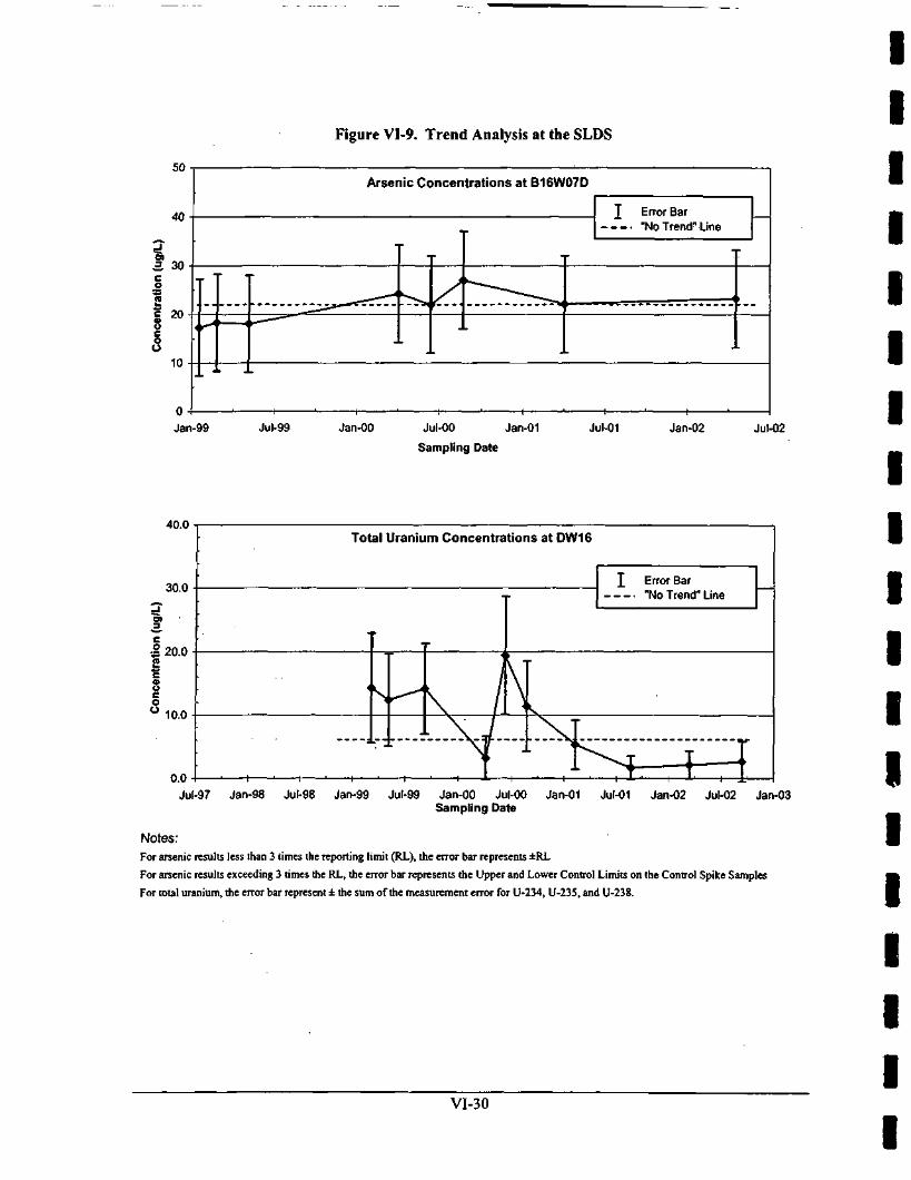
Figure VI-9. Trend Analysis at the SLDS
Arsenic Concentrations at B16W07D
I Error Bar"No Trend-Line
Jan-99 Jul-99 Jan-00 Jul-00 Jan-01
Sampling Date
Jul-01 Jan-02 Jul-02
40.0Total Uranium Concentrations at DW16
Error Bar"No Trend" Line
Jul-97 Jan-98 Jul-98 Jan-99 Jul-99 Jan-00 Jul-00 Jan-01 Jul-01 Jan-02 Jul-02 Jan-03Sampling Date
Notes:For arsenic results less than 3 times the reporting limit (RL), the error bar represents ±RL
For arsenic results exceeding 3 times the RL, the error bar represents the Upper and Lower Control Limits on the Control Spike Samples
For total uranium, the error bar represent ± the sum of the measurement error for U-234, U-235, and U-238.
VI-30

1i
Fig
• 250-
1 f.S onn
• i^^K o^^ 5 17^0 175-
• iRn .
Con
cent
ratio
n (ug
/L)
o in
-j
o r
o t_
'n
o
01
o
01
nT
c
i ,
. .
n
•
0
• Jan
ft 300-
250-
1 2 * o n n
§'•P 1CA
I Io 1no .c luu
3en .
1
ure VI-10. Trend Analysis for Wells Exceeding Investigative Limits (ILs) at the SLDS
Arsenic Concentrations at DW1<
I X^^\ 1 ^ ~<^ \ T S " ^
-99 Jul-99 Jan-00 Jul-00 Jan-01 , Jul-01Sampling Date
Arsenic Concentrations at DW15
»"No Trend" Line
T -^"
Jan-02 Jul-02 Jan-03
T Error Bar"No Trend" Line
T
^ 1\ /-99 Jul-99 Jan-00 Jul-00 Jan-01 Jul-01
Sampling Date
YJan-02 Jul-02 Jan-03
Total Uranium Concentrations at DW19
.
I ;vI Error Bar
"No Trend" Line
^ / ^NL L-T^4v _ Ty iSixii t\. i - — T^^T 1
4^^ I I1
Jan-99 Jul-99 Jan-00 Jul-00 Jan-01 Jul-01 Jan-02 Jul-02 Jan-03• Sampling Date
™ Notes:
For arsenic results less than 3 times the reporting limit (RL), the error bar represents ±RL
I F o r arsenic results exceeding 3 times the RL, the error bar represents the Upper and Lower Control Limits of the Control Spike Samples
For total uranium, the error bar represent ± the sum of the measurement error for U-234, U-235, and U-238.
1Vl-31

treated and one frill-scale batch was treated. The treated wastewater consisted of a first batch of12,000 gallons (gal) of pilot-treated wastewater and a second batch of 120,000 gal of treatedwastewater. These batches of treated wastewater were sampled and analyzed for MSD influentcriteria. The results indicated a total activity of 1.4E-06 curies (Ci) for Th, 2.9E-06 Ci foruranium (isotopic method), and O.OE+00 Ci for Ra.
Storm-Water Monitoring at the HISS
The MDNR renewed NPDES operating permit MO-0111252 for the discharge of storm waterfrom two outfalls at the HISS in 1995. These outfall locations are designated as HN01 andHN02.
Both total suspended solids and pH values were within the discharge limits at both outfalls forthe sampling events in CY1998. However, the maximum and mean gross alpha activities for bothoutfalls exceeded the ambient water quality criteria (AWQC) of 15 picocuries per liter (pCi/L).Additionally, the mean and maximum concentrations of Ra isotopes in the HN02 effluentexceeded the AWQC for combined Ra-226 and Ra-228 of 5 pCi/L. None of the AWQC for thechemical pollutants was exceeded. Furthermore, the measured concentrations of the detectedorganic pollutants were below the health advisory levels for bromacil (90 grams per liter) andAWQC for the phthalate esters of 10 CSR 20-7 for a drinking water supply.
Outfall HN03 was constructed in July 1999 to monitor storm-water run-off from the soil piles.CY1999 storm-water discharge concentrations from the HISS complied with criteria contained inthe permit and 10 CFR 20.1302. The permit expired in 2000 and negotiations between theUSAGE and MDNR as to future activity under the permit are ongoing.
In CY2000 through CY2002, storm-water discharge was monitored from three outfalls at theHISS: HN01, HN02, and HN03. No permit limits or 10 CFR 20.1302 criteria were exceeded atthe HISS in these calendar years.
Storm-Water Discharge Monitoring at the SLAPS
Site-specific permits are in place for the discharge of storm water to Coldwater Creek at theSLAPS. Historical monitoring of storm-water discharges at the SLAPS involved semiannualsampling of the effluent from two outfalls. The first of the SLAPS historical outfalls (STW-001)was located at the northwest entrance to the site, and the second historical outfall (STW-002)was located in the southwest comer of the site. As a result of insufficient flow, storm-watereffluent samples were not collected from Outfall STW-002 during CY1998.
In a NPDES-equivalent document dated October 2, 1998, MDNR established storm-waterdischarge requirements for three outfalls at the SLAPS in conjunction with the proposedconstruction of the sedimentation basin. These three storm-water discharge outfalls at the SLAPSreplaced the historical outfalls and were designated as Outfall PN01, Outfall PN02, and OutfallPN03. Outfall PN01 actually consists of two separate outfalls. Outfall PNOla is the dischargepoint for the sedimentation basin, and Outfall PNOlb is the discharge point for the emergencyspillway. Outfall PNOlb is located near historical Outfall STW-001. Th-230 concentrationsexceeded the values specified in Table 2, Appendix B of 10 CFR 20 of 15 pCi/L at each outfallin CY1998 with concentrations ranging from 1.33 to 320.3 pCi/L. (Thorium is not in the permit,and is based on annual averages per 10 CFR 20.)
VI-32

Iiiiiiiiiiiiiiiiiii
In CY1999, storm-water discharge parameters were detected below discharge requirements, withone exception. Analytical results for the July 1, 1999, sample for Outfall PN03 indicated totalcopper at 101 ug/L, which is above the discharge limit of 84 ug/L. The CY1999 storm-waterdischarges from the SLAPS also complied with criteria contained in 10 CFR 20.1302. Theaverage annual concentration of radioactive material released in CY1999 storm-water dischargesdid not exceed the values specified in Table 2, Appendix B of 10 CFR 20 (i.e., for a mixture ofradionuclides, the SOR is less than unity).
For CY2000, storm-water discharge results indicated an exceedence of the discharge limit of84 ug/L for total recoverable copper at Outfall PN03 in February 2000. The result reported was88.6 ug/L. The CY2000 storm-water discharges from the SLAPS complied with the criteriacontained in 10 CFR 20.1302.
Chemical sample data results for CY2001 storm-water discharges indicated there were twoexceedences at Outfall PN03 of the discharge limit of 1.0 microliters per liter per hour (uL/L/hr)for sertleable solids. These exceedences occurred in September and October 2001. The respectiveresults were 1.56 uL/L/hr and 4.0 uL/L/hr. Both exceedences were the result of an intenserainfall event. The October 2001 result for Outfall PN03 revealed that the sample also exceededthe total recoverable copper limit of 84 ug/L with a result of 160 ug/L. The average annualconcentration of radioactive material released in CY2001 storm-water discharges did not exceedthe values specified in Table 2 of Appendix B of 10 CFR 20.
Discharge limits were exceeded for copper at Outfall PNOla during the second quarter ofCY2002. The concentration of total recoverable copper (100 ug/L) exceeded the daily maximumlimit of 84 ng/L. Otherwise, discharge limits were not exceeded at the SLAPS for CY2002.
Exceedances at the outfalls were detected after rainfall events that corresponded with backfillingoperations. In addition, the exceedances that occurred in 2001 occurred when PN03 was pluggedand water was being diverted to PNOla.
In accordance with a letter dated February 19, 2002, from MDNR, sampling at Outfall PN02 wasreduced to once a year, until the drainage area is affected by a soil disturbance. Outfall PN03 hasbeen discontinued as a sampling location in accordance with a letter by MDNR dated February19,2002.
Site Radiological Monitoring
Program Overview (SLDS)
Site radiological monitoring consisted of collecting gamma radiation, airborne particulateradionuclide, and radon data. The data were used to assess the magnitude of radiologicalexposures to the general public. Radon flux monitoring was not required at the SLDS.
Applicable Standards
10 CFR 20
The regulatory dose limit for members of the public is 100 millirem per year (mrem/yr) from allpathways, as stated in 10 CFR 20.1301. Compliance with the dose limit in 10 CFR 20.1301 canbe demonstrated in one of the two following ways [§20.1302(b)(l) and (2)].
Vl-33

1. Demonstrating by measurement or calculation that the total effective dose equivalent (TEDE)to the individual likely to receive the highest dose from the SLDS operations does not exceedthe annual dose limit (100 mrem/yr).
2. Demonstrating that (/) the annual average concentration of radioactive material released ingaseous and liquid effluents at the boundary of the unrestricted area does not exceed thevalues specified in Table 2 of Appendix B to Part 20 and (») if an individual werecontinuously present in an unrestricted area, the dose from external sources would not exceed2 millirem per hour (mrem/hr).
Gamma radiation, airborne particulate radionuclide, and radon data from the site were used toevaluate the cumulative dose to a hypothetically impacted individual (member of the public)from exposure to radiological contaminants at the SLDS in order to demonstrate compliancewith 10CFR 20.1301.
Radon was also compared to the regulatory criterion listed in 10 CFR 20, Table 2 ofAppendix B, of 0.3 picocuries per liter (pCi/L) (at 30% equilibrium) average annualconcentration above background.
40 CFR 61
Airborne particulate radionuclide data from the site were used to calculate the effective doseequivalent (EDE) to a critical receptor. The National Emission Standards for Hazardous AirPollutant (NESHAP) standard of EDE to a critical receptor from radionuclide emissions is10 mrem/yr as stated in 40 CFR 61, Subpart I (National Emission Standards for Emissions ofRadiomtclides Other Than Radon From Federal Facilities Other Than Nuclear RegulatoryCommission Licensees and Not Covered By Subpart H).
Gamma Radiation Monitoring
Monitoring Overview
Gamma radiation was measured using thermoluminescent dosimeters (TLDs). TLDs at the SLDSwere located at areas assumed to be representative of areas accessible to the public. At eachmonitoring station, the TLDs were placed approximately 3 feet above the ground surface inside ahousing shelter. The TLDs were collected quarterly and sent to an off-site vendor for analysis.Gamma radiation monitoring was performed at the SLDS at five locations during CY1999through CY2001 and at four locations in CY2002. Gamma radiation was not monitored at theSLDS during CY1998. Station DA-5 was eliminated in October 2001 after it was determined tobe a redundant location due to its proximity to DA-3.
Monitoring Program Results
The gamma radiation data collected from each location during CY1999 to CY2002 werecorrected for background, shelter absorption, and fade and were normalized to exactly one yearto calculate an annual dose. The corrected annual gamma radiation monitoring results arepresented in Table VI-6.
VI-34

IIIIIIIIIIIIIIIIIII
Table VI-6. External Gamma Radiation Monitoring Results at the SLDS
MonitoringLocation
SLDS
MonitoringStation
DA-1DA-2DA-3DA-4DA-5
CY1998TLD Data
CY1999"TLD Data
CY2000TLD Data
CY2001TLD Data
CY2002TLD Data
(mrem/yr)NANANANANA
00900
1821560
15930184
13134518
NA8 Station names and locations may have varied slightly from year to year. The exact location of each station can be
found in the Annual Environmental Monitoring Data and Analysis Report for the respective year.NA Not monitored or station eliminated
Data Analysis
Gamma radiation data from the SLDS were used to calculate an average dose rate, and an annualdeep dose equivalent (DDE) to a hypothetically maximally exposed individual. The average doserate was compared to the 10 CFR 20.1302(b)(2)(ii) limit of 2 mrem/hr. A summary of calculatedgamma radiation dose rates is presented in Table VI-7. The average dose rate during CY1999 toCY2002 was less than the 10 CFR 20.1302(b)(2)(ii) limit of 2 mrem/hr.
Table VI-7. External Gamma Dose Rate at the SLDS
19981999200020012002
Maximum AverageDose Rate above
Background9
10 CFR 20 Limit(2 mrem/yr)
(mrem/hr)NA0.1<0.1<0.1<0.1
22222
Annual CalendarYear Dose
10 CFR 20 Limit(100 mrem/yr)
(mrem/yr)NA0.00.00.10.1
100100100100100
" Calculated by dividing the annual gamma radiation result by 8760 hours, the number of hours in a year, for eachlocation.
NA Not available
The annual dose to a member of the public from gamma radiation was added to dose rates fromother pathways to demonstrate compliance with the 10 CFR 20.1302(b)(l) limit of 100 mrem/yrduring CY1999 to CY2002. The annual calendar year doses for CY1999 to CY2002 were lessthan the 100 mrem/year for all pathways.
Five-year Trend Analysis
The annual dose to a member of the public from gamma radiation at the SLDS was far below the10 CFR 20.1302(b)(2)(ii) limit for all years with negligible variance from year to year. Therewas a minute upward trend over the time period; however, when compared to the regulatorylimit, the trend was insignificant.
VI-35

Airborne Paniculate Monitoring
Monitoring Overview
Airborne radioactive participates result from radioactive material in soil (or other sources) thatbecomes suspended in the air. Airborne radioactive particulates were measured by drawing airthrough a filter membrane with an air sampling pump placed approximately 3 feet above theground and then analyzing the material contained on the filter. The results of the analysis, whencompared to the amount of air drawn through the filter, were reported as radioactive contaminantconcentrations in microcuries per milliliter (uCi/mL).
Perimeter air sampling for radiological particulates was not conducted at the SLDS during CY1998to CY2002 due to the insignificant potential for material to become airborne at the site. Particulateair monitors were located at excavation perimeter locations on the SLDS. Air particulate samplesare collected during active excavation at the SLDS and analyzed at the SLS radioanalyticallaboratory. Airborne particulate data were not available for CY1998 and CY1999.
Monitoring Program Results
The annual dose was calculated for a hypothetically maximally exposed individual. For CY 1998and CY1999, the annual dose was calculated by applying relevant modeling parameters given thesize of known work areas, meteorological conditions, and potential exposure durations in lieu ofavailable monitoring data. The average annual gross alpha and gross beta concentrations and theannual dose rate to a hypothetically maximally exposed individual are presented in Table VI-8.
Table VI-8. Air Particulate Monitoring at the SLDS
CalendarYear19981999200020012002
Average Annual Gross AlphaConcentration (uCi/mL)
NANA
1.2E-145.2E-151.3E-15
Average Annual Gross BetaConcentration (jiCi/mL)
NANA
1.3E-136.0E-142.3E-14
Annual DoseRate
(mrem/yr)0.30.8
<0.1<0.70.2
NA Not available
Data Analysis
Airborne particulate data were used to calculate radionuclide emission rates to determine if theEDE to a member of the public exceeded the 40 CFR 61 standard of 10 mrem/yr. The estimatedEDE was added to the radiological doses from other pathways to determine if the TEDE to amember of the public exceeded the 10 CFR 20 limit of 100 mrem/yr. A comparison of the EDEdue to airborne particulate radionuclides at the SLDS and the regulatory limits is presented inTable VI-9.
VI-36

IIIIIIIIIIIIIIIIIII
Table VI-9. Airborne Particulate Dose Rate at the SLDS
Calendar Year
19981999200020012002
Annual Dose Rate40 CFR 61Standard
(10 mrem/yr)
10 CFR 20 Limit(100 mrem/yr)
(mrem/yr)*
0.8<0.1<0.70.2
1010101010
100100100100100
* Value is less than 10 percent of the dose standard in 40 CFR 61.102.
As shown in Table VI-9, the annual dose to a member of the public from air particulateradionuclides did not exceed the 40 CFR 61 standard of 10 mrem/yr during CY1998 to CY2002.
Five-year Trend Analysis
The annual dose to a member of the public from airborne particulate radionuclides at the SLDSwas far below the 40 CFR 61 standard and did not really vary from year to year. There is a smalldownward trend over the time period; however, when compared to the regulatory standard, thetrend is insignificant. The average annual gross alpha and gross beta results demonstrate a slightdownward trend over the period as well.
Radon Monitoring
Monitoring Overview
Airborne radon monitoring was performed at the SLDS using alpha track decectors (ATDs) tomeasure radon emissions. The detectors were collocated with the TLDs at the site. The ATDswere collected semi-annually. Radon concentrations were used to calculate an EDE to ahypothetically maximally exposed individual and added to dose rates from other pathways todemonstrate compliance with the 10 CFR 20 dose limit of 100 mrem/yr. Recorded radonconcentrations were also evaluated based on the regulatory criterion listed in 10 CFR 20,Appendix B of 0.3 pCi/L (at 30% equilibrium) average annual concentration above background.Radon monitoring was performed at the SLDS at five locations during CY1999 through CY2001and at four locations in CY2002. Radon was not monitored at the SLDS during CY1998. StationDA-5 was eliminated in October 2001 after it was determined to be a redundant location due toits proximity to DA-3.
Monitoring Program Results
The radon data collected from each location during CY1999 to CY2002 were corrected forbackground and was normalized to exactly one year to calculate an annual dose rate. Thecalculated annual radon monitoring results are presented in Table VI-10.
VI-37

Table VI-10. Radon Monitoring at the SLDS
MonitoringLocation
SLDS
MonitoringStation
DA-1DA-2DA-3DA-4DA-5
CY1998Radon Data
CY1999"Radon Data
CY2000Radon Data
CY2001Radon Data
CY2002Radon Data
(pCi/L)NANANANANA
0.00.00.00.00.2
0.0. 0.0
0.00.00.0
0.10.10.00.00.0
0.00.00.10.0NA
3 Station names and locations may have varied slightly from year to year. The exact location of each station can befound in the Annual Environmental Monitoring Data and Analysis Report for the respective year.
NA Not monitored or station eliminated
Data Analysis
Radon data from the SLDS were used to calculate an average annual concentration and an annualEDE to a hypothetically maximally exposed individual. The average concentration wascompared to the 10 CFR 20, Appendix B value of 0.3 pCi/L (at 30% equilibrium) average annualconcentration above background. The annual dose was added to dose rates from other pathwaysto demonstrate compliance with the 10 CFR 20 limit. A summary of the radon concentrationsabove background and calculated dose rates is presented in Table VI-11.
Table VI-11. Radon Concentration and Dose Rate at the SLDS
CalendarYear
19981999200020012002
Average AnnualConcentration
Above Background
10CFR20App. B(03 pCi/L)
(pCi/L)NA<0.10.0
<0.1<0.1
0.30.30.30.30.3
Annual Dose Rate 10 CFR 20 Limit(100 mrem/yr)
(mrem/yr)NA0.00.00.20.0
100100100100100
NA Not available
As shown in Table VI-11, the average annual concentrations above background during CY1999to CY2002 were less than the 10 CFR 20 Appendix B value of 0.3 pCi/L.
Five-year Trend Analysis
The annual radon concentrations at the SLDS were far below the 10 CFR 20 limit with negligiblevariance from year to year. There was a minute upward trend for dose rates over the time period;however, when compared to the regulatory limit, the trend was insignificant. The average annualconcentration of radon remained approximately the same for the period.
VI-38

IIIIIIIIIIIIIIIIIII
Site Radiological Monitoring
Program Overview (SLAPS)
Site radiological monitoring consisted of collecting gamma radiation, airborne particulateradionuclide, and radon data. The data were used to assess the magnitude of radiologicalexposures to the general public. Radon flux monitoring was not required at the SLAPS.
Applicable Standards
10 CFR 20
The regulatory dose limit for members of the public is 100 mrem/yr from all pathways as statedin 10 CFR 20.1301. Compliance with the dose limit in 10 CFR 20.1301 can be demonstrated inone of the two following ways [§20.1302(b)(l) and (2)].
1. Demonstrating by measurement or calculation that the TEDE to the individual likely toreceive the highest dose from the SLAPS operations does not exceed the annual dose limit(100 mrem/yr).
2. Demonstrating that (/) the annual average concentration of radioactive material released ingaseous and liquid effluents at the boundary of the unrestricted area does not exceed thevalues specified in Table 2 of Appendix B to Part 20 and (if) if an individual werecontinuously present in an unrestricted area, the dose from external sources would not exceed2 mrem/hr.
Gamma radiation, airborne particulate radionuclide, and radon data from the site were used toevaluate the cumulative dose to a hypothetically impacted individual (member of the public)from exposure to radiological contaminants at the SLAPS in order to demonstrate compliancewith 10 CFR 20.1301.
Radon was also compared to the regulatory criterion listed in 10 CFR 20, Appendix B, of0.3 pCi/L (at 30% equilibrium) average annual concentration above background.
40 CFR 61
Airborne particulate radionuclide data from the site were used to calculate the EDE to a criticalreceptor. The NESHAP standard of EDE to a critical receptor from radionuclide emissions is10 mrem/yr as stated in 40 CFR 61, Subpart I (National Emission Standards for Emissions ofRadionuclides Other Than Radon From Federal Facilities Other Than Nuclear RegulatoryCommission Licensees and Not Covered By Subpart H).
Gamma Radiation Monitoring
Monitoring Overview
Gamma radiation was measured using TLDs. TLDs at the SLAPS were located at the siteperimeter. At each monitoring station, the TLDs were placed approximately 3 feet above theground surface inside a housing shelter. The TLDs were collected quarterly and sent to an off-
Vl-39

site vendor for analysis. Gamma radiation monitoring was performed at the SLAPS at fourlocations during CY1998 and at six locations during CY1999 through CY2002.
Monitoring Program Results
The gamma radiation data collected from each location during CY1998 to CY2002 werecorrected for background, shelter absorption, and fade, and was normalized to exactly one yearfor the purpose of comparison to an annual dose. The calculated annual gamma radiation resultsare presented in Table VI-12.
Table VI-12. External Gamma Radiation Monitoring at the SLAPS
MonitoringLocation
SLAPS
MonitoringStation
PA-1PA-2PA-3PA-4PA-5PA-6
CY1998*TLD Data
CY1999"TLD Data
CY2000TLD Data
CY2001TLD Data
CY2002TLD Data
(mrem/yr)NA3274
245047
NA
4778
3303089
1126
3114227106
16214605813
105
1571458457
108
" Station names and locations may have varied slightly from year to year. The exact location of each station can befound in the Annual Environmental Monitoring Data and Analysis Report for the respective year.
NA Not monitored or station eliminated
Data Analysis
Gamma radiation data from the SLAPS was used to calculate an average dose rate and an annualDDE to a hypothetically maximally exposed individual. The average dose rate was compared tothe 10 CFR 20.1302(b)(2)(ii) limit of 2 mrem/hr. A summary of the calculated gamrna radiationdose rates are presented in Table VI-13.
Table VI-13. External Gamma Dose Rate at the SLAPS
CalendarYear
19981999200020012002
Maximum AverageDose Rate above
Background"
10 CFR 20 Limit(2 mrem/yr)
(mrem/hr)0.3
<0.1<0.1<0.1<0.1
22222
Annual Dose Rate 10 CFR 20 Limit(100 mrem/yr)
(mrem/yr)0.10.0
L_ 0.1
0.10.1
100100100100100
* Calculated by dividing the annual gamma radiation result by 8760 hours, the number of hours in a year, for eachlocation.
The annual dose to a member of the public from gamma radiation was added to dose rates fromother pathways to demonstrate compliance with the 10 CFR 20 limit of 100 mrem/yr duringCY1998 to CY2002. The average dose rate during CY1999 to CY2002 was less than the 10 CFR20.1302(b)(2)(ii) limit of 2 mrem/hr.
VI-40

IIIIIIIIIIIIIIIIIII
Five-year Trend Analysis
The annual dose to a member of the public from gamma radiation at the SLAPS was far belowthe 10 CFR 20 limit for all years with negligible variance from year to year.
Airborne Particulate Monitoring
Monitoring Overview
Airborne radioactive particulates result from radioactive material in soil (or other sources) thatbecome suspended in the air. Airborne radioactive particulates were measured by drawing airthrough a filter membrane with an air sampling pump placed approximately 3 feet above theground and then analyzing the material contained on the filter. The results of the analysis, whencompared to the amount of air drawn through the filter, were reported as radioactive contaminantconcentrations in uCi/mL.
Site perimeter air sampling for radiological particulates was conducted at the SLAPS duringCY1999 to CY2002. Air paniculate samples were collected weekly at the SLAPS and analyzedat the SLS radioanalytical laboratory. Airborne particulate data were not available for CY1998.
Monitoring Program Results
The annual dose was calculated for a hypothetically maximally exposed individual. For CY1998,the annual dose was calculated by applying relevant modeling parameters given the size ofknown work areas, meteorological conditions, and potential exposure durations in lieu ofavailable monitoring data. The average annual gross alpha and gross beta concentrations and theannual dose rate to a hypothetically maximally exposed individual are presented in Table VI-14.
Table VI-14. Air Particulate Monitoring at the SLAPS
CalendarYear19981999200020012002
Average Annual Gross AlphaConcentration (uCi/mL)
NA2.3E-153.5E-155.6E-153.1E-15
Average Annual Gross BetaConcentration (uCi/mL)
NA3.5E-144.1E-146.3E-144.2E-14
Annual Dose(mrem/yr)
7.66.46.49.44.8
NA Not available
Data Analysis
Airborne particulate data were used to calculate radionuclide emission rates to determine if theEDE to a member of the public exceeded the 40 CFR 61 standard of 10 mrem/yr. The estimatedEDE was added to the radiological doses from other pathways to determine if the TEDE to amember of the public exceeded the 10 CFR 20 limit of 100 mrem/yr. A comparison of the EDEdue to airborne particulate radionuclides at the SLAPS to the regulatory standards is presented inTableVI-15.
VI-41

Table VI-15. Airborne Particulate Dose Rate at the SLAPS
Calendar Year
19981999200020012002
Annual Dose Rate40 CFR 61Standard
(10 mrem/yr)
10 CFR 20 Limit(100 mrem/yr)
(mrem/yr)7.66.46.49.44.8
1010101010
100100100100100
As shown in Table VI-15, the annual dose to a member of the public from air particulateradionuclides did not exceed the 40 CFR 61 standard of 10 mrem/yr CYI998 to CY2002.
Five-year Trend Analysis
The annual dose to a member of the public from airborne particulate radionuclides at the SLAPSwas below the 40 CFR 61 standard for all years. There is an overall slight downward trendduring the time period. The average annual gross alpha and gross beta results have remainedapproximately the same over the period. This may be due to ongoing remediation at the SLAPS.
Radon Monitoring
Monitoring Overview
Airborne radon monitoring was performed at the SLAPS using ATDs to measure radonemissions. The detectors were collocated with the TLDs at the site. The ATDs were collectedsemi-annually. Radon concentrations were used to calculate an EDE to a hypotheticallymaximally exposed individual and added to dose rates from other pathways to demonstratecompliance with the 10 CFR 20 dose limit of 100 mrem/yr. Recorded radon concentrations werealso evaluated based on the regulatory criterion listed in 10 CFR 20, Appendix B of 0.3 pCi/L (at30% equilibrium) average annual concentration above background. Radon monitoring wasperformed at the SLAPS at four locations during CY1998 and at six locations during CY1999through CY2002.
Monitoring Program Results
The radon data collected from each location during CY1998 to CY2002 were corrected forbackground and was normalized to exactly one year to calculate an annual dose. The calculatedannual radon monitoring results are presented in Table VI-16.
Table VI-16. Radon Monitoring at the SLAPS
MonitoringLocation
SLAPS
MonitoringStation
PA-1PA-2PA-3PA-4PA-5PA-6
CY1998"Radon Data
CY1999"Radon Data
CY2000Radon Data
CY2001Radon Data
CY2002Radon Data
(pCi/L)NA0.20.20.40.2NA
0.60.00.11.50.00.0
0.10.00.00.30.20.0
0.20.10.00.10.00.2
0.10.10.00.10.00.0
" Station names and locations may have varied slightly from year to year. The exact location of each station can befound in the Annual Environmental Monitoring Data and Analysis Report for the respective year.
NA Not monitored
VI-42

IIIIIIIIIIIIIIIIIII
Data Analysis
Radon data from the SLAPS were used to calculate an average annual concentration and anannual EDE to a hypothetically maximally exposed individual. The average concentration wascompared to the 10 CFR 20, Appendix B value of 0.3 pCi/L (at 30% equilibrium) average annualconcentration above background. The annual dose was added to dose rates from other pathwaysto demonstrate compliance with the 10 CFR 20.1301 limit. A summary of the radonconcentrations above background and calculated dose rates is presented in Table VI-17.
Table VI-17. Radon Concentration and Dose Rates at the SLAPS
CalendarYear
19981999200020012002
Average AnnualConcentration
Above Background
10CFR20App. B(0.3 pCi/L)
(pCi/L)<0.20.370.10.1
<0.1
0.30.30.30.30.3
Annual Dose Rate 10 CFR 20 Limit(100 mrem/yr)
(mrem/yr)NA0.00.00.20.0
100100100100100
NA Not available
As shown in Table VI-17, the average annual concentrations above background during CY1999and CY2002 were less than the 10 CFR 20 Appendix B value of 0.3 pCi/L with the exception of1999. Although the average annual radon concentration exceeded the Appendix B value in 1999,compliance with the 10 CFR 20 limit of 100 mrem/yr was demonstrated through calculation ofthe TEDE to the individual likely to receive the highest dose.
Five-year Trend Analysis
The annual radon concentrations at the SLAPS were below the 10 CFR 20 limit with negligiblevariance from year to year (with the exception of 1999). There was no apparent trend for annualdose over the time period. The average annual concentrations of radon had a slight downwardtrend for the period.
Site Radiological Monitoring
Program Overview (HISS)
Site radiological monitoring consisted of collecting gamma radiation, airborne particulateradionuclide, radon, and radon flux data. The data were used to assess the magnitude ofradiological exposures to the general public.
Applicable Standards
10 CFR 20
The regulatory dose limit for members of the public is 100 mrem/yr from all pathways as statedin 10 CFR 20.1301. Compliance with the dose limit in 10 CFR 20.1301 can be demonstrated inone of the two following ways [§20.1302(b)(l) and (2)].
VI-43

1. Demonstrating by measurement or calculation that the TEDE to the individual likely toreceive the highest dose from the HISS operations does not exceed the annual dose limit(lOOmrem/yr).
2. Demonstrating that (/) the annual average concentration of radioactive material released ingaseous and liquid effluents at the boundary of the unrestricted area does not exceed thevalues specified in Table 2 of Appendix B to Part 20 and (/;') if an individual werecontinuously present in an unrestricted area, the dose from external sources would not exceed2 mrem/hr.
Gamma radiation, airborne particulate radionuclide, and radon data from the site were used toevaluate the cumulative dose to a hypothetically impacted individual (member of the public)from exposure to radiological contaminants at the HISS in order to demonstrate compliance with10 CFR 20.1301.
Radon was also compared to the regulatory criterion listed in 10 CFR 20, Appendix B, of0.3 pCi/L (at 30% equilibrium) average annual concentration above background.
40 CFR 61
Airborne particulate radionuclide data from the site were used to calculate the EDE to a criticalreceptor. The NESHAP standard of EDE to a critical receptor from radionuclide emissions is10 mrem/yr, as stated in 40 CFR 61, Subpart I (National Emission Standards for Emissions ofRadionuclides Other Than Radon From Federal Facilities Other Than Nuclear RegulatoryCommission Licensees and Not Covered By Subpart H).
40 CFR 192
40 CFR 192 requires control of residual radioactive materials to provide reasonable assurancethat releases of radon-222 (Rn-222) will not exceed an average release rate of 20 picocuries persquare meter per second (pCi/m2/s). Radon flux data from the piles on the HISS were used tocalculate an average radon release rate to compare to the 40 CFR 192 limit and to verify the linerover the piles .was effectively intact.
Gamma Radiation Monitoring
Monitoring Overview
Gamma radiation was measured using TLDs. TLDs at the HISS were located at the siteperimeter. At each monitoring station, the TLDs were placed approximately 3 feet above theground surface inside a housing shelter. The TLDs were collected quarterly and sent to an off-site vendor for analysis. Gamma radiation monitoring was performed at the HISS at eightlocations during CY1998, at six locations during CY1999 through CY2001, and at five locationsduring CY2002.
Monitoring Program Results
The gamma radiation data collected from each location during CY1998 to CY2002 werecorrected for background, shelter absorption, and fade and was normalized to exactly one year tocalculate an annual dose. The corrected annual gamma radiation results are presented inTable VI-18.
Vi-44

IIIIIIIIIIIIIIIIIII
Table VMS. External Gamma Radiation Monitoring at the HISS
MonitoringLocation
HISS
MonitoringStation
HA-1HA-2HA-3HA-4HA-5HA-6
158
CY1998"TLD Data
CY1999"TLD Data
CY2000TLD Data
CY2001TLD Data
CY2002TLD Data
(mrem/yr)0
5910143NA0
27240
0523747
NA0
NA35NA
1 1514259320
NANANA
11066769492
NANANA
904920
NA41
NANANA
" Station names and locations may have varied slightly from year to year. The exact location of each station can befound in the Annual Environmental Monitoring Data and Analysis Report for the respective year.
NA Not monitored or station eliminated
Data Analysis
Gamma radiation data from the HISS were used to calculate an average dose rate and an annualEDE to a hypothetically maximally exposed individual. The average dose rate was compared tothe 10 CFR 20.1302(b)(2)(ii) limit of 2 mrem/hr. A summary of the calculated gamma radiationdose rates is presented in Table VI-19.
Table VI-19. External Gamma Dose Rate at the HISS
CalendarYear
19981999200020012002
Maximum AverageDose Rate above
Background'
10 CFR 20 Limit(2 mrem/yr)
(mrem/hr)0.1<0.10.1O.I0.1
22222
Annual Dose Rate 10 CFR 20 Limit(100 mrem/yr)
(mrem/yr)0.30.20.20.20.1
100100100100100
* Calculated by dividing the annual gamma radiation result by 8760 hours for each location.
The annual dose to a member of the public from gamma radiation was added to dose rates fromother pathways to demonstrate compliance with the 10 CFR 20 limit of 100 mrem/yr duringCY1998 to CY2002. The average dose rate during CY1999 to CY2002 was less than the 10 CFR20.1302(b)(2)(ii) limit of 2 mrem/hr.
Five-year Trend Analysis
The annual dose to a member of the public from gamma radiation at the HISS was far below the10 CFR 20 limit for all years with negligible variance from year to year. The annual dose had aslight downward trend over the period.
VI-45

Airborne Particulate Monitoring
Monitoring Overview
Airborne radioactive participates result from radioactive material in soil (or other sources) thatbecome suspended in the air. Airborne radioactive particulates were measured by drawing airthrough a filter membrane with an air sampling pump placed approximately 3 feet above theground and then analyzing the material contained on the filter. The results of the analysis, whencompared to the amount of air drawn through the filter, were reported as radioactive contaminantconcentrations in uCi/mL.
Site perimeter air sampling for radiological particulates was conducted at the HISS during CY1999to CY2002. Air particulate samples were collected weekly at the HISS and analyzed at the SLSradioanalytical laboratory. Airborne particulate data were not available for CY1998.
Monitoring Program Results
The annual dose was calculated for a hypothetically maximally exposed individual. For CY1998,the annual dose was calculated by applying relevant modeling parameters given the size ofknown work areas, meteorological conditions, and potential exposure durations in lieu ofavailable monitoring data. The average annual gross alpha and gross beta concentrations and theannual dose rate to a hypothetically maximally exposed individual are presented in Table VI-20.
Table VI-20. Air Particulate Monitoring at the HISS
CalendarYear19981999
^•,-i2Qm*m20012002
Average Annual Gross AlphaConcentration (uCi/mL)
NA2.1E-152.0&1.5vis aisai&riir2.0E-151.7E-15
Average Annual Gross BetaConcentration (jiCi/mL)
NA3.5E-14S.lSflAvuft2.9E-142.5E-14
Annual Dose(mrem/yr)
0.10.82.17.87.8
NA Not available . . .
Data Analysis
Airborne particulate data were used to calculate radionuclide emission rates to determine if theEDE to a member of the public exceeded the 40 CFR 61 standard of 10 mrem/yr. The estimatedEDE was added to the radiological doses from other pathways to determine if the TEDE to amember of the public exceeded the 10 CFR 20 limit of 100 nirerri/yf. A comparison of the EDEdue to airborne particulate radionuclides at the HISS and the regulatory limits is presented inTable VI-21.
VI-46

Table VI-21. Airborne Participate Dose Rate at the HISS
Calendar Year
19981999200020012002
Annual Dose Rate40 CFR 61Standard
(10 mrem/yr)
10 CFR 20 Limit(100 mrem/yr)
(mrem/yr)0.10.82.17.87.8
1010101010
100100100100100
As shown in Table VI-21, the annual dose to a member of the public from air particulateradionuclides did not exceed the 40 CFR 61 standard of 10 mrem/yr during CY1998 to CY2002.
Five-year Trend Analysis
The annual dose to a member of the public from airborne particulate radionuclides at the HISSwas below both the 40 CFR 61 standard for all years. There is an overall upward trend during thetime period. This may be due to active remediation in CY2000 and CY2001. The average annualgross alpha and gross beta results had a slight downward trend over the period. CY2002 grossalpha and gross beta results were less than the respective CY2001 results indicating that theremay be lower airborne particulate emissions after the HISS piles had been removed in CY2000andCY2001.
Radon Monitoring
Monitoring Overview
Airborne radon monitoring was performed at the HISS using ATDs to measure radon emissions.The detectors were collocated with the TLDs at the site. The ATDs were collected semi-annually. Radon concentrations were used to calculate an EDE to a hypothetically maximallyexposed individual and added to dose rates from other pathways to demonstrate compliance withthe 10 CFR 20 dose limit of 100 mrem/yr. Recorded radon concentrations were also evaluatedbased on the regulatory criterion listed in 10 CFR 20, Appendix B of 0.3 pCi/L (at 30%equilibrium) average annual concentration above background. Radon monitoring was performedat the HISS at eight locations during CY1998, at six locations during CY1999 through CY2001,and at five locations during CY2002.
Radon flux sampling was used to measure emission rates of radon from the surface of thecontaminated soil piles. Radon flux monitoring was performed using 10-inch diameter activatedcharcoal canisters placed on a pre-determined grid. The canisters were attached to the storagepile's cover surface for 24 hours, and then the canisters were retrieved and sent to an off-sitelaboratory for analysis in accordance with Appendix B of 40 CFR 61. Radon flux monitoringwas performed at the HISS piles during CY1998 through CY2000. The piles were remediatedduring CY2000 and CY2001 and radon flux monitoring was no longer required.
VI-47

Perimeter Radon A IDs
Monitoring Program Results
The radon data collected from each location during CY1998 to CY2002 were corrected forbackground and were normalized to exactly one year to calculate an annual dose. The calculatedannual radon monitoring results are presented in Table VI-22.
Table VI-22. Radon Monitoring at the HISS
MonitoringLocation
HISS
Monitoring'Station
HA-1HA-2HA-3HA-4HA-5HA-6
158
CY1998ATD Data
CY1999ATD Data
CY2000ATD Data
CY2001ATD Data
CY2002ATD Data
(mrem/yr)0.20.20.20.2NA0.20.20.20.2
0.00.00.10.0NA0.0NA0.0NA
0.20.00.00.10.00.0NANANA
0.20.10.00.10.10.0NANANA
0.00.00.1NA0.00.0NANANA
" Station names and locations may have varied slightly from year to year. The exact location of each station can befound in the Annual Environmental Monitoring Data and Analysis Report for the respective year.
NA Not monitored
Data Analysis
[on data from the HISS, .were used to calculate an ayerageannual concentration and an annuali'"'to a hypothetically'"m'aximally exposed individual/ 'The' average concentration was
compared to the 10 CFR 20, Appendix B value of 0.3 pCi/L (at 30% equilibrium) average annualconcentration above background. The annual dose was added to dose rates from other pathwaysto demonstrate compliance with the 10 CFR 20.1301 limit. A summary of the radonconcentrations above background and calculated dose rates are presented in Table VI-23.
Table VI-23. Radon Concentration and Dose Rate at the HISS
CalendarYear
19981999200020012002
Average AnnualConcentration
Above Background
10 CFR 20 App. B(0.3 pCi/L)
(pCi/L)0.2
<0.1<0.10.1
O.I
0.30.30.30.30.3
Annual Dose Rate 10 CFR 20 Limit(100 mrem/yr)
(mrem/yr)NA0.20.40.20.1
100100100100100
NA Not available
As shown in Table VI-23, the average annual concentrations above background during CY1999to CY2002 were less than the 10 CFR 20 Appendix B value of 0.3 pCi/L.
VI-48

IIIIIIIIIIIIIIIIIII
Five-year Trend Analysis
The annual radon concentration at the HISS was below the 10CFR 20 limit with negligiblevariance from year to year. There was a slight downward trend for annual dose over the timeperiod. The average annual concentration of radon also had a slight downward trend for theperiod.
Radon Flux
Monitoring Program Results
The radon flux data collected from each location on the HISS piles during CY1998 to CY2000were used to calculate an average radon release rate for the site. The calculated average radonrelease rates are presented in Table VI-24. Removal of the HISS stockpiles was conductedduring 2001.
Data Analysis
Radon release rate data from the HISS were compared to the 40 CFR 192 limit of 20 pCi/m2/s. Asummary of the radon flux monitoring is presented in Table VI-24.
Table VI-24. Radon Release Rate at the HISS
CalendarYear
199819992000
Average RadonRelease Rate
10 CFR 20 App. B(20 pCi/m2/s)
(pCi/m2/s)0.41.30.9
202020
As shown in Table VI-24, the average radon release rate from the site did not exceed the 40 CFR192 limit of 20 PCi/m2/s during CY1998 to CY2000.
Five-year Trend Analysis
The average radon release rate at the HISS was far below the 40 CFR 192 limit with negligiblevariance from year to year. There was no apparent trend for the average radon release rate overthe time period. These data indicate that the liner was effective at controlling the potentialrelease of radon.
Confirmatory Soil Sampling Program
Final status survey confirmatory sampling has been conducted at properties where removal orremedial actions have taken place. The purpose of this confirmatory sampling is to demonstratethat the removal or remedial action has been completed and the residual contamination is belowthe removal or remedial goal. The USAGE evaluates the results to ensure the residualconcentrations in the excavation meet the SLDS ROD remediation criteria for the SLDSproperties, and the removal action criteria in the applicable EE/CA for the North St. LouisCounty sites properties. The following table summarizes SLS completed actions:
VI-49

Table VI-25. SLS Confirmatory Soil Sampling Program Completed Actions
Site Location Document Completed ActionNorth St.LouisCounty
SLAPS-VPSt. Bridge
St. Denis Post-Remedial Action Report forthe St. Denis Bridge Area, July1999 (USAGE 1999c).
The USAGE informed the City ofFlorissant that the soil with residualradioactive contamination abovecriteria in the areas impacted by thenew bridge installation had beenremoved.
SLDS DT-1Archer Daniels Midland(ADM) VP
Final Status Survey EvaluationReport for the St. Louis DowntownSite Archer Daniels MidlandVicinity Property (DT-1)(USACE2002b)
No removal action required; theproperty was released withoutradiological restrictions.
SLDS DT-15City OwnedMetropolitan SewerDistrict (MSD)Salisbury Lift StationVP
Final Status Survey EvaluationReport for the St. Louis DowntownSite City- Owned Property North(MSD) Salisbury Lift StationVicinity Property (USAGE 2001 f)-
No removal action required; theproperty was released withoutradiological restrictions.
SLDS Mallinckrodt Plant 2 Post-Remedial Action Report forthe Accessible Soils Within the St.Louis Downtown Site Plant 2Property (USACE 2002a).
Residual radioactivity in theaccessible areas in Plant 2 met therequirements of the remedial designand was below the 15/15/50 SLDSROD remediation criteria. Inaddition, analytical results for arsenicand cadmium were below the SLDSremediation criteria.
North St.LouisCounty
SLAPS-VP IA-9 St. Louis Airport Site InvestigationArea 9 Final Status SurveyEvaluation, Berkeley Salt StorageArea (IA-9sr-S.urve}>^^it 1),(USACE 200QC). '" """
A complete discussion of confirmatory sampling conducted at the following locations will beincluded in the next five-year report. This will inlcude:
SLDSMallinckrodt Plant 1Mallinckrodt Plant 6E and 6EHMallinckrodt Plant 7EMidwest Waste Vicinity Property (DT-7)Heintz Steel and Manufacturing Vicinity Property (DT-6)
North St. Louis County SitesSLAPS Radium Pits, East End, East End Extension / ROW and Phase 1 work areasSLAPS sedimentation basinSLAPS North DitchHISS, including stockpilesSLAPS VP-38
VI-50

IIIIIIIIIIIIIIIIIII
Surface-water and Sediment Monitoring Program
Monitoring Overview
The environmental monitoring plan of Coldwater Creek evaluates the physical, radiological, andchemical parameters present in Coldwater Creek's surface water and sediment. The radiologicaland chemical parameters to be monitored were based on the Environmental Monitoring Plan forthe SLS and are not necessarily FUSRAP COCs. The monitoring programs are conducted atColdwater Creek as a part of the SLS to meet several objectives. These objectives are:
• To assess the quality of surface water and sediment at Coldwater Creek
• To compare the sampling results with regulatory standards or background values
• To evaluate/determine whether run-off from the SLAPS, the HISS, and their vicinityproperties contribute to the quality of surface water and sediment in the creek.
Sampling of Coldwater Creek's surface water and sediment is conducted semi-annually at sixmonitoring stations (C002 through C007).
Monitoring Program Results
The evaluation results for the surface water and sediment sampling data for Coldwater Creekfrom CY1998 to CY2002 are presented in the following section. The sampling locations alongColdwater Creek are shown on maps included in the Annual Environmental Data AnalysisReports.
CY1998 Coldwater Creek Sampling Event
One sampling event was conducted for both surface water and sediment at all six monitoringstations during CY1998. For surface water, the maximum concentrations of Ra-226 and Th-230occurred at monitoring station C004 and COOS, respectively. However, the results were belowthe corresponding background .values. The maximum concentrations for uranium isotopes weredetected at C004 (16.03 pCi/L).
For sediment, the concentrations of Ra-226, Th-230, and U-238 ranged from 0.96 pCi/g to5.14 pCi/g, 1.61 pCi/g to 201.2 pCi/g, and 1.92 pCi/g to 7.16 pCi/g, respectively. The maximumconcentrations for these radionuclides occurred at COOS.
Ra-226 concentration exceeded its background criteria of 4.73 pCi/g at station COOS. For Th-230, the background criteria (2.2 pCi/g) was exceeded at stations C003, C004, COOS, and C007.However, U-238 concentrations did not exceed its background criteria of 4.3 pCi/g at anymonitoring station.
CY1999 Coldwater Creek Sampling Eventi
One sampling event for surface water was conducted as part of the Ecological Risk Assessmentfor North St. Louis County sites during CY1999. Only two sampling stations (C002 and C003)were sampled. The maximum concentrations of Th-230 and uranium isotopes were detected at
VI-51

C003. Among chemicals, the concentrations of iron and zinc were higher than respectivebackground values at station COOS.
One sediment sampling event was conducted at six monitoring stations during CY1999. Amongradionuclides, Ra-226 was detected and exceeded its background criteria at station COOT. Theconcentrations of Th-230 were above background at stations COOS, C004, and C007, and themaximum concentration was detected at C007. However, the concentrations of uranium isotopeswere less than their corresponding background levels. Among chemicals, background criteria foreight inorganic analytes (beryllium, boron, calcium, chromium, copper, lead, sodium, andthallium), and thirteen semi-volatile organic analytes were exceeded.
CY2000 Coldwater Creek Sampling Event
Two surface water and sediment sampling events were conducted in CY2000. Ra-226 was notdetected during either surface water sampling event in CY2000. The maximum concentration ofTh-230 was detected at COOT during the first sampling event, whereas the maximumconcentrations of uranium isotopes were detected at C002, during the second sampling event.However, the maximum concentrations were below corresponding background values. Nochemical exceeded its corresponding AWQC during the first surface water sampling event.During the second sampling event, aluminum and iron exceeded their corresponding AWQCs.
The maximum concentrations of Ra-226 and Th-230 were detected at COOS during the firstCY2000 sediment sampling event. The results exceeded their corresponding background values.The maximum concentrations of uranium isotopes were below their corresponding backgroundvalues.
CY2001 Coldwater Creek Sampling Event
Two surface water and sediment sampling events were conducted in CY2001. Ra-226 was notdetected during either surface water sampling event of CY2001. Th-230 was detected only atC004 (1.39 pCi/L). The maximum concentrations for uranium isotopes occurred at samplingstation COOS during the first sampling event. However, the maximum concentration was lessthan the background concentration. Zinc was the only chemical that exceeded the correspondingsurface water background values during both sampling events. The concentration of zinc wasbelow its AWQC.
The maximum concentrations of Ra-226, Th-230, and U-238 were detected at COOS during theCY2001 sediment sampling event. Except for Th-230, maximum concentrations did not exceedbackground values. Four inorganics, sixteen semi-volatile organics, and one volatile organicanalyte (methylene chloride, a common laboratory contaminant) were detected during CY2001sediment sampling events.
CY2002 Coldwater Creek Sampling Event
Two surface water sampling events were conducted in CY2002. Ra-226 was not detected duringthe CY2002 surface water sampling events. The maximum concentrations of Th-230 anduranium isotopes were detected at COOT; however, their results are below their correspondingbackground levels. Manganese, nickel, and selenium exceeded their corresponding background
VI-52 ~~

IIIIIIIIIIIIIIIIIII
values during the first sampling event. The concentrations of aluminum, arsenic, selenium, andzinc exceeded background values during the second sampling event.
Ra-226 only exceeded its background values at C007 during the first sediment sampling event.However, during the second sampling event, Ra-226 concentrations exceeded its backgroundvalues at all downstream stations. Th-230 concentrations exceeded background values at fourdowngradient stations (C004, COOS, C006, and C007) and three downstream stations (COOS,COOS, and C007) during the second sampling event. U-238 concentrations exceeded backgroundvalues for all downstream stations and the maximum concentration was detected at C007 (1.19pCi/g). Arsenic, manganese, and magnesium exceeded background values during both samplingevents, whereas concentrations of thallium and cadmium exceeded background values during thefirst and second sampling event, respectively.
Five-Year Trend Analysis
Figure VI-11 represents the five-year concentration trend analysis for different radionuclides insurface water. Among different radionuclides, concentrations of Ra-226, Th-230, and totaluranium at all monitoring stations were analyzed for the last five years. Figure VI-11 (TrendAnalysis for Ra-226) showed that the concentrations of Ra-226 did not exceed its AWQC(5 pCi/L) during the last five years at any of the stations; however, the concentrations at eachstation were above its background criteria during different times within this five-year period.The maximum concentration of Ra-226 was detected at monitoring station C003 during the firstsampling event of CY2000. The trend showed that Ra-226 concentrations have been decreasingat each of the monitoring stations during the last three years. Figure VI-11 (Trend Analysis forTh-230) presents the trend of Th-230 concentrations at each monitoring station during the lastfive years. Except for the CY1999 sampling event, the concentrations of Th-230 have notexceeded its background value during the last five years. The total uranium concentrationsduring the last three years has not exceeded its background value, as shown in Figure VI-11(Trend Analysis Per Total Uranium). Negative bar graphs indicate that the concentrations werebelow background levels. Monitoring station bars are not shown in the graphs where data wasnot available for that station and sampling event.
Figure VI-12 represents the five-year concentration trend analysis for different radionuclides insediment. Figure VI-12 (Trend Analysis for Ra-226) shows the trend of Ra-226 concentrationsat each monitoring station during the last five years. However, the chart did not include theresults of detected maximum concentrations of Ra-226 (March 2000 sampling event) in order tobetter present the trend of Ra-226 concentrations at other stations. The chart showed that theconcentrations of Ra-226 are less than their background level at all stations except for COOS. Inaddition, the recent concentrations of Ra-226 showed that the concentrations are around itsbackground level at all monitoring stations. As in the first chart, the second chart of Figure VI-12 (Trend Analysis for Th-230) did not include the result of the detected maximum concentrationof Th-230 at COOS (CY1998 sampling event) in order to better present the trend of Th-230concentrations at other monitoring stations. The chart showed that Th-230 concentrations areconsistently higher at station C007, with respect to other stations. An elevated concentration ofTh-230 was detected at COOS during the CY2002 sampling event. Figure VI-12 (Trend Analysisof Total U) showed that the total uranium concentrations in the sediment at all monitoringstations have decreased during the last three years. Monitoring station bars are not shown in thegraphs where data was not available for that station and sampling event.
Vl-53

In addition to the trend analysis, an analysis was performed to correlate the concentrations of theradionuclide COCs (Ra-226, Th-230, and Total U) in the surface water with the concentrationsof the same in the sediments at the same location by using historic results. The non-parametricMann-Whitney method was used to determine the correlation. Based on 95% confidenceinterval, a null hypothesis was assumed. According to the hypothesis,
HO : XI = A2, versus HI: XI £ X2, where A. is the population medium.
The results of the analysis showed that for Ra-226 and Th-230, a correlation exists betweensurface water and sediment concentrations at all monitoring stations. For total uranium, there isa correlation between surface water and sediment concentrations at monitoring stations C004,COOS, and C007. This correlation indicates that concentrations of COCs in the sediment areimpacting the surface water quality.
SITE INSPECTIONS
The purpose of the site inspections was to gather information about the SLS status and visuallyconfirm and document the impact of the response actions on the site and the surrounding areas.Because of the size of the SLS and the distance between them, separate inspections wereconducted for the North St. Louis County sites (the SLAPS, HISS, and SLAPS VPs) and theSLDS. The completed checklists are provided in Appendix C.
Hazelwood Interim Storage Site
The HISS was inspected on April 8-10, 2003 by J. Martingly (USAGE), D. Wall (USEPA) andJ. Groboski (MDNR). The team was met by Dave Mueller, the USACE-Area Engineer.
The inspection began with a discussion with Mr. Mueller about site activities and verificationthat key documents (Health and Safety Plan, training records, permits, as-built drawing,environmental reports) were on-site as required. Since the removal of the piles was completed inCY2002, maintenance and environmental monitoring were the only remedial activities takingplace on the site.
During the physical inspection the team was escorted by Bob Wasitis (USAGE), the siterepresentative, chosen for safety and his knowledge of the HISS. The team inspected theperimeter of the site and the adjacent railroad spur. This inspection focused on general siteconditions, access control facilities, and environmental monitoring equipment related to removalactions.
Although there were no significant issues identified by the team, the access control andmonitoring stations for air and storm-water run-off were in place and appeared to be functioningproperly. Most of the site was well covered with vegetative growth and geofabric covered byrock; however, the team noted a minor (potential) issue in that the vegetation in the northern areaof the property was sparse and rock had been displaced, exposing the geofabric in some areas.The team also noted that the site drainage pattern impeded the growth of vegetation despiteregular attempts at seeding the area; this could cause dust to become airborne and should beaddressed to avoid potential fugitive dust emissions. It should be noted that there have been noemissions of fugitive dust to date, and ongoing air monitoring has not indicated fugitive dust tobe an issue.
VI-54

IIIIIIIIIIIIIIIIIII
Figure VI-11. Trend Analysis for Radionuclides in Coldwater Creek Surface Water
Trend Analysis for Radium-226
Monitoring Stations
Trend Analysis for Thorium-230
C002 COM 0004 COOS
Monitoring Stations
C006 C007
Trend Analysis for Total Uranium
C002 C003 C004 COOS
Monitoring Stations
C006 C007
VI-55
•Apr-98
•Mar-00
DMay40
D Mar-01
•Oct-01
IMar-02
•Apr-98
Jun-99
D Mar-00
DMay-00
• Mar-01
• Oct-01
• Mar-02
DAug-02
• Apr-98
• Ji»99
n Mar-00
DMay-00
• Mar-01
• Oct-01
• Mar-02
BAug-02

Figure VI-12. Trend Analysis for Radionuclides in Coldwater Creek Sediment
Trend Analysis for Radium-226
C002
Monitoring Stations
• Apr-98
• Jun-99
QMar-00
D "ay 00
• Mar.01
• Ocl-01
• Mar-02
HAug-02
Trend Analysis for Total Uranium
C003 COOS C006
Monitoring Stations
• Apt-98
• Jun-99
D Mar- 00
DMay-00
• Mar-01
• Ocl-01
• Mar-02
DAug-02
Trend Analysis for Thorium-230
COOS COM COOS C006
Monitoring Stations
• Apr- 98
• Jun-99
QMar-00
DMay-00
• Mar-01
• Ocl-01
• Mar-02
DAug-02
VI-56

IIIIIIIiiiIiiiIiiii
St. Louis A irport Site
The SLAPS was inspected on April 8 - 10, 2003 by J. Mattingly (USAGE), D. McKinley,(USAGE), D. Wall (USEPA) and J. Groboski (MDNR). The team was met by Sonny Roberts,the USACE-SLAPS Construction Manager.
The inspection began with a discussion with Mr. Roberts about site activities and verificationthat key documents (Health and Safety Plan, training records, permits, as-built drawing,environmental reports) were on-site as required. The following activities were underway on thedays of the inspection:
• Excavation in the McDonnell Boulevard ROW• Excavation in the Phase 1 area of the SLAPS• Excavation in the Phase 2 area of the SLAPS• Pumping of ponded water to holding basins for treatment• Loading railroad cars with contaminated materials for shipment
During the physical inspection, the team was escorted by Corey Harris (SHAW) chosen forsafety and his knowledge of the SLAPS. The site is an open area north of Lambert-St. LouisInternational Airport; the eastern portion is covered by facilities and parking areas for theremediation. The team inspected the perimeter of the site and the adjacent railroad spur. Thisinspection focused on access control facilities in areas impacted by remediation, environmentalmonitoring equipment related to the removal actions, and on-going removal work.
No significant issues were identified regarding the removal action being implemented at theSLAPS. Access control and environmental monitoring equipment were in place around theperimeter of the site and of the excavations, and the workers were observing appropriate healthand safety measures. Dust-suppression procedures were being implemented to prevent thespread of airborne contamination, and water was being managed so run-off did not migrate touncontaminated areas. Vegetative cover had been properly established as part of the finalrestoration for previously addressed areas and for areas not yet remediated.
North St. Louis County sites VPs
The SLAPS VPs were inspected on April 8 - 1 0 , 2003 by J. Mattingly (USACE), D. Wall(USEPA) and J. Groboski (MDNR). The team was met by Dave Mueller, the USACE-AreaEngineer, and the inspection began with a discussion with Mr. Mueller about site activities. TheVPs are in a maintenance mode pending selection of the final remediation goals, so, aside fromsupport to utilities and/or property development, no activities were taking place.
Because the VPs are privately owned and largely observable from public roads, the teamperformed its physical inspection of the properties unescorted. Affected properties wereobserved during a driving tour of the original haul routes, and the inspection was limited togeneral site conditions such as the presence of vegetative cover.
No significant issues were identified by the team regarding the response actions beingimplemented for the VPs. The primary activity for these properties is the communicationregarding contaminant location and requests by the property owners for support during property
VI-57

improvements. Regular site inspections by USACE-CEMVS personnel and self-reporting byutility and property owners has helped assure that the properties are being properly addressed.
Building expansions were evident on properties VP-24 and VP-36; these construction activitieshad been supported by USACE-CEMVS. The inspection team also noted traffic ruts inshoulders of roadways and recommended continued monitoring and support as appropriate, sincerepairs could pose a health risk or move contamination to previously uncontaminated areas. Theteam also recommended updating VP contamination status maps so that cleared areas,contaminated areas, and questionable areas are clearly identified and land-use changes arerecorded.
St. Louis Downtown Site
The SLDS was inspected on May 8 and 9, 2003 by J. Mattingly (USAGE), D. Wall (USEPA)and J. Wade (MDNR). The team was met by Gerald Allen, the USACE-SLDS ConstructionManager, who escorted them throughout the investigation for safety and knowledge of theSLDS.
The inspection began with a discussion with Mr. Allen about site activities and verification thatkey documents (Health and Safety Plan, training records, permits, as-built drawing,environmental reports) were on-site as required. The following activities were underway on thedays of the inspection:
• Remedial excavation at Mallinckrodt Plant 6 East Half;
• Remedial excavation at Heintz Steel and Manufacturing VP (DT-6); and
• Construction activities underway on that portion of the property leased from PSC Metals.Construction activities were limited to the north side of the loadout facility to constructadditional loadout capacity at the SLDS.
The physical inspection consisted of a tour of the site. Most of the VPs were visited. As wouldbe expected in an area of mature industrialization, the SLDS is dominated by activemanufacturing plants, warehouses, outdoor storage areas, roadways, and railways in variousstates of repair. This inspection focused on access control facilities in areas impacted byremediation, environmental monitoring equipment related to remediation, and on-going remedialwork.
No significant issues were identified regarding the remedial action being implemented at theSLDS. Access control measures appeared to be appropriate for the excavations at Plant 6 andHeintz Steel. Monitoring devices were in place around the perimeter of the site, and the workerswere observing appropriate health and safety measures. Dust-suppression procedures were beingimplemented to prevent the spread of airborne contamination, and water was being managed sorun-off did not migrate to uncontaminated areas.
Interviews
In April and May 2003, the USAGE conducted 30 St. Louis Sites community interviews. Theseinterviews were conducted as a part of the FUSRAP five-year review. Respondents includedproperty owners; business owners; city, county, state and federal elected officials; utility
VI-58 ~

IIIIIIIIIIIIIIIIIII
company representatives; citizen interest groups (e.g. St. Louis Oversight Committee, Gracehill);residents not otherwise affiliated with interest groups; local school officials; state and localgovernment agency representatives; and community religious leaders.
Respondents generally reported feeling well informed of the site activities and progress. Theyreported they were satisfied with the current communication plan (means and frequency ofinformation distribution through various meetings, newsletters, and news releases) and theUSACE's responsiveness to community concerns. Currently, community concern aboutcontamination from the St. Louis Sites is moderate, which does not mean that citizens areindifferent to the environmental problem posed by the sites. On the contrary, conversations withcommunity members have revealed that many stakeholders are keenly interested in site responseactions and regularly check the continued progress of cleanup activities.
Many of the people interviewed also expressed satisfaction with the progress of cleanupactivities at the FUSRAP sites as well as USACE's openness in sharing information regardingsite activities and efforts to build relationships with the various entities impacted the project. Asummary of concerns and other related issues raised during the interviews follows.
Primary Concerns Raised During the Interviews
Contaminant Migration Issues: The public expressed concerns regarding the migration ofcontamination during cleanup activities. USAGE should continue to take appropriate steps tominimize the potential for contaminant migration.
Inaccessible Soil and LTS Issues: Utility companies expressed concerns about whether theexisting utility support agreements will be honored in the future after active remediation iscomplete. The current agreement provides utilities with a sense of security and reassurance thattheir people will be supported during work in impacted areas. State and local representativeswanted broader community involvement in the development of the final LTS plan for the varioussites to ensure stewardship requirements fit the current and planned future land use.
Other Important Issues Raised by the Community
The CERCLA Cleanup Process: The community relations program at the St. Louis Sites shouldcontinue to educate area residents and local officials about the procedures, policies, andrequirements of the Superfund program. The community expressed great satisfaction with pasteducation efforts and encouraged continuation of this effort.
The Pace of the Community Relations Program: The pace of the community relations programwill be set by the needs of the local stakeholders. Community relations activities will be set up toencourage community participation. Stakeholders have requested continuation of the followingcommunication methods to relate information about progress and problems encountered duringcleanup efforts: telephone contacts, letters, reports, newsletters, Internet resources, and regularlyscheduled meetings with citizen groups.
VI-59

THIS PAGE INTENTIONALLY LEFT BLANK
VI-60
f ;P* - ,-?;.-

IIIIIIIIIIIIIIIIIII
VII. TECHNICAL ASSESSMENT
SLDS
Question A: Is the response action functioning as intended by the decision documents?
Answer A: Yes, the response action is functioning as intended by the decision documents.
The SLDS ROD (USAGE 1998c) states:
"The main components of the selected remedial action include:
• Excavation and off-site disposal of approximately 65,000 cubic meters (85,000 cubic yards)(in-siru) contaminated soil; and
• No remedial action is required for ground water beneath the site. Perimeter monitoring of theground water in the Mississippi River alluvial aquifer, designated as the HU-B, will beperformed and the need for ground-water remediation will be evaluated as part of theperiodic reviews performed for the site."
Response Action Performance
Response actions were completed at some properties of the SLDS (such as Plant 2, ArcherDaniels Midland (DT-1), City Property (DT-2), and the MSD Lift Station (DT-15). Responseactions are being conducted in some properties, such as Plant 1, Midwest Waste (DT-7), Plant7E, Plant 6E, and Heintz Steel (DT-6). Response actions will be performed for Mallinckrodt andthe remaining VPs. The past and present excavation and off-site disposal of accessible soilabove the Remediation Goal (RG) at the SLDS are being performed as prescribed in the SLDSROD. Completed activities have met the remediation goals [Final Post-Remedial Action Reportfor the St. Louis Downtown Site City-Owned Vicinity Property, St. Louis, Missouri, September1999 (USACE1999V); Post-Remedial Action Report for the Accessible Soils Within theDowntown Site Plant 2 Property, January 2002 (USAGE 2002a)]. However, in order to achievethe RGs, the volume of material excavated was greater than the volumes estimated in the RODfor the following reasons: indiscriminate dumping, air dispersion, unknown and abandonedutilities acting as preferred pathways, and surface and subsurface waterborne transport ofparticles all may have played a greater role in contaminant distribution than originally thought.The change in volumes did not affect the protectiveness of the response action.
The goal of the ground-water portion of the remedy was to monitor the usable aquifer (HU-B) toassure it was protected through the source removal; however, arsenic and uranium were detectedin HU-B wells at levels exceeding MCLs or the ILs established in the SLDS ROD. A GRAAAwas initiated as required by the ROD and is now in the second phase. The results of thisassessment will be presented in the next five-year review.
Systems Operations/O&M
The past and current operating procedures maintain the effectiveness of the response actions.The only significant variance to costs is due to increased volumes of soil to be excavated andsent to off-site disposal.
VII-1

Opportunities for Optimization
Optimization has occurred in three primary areas: pre-design investigations, system operations,and the environmental monitoring program. Rather than limiting investigations to a specificplant or VP, a study area approach using historical, geological, and gamma walkover surveydata, and other existing information, has been implemented. The previous approach of limitingpre-design investigations to particular plants or VPs created difficulties when contaminationextended beyond the study boundaries. The new approach results in a more efficient andeffective investigation, design, and remedial action.
Systems operations have been optimized through construction of a second soil load out facility.This construction has facilitated efficient transport of contaminated soil and has resulted in a costsavings of approximately $1,000 per railcar.
The environmental monitoring system is optimized through an annual evaluation. Samplinglocations, frequencies, and target constituents are modified on the basis of historical data, trends,and the evolving nature of the remedial action. Some monitoring locations have been deletedand sampling frequencies reduced as a result of these evaluations.
Early Indicators of Potential Issues
As discussed above, the only early indicators of potential issues were the larger volume of soilcontaining contaminants and the exceedance of ILs in the HU-B aquifer.
Implementation of Institutional Controls and Other Measures
To date, no institutional controls have been implemented at the SLDS. For accessible soil, areasremaining after remediation have been released without radiological restrictions. Forinaccessible soil, access control and an excavation permit process are sufficient to prevent orminimize exposure.
Mallinckrodt provides the primary access controls on its property through badging and perimeterfencing. Prior to remedial activities at any property, temporary fences, gates, and/or barriers areinstalled around the work zone, warning signs are posted at designated intervals, and specificpoints are established for ingress and egress. Anyone not involved in the remediation isrestricted from entry into the construction zone. As conditions change, controls are modified torestrict access. When it is necessary to close a road or sidewalk due to construction, alternateroutes are provided. In addition, USAGE is currently in the process of developing the CERCLAdocumentation necessary to address inaccessible soil at the SLDS. A long-term stewardship planwill be prepared to document processes and procedures with respect to requirements underCERCLA.
Question B: Are the exposure assumptions, toxicity data, cleanup levels, and remedial actionobjectives (RAOs) used at the time of response selection still valid?
Answer B: Yes, the exposure assumptions, toxicity data, cleanup levels, and remedial actionobjectives used at the time of response selection are still valid and any changes in these valueshave no impact on the protectiveness of the remedy.
VII-2

IIIIIIIIIIIIIIIIIII
40 CFR 141
The change in this proposed standard (shown on Table VII-1) has had no impact on theprotectiveness of the remedy. A GRAAA was initiated for the HU-B aquifer because the RODstandard was exceeded as it would have been for the new limits. The revised MCLs will beconsidered as part of the GRAAA evaluation. If a determination is made that further action isrequired, the revised MCLs will be considered during the ARARs evaluation.
Table VII-1. Changes in Standards and Investigative Limits
Citation
40 CFR 141
10 CFR 40; Appendix A,Criterion 6(6)
Contaminant
Arsenic
Uranium
Non-Raradionuclides
Medium
Ground water
Ground water
Soil
RODIL
50ng/L
20ng/L
None
New Standard
(MCL)
lOng/L
30ng/L
5/15pCi/g, Ra-226
Benchmark dose
10 CFR 40 Appendix A: Criterion 6(6)
Title 10, Code of Federal Regulations, Part 40 (10 CFR 40), implements relevant standards formill tailings. In April 1999, 10 CFR 40 was amended to include an approach for developingcleanup goals for tailings constituents other than radium in soil and for radiologicalcontamination on building surfaces. Such constituents were previously addressed at CERCLAsites on a case-by-case basis by development of appropriate preliminary remediation goals(PRGs) and subsequent movement off the point of departure when appropriate rather than usinga single, consistent, dose and risk-based approach. The amendment of 10 CFR 40 does not resultin more restrictive remediation goals (RGs). Current RGs result in residual site risks within theCERCLA risk range and thus continue to be fully protective of human health and theenvironment. The 1998 SLDS ROD addressing accessible soil and ground water will not berevised as a result of the publication of Criterion 6(6). Changes in this standard are shown onTable VII-1.
Changes in Risk Assessment Methods
Standardized risk assessment methods have evolved into a more probabilistic approach since theROD was signed. There have also been changes in determining risk-based PRGs forradionuclides. The changes include exposure parameters, chemical-specific parameters, andequations, and newer toxicity values. Adult-only ingestion slope factors for workers have beenupdated for Ra-226+D, U-235+D, and U-238+D. The soil-to-air volatilization factor replacesthe particulate emission factor. The worker soil exposure PRGs have been separated into indoorand outdoor scenarios. The newer PRO equations include radionuclide decay correction. InJanuary 2001, toxicity values for radionuclides in the Health Effects Assessment Summary Tablewere changed and USEPA revised its standard PRG calculation template. In addition, a newerversion of the radiological assessment model has incorporated the new changes. These changeshave had no impact on the remedy since post-remedial action risk assessments for the SLDS usethe most recent risk assessment guidance and latest version of the model.
VII-3

Expected Progress Towards Meeting RAOs
As stated above, excavation and off-site disposal of contaminated soil is being performed asprescribed in the ROD. Completed activities have met the RGs. A GRAAA has been initiatedfor the HU-B aquifer to address exceedance of the ILs as cited in the ROD.
Question C: Has any other information come to light that could call into question theprotectiveness of the response action?
Answer C: No, there have been no newly identified ecological risks, impacts from naturaldisasters, or other information that has come to light that could affect the protectiveness of theremedy.
HISS / Latty Avenue VPs
Question A: Is the response action functioning as intended by the decision documents?
Answer A: Yes, the response action is functioning as intended by the decision documents.
"Soils from the four interim storage piles, and accessible subsurface soil from the two LattyAvenue VPs, and the contiguous property that exceed the selected criteria of 5/15/50 pCi/g forRa-226, Th-230, and U-238 respectively would be excavated and disposed at a licensed orpermitted disposal facility. As used herein the 5/15/50 criteria define contamination such thatRa-226 and Th-230 are each limited to 5 pCi/g in the top 6 inches of soil and 15 pCi/g below thetop 6 inches of soil. U-238 is limited to 50 pCi/g at all depths."
Engineering Evaluation/Cost Analysis (EE/CA) for the Hazelwood Interim Storage Site (HISS),(USAGE 1998a).
Action Memorandum for the Removal of Radioactively Contaminated Material at the HazelwoodInterim Storage Site and Latty Avenue Vicinity Properties, June 1998 (USAGE 1998b).
Removal Action Performance
The excavation and off-site disposal of contaminated material from the interim storage piles atthe HISS was performed as prescribed in the EE/CA. Additionally, removal actions performedon a portion of VP-2(L) and Futura property have met the EE/CA criteria.
Systems Operations
The current operating procedures, which include the environmental monitoring program,maintain the effectiveness of the response actions.
Opportunities for Optimization
Optimization has occurred in two primary areas: system operations and the environmentalmonitoring program. General process improvements, including equipment changes andefficiencies implemented through experience have, over time, optimized operations and reducedthe cost per cubic yard of contaminated soil excavated. One specific operations improvementconsisted of the construction of a new loadout facility at the HISS to replace the original facilityon Eva Avenue.
VIM

IIIIIIIIIIIIIIIIIii
The environmental monitoring system is optimized through an annual evaluation. Samplinglocations, frequencies, and target constituents are modified on the basis of historical data, trends,and the evolving nature of the response action. Some monitoring locations have been deletedand sampling frequencies reduced as a result of these evaluations.
Early Indicators of Potential Issues
Thin vegetative cover was noted during the site inspection.
Implementation of Institutional Controls
At the HISS, the storage piles were removed and limited excavation on VPs was performed. Theremaining contaminated soil will be addressed subsequent to signature of the North St. LouisCounty sites ROD. No institutional controls are required at this stage of the CERCLA process toprevent exposure. COCs remaining at the site will be addressed under the selected remedyidentified in the North St. Louis County sites ROD. Until then, a fence and appropriate signageis maintained around the HISS proper.
Prior to response activities at any property, temporary fences, gates, and/or barriers are installedaround the work zone, warning signs are posted at designated intervals, and specific points areestablished for ingress and egress. Anyone not involved in the remediation is restricted fromentry into the construction zone. As conditions change, controls are modified to restrict access.
Question B: Are the exposure assumptions, toxicity data, cleanup levels, and RAOs used at thetime of response selection still valid?
Answer B: Yes, the exposure assumptions, toxicity data, cleanup levels, and response actionobjectives used at the time of response selection are still valid and any changes in these valueshave no impact on protectiveness.
Changes in Exposure Pathways
There have been no changes in land use, no change in the understanding of the physical siteconditions, and no new contaminants of concern. There are no unanticipated toxic by-productsfrom the remedy.
Changes in Toxicity or Contaminant Characteristics
There have been some changes in the toxicity factors in a way that affects the protectiveness ofthe remedy. RESRAD version 6.0 (2001) incorporates the factors from Federal Guidance Report(FGR)-l 1 and -12 and allows for the use of FGR-13 whereas the previous versions of RESRADused data from older models.
In FGR-13, EPA includes newer toxicity values for each radionuclide based on age- and gender-dependence of radionuclide intake, metabolism, vital statistics and baseline cancer mortalitydata, and a revised dosimetric model.
Changes in Risk Assessment Methods
Standardized risk assessment methods have evolved into a more probabilistic approach since theEE/CA was finalized. There have also been changes in determining risk-based preliminaryremediation goals for radionuclides. In January 2001, toxicity values for radionuclides in the

Health Effects Assessment Summary Table were changed and USEPA revised its standardpreliminary remediation goal (PRO) calculation template. In addition, a newer version of theradiological assessment model has incorporated the new changes. These changes will have noimpact on the remedy since post-remedial action risk assessments for the HISS will use the mostrecent risk assessment guidance documents and latest version of both chemical and radiologicalrisk assessment models.
Expected Progress Towards Meeting RAOs
As stated above, excavation and off-site disposal of contaminated soil was performed asprescribed in the EE/CA. Completed activities have met the response action criteria.
Question C: Has any other information come to light that could call into question theprotectiveness of the response?
Answer C: No, there have been no newly identified ecological risks, impacts from naturaldisasters, or other information that has come to light that could affect the protectiveness of theresponse action.
SLAPS (Including Associated VPs)
Question A: Is the response action functioning as intended by the decision documents?
Answer A: Yes, the response action is functioning as intended by the decision documents.
"Soils from the SLAPS and the Ballfields (excluding the north ditch) that exceed the selectedcriteria of 15/15/50 pCi/g (respectively for Ra-226/Th-230/U-238) above background (by SOR)would be excavated and disposed of at a licensed or permitted disposal facility. Soils within thetop 6-inch layer that exceed the 5/5/50 pCi/g above background (by SOR) will be excavated."
St. Louis Airport Site (SLAPS) Interim Action Engineering Evaluation/Cost Analysis (EE/CA),(USAGE 1997a).
SLAPS Action Memorandum for the Removal of Radioactively Contaminated Material,September 1997 (DOE 1997b).
Engineering Evaluation/Cost Analysis (EE/CA) and Responsiveness Summary for the St. LouisAirport Site (SLAPS) and Action Memorandum, St. Louis, Missouri, March 1999 (USAGE1999a).
Response Action Performance
The excavation and off-site disposal of contaminated soil at the SLAPS is being performed asprescribed in the EE/CA. Complete activities have met the cleanup criteria as documented in(Vicinity Property 38 Removal Action Summary, Berkeley, Missouri (USAGE 2001d); RadiumPits Removal Action Summary Report FUSRAP St. Louis Airport Site (USAGE 200le); Post-Remedial Action Report for the St. Denis Bridge Area (USAGE \999c); St. Louis Airport SiteInvestigation Area 9; Final Status Survey Evaluation Berkeley Salt Storage Area (tA-9 SurveyUnit I) (USAGE 2000c).
VII-6

IIIIIIIIIIIIIIIIIII
The ground-water monitoring program at the SLAPS discovered levels of selenium in theshallow aquifer (HZ-A) above Clean Water Act default limits for Coldwater Creek and the MSDdischarge limit of 200 jag/L for the Coldwater Creek treatment plant. The following treatmentoptions were evaluated for the reduction of the selenium to acceptable levels: ion exchange,electro coagulation, reverse osmosis, iron-copper cementation, phytoremediation, chemicalprecipitation/ reduction, off-site disposal, and denitrification. Following bench- and full-scaletesting which produced an effluent with less than allowable discharge limit, a bio-denitrificationprocess was selected for pre-treatment of the water prior to treatment by the ion exchange systemthat was already in use. Existing excavations and on-site water storage tanks have been lined,filled, and inoculated with microbes obtained from MSD.
Systems Operations
The current operating procedures maintain the effectiveness of the response actions. Thesignificant variances to costs are due to increased volumes of soil to be excavated and sent to off-site disposal and the bio-denitrification of the selenium contaminated water.
Opportunities for Optimization
Optimization has occurred in two primary areas: system operations .and the environmentalmonitoring program. General process improvements, including equipment changes andefficiencies implemented through experience, have, over time, optimized operations and reducedthe cost per cubic yard of contaminated soil excavated. A specific operations improvement wasthe construction of a new loadout facility at the SLAPS to replace the original facility on EvaAvenue.
The environmental monitoring system is optimized through an annual evaluation. Samplinglocations, frequencies, and target constituents are modified on the basis of historical data, trends,and the evolving nature of the remedial action. Some monitoring locations have been deletedand sampling frequencies reduced as a result of these evaluations.
Early Indicators of Potential Issues
As discussed above, the only early indicator of a potential issue was the presence of elevatedlevels of selenium in the HU-A aquifer.
Implementation of Institutional Controls
No institutional controls are required at this stage of the CERCLA process to prevent exposure.In the future, institutional controls may be implemented if specified in new decision documents.COCs remaining at the site will be addressed under the selected remedy identified in the NorthSt. Louis County sites ROD
Prior to response activities at any property, temporary fences, gates, and/or barriers are installedaround the work zone, warning signs are posted at designated intervals, and specific points areestablished for ingress and egress. Anyone not involved in the response action is restricted fromentry into the construction zone. As conditions change, controls are modified to restrict access.
Question B: Are the exposure assumptions, toxicity data, cleanup levels, and RAOs used at thetime of response selection still valid?
__

Answer B: Yes, the exposure assumptions, toxidty data, cleanup levels, and response actionobjectives used at the time of response selection are still valid and any changes in these valueshave no impact on protectiveness.
Changes in Exposure Pathways
There have been no changes in land use, no change in the understanding of the physical siteconditions, and no new contaminants of concern. There are no unanticipated toxic by-productsfrom the remedy.
Changes in Toxicity or Contaminant Characteristics
There have been some changes in the toxicity factors in a way that affects the protectiveness ofthe remedy. RESRAD version 6.0 (2001) incorporates the factors from Federal Guidance Report(FGR)-11 and -12 and allows for the use of FOR-13 whereas the previous versions of RESRADused data from older models.
In FOR-13, EPA includes newer toxicity values for each radionuclide based on age- and gender-dependence of radionuclide intake, metabolism, vital statistics and baseline cancer mortalitydata, and a revised dosimetric model.
Changes in Risk Assessment Methods
Standardized risk assessment methods have evolved into a more probabilistic approach since theEE/CA was finalized. There have also been changes in determining risk-based preliminaryremediation goals for radionuclides. In January 2001, toxicity values for radionuclides in theHealth Effects Assessment Summary Table were changed and USEPA revised its standard PROcalculation template. In addition, a newer version of the radiological assessment model hasincorporated the changes. These changes have had no impact on the remedy since post-remedialaction risk assessments for the SLAPS use the most recent risk assessment guidance documentsand the latest version of both chemical and radiological risk assessment models.
Expected Progress Towards Meeting RAOs
As stated above, excavation and off-site disposal of contaminated soil was/is being performed asprescribed in the EE/CA. Completed activities have met the removal criteria. However, theinitial volume of soil to be excavated was underestimated and the remedy is progressing moreslowly than anticipated.
Question C: Has any other information come to light that could call into question theprotectiveness of the response?
Answer C: No, there have been no newly identified ecological risks, impacts from naturaldisasters, or other information that has come to light, which could affect the protectiveness of theresponse action.
VII-8

IIIIIIIIIIIIIIIIIII
VIII. ISSUES
SLDS
One issue was identified for the SLDS residual radioactivity concentrations in the SLDSinaccessible soil. This issue is discussed in the following paragraphs and summarized in TableVIII-1. SLDS Issue.
Residual radioactivity concentrations in the SLDS inaccessible soil:
As described in Section III, the SLDS has been separated into two operable units (OUs): 1) theAccessible Soil and Ground-Water OU and 2) the Inaccessible Soil OU. The Accessible Soil andGround-Water OU consists of the accessible soil and ground water contaminated as the result ofMED/AEC uranium processing activities at the Mallinckrodt plant. The Inaccessible OUconsists of Mallinckrodt Buildings 25 and 101 and contaminated soil that is currentlyinaccessible due to the presence of buildings, active rail lines, roadways, the levee, and otherpermanent structures. The Inaccessible Soil OU was excluded from the scope of the 1998 SLDSROD because the inaccessible soil did not present a significant threat in its current configurationand because activities critical to Mallinckrodt's continued operations prevented excavationbeneath the encumbrances (e.g., roads, active railroads, Buildings 25 and 101). Contaminationpresent within Building 25 also did not present an excessive risk under its current configuration.Because land use has remained the same at the SLDS since the 1998 SLDS ROD was signed,these determinations hold true today. Thus, while the presence of residual inaccessible soilexceeding remediation goals does not currently affect the protectiveness of the remedy, it couldpotentially affect the protectiveness of the remedy in the future if not addressed.
Table VIII-1. SLDS Issue
Issue
Residual radioactivity concentrations in the SLDSinaccessible soil:
Radionuclides may remain in the SLDSinaccessible soil at concentrations abovebackground values. USAGE is currentlydeveloping the CERCLA documentationnecessary to address inaccessible soil at theSLDS. A Long-Term Stewardship Plan will beprepared to document processes and procedureswith respect to requirements under CERCLA.
Currently AffectsProtectiveness (Y/N)
No. Existing land usecontrols provide sufficientprotectiveness.
Affects FutureProtectiveness (Y/N)
Yes. Failure to develop aLong-Term StewardshipPlan may result ininadequate land usecontrols for inaccessiblesoil remaining afteraccessible soilremediation is complete.
VIII-1

North St. Louis County Sites
One issue was identified for the North St. Louis County sites: thin cover material at the HISS.This issue is discussed in the following paragraphs and summarized in Table VTfl-2.
Table VIII-2. North St. Louis County Sites Issue
Issue
Thin Cover Material at the HISS:
The site inspection found vegetative cover on the northern area of theproperty inside the fence was thin. The cover material (soil) at the HISS isseeded several times per year; however, site drainage patterns appear to beimpeding the establishment of vegetative cover. The USAGE will reseed thecover material at the HISS to increase the vegetative cover present at the site.If unsuccessful through reseeding, other options will be considered to addressthe issue.
CurrentlyA ffAntcAlieClS
Protectiveness/A//w\(Y/N)
No. The rockin some areas
had beendisplaced downto the geofabric.The geofabriccover remains
and theunderlying soillayer is not yet
exposed.
PotentiallyAffects FutureProtectiveness
(Y/N)
Yes. Failure toestablishadequate
ground covercould result inexposure of thecontaminated
layer to surfacewater erosion
and themovement ofcontaminated
material.
Thin Cover Material at the HISS:
Although most of the site was well covered with vegetative growth and geofabric covered withrock, the site inspection found vegetative cover on the northern area of the property inside thefence was thin. The rock in some areas had been displaced down to the geofabric. Unforeseendelays in the selection of the final response action for the North St. Louis County sites led to thesite's current state. The current site drainage pattern impeded the growth of vegetation despiteregular attempts to seed the area. The condition of the vegetative cover does not currently affectthe protectiveness of the response action. Even with total loss of the soil cover, the rock andplastic layers would prevent further erosion at the HISS. However, the protectiveness of theremedy in the future could be adversely affected if it resulted in exposure of the contaminatedlayer to surface water erosion.
VIII-2

IX. RECOMMENDATIONS AND FOLLOW-UP ACTIONS
Issue
Residual radioactivityconcentrations in the SLDSinaccessible soil on vicinityproperties
Thin Cover Material at theHISS
Recommendations/Follow-upActions
USAGE is developing the CERCLAdocumentation necessary to addressinaccessible soil at the SLDS. ALong-Term Stewardship Plan will beprepared to document processes andprocedures with respect torequirements under CERCLA.
USAGE will continue to monitor thesite to ensure that erosion does notresult in an off-site discharge.USAGE will reseed the covermaterial at the HISS to increase thevegetative cover present at the site.If unsuccessful through reseeding,other options (e.g., crushed rock,sod, geomembrane, clean soil) willbe considered to address the issue.
LeadAgency
USAGE
USAGE
StakeholderAgencies
EPADOE
MDNR
EPADOE
•\ 4T^M"DMDNR
MilestoneDate
Ongoing.
Ongoing.
Affects Protectiveness(Y/N)
Current
N
N
Future
Y
Y

THIS PAGE INTENTIONALLY LEFT BLANK
s-v
".si
IX-2

IIIIIIIIIIIIIIIIIII
X. PROTECTIVENESS STATEMENT
Protectiveness Statement (St. Louis Downtown Site)
The remedy being implemented at the SLDS Operable unit is expected to be protective ofhuman health and the environment upon attainment of the cleanup goals established inthe ROD. In the interim, exposures that could result in unacceptable risks are beingcontrolled through access controls and work place management practices. Some areaswith soil contamination deeper than four feet and some areas with contamination underpermanent structures will be managed in place using institutional controls to limit use.Long-term groundwater monitoring is being used to confirm that the remedy is protectiveof the alluvial aquifer.
Protectiveness Statement (North St. Louis County Sites)
The removal actions being implemented at the North St. Louis County Sites operable unitare expected to be protective of human health and the environment upon attainment of thesoil cleanup goals established in the EE/CAs. In the interim, exposures that could resultin unacceptable risks are being controlled through access controls, surveillances andmaintenance, and coordination with property owners and utility companies. In May2003, the USAGE published a Proposed Plan for remedial action designed to address allremaining contamination at the North St. Louis County Sites. Public comment has beenreceived. A ROD is currently under development and will be made available uponfinalization.
X-l

THIS PAGE INTENTIONALLY LEFT BLANK
X-2

ii
XL NEXT REVIEW
™ The next five-year review for the North St. Louis County sites and the SLDS is required bySeptember 8, 2008, five years from the date of this review.
I
I
iiiiiiiiiiiii
XI-1

THIS PAGE INTENTIONALLY LEFT BLANK
XI-2

IIIIIIIIIIII
IIIIII
XII. REFERENCES
BNI, 1994. Remedial Investigation Report for the St. Louis Site, St. Louis, Missouri.DOE/OR/21949-280. U.S. Department of Energy, Oak Ridge Operations Office, Oak Ridge, TN,January.
U.S. Department of Energy (DOE), 1991. Engineering Evaluation/Cost Analysis forDecontamination at the St. Louis Downtown Site, St. Louis, Missouri, DOE/OR/23701-02.2.May.
DOE, 1992. Action Memorandum for the Removal of Contaminated Materials at the St.Louis Downtown Site, St. Louis, Missouri, Memorandum from L.K. Price (OR-FSRD) to File,CCN 086138 (February 27).
DOE, 1992. Engineering Evaluation/Cost Analysis - Environmental Assessment for theProposed Decontamination of Properties in the Vicinity of the Hazelwood Interim Storage Site,Hazelwood, Missouri, DOE/EA-0489, Rev. 1. May.
DOE, 1995. St. Louis Site - Action Memorandum for Vicinity Property Cleanups,Memorandum from L.K. Price (OR-FSRD) to File, CCN 130703 (June 2).
DOE, 1997a. St. Louis Airport Site (SLAPS) Interim Action Engineering Evaluation/CostAnalysis (EE/CA), St. Louis, Missouri, DOE/OR/21950-1026, Final. September.
DOE, 1997b. SLAPS Action Memorandum for the Removal of RadioactivelyContaminated Material, Memorandum from Steve McCracken (St. Louis Site Manager) to File,(September 17).
IT Corporation (IT), 1999a. Plant 2 Remedial Action Work Area-Specific Descriptionand Design Package FUSRAP St. Louis Downtown Site, St. Louis, Missouri. Rev. 2. October.
I IT, 1999b. Pre-Design Investigation Summary Report, Plant 1, St. Louis Downtown Site,St. Louis, Missouri, Revision 0, December 9, 1999.
IT, 2000. Pre-Design Investigation Data Summary Report, Plants 6 East Half and 6E,FUSRAP St. Louis Downtown Site, St. Louis, Missouri, Revision 0, August 18, 2000.
IT, 200la. Pre-Design Investigation Data Summary Report, Midwest Waste VicinityProperty (DT-7), FUSRAP St. Louis Downtown Site, St. Louis, Missouri, Revision 0, May 3,2001, Appendix A. 1.1 of the Small Area Remediation Work Area-Specific Description, FUSRAPSt. Louis Downtown Site, St. Louis, Missouri, Revision 0, May 2001.
IT, 200 Ib. Pre-Design Investigation Data Summary Report, Heintz Steel andManufacturing Vicinity Property (DT-6), FUSRAP St. Louis Downtown Site, St. Louis, Missouri,Revision 0, July, 2001, Appendix A.4.1 of the Small Area Remediation Work Area-SpecificDescription, FUSRAP St. Louis Downtown Site, St. Louis, Missouri, Revision 0, May 2001.
XII-1

IT, 2003. Mallinckrodt Plant 7E Remediation Activity Work Description, FUSRAPSt. Louis Downtown Site, St. Louis, Missouri, Revision 0, May 27, 2003, Appendix A.7.1 of theSmall Area Remediation Work Area-Specific Description, FUSRAP St. Louis Downtown Site,St. Louis, Missouri, Revision 0, May 2001.
Oak Ridge National Laboratory (ORNL), 1981. Radiological Survey of Mallinckrodt ChemicalWorks, St. Louis, Missouri, December.
Science Applications International Corporation (SAIC), 1995. Remedial InvestigationAddendum for the St. Louis Site, St. Louis, MO, DOE/OR-21950-132. September.
Stone & Webster, 2000. Pre-Design Investigation Summary Report, East End & Right-Of-Way Work Areas, FUSRAP St. Louis Airport Site, St. Louis, Missouri, Revision 0, July 28,2000.
Stone & Webster, 200la. Pre-Design Investigation Summary Report, Phase 1 WorkArea, FUSRAP St. Louis Airport Site, St. Louis, Missouri, Revision 0, January 10, 2001.
Stone & Webster, 200 Ib. Pre-Design Investigation Summary Report, Phases 2 and 3Work Areas, FUSRAP St. Louis Airport Site, St. Louis, Missouri, Revision 0, June 26, 2001.
U.S. Army Corps of Engineers (USAGE), 1998a. Engineering Evaluation/Cost Analysis(EE/CA)for the Hazelwood Interim Storage Site (HISS), St. Louis, Missouri, Final, October.
USAGE, 1998b. Action Memorandum for the Removal of Radioactively ContaminatedMaterial at the Hazelwood Interim Storage Site and Latty Avenue Vicinity Properties. June.
USAGE, 1998c. Record of Decision for the St. Louis Downtown Site (ROD), St. Louis,Missouri, Final, October.
USAGE, 1998d. SLAPS Construction Work Plan (CWP), Final, June 25.
USAGE, 1999a. USAGE Engineering Evaluation/Cost Analysis (EE/CA) andResponsiveness Summary for the St. Louis Airport Site (SLAPS) and Action Memorandum,St. Louis, Missouri, March.
USAGE, 1999b. Final Post-Remedial Action Report for the St. Louis Downtown SiteCity-Owned Vicinity Property, St. Louis, Missouri.
USAGE, 1999c. Final Post-Remedial Action Report for St. Denis Bridge Area. Final.
USAGE, 1999d. Annual Environmental Monitoring Data Analysis Report for CY98.Final.
USAGE, 2000a. Radium Pits Removal Action Work Plan, February 28. Final.
USAGE, 2000b. Site Wide Removal Action Work Plan, March 3. Final.
XII-2

III USACE, 2000c. SLAPS Investigation Area 9 Final Status Survey Evaluation, Berkeley
Salt Storage Area (IA-9 Survey Unit 1). Final
Q USACE, 2000d. Pre-Design Investigation Summary Report HISS Main Pile RemovalAction. Final.
| USACE, 2000e. Results of East Soil Piles and HISS Spoil Piles Characterization, St.Louis, Missouri. Final, April.
•' USACE, 2000f. Annual Environmental Monitoring Data Analysis Report for CY99.Final.
• USACE, 200 la. SLAPS Implementation Report, St. Louis, Missouri, June 2001. Final.
USACE, 2001b. Phase I Work Description, May 22. Final.
I USACE, 2001c. Phase 2 and 3 Work Description, August 29. Final.
^ USACE, 2001 d. Vicinity Property 38 Removal Action Summary Revision 3. Final, April.
USACE, 2001 e. Radium Pits Removal Action Survey Report, FUSRAP SLAPS. Final.
•> USACE, 200If. Final Status Survey Evaluation for SLDS, City Owned Property North(MSD Salisbury Lift Station) Vicinity Property. Final.
I USACE, 2001g. Annual Environmental Monitoring Data Analysis Report for CYOO.Final.
I USACE, 200Ih. Final Community Relations Plan For The St. Louis FUSRAP Sites™ Revision 3 St. Louis, Missouri. Final.
I USACE, 2002a. Post-Remedial Action Report for the Accessible Soils With In the SLDSPlant 2 Property. Final.
l| USACE, 2002b. Final Status Survey Evaluation for SLDS, Archer Daniels. Final.
USACE, 2002c. Annual Environmental Monitoring Data Analysis Report for CYOI.
I
IUSACE, 2003b. Feasibility Study for the St. Louis North County Site, St. Louis,
• Missouri, Final.
I
I
Final.
USACE, 2003a. Phase I Ground-Water Remedial Action Alternative Assessment(GRAAA) at SLDS, St. Louis, Missouri, Final, June.
XII-3

USAGE, 2003c. Proposed Plan for the St. Louis North County Site, St. Louis, Missouri,Final.
USAGE, 2003d Draft (Revision C) VP-2 (L) Building Roof Remediation Final StatusSurvey Evaluation Report. Draft.
USAGE, 2003e. Annual Environmental Monitoring Data Analysis Report for CY2002,St. Louis, Missouri. Final.
XII-4
II

IIIIIIIIIIIIIIIIiIi
APPENDIX ALIST OF DOCUMENTS REVIEWED

THIS PAGE INTENTIONALLY LEFT BLANK

APPENDIX ALIST OF DOCUMENTS REVIEWED
Date Document Title Rev. CD File Title
SLDS VICINITY PROPERTIES (VPs)September 1999
December 1999
May 3, 2001
May 3, 2001
May 3, 2001
Sept. 18,2001
June 2002
December 1999
POST-REMEDIAL ACTION REPORTFOR THE ST. LOUIS DOWNTOWN SITE
CITY-OWNED VICINITY PROPERTY(APPENDIX A - CITY PROPERTY EXCAVATION DRAWINGS)
REMEDIAL ACTION WORK PLANFUSRAP ST. LOUIS DOWNTOWN SITE
APPENDIX A.I.IPRE-DESIGN INVESTIGATION SUMMARY REPORT
MIDWEST WASTE - VICINITY PROPERTY (DT-7)FUSRAP ST. LOUIS DOWNTOWN SITE
APPENDIX A.1.2MIDWEST WASTE VICINITY PROPERTY (DT-7)
REMEDIATION ACTIVITY WORK DESCRIPTIONFUSRAP ST. LOUIS DOWNTOWN SITE
APPENDIX A.2.1PRE-DESIGN INVESTIGATION SUMMARY REPORT
GUNTHER SALT NORTH VICINITY PROPERTY (DT-6)FUSRAP ST. LOUIS DOWNTOWN SITE
APPENDIX A.4.2HEINTZ STEEL AND MANUFACTURING VICINITY PROPERTY (DT-6)
REMEDIATION ACTIVITY WORK DESCRIPTIONFUSRAP ST. LOUIS DOWNTOWN SITE
FINAL STATUS SURVEY EVALUATION REPORTFOR THE ST. LOUIS DOWNTOWN SITE
ARCHER DANIELS MIDLANDVICINITY PROPERTY (DT-1)
REMEDIAL ACTION WORK PLANFUSRAP ST. LOUIS DOWNTOWN SITE
Final
1
0
0
0
0
0
1
NA
COVP Appx A
A11MWWPDIR
A12MWWWDO
A21GuntherNPD1R
A42HeintzRAWD
ADMFSSrpt
SiteWideRAWP
A-l

APPENDIX ALIST OF DOCUMENTS REVIEWED
Date Document Title Rev. CD File Title
MALLINCKRODT INC. (MI)September 1990
May 1991
July 1998
June 18, 1999
October 1999
October 20,1999
July 13, 2000
RADIOLOGICAL, CHEMICAL AND HYDROGEOLOGICALCHARACTERIZATION REPORT FOR THE
ST. LOUIS DOWNTOWN SITEENGINEERING EVALUATION/COST ANALYSIS
for DECONTAMINATION at theST. LOUIS DOWNTOWN SITE
RECORD OF DECISIONL FOR THE ST. LOUIS DOWNTOWN SITE
DELINEATION OF PLANT 2 AREAS WITH ELEVATEDRADIOLOGICAL ACTIVITY
WORK DESCRIPTIONST. LOUIS DOWNTOWN SITEPLANT 2 REMEDIAL ACTION
WORK AREA-SPECIFIC DESCRIPTIONAND DESIGN PACKAGE
FUSRAP ST. LOUIS DOWNTOWN SITEREMEDIAL ACTION WORK DESCRIPTION FOR ISOLATED AREAS OF
ELEVATEDRADIOLOGICAL ACTIVITY, PLANTS 1 AND 2
ST. LOUIS DOWNTOWN SITEPLANT 1 REMEDIAL ACTION
WORK AREA-SPECIFIC DESCRIPTIONAND DESIGN PACKAGE
FUSRAP ST. LOUIS DOWNTOWN SITE
Final
0
2
1
1
NA
SLDSEECADOE
SLDSROD
NA
Plant2WASD
Plants 12IsElAr
PlantlWASD
A-2

APPENDIX ALIST OF DOCUMENTS REVIEWED
Date Document Title
ST. LOUIS AIRPORT SITE (SLAPS)September 1997
March 1999
Jan. 26, 2000
Feb. 28, 2000
Mar. 3, 2000
Mar. 9, 2000
July 28, 2000
Aug. 28, 2000
ST. LOUIS AIRPORT SITE (SLAPS)INTERIM ACTION
ENGINEERING EVALUATION/COST ANALYSIS (EE/CA1ENGINEERING EVALUATION/COST ANALYSIS (EE/CA)
AND RESPONSIVENESS SUMMARY FOR THEST. LOUIS AIRPORT SITE (SLAPS)
AND ACTION SUMMARYEAST-END EXTENSION WORK DESCRIPTION
FOR COMPLETION OF THE REMOVAL ACTIONFUSRAP ST. LOUIS AIRPORT SITE
ST. LOUIS, MISSOURIRADIUM PITS
REMOVAL ACTION WORK PLANFUSRAP ST. LOUIS AIRPORT SITE
ST. LOUIS, MISSOURISITE WIDE REMOVAL ACTION WORK PLAN
FUSRAP ST. LOUIS AIRPORT SITEST. LOUIS, MISSOURI
ADDENDUM 1 TO REVISION 0RADIUM PITS EXCAVATION PACKAGE
REMOVAL ACTION WORK PLAN (SUPPLEMENT)FUSRAP ST. LOUIS AIRPORT SITE
ST. LOUIS, MISSOURIPRE-DESIGN INVESTIGATION SUMMARY REPORT
EAST-END & RIGHT-OF-WAY WORK AREASFUSRAP ST. LOUIS AIRPORT SITEEAST END WORK DESCRIPTION
FUSRAP ST. LOUIS AIRPORT SITEST. LOUIS, MISSOURI
Rev. CD File Title
Final
Final
1
0
0
0
0
2
NA
SLAPSEECACorps
EEE
RadPitsRAWP
SiteWideRAWP
RadPitsExcPkg
EEROWPDSIR
EEWD
A-3

APPENDIX ALIST OF DOCUMENTS REVIEWED
Date Document Title Rev. CD File Title
ST. LOUIS AIRPORT SITE (SLAPS) (Cont'd)October 2000
January 10, 2001
May 22, 2001
June 26, 2001
Aug. 29,2001
Nov. 1,2001
May 9, 2002
: ST. LOUIS AIRPORT SITEINVESTIGATION AREA 9
FINAL STATUS SURVEY EVALUATIONBERKELEY SALT STORAGE AREA
(IA-9 SURVEY UNIT 1)PRE-DESIGN INVESTIGATION SUMMARY REPORT
PHASE 1 WORK AREAFUSRAP ST. LOUIS AIRPORT SITE
PHASE l(IA-5 North) WORK DESCRIPTIONFUSRAP ST. LOUIS AIRPORT SITE
ST. LOUIS, MISSOURI(APPENDIX I OF THE SLAPS SITE WIDE REMOVAL ACTION WORK PLAN -
RAWP)PRE-DESIGN INVESTIGATION SUMMARY REPORT
PHASES 2 AND 3 WORK AREASFUSRAP ST. LOUIS AIRPORT SITE
PHASE 2 (IA-2) & PHASE 3 (IA-3) WORK DESCRIPTION(APPENDIX L OF THE SITE WIDE REMOVAL ACTION WORK PLAN)
FUSRAP ST. LOUIS AIRPORT SITEST. LOUIS, MISSOURI
RADIUM PITS REMOVAL ACTION SUMMARY REPORTFUSRAP ST. LOUIS AIRPORT SITE
ST. LOUIS, MISSOURI
PRE-DESIGN INVESTIGATION SUMMARY REPORTPHASES 4, 5, AND 6 WORK AREAS
ADDENDUM 1FUSRAP ST. LOUIS AIRPORT SITE
0
0
0
0
0
0
0
NA
PhlPDISR
PhlWD
PH2&3PDISR
PH2&3WD
RadPitsRASR
NA
A-4

APPENDIX ALIST OF DOCUMENTS REVIEWED
Date Document Title
ST. LOUIS AIRPORT SITE (SLAPS) (Cont'd)Aug. 20, 2002 PHASE 4 (NORTHERN PORTION OF IA-1, IA-2 AND COLDWATER CREEK)
AND PHASE 5 (SOUTHERN PORTION OF IA-1, IA-3 AND COLDWATERCREEK)
WORK DESCRIPTION(APPENDIX M OF THE SITE WIDE REMOVAL ACTION WORK PLAN)
FUSRAPST. LOUIS AIRPORT SITEST. LOUIS, MISSOURI
Rev. CD File Title
0Draft
NA
HISS / LATTY AVENUE PROPERTIES
March 1992
October 1998
Sept. 2, 1999
Aug. 16,2000
December 2000
Feb. 2, 2001
ENGINEERING EVALUATION/COST ANALYSIS-ENVIRONMENTALASSESSMENT FOR THE PROPOSED DECONTAMINATION OF PROPERTIES
IN THE VICINITY OF THE HAZELWOOD INTERIM STORAGE SITEENGINEERING EVALUATION/COST ANALYSIS (EE/CA)FOR THE HAZELWOOD INTERIM STORAGE SITE (HISS)
HAZELWOOD INTERIM STORAGE SITEEAST PILES 1 AND 2 AND RAILROAD SPUR SPOIL PILES B AND A
REMOVAL ACTIONHAZELWOOD INTERIM STORAGE SITE
(HISS) - SUPPLEMENTAL PILE REMOVALPRE-DESIGN INVESTIGATION REPORT
FOR THE HAZELWOOD INTERIM STORAGE SITE (HISS) -MAIN PILEREMOVAL ACTION
HAZELWOOD INTERIM STORAGE SITE(HISS) - MAIN PILE REMOVAL -
PHASE I, SOUTH HALF
1
Final
Final
1
HISSEECAEADOE
NA
NA
NA
HISSPilesPDIR
HISSMainNA
A-5

APPENDIX ALIST OF DOCUMENTS REVIEWED
HISS / LATTY AVENUE PROPERTIES (Cont'd)
Aug. 31,2001 HAZELWOOD INTERIM STORAGE SITE(HISS) - MAIN PILE REMOVAL -
PHASE 2, NORTH HALF
NA
SLAPS VICINITY PROPERTIES (VPs)
April 1999
Feb. 25, 2000
Apr. 9, 2001
POST-REMEDIAL ACTION REPORTFOR THE ST. DENIS BRIDGE AREA
WORK DESCRIPTIONVICINITY PROPERTY 38
FUSRAP ST. LOUIS AIRPORT SITEST. LOUIS, MISSOURI
VICINITY PROPERTY 38REMOVAL ACTION SUMMARY
BERKELEY, MISSOURI
Draft
0
0
NA
NA
VP38RASR
A-6

IIIIIIIIIIIIIIIIIII
APPENDIX BSUMMARIES OF DOCUMENTS REVIEWED

THIS PAGE INTENTIONALLY LEFT BLANK
*'.~f4
i>€
If

APPENDIX BSUMMARY OF DOCUMENTS REVIEWED
DOCUMENT NAME SUMMARY
Annual Environmental Monitoring Data And AnalysisReport For CY98, July 1999, Final
This Annual Environmental Monitoring Data andAnalysis Report (EMDAR) for calendar year (CY) 1998provided an evaluation of the data collected as part ofthe implementation of the environmental monitoringprogram for the St. Louis Sites (SLS). Environmentalmonitoring is an on-going requirement under CERCLAand a commitment in the Federal Facility Agreement(FFA).
SLS air and radiological monitoring activities wereevaluated. Coldwater Creek surface-water and sedimentmonitoring were addressed. SLS storm-water andground-water monitoring activities were described. Aradiological exposure dose assessment was included.
Annual Environmental Monitoring Data And AnalysisReport For CY99, June 2000, Final
This Annual Environmental Monitoring Data andAnalysis Report (EMDAR) for calendar year (CY) 1999provided an evaluation of the data collected as part ofthe implementation of the environmental monitoringprogram for the St. Louis Sites (SLS). Environmentalmonitoring is an on-going requirement under CERCLAand a commitment in the Federal Facility Agreement(FFA).
SLS perimeter air and radiological monitoring activitieswere evaluated. Coldwater Creek surface water andsediment monitoring were addressed. SLS storm-waterand ground-water monitoring activities were described.A radiological exposure dose assessment was included.
Annual Environmental Monitoring Data And AnalysisReport For CYOO, June 2001, Final
This Annual Environmental Monitoring Data andAnalyses Report (EMDAR) for the St. Louis Sites (SLS)for calendar year 2000 (CYOO) was prepared to provideinformation about the public safety and environmentalprotection programs. Environmental monitoring ofvarious media is required under CERCLA and acommitment in the Federal Facility Agreement (FFA).The purpose of the report is to summarize the datacollection effort for CYOO, to report the currentcondition of SLS, and to interpret the results of the datacollected. Air monitoring, waste-water dischargemonitoring, NPDES permit activities, Coldwater Creeksurface-water and sediment monitoring, ground-watermonitoring, and a dose assessment were described andevaluated.
B-l

APPENDIX BSUMMARY OF DOCUMENTS REVIEWED
DOCUMENT NAME SUMMARY
Annual Environmental Monitoring Data And AnalysisReport For CY01, June 2002, Final
This Annual Environmental Monitoring Data andAnalyses Report (EMDAR) for the St. Louis Sites (SLS)for calendar year 2001 (CY01) was prepared to provideinformation about the public safety and environmentalprotection programs. Environmental monitoring ofvarious media is required under CERCLA and acommitment in the Federal Facility Agreement (FFA).The purpose of the report is to summarize the datacollection effort for CY01, to report the currentcondition of SLS, and to interpret the results of the datacollected. Air monitoring, waste-water dischargemonitoring, NESHAPs and NPDES monitoring, waste-water discharge monitoring, Coldwater Creek surface-water and sediment monitoring, ground-watermonitoring, and a dose assessment were described andevaluated.
Engineering Evaluation/Cost Analysis-EnvironmentalAssessment For The Proposed Decontamination OfProperties In The Vicinity Of The Hazelwood InterimStorage Site, March 1992, DOE/EA-0489, Rev. I
This revised DOE, Engineering Evaluation/CostAnalysis-Environmental Assessment (EE/CA-EA)document was prepared to support interim cleanupmeasures for the contaminated properties in theHazelwood and Berkeley, Missouri area. The documentanalyzed and compared three removal actionalternatives. The scope of the recommended alternativewas to prepare additional storage capacity at theHazelwood Interim Storage Site (HISS), to removecontaminated soil from the SLAPS and Latty Avenuevicinity properties (64 residential, commercial andmunicipal properties), and transport of this material tothe HISS for interim storage.
Record Of Decision For The St. Louis Downtown Site,July 1998, Final
This USAGE document presents the selected remedialaction for the cleanup of wastes related to ManhattanEngineering District/Atomic Energy Commission(MED/AEC) operations in accessible soil and groundwater beneath the St. Louis Downtown Site (SLDS). TheSLDS consists of property owned by MI, and vicinityproperties (VPs). Accessible soil are soil that are notbeneath buildings or other permanent structures. Theselected remedy was Alternative 6 of the FeasibilityStudy, Selective Excavation and Disposal.
St. Louis Airport Site (SLAPS) Interim ActionEngineering Evaluation/Cost Analysis (EE/CA),September 1997, DOE/OR-21950-1026, Final
This DOE document developed a proposed action toaddress the presence of residual radioactive material inthe soil of the location called the St. Louis Airport Site(SLAPS). Three alternatives were assessed. Thedocument identified Alternative 3, Removal ofRadioactively Contaminated Soil and Off-site Disposal,as clearly the preferred alternative to accomplish thestated goals and objectives of the analysis
B-2

IIIIIIIIIIIIIIIIIII
APPENDIX BSUMMARY OF DOCUMENTS REVIEWED
DOCUMENT NAME
Engineering Evaluation/Cost Analysis (EE/CA) for theHazelwood Interim Storage Site (HISS), October 1998,Final
Engineering Evaluation/Cost Analysis (EE/CA) andResponsiveness Summary for the St. Louis Airport Site(SLAPS) and Action Memorandum, March 1999, Final
Potential Contaminants Of Concern AssessmentMemorandum, March 1999, Review Draft
SUMMARY
This USAGE document was prepared in support of theproposed plan to remove radioactively contaminated soilfrom four interim storage piles, as well as accessiblesubsurface soil from two Latty Avenue VicinityProperties (VP) and one contiguous property. Two ofthe storage piles (main and supplemental) were locatedat the Hazelwood Interim Storage Site (HISS). Theother two storage piles were on the Latty Avenue VPNo. 2 (GIFREHC/Stone Container) property and werereferred to as the Eastern piles. The document assessedthree alternatives with Alternative 3, Excavation andDisposal, (with all excavated areas backfilled with soilfrom an approved borrow site) identified as the preferredalternative.This USAGE document was prepared in support of theproposed plan to remove radioactively contaminated soilfrom the St. Louis Airport Site (SLAPS), including theopen fields north of McDonnell Blvd called theBallfields that corresponds to Investigation Area (LA) 9.The document assessed three alternatives against a rangeof possible cleanup criteria and future uses. Alternative2C, Excavation and Disposal of the SLAPS and theBallfields (with backfill of clean material from anapproved off-site source), was identified as the preferredalternative consistent with the anticipated final remedyfor the site.A baseline human health risk assessment (BRA) waspublished for the St. Louis Sites (SLS) and the resultspresented in the Baseline Risk Assessment for Exposureto Contaminants at the St. Louis Site, St. Louis, Missouri(DOE 1993). Data gaps were identified during the BRAand additional site data and background data werecollected to address those data gaps. This assessmentmemorandum summarized new data on chemicalcontamination in soil and ground water at North St.Louis County sites. A re-evaluation of baseline risks hasbeen performed using this new data, and has beenincorporated into the North St. Louis County sitesFeasibility Study.
B-3

APPENDIX BSUMMARY OF DOCUMENTS REVIEWED
DOCUMENT NAME SUMMARY
East-End Extension Work Description For CompletionOf The Removal Action, FUSRAP St. Louis AirportSite, January 26, 2000, Revision 1
The purpose of this document was to define the East-End Extension boundary and describe the remedialaction work to be accomplished therein. This wasnecessitated when the Radium Pits work area was re-defined and new boundary coordinates established.The work was intended to complete removal ofcontaminated materials from the East End up to the newboundary of the Radium Pits, not associated with thenewly defined Radium Pits Area (IA-4) to be performedunder a separate Work Plan. This Work Descriptionappended the Site Wide Removal Action Work Plan.This Work Description was superseded by Appendix H,"Work Description for Completion of the East-EndRemoval Action," of the Site Wide Removal ActionWork Plan, Revision 0, Addendum 1, issued March 3,2000.
Pre-Design Investigation Summary Report East End &Right-Of-Way Work Areas, St. Louis Airport Site,July 28, 2000, Revision 0
This Pre-Design Investigation (PDI) Summary Report(Report) describes PDI activities performed during May-June 2000 in the Right-of-Way (ROW) and East End(EE) work areas of the SLAPS. The purpose of thisinvestigation was to characterize the vertical extent ofcontamination in the ROW, and more accuratelydelineate contamination in the EE prior to initiation ofremoval action activities (e.g., soil excavation). The.boundaries of the ROW and EE work areas were alteredwith the release of the Pre-Design Investigation WorkDescription East End Extension and Right-of- Way WorkAreas in March 2000.
B-4

APPENDIX BSUMMARY OF DOCUMENTS REVIEWED
DOCUMENT NAME SUMMARY
East End Work Description, St. Louis FURSRAP Site,August 28, 2000, Revision 2
The East End of the SLAPS encompasses a work area ofapproximately 5 acres that was partially completed byRadian, for DOE, in 1999. Upon USAGE taking overSt. Louis FUSRAP, Stone & Webster continued the EastEnd removal action under a document titled, "WorkDescription For Completion of the East-End RemovalAction," Rev. 0, dated June 3, 1999.
In the fall of 1999, it was determined that, for the start ofthe next construction season, Stone & Webster woulddiscontinue working the East End work area and initiatethe Radium Pits work area removal action. The areabetween the East End and the Radium Pits wasdesignated as the East-End Extension, and a Revision 1document titled "East-End Extension WorkDescription," was issued January 26,2000.
The Radium Pits Removal Action Work Plan, Revision0, was issued on February 28, 2000. Upon issuance ofthe comprehensive SLAPS Site Wide Removal ActionWork Plan, dated March 3, 2000, the East End work wasperformed per Appendix H, Rev. 1.
This East End Work Description (EE-WD), Revision 2,dated August 28, 2000, divided the work area betweenthe original east end (EE) and the Radium Pits into threesub-areas, the eastern right-of-way (ROW), the westernROW and the EE proper. The scope of the EE-WDincluded excavating and removing contaminatedmaterials from the EE, managing the materials on-site,transporting the materials for off-site disposal,backfilling and restoration of the area to interim grades.
Hazelwood Interim Storage Site East Piles 1 and 2 andRailroad Spur Spoil Piles B and A Removal Action -DACW43-99-C-0426, September 2, 1999
This USAGE contract document consisted of the plansand specifications to accomplish the Removal Action oftwo stockpiles located on the southern portion ofGeneral Investment Funds Real Estate HoldingCompany (GIFREHC) property at 9150 Latty Avenue,Berkeley, Missouri and two spoils pile resulting from theinstallation of the railroad spur located at the HISS. Anoperating business, Stone Container, utilizes the site.East Pile 1 was a stockpile of low-level radioactivelycontaminated soil and debris from a DOE program. EastPile 2 was a smaller stockpile of chemicallycontaminated soil from the DOE program. In addition totypical construction-site work activities, therequirements for environmental monitoring, site watermanagement, loading of the contaminated wastematerials, rail transportation and site restoration werealso specified.
B-5

APPENDIX BSUMMARY OF DOCUMENTS REVIEWED
DOCUMENT NAME SUMMARY
Hazelwood Interim Storage Site (HISS) - Main PileRemoval - Phase 1, South Half, DACW43-01-C-0404February 2,2001
This USAGE contract document consisted of the plansand specifications to accomplish the Removal Action ofthe south half of the HISS main pile. In addition to thetypical construction-site work activities, therequirements for environmental monitoring, loading ofthe contaminated waste material, rail transportation andsite restoration were also specified.
Hazelwood Interim Storage Site (HISS) - Main PileRemoval - Phase 2, North Half, DACW43-01-C-0426August 31,2001
This USAGE contract document consisted of the plansand specifications to accomplish the Removal Action ofthe northern portion of the HISS main pile. In additionto the typical construction-site work activities, therequirements for environmental monitoring, loading ofthe contaminated waste material, rail transportation andsite restoration were also specified.
Pre-Design Investigation Summary Report HazelwoodInterim Storage Site (HISS) - main pile removal actionDecember, 2000 Revision 1
This purpose of this Pre-Design Investigation (PDI)Report was to present the available wastecharacterization information used to support the designof the removal of the stockpiled material at the HISS.Besides the main arid supplemental piles, the report alsodescribes characterization activities for the East Piles 1and 2 (located on GIFREHC property adjacent to theHISS), and Spoils Piles A and B (generated duringconstruction of the railroad spur on the site).
Hazelwood Interim Storage Site (HISS) - SupplementalPile Removal - DACW43-00-C-0430, August 16, 2000
This USAGE contract document consisted of the plansand specifications to accomplish the Removal Action ofthe stockpile of contaminated material called theSupplemental Pile at the HISS. In addition to the typicalconstruction-site work activities, the requirements forenvironmental monitoring, loading of the contaminatedwaste material, rail transportation and site restorationwere also specified.The contract was subsequently modified to include theremoval and transport of a portion of the Main Pile.
Pre-Design Investigation Summary Report Phase 1Work Area, January 10,2001, Revision 0
This Pre-Design Investigation (PDI) Summary Report(Report) describes PDI activities performed duringSeptember-October 2000 in the Phase 1 work area of theSLAPS. The purpose of this investigation was tocharacterize the vertical extent, and more accuratelydelineate contamination in the Phase 1 work area prior toinitiation of removal action activities (e.g., soilexcavation). Additional contaminant delineation in thearea was required to further define the depth ofexcavation to be expected.
B-6

APPENDIX BSUMMARY OF DOCUMENTS REVIEWED
DOCUMENT NAME SUMMARY
Phase l(IA-5 North) Work Description FUSRAP St.Louis Airport Site (Appendix I of the SLAPS Site WideRemoval Action Work Plan - RAWP), May 22, 2001Revision 0
The Phase 1 (PI) Work Description (WD) provideddetailed guidance for the Removal Action (RA) of thedescribed area at the SLAPS. Phase 1 consists of thenorthern portion of Investigative Area (IA)-5, covering2.3 acres located south of the Radium Pits, west of theEast End, and north of the Loadout Facility. The Phase1 Work Area was divided into five survey units (SUs).The PI WD addressed such items as the. proposedsequence of events and necessary interfaces required tooptimize the proper and timely completion of the work.The PI work was performed in accordance with theSLAPS Site Wide Removal Action Work Plan (RAWP).This WD was issued as Appendix I of the RAWP.
Pre-Design Investigation Summary Report Phases 2 and3 Work Areas, June 26, 2001, Revision 0
The Pre-Design Investigation (PDI) Summary Report(Report), for Phases 2 and Phase 3 (P2&3) summarizesthe results and conclusions of field activities performedfrom June 2000 through January 2001. P2&3 is a 5.5acre work area of the SLAPS consisting of InvestigationArea 2 (IA-2) and Investigation Area 3 (IA-3),respectively, located west of the Radium Pits and Phase1 (Northern Portion of IA-5). The purpose of thisinvestigation was to characterize the vertical extent of,and more accurately delineate, radiologicalcontamination in the P2& 3 work areas prior to initiationof removal action activities (e.g., soil excavation). Inaddition to the conclusions regarding the extent ofradiological contamination, the report includes bothmetal and geotechnical analyses taken from the soilsamples.
Phase 2 (IA-2) & Phase 3 (IA-3) Work Description(Appendix L of the Site Wide Removal Action WorkPlan), FUSRAP St. Louis Airport Site, St. Louis,Missouri, August 29,2001, Revision 0
The Phase 2 and Phase 3 (P2&3) Work Description(WD) provided overall guidance for the Removal Action(RA) in the described area at the SLAPS. P2&3 isdefined as the 5.5 acre area consisting of InvestigationArea 2 (IA-2) and Investigation Area 3 (IA-3),respectively, and is located west of the Radium Pits andPhase 1 (Northern Portion of IA-5). The P2&3 WA hasbeen divided into ten survey units (SUs).The P2&3 WD covers site-specific order and sequenceof activities, projects the volume of material to beremoved, and the anticipated disposal facilities. It wasissued as Appendix L of the SLAPS Site WideRemoval Action Work Plan (RAWP). Other site-wideactivities, such as water management, protection ofadjacent work, final site verification, backfill, and siterestoration are described in Section 7.0 of the RAWP.
B-7

APPENDIX BSUMMARY OF DOCUMENTS REVIEWED
DOCUMENT NAME SUMMARY
Phase 4 (Northern Portion of IA-1, IA-2 and ColdwaterCreek) and Phase 5 (Southern Portion of IA-1, IA-3 andColdwater Creek) Work Description (Appendix M ofthe Site Wide Removal Action Work Plan) FUSRAP St.Louis Airport Site, August 20, 2002, Revision 0, Draft
The Phase 4 and 5 (P4&5) Work Description (WD)provides overall guidance for the Removal Action (RA)in the described area at the SLAPS. P4&5 consists ofInvestigation Area 1 (IA-1), portions of IA-2, IA-3, IA-8, IA-11 and Coldwater Creek. It covers 3.5-acreslocated west of Phases 2 & 3 (P2&3) (IA-2 and IA-3).The P4&5 WA has been divided into eight survey units(SUs).
In addition to the normal WD activities, P4&5 includesthe Coldwater Creek channel excavation andimprovement, decommissioning of the sitesedimentation basin, and utility relocations. This WDwill be issued as Appendix M of the SLAPS Site WideRemoval Action Work Plan (RAWP). Currently, itbeing held as a Revision 0 Draft pending issuance of theNorth St. Louis County sites Record of Decision (ROD),tentatively scheduled for the Fall of 2003. The finalRevision 0 will be released subsequent to the ROD.
Pre-Design Investigation Summary Report Phases 4, 5,And 6 Work Areas Addendum 1, FUSRAP St. LouisAirport Site, May 9, 2002, Revision 0, Draft
This Pre-Design Investigation Summary ReportAddendum describes the Pre-Design Investigation (PDI)activities performed during September 2001 inColdwater Creek, adjacent to Phase 4, 5 and 6 workareas of the SLAPS. The purpose of this investigationwas to characterize the vertical extent and moreaccurately delineate contamination in Coldwater Creekprior to initiation of removal action activities (e.g., soilexcavation) at the SLAPS.
The report states conclusions regarding the extent ofradiological contamination, and includes a metalanalyses taken from the soil samples from core borings,and describes the DQO process.
Radium Pits Excavation Package Removal Action WorkPlan (Supplement), FUSRAP St. Louis Airport Site,March 9, 2000
The purpose of this excavation package was to describethe actual excavation sequence within the Radium Pitswork area. It supplemented the Radium Pits RemovalAction Work Plan (RPRAWP), Revision 0, datedFebruary 28, 2000. The supplement provided detailedguidance to section 7.5 of the RPRAWP, ExcavationActivities, regarding methods of excavation (gross,selective and guided), the excavation sequence, blendingand stockpiling.
Appendix A. 1.1 Pre-Design Investigation DataSummary Report Midwest Waste - Vicinity Property(DT-7), FUSRAP St. Louis Downtown Site, May 3,2001, Revision 0
This Pre-Design Investigation Data Summary Report(Report) describes investigation activities conducted atthe Midwest Waste Vicinity Property (DTr7) (MWVP)of the St. Louis Downtown Site (SLDS). The reportevaluates the results obtained during these activities torefine the location of Class 1 and Class 2 areas withinthe MWVP. The remediation of Class 1 areas will besubsequently addressed in the MWVP RemediationActivity Work Description (RAWD) as Appendix A. 1.2.
B-8

APPENDIX BSUMMARY OF DOCUMENTS REVIEWED
DOCUMENT NAME SUMMARY
Appendix A. 1.2 Midwest Waste Vicinity Property(DT-7) Remediation Activity Work DescriptionFUSRAP St. Louis Downtown, May 3, 2001, Revision 0
Appendix A. 1.2 of the Small Area Remediation WorkArea-Specific Description (WASD)] is the RemediationActivity Work Description (RAWD) plan to remediatesmall areas of contamination at the Midwest WasteVicinity Property (DT-7) (MWVP) location of theSLDS. The MWVP is located south of Angelrodt Streetacross from Mallinckrodt Plant 7S. Included in thisRAWD are various aspects of the remedial design,including the excavation limits, existing ground surfacecontours, existing utility locations and other sitefeatures, haul routes, and other relevant constructiondetails.
Appendix A.2.1 Pre-Design Investigation DataSummary Report Gunther Salt North Vicinity Property(DT-4) FUSRAP St. Louis Downtown Site, May 3,2001, Revision 0
This Pre-Design Investigation Data Summary Report(Report) summarizes investigation activities conductedat the Gunther Salt North Vicinity Property (DT-4)(GSNVP) of the St. Louis Downtown Site (SLDS). Thereport evaluates the results obtained during theseactivities to determine the location of Class 1 and Class2 areas within the GSNVP. The remediation of Class 1areas will be subsequently addressed in the GSNVPRemediation Activity Work Description (RAWD).
Appendix A.4.2 Heintz Steel And ManufacturingVicinity Property (DT-6) Remediation Activity WorkDescription, FUSRAP St. Louis Downtown Site,September 18,2001, Revision 0
This Remediation Activity Work Description (RAWD)](Appendix A.4.2 of the Small Area Remediation WorkArea-Specific Description (Small Area RemediationWASD) is the plan to remediate small areas ofcontamination at the Heintz Steel and ManufacturingVicinity Property (HSVP) and the adjacent City of St.Louis (City) property located at the SLDS. The adjacentCity property consists of portions of Angelrodt, Hall andBuchanan Streets. The HSVP and adjacent Cityproperty make up the Heintz Steel and ManufacturingVicinity Property (HSVPSA). Included in this RAWDare various aspects of the remedial design, including theexcavation limits, existing ground surface contours,existing utility locations, locations of permanentfeatures, and relevant construction details.
Final Status Survey Evaluation Report For The St. LouisDowntown Site Archer Daniels Midland VicinityProperty (DT-1), June 2002, Revision 0
This report documents and assesses the final statussurvey conducted at the Archer Daniels Midland (ADM)Vicinity Property (DT-1) location at the SLDS. Thereport concludes that the residual radioactivity at theSLDS ADM property achieves all requirementsspecified in the ROD.
Appendix A - City Property Excavation DrawingsRemedial Action Work Plan, FUSRAP St. LouisDowntown Site, December 1999, Revision 1
These drawings illustrate the initial site excavation planfor the remedial action performed at the City Propertyvicinity property location of the SLDS.
Post-Remedial Action Report For The St. LouisDowntown Site City-Owned Vicinity Property,September 1999, Final
This report describes the remedial action conducted atthe City-Owned Vicinity Property (VP) location at theSLDS, immediately east of the MI site. The reportconcludes that the all the residual radioactivity on theCity VP is below the concentration based guidelinesspecified in the ROD.
B-9

APPENDIX BSUMMARY OF DOCUMENTS REVIEWED
DOCUMENT NAME SUMMARY
Plant 1 Remedial Action Work Area-SpecificDescription And Design Package, FUSRAP St. LouisDowntown Site, July 2000, Revision 1
This Plant 1 Remedial Action Work Area-SpecificDescription (WASD) presented the activities to beperformed to remediate radiological contaminationwithin the Plant 1 area of MI. Revision 1 of the Plant 1WASD was prepared to incorporate the use of a slide-rail system (SRS), in lieu of sheet-pile, to be performedin combination with unshored excavations.
Delineation Of Plant 2 Areas With ElevatedRadiological Activity Work Description, FUSRAPSt. Louis Downtown Site, June 18, 1999, Revision 0
This Delineation of Plant 2 Areas with ElevatedRadiological Activity Work Description (WD) definesthe scope of work required to further delineate threeareas of radiological activity exceeding the ROD criteriaidentified during MARSSIM Class 2 sampling. The WDidentified the additional soil sampling necessary tofurther delineate Plant 2 soil contamination for remedialaction activities (e.g., soil excavation).
Post-Remedial Action Report For The Accessible SoilsWithin The Downtown Site Plant 2 Property,January 2002, Revision 0
This report documents and assesses the effectiveness ofthe remedial action of accessible soil conducted at theMI. Plant 2 location of the SLDS. In addition todescribing the Plant 2 remediation and residual sitecondition, this report also documents the data andinformation from Plant 2 necessary for removal of theSLDS from the National Priority List (NPL) whenremedial actions are complete.
Plant 2 Remedial Action Work Area-SpecificDescription And Design Package, FUSRAP St. LouisDowntown Site, October 1999, Revision 2
This Plant 2 Remedial Action Work Area-SpecificDescription (WASD) presented the activities to beperformed to remediate all accessible radiological andmetals contamination within the Plant 2 area of MI.Revision 2 of the Plant 2 WASD includes the PredesignInvestigation Radiological and Chemical AnaltyicalResults as Appendix A.
Remedial Action Work Description For Isolated AreasOf Elevated Radiological Activity, Plants 1 and 2St. Louis Downtown Site, October 20, 1999
This Remedial Action Work Description for IsolatedAreas of Elevated Radiological Activity, Plants 1 and 2defines the scope of work for remediation of areas withradiological levels greater than clean-up criteria(USAGE 1998c). These areas are located within Plants1 and 2 at the MI location of the SLDS. The purpose ofthis document is to describe the necessary procedures toproperly remediate all the remaining small areas thatrequire remediation at Plant 1 (8 locations) and Plant 2(4 locations).
. B-10

APPENDIX BSUMMARY OF DOCUMENTS REVIEWED
DOCUMENT NAME SUMMARY
Radiological, Chemical And HydrogeologicalCharacterization Report For The St. Louis DowntownSite, Revision 1, September 1990
This three volume, DOE report documentscharacterization activities conducted at the St. LouisDowntown Site (SLDS) in two phases from December1987 through April 1989. For this report, the area of theSLDS encompassed MI only. Phase I was primarilyperformed to identify areas of radioactive contamination.Phase II was conducted to define the dimensionalboundaries of such contamination and to fill data gapsidentified during evaluation of Phase I data. Chemicalsampling and evaluation of hydrogeological conditionsof the site were included into both phases. Based ondata collected during this remedial investigation, it wasestimated that 280,000 cubic yards of radioactivecontaminated soil would require remedial action at theSLDS. Full data tables are presented in Volume II of thereport. Volume III presents the geologic drill logs.
Remedial Action Work Plan, FUSRAP St.Downtown Site, December 1999, Revision 1
Louis The Remedial Action Work Plan (RAWP) for the St.Louis Downtown Site (SLDS) addresses the generalremedial activities to be completed. The SLDS initiallytotalled 14 separate areas, comprised of MI plus adjacentcommercial and city-owned vicinity properties (VPs).The RAWP included two locations planned forremediation; City Property (a vicinity property east ofMI), and Plant 2. Detailed drawings for the CityProperty excavation were provided in Appendix A of theRAWP. Detailed description of the remedial activities atPlant 2 and the other remaining SLDS locations were tobe addressed separately.
Engineering Evaluation/Cost Analysis (EE/CA) forDecontamination At The St. Louis Downtown Site, May1991
This Engineering Evaluation/Cost Analysis (EE/CA) is aDOE document that was prepared to analyze alternativesfor managing the contaminated material at the St. LouisDowntown Site (SLDS). It specifically addressed themovement or displacement of contaminated materialsthat would result from operational and maintenanceactivities of the SLDS proprietors. The "SLDSproprietors" in this EE/CA was limited to MI. Thepreferred alternative was for the consolidation ofcontaminated waste resulting from site activities (i.e.,removal of structural materials and excavation of soil)and the placement of these wastes into prepared areas forcontrolled interim storage within the SLDS. Theproposed activities were considered interim removalactions until implementation of a comprehensive, site-wide, remedial strategy for the SLDS.
Radium Pits Removal Action Summary ReportFUSRAP St. Louis Airport Site, November 1, 2001,Revision 0
The Radium Pits Removal Action Summary Reportprimarily describes remedial action and constructionactivities, including a chronology of events, lessonslearned, project cost summary and a table of soilvolumes shipped for off-site disposal. The Radium Pitswork area consisted of approximately 2.0 acres ofInvestigative Area 4 (IA-4) encompassing four SurveyUnits (SU).
B-ll

APPENDIX BSUMMARY OF DOCUMENTS REVIEWED
DOCUMENT NAME SUMMARY
Radium Pits Removal Action Work Plan, FUSRAP St.Louis Airport Site, February 28, 2000, Revision 0Issued for Construction
The Radium Pits Removal Action (RA) Work Planprovided overall guidance for the remediation of aportion of the SLAPS defined as the Radium Pits. Thework area covered approximately 2.0 acres located in thenorth-central portion of the site that coincides with theextent of Investigative Area 4 (IA-4). The work planaddressed the necessary interfaces, and proposedsequence of events to remove contaminated materialfrom the Radium Pits, the management of the materialson-site and the transportation of the material for off-sitedisposal. Backfilling and restoration of the work areawas also described.
Site Wide Removal Action Work Plan, FUSRAP St.Louis Airport Site, March 3, 2000, Addendum 1 toRevision 0
The Site Wide Removal Action Work Plan (RAWP)provides overall site guidance for removal action andrelated activities at the SLAPS. The RAWP includesplans and drawings, as well as narratives that addresssite-wide maintenance (environmental monitoring, dustcontrol, water management, surveying, etc.) andconstruction note and specifications common throughoutthe site (backfilling and restoration, etc).Detailed removal action work descriptions for eachindividual phase of the SLAPS are to be subsequentlyincluded in the RAWP as appendices.
Post-Remedial Action Report For The St. Denis BridgeArea, April 2000, Review Draft
This report documents the remedial action activitiesaccomplished in conjunction with the replacement of theSt. Denis Street bridge over Coldwater Creek inFlorissant, Missouri. Details of the remedial action(excavation of the creek bank, transportation and off-sitedisposal of contaminated material) are included as wellas post-remedial action activities (sampling andverification).
Vicinity Property 38 Removal Action Summary,Berkeley, Missouri, April 9,2001, Revision 0
Vicinity Property (VP) 38 is located at 8945 LattyAvenue, Berkeley, Missouri 63134, on Supervalu, Incproperty. The removal action performed at VP-38included not only removal and disposal of contaminatedmaterial, but the installation of a sewer line associatedwith the relocation of the USAGE Office TrailerComplex. Site work was initiated in November 1999with all work accepted in August 2000. This RemovalAction Summary contains a chronology of activities,lessons learned, project costs, and soil volumes tables.
Work Description Vicinity Property 38, FUSRAP St.Louis Airport Site, February 25, 2000, Revision 0Issued for Construction
Vicinity Property (VP) 38 is located at 8945 LattyAvenue, Berkeley, Missouri 63134, on Supervalu, Incproperty. The purpose of this work description was todescribe the sequence of activities and associated tasksrequired to perform the removal, transportation, anddisposal of low-level radiologically contaminated soil atVP-38. The work included the installation of a sewerline associated with the relocation of the USAGE OfficeTrailer Complex.
Feasibility Study for the St. Louis North County Site,Volumes I and II (Appendices), May 1,2003
This report documents the development and evaluationof potential remedial alternatives for the North St. LouisCounty sites.
B-12

IIIIIIIIIIIIIIIIIII
APPENDIX BSUMMARY OF DOCUMENTS REVIEWED
DOCUMENT NAME
Proposed Plan for the St. Louis North County Site, May1,2003
SUMMARY
This report presents the recommended final remedialalternative for the North St. Louis County sites.
B-13

THIS PAGE INTENTIONALLY LEFT BLANK
&
B-14

IIIIIIIIIIIIIIIIIII
APPENDIX CSITE INSPECTION REPORTS

THIS PAGE INTENTIONALLY LEFT BLANK

SLDS5-YEAR REVIEW SITE INSPECTION CHECKLIST
I. Site Information
Site Name: St. Louis Downtown Site
Site Location: City of St. Louis
EPA Region: Region?
Agency leading the five-year review:U. S. Army Corps of Engineers, St. Louis District
Date of Inspection: May 8 - 9, 2003
EPA ID:
Weather/temp: Rainy / 65°
Attachments:V Inspection team: J. Mattingly (USAGE), D. Wall
(USEPA), J. Wade (MDNR)V Site map (attached)
Response Action Includes:V Excavation of radiologically contaminated soil and shipment to an out-of-state disposalfacilityV Access controlsV Surface water collection and treatmentV_Groundwater monitoringV Other (Air monitoring)
II. Interviews
Interview sheets for each individual will be maintained.
HI. On-Site Documents & Records Verified (Check all that apply.)
1. O&M DocumentsO&M Manual | «-* Readily availableAs-built drawings V Readily availableMaintenance logs V Readily available
<-« Update needed*-» Update needed<-« Update needed
| V NA at present
•-SNARemarks:
2. Site-Specific Health & Safety PlanSite-Specific Health & Safety Plan V Readily availableContingency plan/emergency V Readily availableresponse plan
"-* Update needed•-J Update needed
^Remarks:
3. O&M and OSHA Training RecordsO&M Training Records >-* Readily availableOSHA Training Records V Readily available
*-» Update needed^ Update needed
<-« NA at present
Remarks:
4. Permits and Service AgreementsAir discharge monitoring V Readily available .Effluent discharge (MSD) V Readily availableWaste disposal V Readily availableNPDES permit ^ Readily availableOther (see remarks) V Readily availableRemarksOther permits maintained on-site included the St. Louis Cityand Right-of-Entry permits with permits between the USAGE
"•J Update needed'-j Update needed>-* Update needed"-* Update needed'-5 Update needed
Street Closure Permit forand local property owners.
<-iNA•-SNAV N A
Angelrodt & Buchannan),
5. Groundwater MonitoringGroundwater Monitoring Records V Readily available '-j Update needed <-JNARemarks:
C-l

See Annual Environmental Monitoring and Data AnalysisReport.
6. Discharge Compliance RecordsAirWater (effluent)
V Readily availableV Readily available
*-* Update needed>-S Update needed ^NA
Remarks:See Annual Environmental Monitoring and Data Analysis Report.
7. Access / SecurityDaily Access/Security Logs V Readily available <-* Update needed I '-SNARemarks:
8. Institutional ControlsLong-term Stewardship PlanNotification letters to city, county, state, utilities,property owners regarding radiologicalcontamination and measures to protect humanhealth/environmentDeed restrictions in place
>-» Readily availableV Readily available
*-» Readily available
*-• Update needed*-* Update needed
<-« Update needed
V NA at present<-*NA
V NA at presentRemarks:
IV. O&M Costs 2/ NA at present
l.O&M Organization'-' State in-housei-J Contractor for PRP<-< Other (explain)2.O&M Cost Records>-* Readily availableOriginal O&M cost estimate
<-« Contractor for State<-< Federal Facility in-house
<-» Up to date
Total annual cost by year for review period if available:
From ToDate
From ToDate
From ToDate
From ToDate
Date Total cost
Date Total cost
Date Total cost
Date Total cost3. Unanticipated or Unusually High O&M Costs During Review
<-! PRP in-house"-J Contractor for Federal Facility
<-* Funding mechanism/agreement in place*-i Breakdown attached
<-» Breakdown attached
i-» Breakdown attached
'-S Breakdown attached
!-• Breakdown attached
Period (Describe costs and reasons):Remarks:
V. Access & Institutional Controls
1. FencingFencing condition \ GoodGate/lock condition V GoodRad Rope, Signs and other Security measures
*-« Needs maintenance-J Needs maintenance
<-• Location shown on map"-* Location shown on map*-* Location shown on map
Remarks:Signs present for active excavations only. No contact sign present but does MImonitors the area and has contact information in case of emergency.
C-2

2. Institutional Controls (ICs)Implementation and enforcementSite conditions imply ICs not properly implemented *-« Yes *-* NoSite conditions imply ICs not being fully enforced <-i Yes ^ NoType of monitoring (e.g. self-reporting, drive by):Frequency:Responsible agency:
V NA at present
^ NA«-» NA
Contact Info (Name, Title, Date, Phone #):
Reporting is up-to-date *-• Yes ^ NoReports are verified by the lead agency >-* Yes '-• NoSpecific requirements in deed or decision ^Yes <-»Nodocuments metViolations have been reported >-S Yes <-« No
^ NA^ NA^ NA
•-! NARemarks:
3. AdequacyAdequacy <-« ICs are adequate >-» ICs are inadequate
V NA at present<-* NA
Remarks:
4. GeneralLand use changes on- '-•Evident Type:siteLand use changes off- '-'Evident Type:siteVandalism/trespassing <-» Evident Type:
V NA at present^ NA
«-* NA
<-i NARemarks:
VI. General Site Conditions
1. Road Damage V Not relevant >-« Evident & shown on-site mapRemarks:
2. Erosion V Not relevant ^ Evident & shown on-site map Depth: Areal extent:Remarks:
3. Vegetative Cover (where response action complete and7or action not yet conducted)V Cover properly established Type:>-i Cover shows signs of stress*-• No cover
Remarks:Applicable along Mississippi Riverfront only.4. Alternative Cover (armored rock, concrete, etc.) •-• NA
Remarks:Well established everywhere.
5. WetAreas/WaterDamage
1
V Not evident•-" Wet areas/water damage evident and shown on map Area! extent:'-j Ponding evident and shown on map Areal extent:<-« Seeps evident and shown on map Areal extent:>-j Soft subgrade evident and shown on map Areal extent:
C-3

Remarks:
6. Slope InstabilityV Not evident'-j Slides evident and location shown on map Area! extent
Remarks:
7. Dust Suppression <-! NAV Procedures established Methods Utilized: (Water spraying)>-« Procedures established, additionalneeded<-i NeededRemarks:
8. Air Monitoring^ NAV Site perimeter air monitors in place and locations identified on-site map<-j Excavation perimeter air monitors in place and locations identified on-site mapV Air monitors functioning ^-« Air monitors require maintenance *-* Air monitors require replacementproperlyRemarks:
9. Rail Car Shipping -S NAShipping: Manifests accurate and complete •-« Yes
Packaging: Buritto bags properly secured and tied <-* YesCars loaded properly to prevent holes in the burrito bags >-* Yes
Labeling: All containers, barrels, equipment labeled correctly <-» YesPlacards: Railcars properly placarded <-« Yes
Placards secured properly to railcars >-« Yes
•-• No<-• Noi-« No<-J No^-1 No^ No
Remarks:No railcars were being loaded at present due to construction of northern rail loadout area.
VII. Surface Water Collection & Treatment (During Response Action Only)
1. Storm water / Erosion Control devicesV Silt <-* Straw bales V Bermsfencing
-i NA-* Ditches
Remarks:
2. Water Management Interfaces *-« NAInterfaces between areas addressed and excavations protected against cross V Yes <-« Nocontamination ?Contaminated water from excavation areas detained and sampled prior to V Yes <-» Nodischarge?Remarks:
3. Water Treatment System<-« Metals removal <-• Oil/water separation<-« Air stripping <-» Carbon adsorbersV Filters:Carbon filters - 2 carbon; 1 gravel*-» Additive:
-« Bioremediation
^ OthersV Good condition >-S Needs maintenanceV Sampling ports properly marked and functional

*-* Sampling/maintenance log displayed and up to dateV Equipment properly identified
Quantity of groundwater treated annually:V Quantity of surface water treated annually: 1 million gallons per year treatedRemarks:
4. Tanks, Vaults, Storage Vessels v NA at present\ Good condition <-« Proper secondary containment -S Needs maintenanceRemarks:
5. Surface Water Collection Structures, Pumps, Pipelines -i Applicable V NA at presentCollection Structures, Pumps, & Electrical '--* Good condition '-i Needs maintenanceRemarks:
6. Surface Water Collection Spare Parts &Equipment^ Readily '-« Good conditionavailable
*-• Requires upgrade <-« Needs to be provided
Remarks:
7. Sedimentation Basin<-* Liner in good condition<-» Outlet rock in good condition>-J Erosion not evident
• Functioning V NA• Needs maintenance• Needs maintenance «-» NA• Erosion evident and located on-site map
Remarks:
8. Outfalls ^Functioning V NA*-« Sampled after rail event/unplanned release «-* Erosion evident
Remarks:
9. Outlet Works (Manholes) \ Functioning '-SNARemarks:
10. Perimeter Ditches / Off-site Discharge -j Applicable v NA (see remarks)Siltation >-* Not evident
t-i Evident and location shown on-site map Areal extent DepthVegetativ •-« Present but does not impede flowe Growth
i-S Impedes flow and location shown on site map Areal extentErosion '-* Not evident
*-< Evident and location shown on-site map Areal extent
Depth
DepthRemarks:The SLDS is an industrial site with significant asphalt / concrete cover. Siltation, vegetative growth and erosion donot pose a problem for this site.
VIII. Ground-water Monitoring
1. Groundwater Monitoring Wells '-' Applicable --SNAV Properly secured/locked V Functioning V Routinely sampled<-* Good condition ^-« Evidence of leakage at penetrations <-* Needs maintenanceRemarks:Condition presumed good. Wells and spare equipment maintained by separate contractor off-site.2. Monitoring Well Spare Parts and Equipment>-« Readily available »-« Good condition »-S Requires upgrade '-i Needs to be provided
C-5

Remarks:Unknown - SAJC maintains but was not available the day of the inspection.
IX. Other Remedies
If there are remedies applied at the site which are not covered above, attach an inspection sheet describing thephysical nature and condition of any facility associated with the remedy. An example would be soil vaporextraction.
X. Overall Observations
1. Implementation of the RemedyDescribe issues and observations relating to response action. Begin with a brief statement of what the remedy is toaccomplish (i.e., to contain contaminant plume, minimize infiltrations and gas emission, etc.).
The approved remedy for the St. Louis Downtown Site will result in the excavation and out-of-state disposal of radioactively contaminated soil from the Manhattan Project in St. Louis,Missouri. The excavation of impacted soil must occur in and around operating facilities whileminimizing disruption to ongoing business operations. Most of the contamination is present underareas covered with asphalt or concrete although some contamination is present in and aroundbuildings or old process structures. Unmarked utilities predating utilities maps, and historical fillmaterials act as conduits for contamination to migrate to deeper zones than originally anticipated.These features complicate the task of identifying all impacted areas prior to the actual excavationof the site. The project appears to be doing as well as can be expected in overcoming these issuesand implementing the selected remedy.
2. Adequacy of O&MDescribe issues and observations related to the implementation and scope of O&M procedures. In particular,discuss their relationship to the current and long-term protectiveness of the remedy.
The process for identifying, monitoring, and managing deep and inaccessible contamination is inthe process of being developed and will be evaluated after it is established. A follow-up record ofdecision (ROD), amendment to the existing ROD, or and explanation of significant differencesshould be in some stage of development prior to the next five year review. This document willinfluence the identification of the conceptual process followed by stewardship planning of periodmonitoring and reporting. ^
3. Early Indicators of Potential Remedy ProblemsDescribe issues and observations such as unexpected changes in the cost or scope if O&M or a high frequency ofunscheduled repairs, that suggest that the protectiveness of the remedy may be compromised in the future.
Although it is doubtful that they will compromise the protectiveness of the remedy, two issuesmay arise in the future to challenge how the remedy is being implemented. Fairness issues willarise as it relates to innocent property owners and whether they will be made whole or left with apartial solution under the established cleanup strategy and priority system. For example, theinaccessible strategy should be made flexible enough such that an owner is not unnecessarily leftwith a long-term condition that would effect re-sale or reuse of the property. At a minimum, long-term assurances should be provided.
Changes to the cost and scope occur as the extent of contamination is identified in-process. Unmarkedtilities predating utilities maps, and historical fill materials act as conduits for contamination to migrate toeeper zones than originally anticipated. These features complicate the task of identifying all impacted areasTior to the actual excavation of the site. Adequate contingencies need to be provided for.4. Opportunities for OptimizationDescribe possible opportunities for optimization in monitoring tasks or the operation of the remedy.
Not applicable at present. Long-term monitoring not in effect yet.
C-6

111 ,11111I1111111
SLAPS5-YEAR REVIEW SITE INSPECTION CHECKLIST
. SITE INFORMATIONSite Name: SLAPS Date of Inspection: April 8 - 10, 2003
Site Location: Hazelwood/ EPA ID:Berkeley, Missouri
EPA Region: Region 7 Weather/temp: Sunny 40°Agency leading the five-year review: Attachments:U. S. Army Corps of Engineers V Inspection team roster: J. Mattingly (USAGE), D. Wall
(USEPA), J. Groboski (MDNR)V Site map (attached)
Response Action Includes:V Excavation of radiologically contaminated soil and shipment to an out-of-state disposal facilityV Access controlsV Surface water collection and treatmentV_Groundwater monitoringV Other (Air monitoring & Vegetative Cover)
II. Interviews
Interview sheets for each individual will be maintained.
III. On-Site Documents & Records Verified (Check all that apply.)
1. O&M DocumentsO&M Manual [ ^ Readily available <-» Update needed | V N AAs-built drawings V Readily available >-i Update needed ^-» NAMaintenance logs V Readily available >-« Update needed >-« NA
at present
Remarks:
2. Site-Specific Health & Safety PlanSite-Specific Health & Safety Plan V Readily available *-* Update needed ^ NAContingency plan/emergency response plan V Readily available <-« Update needed <-» NARemarks:
3. O&M and OSHA Training RecordsO&M Training Records '-• Readily available <-» Update needed V NAOSHA Training Records V Readily available <-« Update needed <-« NA
at present
Remarks:Training tracked in database and contractor keeps documents in database. Database is audited regularly.
4. Permits and Service AgreementsAir discharge permit V Readily available *-* Update needed <-*NAEffluent discharge (MSD) V Readily available <-« Update needed ^ NAWaste disposal V Readily available i-» Update needed "-i NANPDES permit (or ARAR equivalent) V Readily available <-« Update needed <-» NAOther (see remarks) V Readily available >-• Update needed <-i NARemarksSpecial use permit from St. Louis Count Dept. of Highways and FAA permits available on-site.
5. Groundwater MonitoringGroundwater Monitoring Records V Readily available ^ Update needed <-* NARemarks:
107

6. Discharge Compliance RecordsAirWater (effluent)
v Readily availableV Readily available
«-< Update needed<-» Update needed ^NA
Remarks:
7. Access / SecurityDaily Access/Security Logs |V Readily available •-J Update needed | '-'NARemarks:
8. Institutional ControlsLong-term Stewardship PlanNotification letters to city, county,state, utilities, property ownersregarding radiologicalcontamination and measures toprotect human health/environmentDeed restrictions in place
>-» Readily availableV Readily available
<~* Readily available
^-» Update needed^-» Update needed
>-» Update needed
V NA at present
V NA at presentRemarks:
IV. O&M Costs V NA at present
l.O&M Organization<-* State in-house<-i Contractor for PRP<-« Other (explain)2.O&M Cost Records<-i Readily availableOriginal O&M cost estimate
<-« Contractor for State<-« Federal Facility in-house
<-« Up to date
Total annual cost by year for review period if available:
From ToDate
From ToDate
From ToDate
From ToDate
From ToDate
3. Unanticipated or Unusually
Date Total cost
Date Total cost
Date Total cost
Date Total cost
Date Total costHigh O&M Costs During Review
>-• PRP in-house•-* Contractor for Federal Facility
<-< Funding mechanism/agreement in place>-« Breakdown attached
"-» Breakdown attached
<-* Breakdown attached
>-* Breakdown attached
'-* Breakdown attached
l-» Breakdown attached
Period (Describe costs and reasons):Remarks:
C-8

IIIIIIIIIIIIIIIIIII
V. Access & Institutional Controls
1. FencingFencing condition V GoodGate/lock condition V Good ^Rad Rope, Signs and other Security measures
>-» Needs maintenancej Needs maintenance
t-J Location shown on«-« Location shown on•-j Location shown on
mapmapmap
Remarks:Contact information available on signs posted for site.2. Institutional Controls (ICs)Implementation and enforcementSite conditions imply ICs not properly implementedSite conditions imply ICs not being fully enforcedType of monitoring (e.g. self-reporting, drive by):Frequency:Responsible agency:
<-* Yes "-• No^ Yes ^ No
V NA at present
>-i NA^ NA
Contact Info (Name, Title, Date, Phone #):
Reporting is up-to-date >-• Yes <-« NoReports are verified by the lead agency <-• Yes <-• NoSpecific requirements in deed or decision documents met <-* Yes »-« NoViolations have been reported >-» Yes <-• No
•-J NA^ NA<-S NA^S NA
Remarks:
3. AdequacyAdequacy . <-• ICs are adequate >-J ICs are inadequate V NA at presentRemarks:
4. GeneralLand use changes on-site >-« EvidentLand use changes off-site *-« EvidentVandalism/trespassing <-• Evident
Type:Type:Type:
V NAV NAV NA
Remarks:
VI. General Site Conditions
1. Road Damage V Not evident >-« Evident & shown on-site mapRemarks:
2. ErosionRemarks:
3. Vegetative Cover
V Not evident *-» Evident & shown on-site map Depth: Areal extent:
(where response action complete and/or action not yet conducted)V Cover properly established Type:<-« Cover shows signs of stress^* No cover
Remarks:
C-9

4. Alternative Cover (armored rock, concrete, etc.) •-S NARemarks:Properlyestablished.
5. Wet A reasAVater Damage<-« Not evident<-* Wet areas/water damage evident and shown on map'-S Ponding evident and shown on map<-• Seeps evident and shown on map'-' Soft subgrade evident and shown on map
Areal extent:Areal extent:Areal extent:Areal extent:
Remarks:Ponded water present in SU27, which is undergoing a removal action, is being pumped to holding basins fortreatment.6. Slope Instability
V Not evident>-« Slides evident and location shown on map Areal extent
Remarks:
7. Dust Suppression<~1 NA\Procedures established Methods Utilized: Spraying water>-« Procedures established, additional needed<-5 NeededRemarks:
8. Air Monitoring ^ NAV Site perimeter air monitors in place and locations identified on-site map•-S Excavation perimeter air monitors in place and locations identified on-site mapV Air monitors functioning properly »-« Air monitors require maintenance >-* Air monitors require replacementRemarks:
9. Rail Car Shipping -i NAShipping:
Packaging:
Labeling:Placards:
Manifests accurate and completeBurrito bags properly secured and tiedCars loaded properly to prevent holes in the burrito bagsAll containers, barrels, equipment labeled correctlyRailcars properly placardedPlacards secured properly to railcars
^ YesV YesV YesV YesV YesV Yes
>-* No^ No«-* No«-S Noi-« No•-* No
Remarks:
VII. Surface Water Collection & Treatment (During Response Action Only)
1. Storm water/Erosion Control devicesV Silt fencing V Straw bales V Berms
<-i NAV Ditches
Remarks:
C-10

2. Water Management Interfaces •-» NAInterfaces between areas addressed and excavations protected against cross contamination ?Contaminated water from excavation areas detained and sampled prior to discharge?Remarks:
YesYes
>-» No»-» No
3. Water Treatment Systemi-j Metals removal >-« Oil/water separation<-j Air stripping ^ Carbon adsorbersV Filters:Carbon Filters>-« Additive:«-• OthersV Good condition <-* Needs maintenancei-« Sampling ports properly marked and functional<-< Sampling/maintenance log displayed and up to dateV Equipment properly identified<-* Quantity of groundwater treated annually: NA at presentV Quantity of surface water treated annually:
V Bioremediation
2 million gallons per year treatedRemarks:
4. Tanks, Vaults, Storage VesselsV Good condition V Proper secondary containment Needs maintenanceRemarks:Water storage tanks and sump basins being used to hold water.5. Surface Water Collection Structures, Pumps, Pipelines \ Applicable •-SNAV_Collection Structures, Pumps, & Electrical Good condition >-* Needs maintenanceRemarks:
6. Surface Water Collection Spare Parts &Equipment<-« Readily available -* Good condition *-» Requires upgrade »-* Needs to be providedRemarks:Presumed. Wells and spare equipment maintained by separate contractor off-site.7. Sedimentation Basin \Functioning >-'NAV Liner in good condition *-* Needs maintenanceV Outlet rock in good condition '-' Needs maintenance <-S NAV Erosion not evident ^ Erosion evident and located on-site mapRemarks:
8. Outfalls \ Functioning i
V Sampled after rail event/unplanned release «-* Erosion evidentRemarks:
9. Outlet Works «-i Functioning V N ARemarks:
C-ll

10. Perimeter Ditches / Off-site Discharge <-• ApplicableSiltation
Vegetative Growth
Erosion
V Not evident<-* Evident and location shown on-site mapV Present but does not impede flow<-S Impedes flow and location shown on site mapV Not evidenti-j Evident and location shown on-site map
>-! NA
Areal extent
Areal extent
Areal extent
1Depth
Depth
DepthRemarks:
VIII. Ground-water Monitoring
1. Groundwater Monitoring Wells V Applicable •-SNAV Properly secured/locked V Functioning '-S Routinely sampledV Good condition ^ Evidence of leakage at penetrations *-* Needs maintenanceRemarks:
2. Monitoring Well Spare Parts and Equipment<-S Readilyavailable
-j Good condition <-j Requires upgrade >-« Needs to be provided
Remarks:Presumed. Wells and spare equipment maintained by separate contractor off-site.
IX. Other Remedies
If there are remedies applied at the site which are not covered above, attach an inspection sheet describing thephysical nature and condition of any facility associated with the remedy. An example would be soil vaporextraction.
X. Overall Observations
1. Implementation of the RemedyDescribe issues and observations relating to response action. Begin with a brief statement of what the remedy is toaccomplish (i.e., to contain contaminant plum, minimize infiltrations and gas emission, etc.).
Excavation of radiologically contaminated soil and material from the site is being accomplished.Water management is the site's biggest problem. The USAGE seems to be managing the waterrather than being managed by it.
2. Adequacy of O&MDescribe issues and observations related to the implementation and scope of O&M procedures. In particular,discuss their relationship to the current and long-term protectiveness of the remedy.
Not applicable at present.
C-12

IIIIiiiiiiiiiiIiiIi
3. Early Indicators of Potential Remedy ProblemsDescribe issues and observations such as unexpected changes in the cost or scope if O&M or a high frequency ofunscheduled repairs, that suggest that the protectiveness of the remedy may be comprised in the future.
Selenium is the one unexpected issue that came up. It effected water treatment and storage butthe team seems to have an answer with bioremediation. Cold temperatures hinder itseffectiveness. Schedules must take this into account. Addressing the selenium and beinglimited by the ambient temperature may draw out completion of the response action at the site.
4. Opportunities for OptimizationDescribe possible opportunities for optimization in monitoring tasks or the operation of the remedy.
The USAGE should be very cautious of public perceptions about the work being performed atthe site. No fugitive dust should be tolerated, whether from contaminated or uncontaminatedsources.
C-13

SLAPS VP'S5-YEAR REVIEW SITE INSPECTION CHECKLIST
I. Site Information
Site Name: SLAPS VPsSite Location: Berkeley / Hazelwood, MissouriEPA Region: Region?Agency leading the five-year review:U. S. Army Corps of Engineers
Date of Inspection: April 8 - 10, 2003EPA ID:Weather/temp: Cloudy 40°Attachments:V Inspection team roster: J. Mattingly (USAGE), D. Wall
(USEPA), J. Groboski (MDNR)V Site map (attached)
Response Action Includes:V Excavation of radiologically contaminated soil and shipment to an out-of-state disposal facilityV Access controlsV Surface water collection and treatmentV_Groundwater monitoringV Other (Air monitoring & Vegetative Cover)
II. Interviews
Interview sheets for each individual will be maintained.
III. On-Site Documents & Records Verified (Check all that apply.)
1. O&M DocumentsO&M ManualAs-built drawingsMaintenance logs
| <-• Readily available>-» Readily availableV Readily available
Remarks:Need to certify that VPs meet final remediation goals identified in theapproved.
•-J Update neededV Update needed<-« Update needed
V NA at present<-iNA^-SNA
North St. Louis County sitesROD once it is
2. Site-Specific Health & Safety PlanSite-Specific Health & Safety PlanContingency plan/emergency response plan
V Readily availableV Readily available
<-S Update needed•-S Update needed
^iNAL-iNA
Remarks:
3. O&M and OSHA Training RecordsO&M Training RecordsOSHA Training RecordsRemarks:Need contractor training records in a centrally
<-« Readily availableV Readily available
located area.
<-S Update needed<-S Update needed
V NA at present'-SNA
4. Permits and Service AgreementsAir discharge permitEffluent discharge (MSD)Waste disposalNPDES permitOther
<-* Readily available<-* Readily available*-» Readily available<-« Readily available"-• Readily available
>-S Update needed>-» Update needed*-j Update needed<-S Update needed^> Update needed
VNAV NA at presentV NA at presentVNA'-SNA
Remarks
C-14

5. Groundwater MonitoringGroundwater Monitoring Records >-J Readily available ^ Update needed V NARemarks:
6. Discharge Compliance RecordsAirWater (effluent)
*-» Readily available<-* Readily available
^-J Update<-• Update
neededneeded
VNAVNA
Remarks:
7. Access / SecurityDaily Access/Security LogsRemarks:
| ^ Readily available | <-* Updateneeded | V N A
8. Institutional ControlsLong-term Stewardship PlanNotification letters to city, county, state,utilities, property owners regarding radiologicalcontamination and measures to protect humanhealth/environmentDeed restrictions in place
>-• ReadilyV Readily
«-» Readily
availableavailable
available
^ Update needed>-« Update needed
>-« Update needed
V NAat•-SNA
V NAat
present
presentRemarks:
IV. O&M Costs V NA at present
l.O&M Organization"-i State in-house<-i Contractor for PRP*-* Other (explain)2.O&M Cost Records<-• Readily availableOriginal O&M cost estimate
>-* Contractor for State>-» Federal Facility in-house
^ Up to date
Total annual cost by year for review period if available:
From ToDate
From ToDate
From ToDate
From ToDate
From ToDate
3. Unanticipated or Unusually
Date Total cost
Date Total cost
Date Total cost
Date Total cost
Date Total costHigh O&M Costs During Review
•-S PRP in-house«-» Contractor for Federal Facility
^-* Funding mechanism/agreement in placei-« Breakdown attached
|-i Breakdown attached
<-« Breakdown attached
<-« Breakdown attached
<-« Breakdown attached
<-« Breakdown attached
Period (Describe costs and reasons):Remarks:
C-15

V. Access & Institutional Controls
1. FencingFencing condition V Good "-« Needs maintenanceGate/lock condition V Good >-* Needs maintenanceRad Rope, Signs and other Security measures
V NA<-* Location shown on map<-* Location shown on map*-» Location shown on map
Remarks:Contact information available on signs posted for site.2. Institutional Controls (ICs)Implementation and enforcementSite conditions imply ICs not properly implemented «-« Yes >-* NoSite conditions imply ICs not being fully enforced <-» Yes «-» NoType of monitoring (e.g. self-reporting, drive by):Frequency:Responsible agency:
V NA at present
<-* NA^ NA
Contact Info (Name, Title, Date, Phone #):
Reporting is up-to-date '-* YesReports are verified by the lead agency <-» YesSpecific requirements in deed or decision documents met <-* YesViolations have been reported <-* Yes
•-JNo «-S NA«-iNo ^ NA•-SNo «-S NA'-'No <-* NA
Remarks:
3. AdequacyAdequacy «-« ICs are adequate «-i ICs are inadequate V NA at presentRemarks:
4. GeneralLand use changes on-site V Evident Type: See remarks '-* NALand use changes off-site •-* Evident Type:Vandalism/trespassing <-* Evident Type:Remarks:Changes noted in the landuse changing from vacant to commercial (VP-24,(VP-35).
V NAV NA
& 36) and vacant to recreational
VI. General Site Conditions
1. Road Damage <-• Not evident V EvidentRemarks:Ruts along roadways (see VP-37) caused by private truckers create specialcontamination can be moved to previously unimpacted areas.2. Erosion V Not evident <-» EvidentRemarks:
3. Vegetative Cover (where response action complete and/or action not yetV Cover properly established^ Cover shows signs of stress (in areas)*-* No cover
areas of concern to be addressed where
Depth: Area! extent:
conducted)Type:
Remarks:
C-16

11111111iiiii••
4. Alternative Cover (armored rock, concrete, etc.) V NA at presentRemarks:
5. Wet Areas/Water Damage\ Not evident<-j Wet areas/water damage evident and shown on map Areal extent:*-• Ponding evident and shown on map Areal extent:^-» Seeps evident and shown on map Areal extent:^ Soft subgrade evident and shown on map Areal extent:
Remarks:
6. Slope Instability
Remarks:
V Not evident*-* Slides evident and location shown on map Areal extent
7. Dust Suppression V NA at presenti-i Procedures Methods Utilized: Spraying waterestablished>-« Procedures established, additional needed<-» NeededRemarks:
8. Air Monitoring V NA at present<-< Site perimeter air monitors in place and locations identified on-sitemap^ Excavation perimeter air monitors in place and locations identifiedon-site map<-« Air monitors <-J Air monitors require maintenance *~* Air monitors require replacementfunctioning properlyRemarks:
9. Rail Car Shipping V NA at presentShipping:
Packaging:
Labeling:Placards:
Manifests accurate and complete <-« Yes <-* NoBurrito bags properly secured and tied <-« Yes <-* NoCars loaded properly to prevent holes in the burrito bags >-« Yes *-» NoAll containers, barrels, equipment labeled correctly «-J Yes <-• NoRailcars properly placarded >-S Yes *-* NoPlacards secured properly to railcars <-* Yes ^-* No
Remarks:No shipping being performed. No on-site response actions underway. However, material storage area wasinspected for proper labeling and storage. No problems noted.
iii
C-17

VII. Surface Water Collection & Treatment (During Response Action Only) V NA at present
1. Storm water/Erosion Control devices<-« Silt fencing «-« Straw bales <-* Berms
V NA*-l Ditches
Remarks:
2. Water Management Interfaces \ NAInterfaces between areas addressed and excavations protected against cross contamination ? «-S Yes >-« NoContaminated water from excavation areas detained and sampled prior to discharge? <-« Yes <-• NoRemarks:
3. Water Treatment System<-j Metals removal «-« Oil/water separation<-* Air stripping <-* Carbon adsorbers^ Filters:*-» Additive:<-j Others*-« Good condition <-» Needs maintenancei-j Sampling ports properly marked and functional>-* Sampling/maintenance log displayed and up to date<-j Equipment properly identified<-j Quantity of groundwater treated annually:i-» Quantity of surface water treated annually:
<-iBioremediation\ NA at present
Remarks:
4. Tanks, Vaults, Storage Vessels V NA at present-« Good condition '-t Proper secondary containment ^ Needs maintenanceRemarks:
5. Surface Water Collection Structures, Pumps, Pipelines -i Applicable \ NA at presenti-i Collection Structures, Pumps, & <-i Good conditionElectrical
<-« Needs maintenance
Remarks:
6. Surface Water Collection Spare Parts & Equipment 1 NA at present<-« Readily available <-« Good condition ^ Requires upgrade >-« Needs to be providedRemarks:
7. Sedimentation Basini Liner in good condition
i-S Outlet rock in good condition*-« Erosion not evident
•-J Functioning<-« Needs maintenance*-» Needs maintenance <-* NA'-i Erosion evident and located on-site map
VNA
Remarks:
8. Outfalls ' Functioning' Sampled after rail event/unplanned release *-< Erosion evident
Remarks:
9. Outlet WorksRemarks:
-«Functioning VNA
C-18

11111111111111111
10. Perimeter Ditches / Off-site Discharge >-• Applicable VNASiltation <-« Not evident |
*-« Evident and location shown on-site map Areal extent DepthVegetativ V Present but does not impede flowe Growth
'-' Impedes flow and location shown on site map Areal extent DepthErosion V Not evident
!-« Evident and location shown on-site map Areal extent DepthRemarks:
VIII. Ground-water Monitoring
1. Groundwater Monitoring Wells <-« Applicable V NA•-« Properly secured/locked ^ Functioning <-« Routinely sampled<-* Good condition <-» Evidence of leakage at penetrations <-« Needs maintenanceRemarks:
IX. Other Remedies
If there are remedies applied at the site which are not covered above, attach an inspection sheet describing thephysical nature and condition of any facility associated with the remedy. An example would be soil vaporextraction.
X. Overall Observations
1. Implementation of the RemedyDescribe issues and observations relating to response action. Begin with a brief statement of what the remedy isaccomplish (i.e., to contain contaminant plum, minimize infiltrations and gas emission, etc.).
Primary action required by the site at present is to ensure property owners, utility companies, andmunicipalities know the location of the contamination and how to request assistance. No otherissues noted at the present.
to
2. Adequacy of O&MDescribe issues and observations related to the implementation and scope of O&M procedures. In particular,discuss their relationship to the current and long-term protectiveness of the remedy.
Not applicable at present.3. Early Indicators of Potential Remedy ProblemsDescribe issues and observations such as unexpected changes in the cost or scope if O&M or a high frequencyunscheduled repairs, that suggest that the protectiveness of the remedy may be comprised in the future.
VP contamination maps need updating so that cleared areas, contaminated areas andquestionable areas are clearly identified. Also need to keep a close eye on ruts along roadwayscreated by large trucks.
of
4. Opportunities for OptimizationDescribe possible opportunities for optimization in monitoring tasks or the operation of the remedy.
Monitor traffic ruts in shoulders of roadways and monitor land development / sale of VPs. Adiscussion of land developments, use changes (residential, recreational, commercial orindustrial) and sales should be included in annual reports on the VPs.
1C-19

HISS5-YEAR REVIEW SITE INSPECTION CHECKLIST
I. Site Information
Site Name: HISSSite Location: Hazelwood, MissouriEPA Region: Region?Agency leading the five-year review:U. S. Army Corps of Engineers
Date of Inspection: April 8-10, 2003EPA ID:Weather/temp: Cloudy 40°Attachments:V Inspection team roster: J. Mattingly (USAGE), D. Wall
(USEPA), J. Groboski (MDNR)V Site map (attached)
Response Action Includes:V Excavation of radiologically contaminated soil and shipment to an out-of-state disposal facilityV Access controlsV Surface water collection and treatmentV_Groundwater monitoringV Other (Air monitoring & Vegetative Cover)
II. Interviews
Interview sheets for each individual will be maintained.
III. On-Site Documents & Records Verified (Check all that apply.)
1. O&M DocumentsO&M Manual | l-J Readily available ^ Update neededAs-built drawings V Readily available <-» Update neededMaintenance logs V Readily available '-' Update needed
V NA at present^NAL-SNA
Remarks:
2. Site-Specific Health & Safety PlanSite-Specific Health & Safety Plan V Readily available <-» Update needed ^NAContingency plan/emergency response plan V Readily available ^ Update needed ^ NARemarks:
3. O&M and OSHA Training RecordsO&M Training Records >-* Readily available <-* Update needed V NA at presentOSHA Training Records V Readily available «-* Update needed <-* NARemarks:Need contractor training records in a centrally located area.
4. Permits and Service AgreementsAir discharge permit <-J Readily available *-* Update neededEffluent discharge (MSD) <-J Readily available *-• Update neededWaste disposal ^ eadily available <-S Update neededNPDES permit V Readily available <-» Update neededOther (see remarks) <-« Readily available *-* Update neededRemarksHazardous Waste Generators Permit available on-site. Also, although no permit has beendischarges are monitored and reported in the Annual Environmental Monitoring Report.
V N AV NA at presentV NA at present^NA^NA
issued requiring it, air
5. Groundwater MonitoringGroundwater Monitoring Records V Readily available «-» Update needed •-SNARemarks:
C-20

11111111111111•
6. Discharge Compliance RecordsAir V Readily available ^ Update needed *-* NAWater (effluent) V Readily available >-J Update needed <-» NARemarks:
7. Access / SecurityDaily Access/Security Logs | V Readily available <-• Update needed | <-» NARemarks:
8. Institutional ControlsLong-term Stewardship Plan <-» Readily availableNotification letters to city, county, state, V Readily availableutilities, property owners regardingradiological contamination and measures toprotect human health/environmentDeed restrictions in place >-• Readily available
>-« Update needed \ NA at present<-« Update needed •-» NA
«-* Update needed V NA at presentRemarks:
IV. O&M Costs
1 .O&M Organization<-J State in-house <-i Contractor for State<-• Contractor for PRP >-» Federal Facility in-housei-i Other (explain)2.O&M Cost Records^-« Readily available ^ Up to dateOriginal O&M cost estimate
Total annual cost by year for review period if available:
From ToDate Date Total cost
From ToDate Date Total cost
From ToDate Date Total cost
From ToDate Date Total cost
From ToDate Date Total cost
3. Unanticipated or Unusually High O&M Costs During Review
V NA at present
^-J PRP in-house*-i Contractor for Federal Facility
*-» Funding mechanism/agreement*-« Breakdown attached
<-• Breakdown attached
<-» Breakdown attached
>-« Breakdown attached
"-< Breakdown attached
<-* Breakdown attached
Period (Describe costs and reasons):
in place
Remarks:
111
C-21

V. Access & Institutional Controls
1. FencingFencing condition V Good l-» Needs maintenanceGate/lock condition V Good <-« Needs maintenanceRad Rope, Signs and other Security measures
•-» Location shown on mapl-« Location shown on map*-« Location shown on map
Remarks:Contact information available on signs posted for site.
2. Institutional Controls (ICs)Implementation and enforcementSite conditions imply ICs not properly implemented <-* YesSite conditions imply ICs not being fully enforced <-« YesType of monitoring (e.g. self-reporting, drive by):Frequency:Responsible agency:
V NA at present
^No <-S NAJ No ^ NA
Contact Info (Name, Title, Date, Phone #):
Reporting is up-to-date >-• YesReports are verified by the lead agency *-« YesSpecific requirements in deed or decision documents met <-» YesViolations have been reported >-* Yes
^-SNo <-! NA•-SNo ^ NA•-SNo ^ NA•-iNo <-* NA
Remarks:
3. AdequacyAdequacy "-* ICs are adequate ^ ICs are inadequate V NA at presentRemarks:
4. GeneralLand use changes on-site >-« Evident Type:Land use changes off-site >-* Evident Type:Vandalism/trespassing '-S Evident Type:
V NAV NAV NA
Remarks:
VI. General Site Conditions
1. Road Damage v Not evident *-* Evident & shown on-site mapRemarks:
2. Erosion >-• Not evident \ Evident (see remarks) Depth: Areal extent:Remarks:Erosion noted near clean pile of soil at the back of the property where the geofabric is showing through. The areanear outfall 001 seems open to erosion due to lack of vegetative cover though no erosion was evident.3. Vegetative Cover (where response action complete and/or action not yet conducted)
>-«Cover properly establishedV Cover shows signs of stress (in areas)'-• No cover
Type:
Remarks:Water ponding areas are limiting vegetative growth; however, it is noted that the present cover was not intended tobe a permanent cover but rather an interim cover lasting until subsurface response actions can begin at the site.4. Alternative Cover (armored rock, concrete, etc.) ^ NARemarks:Present and looks okay.
5. Wet A reasAVater Damage

IIIIIIIIIIIIIIIIIII
*-< Not evidentV Wet areas/water damage evident and shown on map Areal ev Ponding evident and shown on map Areal e<-» Seeps evident and shown on map Areal eV Soft subgrade evident and shown on map Areal e
xtent:xtent:xtent:xtent:
Remarks:Although wet areas are present, it is noted that this is a temporary surface that will be disturbed during the finalremediation of the site. No corrective actions needed at this time.6. Slope Instability
V Not evident>-• Slides evident and location shown on map Areal e
Remarks:xtent
7. Dust Suppression V NA at present<-« Procedures established Methods Utilized: Spraying water!-« Procedures established, additional needed<-» NeededRemarks:
8. Air Monitoring •-• NAV Site perimeter air monitors in place and locations identified on-site map>-« Excavation perimeter air monitors in place and locations identified on-site mapV Air monitors functioning >-» Air monitors require maintenance <-* Air monitorsproperly
require replacement
Remarks:
9. Rail Car Shipping >-S NAShipping: Manifests accurate and complete >-« Yes
Packaging: Burrito bags properly secured and tied <-» YesCars loaded properly to prevent holes in the burrito bags <-» Yes
Labeling: All containers, barrels, equipment labeled correctly <-* YesPlacards: Railcars properly placarded <-S Yes
Placards secured properly to railcars *-« Yes
<-j No•-J No<-J No«-S No•-J No•-» No
Remarks:No shipping being performed. No on-site response actions underway. However, material storage area wasinspected for proper labeling and storage. No problems noted.
VII. Surface Water Collection & Treatment (During Response Action Only)
1. Storm water / Erosion Control devices >-* NAV Silt fencing V Straw bales >-* Berms V DitchesRemarks:
2. Water Management Interfaces >-• NAInterfaces between areas addressed and excavations protected against cross contaminationContaminated water from excavation areas detained and sampled prior to discharge?Remarks:
3. Water Treatment System*-» Metals removal <-• Oil/water separation *~* Bioremediationi-« Air stripping >-* Carbon adsorbersi-i Filters:^ Additive:^ Others>-» Good condition >-» Needs maintenance>-» Sampling ports properly marked and functional
? V Yes ^ NoV Yes ^ No
V NA at present
C-23

<-« Sampling/maintenance log displayed and up to date<-j Equipment properly identified>-« Quantity of groundwater treated annually:*-« Quantity of surface water treated annually:Remarks:
4. Tanks, Vaults, Storage Vessels \NA at present'-« Good condition <-» Proper secondary containment <-* Needs maintenanceRemarks:
5. Surface Water Collection Structures, Pumps, Pipelines -«Applicable \ NA at present^Collection Structures, Pumps, & Electrical <-* Good condition '-j Needs maintenanceRemarks:
6. Surface Water Collection Spare Parts & Equipment V NA at present-i Readily available ^ Good condition Requires upgrade *-» Needs to be providedRemarks:
7. Sedimentation Basin *-• Functioning<-* Liner in good condition •-» Needs maintenance<-« Outlet rock in good >-» Needs maintenancecondition<-* Erosion not evident ^ Erosion evident and located on-site map
V NA at present
•-SNA
Remarks:
V Functioning i-»NAV Sampled after rail event/unplanned release '-* Erosion evident
8. Outfalls
Remarks:
9. Outlet Works »-«FunctioningRemarks:
10. Perimeter Ditches / Off-site Discharge <-* Applicable NASiltation
Vegetative Growth
Erosion
"-* Not evident |*-» Evident and location shown on-site map Areal extent Depth
. V Present but does not impede flow^ Impedes flow and location shown on Areal extent Depthsite mapV Not evident<-i Evident and location shown on-site map Areal extent Depth
Remarks:
VIII. Ground-water Monitoring
1. Groundwater MonitoringWells
V Applicable
V Properly secured/locked V Functioning *-« Routinely sampledV Good condition *-* Evidence of leakage at penetrations *-* Needs maintenanceRemarks:
IX. Other Remedies
If there are remedies applied at the site which are not covered above, attach an inspection sheet describing thephysical nature and condition of any facility associated with the remedy. An example would be soil vaporextraction.
C-24

IIIIIIIIIIIIIIIIIII
X. Overall Observations
1. Implementation of the RemedyDescribe issues and observations relating to response action. Begin with a brief statement of what the remedy is toaccomplish (i.e., to contain contaminant plum, minimize infiltrations and gas emission, etc.).
Site is in a maintenance mode pending selection of the final cleanup criteria. Vegetation/top soilerosion (down to the geofabric liner) is evident. Unforeseen delays regarding the selection of thefinal response actions have lead to the site's current state with weak vegetation in some areas anderosion down to the geofabric liner. Site drainage impedes growth of vegetation although regularseeding attempts continue. It should be noted, however, that most of the site has well establishvegetative growth.
2. Adequacy of O&MDescribe issues and observations related to the implementation and scope of O&M procedures. In particular,discuss their relationship to the current and long-term protectiveness of the remedy.
Not applicable at present.
3. Early Indicators of Potential Remedy ProblemsDescribe issues and observations such as unexpected changes in the cost or scope if O&M or a high frequency ofunscheduled repairs, that suggest that the protectiveness of the remedy may be comprised in the future.
Areas with thin vegetative growth leave the potential for dust to become airborne. These areasneed to be addressed to avoid public concerns being raised about fugitive dust from the site.
4. Opportunities for OptimizationDescribe possible opportunities for optimization in monitoring tasks or the operation of the remedy.
The USAGE should be very cautious of public perceptions about the work being performed atthe site. No fugitive dust should be tolerated, whether from contaminated or uncontaminatedsources.
C-25

THIS PAGE INTENTIONALLY LEFT BLANK
B?P
C-26


