This page - blogpuneet.files.wordpress.com · floor to the chief design engineer, in successful...
474
Transcript of This page - blogpuneet.files.wordpress.com · floor to the chief design engineer, in successful...


This pageintentionally left
blank

Copyright © 2006, 1999, 1994, New Age International (P) Ltd., PublishersPublished by New Age International (P) Ltd., Publishers
All rights reserved.No part of this ebook may be reproduced in any form, by photostat, microfilm,xerography, or any other means, or incorporated into any information retrievalsystem, electronic or mechanical, without the written permission of the publisher.All inquiries should be emailed to [email protected]
ISBN (13) : 978-81-224-2518-5
PUBLISHING FOR ONE WORLD
NEW AGE INTERNATIONAL (P) LIMITED, PUBLISHERS4835/24, Ansari Road, Daryaganj, New Delhi - 110002Visit us at www.newagepublishers.com

��������
I congratulate the authors Dr. P. Kannaiah, Prof. K.L. Narayana and Mr. K. Venkata Reddy ofS.V.U. College of Engineering, Tirupati for bringing out this book on “Machine Drawing”.
This book deals with the fundamentals of Engineering Drawing to begin with and theauthors introduce Machine Drawing systematically thereafter. This, in my opinion, is an excellentapproach. This book is a valuable piece to the students of Mechanical Engineering at diploma,degree and AMIE levels.
Dr. P. Kannaiah has a rich experience of teaching this subject for about twenty fiveyears, and this has been well utilised to rightly reflect the treatment of the subject and thepresentation of it. Prof. K.L. Narayana, as a Professor in Mechanical Engineering and Mr. K.Venkata Reddy as a Workshop Superintendent have wisely joined to give illustrations usefullyfrom their wide experience and this unique feature is a particular fortune to this book and suchopportunities perhaps might not have been available to other books.
It is quite necessary for any drawing book to follow the standards of BIS. This has beendone very meticulously by the authors. Besides, this book covers the syllabi of various Indianuniversities without any omission.
Learning the draughting principles and using the same in industrial practice is essentialfor any student and this book acts as a valuable guide to the students of engineering. It alsoserves as a reference book in the design and draughting divisions in industries. This book actsalmost as a complete manual in Machine Drawing.
This book is a foundation to students and professionals who from here would like to learnComputer Graphics which is a must in modern days.
I am confident that the students of engineering find this book extremely useful to them.
Dr. M.A. VeluswamiProfessor
Machine Elements LaboratoryDepartment of Mechanical EngineeringINDIAN INSTITUTE OF TECHNOLOGYCHENNAI-600 036, INDIA

This pageintentionally left
blank
The engineer, especially a mechanical engineer, needs a thorough knowledge of the workingprinciples of any mechanism he normally deals with. To create interest and to motivate him inthis direction, complete revision of the chapter on assembly drawings is done. The chapterprovides individual component drawings and knowing the working mechanism of a subassembly,finally the parts are assembled. Hence, exercises/examples are included starting from simplesubassemblies to moderately complex assemblies.
The chapter on part drawings provides examples of assembled drawings and the studentis expected to make the part drawings after imagining the shapes of them. A revision of thischapter is supposed to provide the required guidance to the knowledge seeker.
The chapter on computer-aided draughting is fully revised keeping in view the presentday requirements of the engineering students. The student should be trained not only to usedraughting equipment but also to use a computer to produce his latest invention. It is pre-sumed that this chapter will provide him the required soft skills.
The centers of excellence should revise the curriculum frequently, based on the changesneeded by the academic requirements. Keeping this in view, the contents of the text are updatedwherever necessary and incorporated.
It is hoped that the subject content satisfies both students, teachers and paper setters.
AUTHORS
���������� ���� � ��

This pageintentionally left
blank

Drawing, as an art, is the picturisation of the imagination of the scene in its totality by anindividual—the Artist. It has no standard guidelines and boundaries. Engineering drawing onthe other hand is the scientific representation of an object, according to certain national andinternational standards of practice. It can be understood by all, with the knowledge of basicprinciples of drawing.
Machine drawing is the indispensable communicating medium employed in industries,to furnish all the information required for the manufacture and assembly of the components ofa machine.
Industries are required to follow certain draughting standards as approved byInternational Organisation for Standards (ISO). When these are followed, drawings preparedby any one can convey the same information to all concerned, irrespective of the firm or eventhe country. Mechanical engineering students are required to practice the draughting standardsin full, so that the students after their training, can adjust very well in industries.
This book on Machine Drawing is written, following the principles of drawing, asrecommended by Bureau of Indian Standards (BIS), in their standards titled “Engineeringdrawing practice for schools and colleges”; SP:46-1988.
This is the only book on Machine Drawing, incorporating the latest standards publishedtill now and made available to the students. Typical changes brought in the standards, in respectof names of orthographic views are listed below. These eliminate the ambiguity if any thatexisted earlier.
The latest designations as recommended below are used throughout this book.
Designation of the views Designations of the viewsas per IS:696-1972 as per SP:46-1988
1. Front view The view from the front
2. Top view The view from above
3. Left side view The view from the left
4. Right side view The view from the right
5. Bottom view The view from below
6. Rear view The view from the rear
The contents of the book are chosen such that, the student can learn well about thedrawing practice of most of the important mechanical engineering components and sub-assemblies, he studies through various courses.
��������� ����� � ��

x Machine Drawing
The principles of working, place of application and method of assembly of all the machineelements dealt with in the book will make the student thorough with the subject of mechanicalengineering in general. This will also make the student understand what he is drawing insteadof making the drawings mechanically.
This book is intended as a text book for all mechanical engineering students, both atdegree and diploma level and also students of AMIE. The contents of the book are planned,after thoroughly referring the syllabi requirements of various Indian universities and AMlEcourses.
The chapter on Jigs and Fixtures is intended to familiarise the students, with certainproduction facilities required for accurate machining/fabrication in mass production.
The chapters on Limits, Tolerances and Fits and Surface Roughness are intended tocorrelate drawing to production. In this, sufficient stress is given to geometrical toleranceswhich is not found in any of the textbooks on the topic. The student, to understand productiondrawings, must be thorough in these topics.
The chapter on Blue Print Reading has been included to train the student to read andunderstand complicated drawings, including production drawings. This will be of immense useto him, later in his career.
Chapters on Assembly Drawings and Part Drawings are planned with a large number ofexercises drawn from wide range of topics of mechanical engineering. The assemblies are selectedsuch that they can be practiced in the available time in the class. The projects like lathe gearbox and automobile gear box are developed and included in the chapter on part drawings.These are mentioned in most of the latest syllabi but not found in any of the available books onthe subject.
A separate chapter on Production Drawings has been included, to train the student inindustrial draughting practices. These types of drawings only guide the artisan on the shopfloor to the chief design engineer, in successful production of the product.
We hope that this book will meet all the requirements of the students in the subject andalso make the subject more interesting.
Any suggestions and contribution from the teachers and other users, to improve thecontent of the text are most welcome.
TIRUPATIAugust, 1994 AUTHORS

Foreword vPreface to Third Edition viiPreface to First Edition ix
� ����������� �
1.1 Graphic Language 11.1.1 General 11.1.2 Importance of Graphic Language 11.1.3 Need for Correct Drawings 1
1.2 Classification of Drawings 21.2.1 Machine Drawing 21.2.2 Production Drawing 21.2.3 Part Drawing 21.2.4 Assembly Drawing 3
������� ������������ ��
2.1 Introduction 102.2 Drawing Sheet 10
2.2.1 Sheet Sizes 102.2.2 Designation of Sizes 102.2.3 Title Block 112.2.4 Borders and Frames 112.2.5 Centring Marks 122.2.6 Metric Reference Graduation 122.2.7 Grid Reference System (Zoning) 132.2.8 Trimming Marks 13
2.3 Scales 132.3.1 Designation 132.3.2 Recommended Scales 132.3.3 Scale Specification 13
2.4 Lines 142.4.1 Thickness of Lines 152.4.2 Order of Priority of Coinciding Lines 162.4.3 Termination of Leader Lines 17
2.5 Lettering 182.5.1 Dimensions 18
�������

xii Machine Drawing
2.6 Sections 192.6.1 Hatching of Sections 202.6.2 Cutting Planes 212.6.3 Revolved or Removed Section 232.6.4 Half Section 242.6.5 Local Section 242.6.6 Arrangement of Successive Sections 24
2.7 Conventional Representation 242.7.1 Materials 242.7.2 Machine Components 24
2.8 Dimensioning 252.8.1 General Principles 252.8.2 Method of Execution 282.8.3 Termination and Origin Indication 302.8.4 Methods of Indicating Dimensions 302.8.5 Arrangement of Dimensions 322.8.6 Special Indications 33
2.9 Standard Abbreviations 372.10 Examples 38
� ���������������� ����� ��
3.1 Introduction 433.2 Principle of First Angle Projection 433.3 Methods of Obtaining Orthographic Views 44
3.3.1 View from the Front 443.3.2 View from Above 443.3.3 View from the Side 44
3.4 Presentation of Views 453.5 Designation and Relative Positions of Views 453.6 Position of the Object 46
3.6.1 Hidden Lines 473.6.2 Curved Surfaces 47
3.7 Selection of Views 473.7.1 One-view Drawings 483.7.2 Two-view Drawings 483.7.3 Three-view Drawings 49
3.8 Development of Missing Views 503.8.1 To Construct the View from the Left, from the Two Given Views 50
3.9 Spacing the Views 503.10 Examples 51
� � ��������� �� ��
4.1 Introduction 644.2 Full Section 644.3 Half Section 654.4 Auxiliary Sections 664.5 Examples 67

Contents xiii
� �� � ������ � �� ��
5.1 Introduction 775.2 Screw Thread Nomenclature 775.3 Forms of Threads 78
5.3.1 Other Thread Profiles 795.4 Thread Series 805.5 Thread Designation 815.6 Multi-start Threads 815.7 Right Hand and Left Hand Threads 81
5.7.1 Coupler-nut 825.8 Representation of Threads 82
5.8.1 Representation of Threaded Parts in Assembly 845.9 Bolted Joint 85
5.9.1 Methods of Drawing Hexagonal (Bolt Head) Nut 855.9.2 Method of Drawing Square (Bolt Head) Nut 875.9.3 Hexagonal and Square Headed Bolts 885.9.4 Washers 895.9.5 Other Forms of Bolts 895.9.6 Other Forms of Nuts 915.9.7 Cap Screws and Machine Screws 925.9.8 Set Screws 93
5.10 Locking Arrangements for Nuts 945.10.1 Lock Nut 945.10.2 Locking by Split Pin 955.10.3 Locking by Castle Nut 955.10.4 Wile’s Lock Nut 965.10.5 Locking by Set Screw 965.10.6 Grooved Nut 965.10.7 Locking by Screw 965.10.8 Locking by Plate 975.10.9 Locking by Spring Washer 97
5.11 Foundation Bolts 985.11.1 Eye Foundation Bolt 985.11.2 Bent Foundation Bolt 985.11.3 Rag Foundation Bolt 985.11.4 Lewis Foundation Bolt 995.11.5 Cotter Foundation Bolt 100
� � ������� ����������������� ���
6.1 Introduction 1036.2 Keys 103
6.2.1 Saddle Keys 1036.2.2 Sunk Keys 104
6.3 Cotter Joints 1096.3.1 Cotter Joint with Sleev 1116.3.2 Cotter Joint with Socket and Spigot Ends 1116.3.3 Cotter Joint with a Gib 111

xiv Machine Drawing
6.4 Pin Joints 1126.4.1 Knuckle Joint 113
� �������������� ���
7.1 Introduction 1157.2 Rigid Couplings 115
7.2.1 Sleeve or Muff Couplings 1157.2.2 Flanged Couplings 117
7.3 Flexible Couplings 1197.3.1 Bushed Pin Type Flanged Coupling 1197.3.2 Compression Coupling 120
7.4 Dis-engaging Couplings 1207.4.1 Claw Coupling 1207.4.2 Cone Coupling 122
7.5 Non-aligned Couplings 1237.5.1 Universal Coupling (Hooke’s Joint) 1237.5.2 Oldham Coupling 1247.5.3 Cushion Coupling 125
��� ������� ��
8.1 Introduction 1278.2 Joints for Steam Pipes 127
8.2.1 Joints for Cast Iron Pipes 1288.2.2 Joints for Copper Pipes 1298.2.3 Joints for Wrought Iron and Steel Pipes 130
8.3 Joints for Hydraulic Pipes 1308.3.1 Socket and Spigot Joint 1318.3.2 Flanged Joint 131
8.4 Special Pipe Joints 1318.4.1 Union Joint 1318.4.2 Expansion Joint 133
8.5 Pipe Fittings 1348.5.1 GI Pipe Fittings 1358.5.2 CI Pipe Fittings 1368.5.3 PVC Pipes and Fittings 136
8.6 Pipe Layout 140
! ���� �� ��
9.1 Introduction 1429.2 Belt Driven Pulleys 142
9.2.1 Flat Belt Pulleys 1429.2.2 V-belt Pulleys 1459.2.3 Rope Pulley 147
�� ��� � �������� ���
10.1 Introduction 150

Contents xv
10.2 Rivets and Riveting 15010.2.1 Rivet 15010.2.2 Riveting 15010.2.3 Caulking and Fullering 151
10.3 Rivet Heads 15110.4 Definitions 151
10.4.1 Pitch 15110.4.2 Margin 15210.4.3 Chain Riveting 15210.4.4 Zig-Zag Riveting 15210.4.5 Row Pitch 15210.4.6 Diagonal Pitch 152
10.5 Classification of Riveted Joints 15210.5.1 Structural Joints 15210.5.2 Boiler Joints 154
�� � �� �������� ���
11.1 Introduction 16111.2 Welded Joints and Symbols 161
11.2.1 Position of the Weld Symbols on the Drawings 16211.2.2 Conventional Signs 16611.2.3 Location of Welds 16611.2.4 Position of the Arrow Line 16611.2.5 Position of the Reference Line 16711.2.6 Position of the Symbol 167
11.3 Dimensioning of Welds 16811.3.1 Dimensioning Fillet Welds 168
11.4 Edge Preparation of Welds 16811.5 Surface Finish 16911.6 Rules to be Observed while Applying Symbols 16911.7 Welding Process Designations (Abbreviations) 17111.8 Examples 171
� " ������ ���
12.1 Introduction 17612.2 Sliding Contact Bearings 176
12.2.1 Journal Bearings 17612.3 Rolling Contact (Anti-friction) Bearings 183
12.3.1 Radial Bearings 18412.3.2 Thrust Bearings 185
�� ����������� ��� � !
13.1 Introduction 18913.2 Chain Drives 18913.3 Roller Chains 18913.4 Inverted Tooth or Silent Chains 190

xvi Machine Drawing
13.5 Sprockets 19013.6 Design of Roller Chain Drives 19013.7 Gears 19113.8 Types of Gears 19113.9 Gear Nomenclature 19113.10 Tooth Profiles 192
13.10.1 Involute Tooth Profile 19213.10.2 Approximate Construction of Tooth Profiles 193
13.11 Gears and Gearing 19513.11.1 Spur Gear 19513.11.2 Spur Gearing 19513.11.3 Helical Gear 19613.11.4 Helical Gearing 19613.11.5 Bevel Gear 19613.11.6 Bevel Gearing 19713.11.7 Worm and Worm Gear (Wheel) 197
�� �����������#��� � ��
14.1 Introduction 20014.2 Presentation of Work Piece 20014.3 Jig Components 200
14.3.1 Jig Body 20014.3.2 Locating Devices 20114.3.3 Clamping Devices 20114.3.4 Bushings 201
14.4 Various Types of Jigs 20314.4.1 Channel Jig 20314.4.2 Box Jig 204
14.5. Fixture Components 20414.5.1 Fixture Base 20414.5.2 Clamps 20414.5.3 Set Blocks 205
14.6 Types of Fixtures 20514.6.1 Indexing Type Milling Fixture 20514.6.2 Turning Fixture 20514.6.3 Welding Fixture 206
�� �$%$&'���()*+,-.*'��,-/��$&' �
15.1 Introduction 20815.2 Limit System 208
15.2.1 Tolerance 20815.2.2 Limits 20815.2.3 Deviation 20815.2.4 Actual Deviation 20815.2.5 Upper Deviation 20815.2.6 Lower Deviation 20915.2.7 Allowance 209
Contents xvii
15.2.8 Basic Size 20915.2.9 Design Size 20915.2.10 Actual Size 209
15.3 Tolerances 20915.3.1 Fundamental Tolerances 21215.3.2 Fundamental Deviations 21215.3.3 Method of Placing Limit Dimensions (Tolerancing Individual
Dimensions) 22515.4 Fits 227
15.4.1 Clearance Fit 22715.4.2 Transition Fit 22715.4.3 Interference Fit 228
15.5 Tolerances of Form and Position 23215.5.1 Introduction 23215.5.2 Form Variation 23215.5.3 Position Variation 23215.5.4 Geometrical Tolerance 23215.5.5 Tolerance Zone 23215.5.6 Definitions 23215.5.7 Indicating Geometrical Tolerances on the Drawing 23415.5.8 Indication of Feature Controlled 23415.5.9 Standards Followed in Industry 235
�� �0+1,.*��(023-*'' �
16.1 Introduction 24216.2 Surface Roughness 242
16.2.1 Actual Profile, Af 24316.2.2 Reference Profile, Rf 24316.2.3 Datum Profile, Df 24316.2.4 Mean Profile, Mf 24316.2.5 Peak-to-valley Height, Rt 24316.2.6 Mean Roughness Index, Ra 24316.2.7 Surface Roughness Number 243
16.3 Machining Symbols 24516.4 Indication of Surface Roughness 245
16.4.1 Indication of Special Surface Roughness Characteristics 24616.4.2 Indication of Machining Allowance 24816.4.3 Indications of Surface Roughness Symbols on Drawings 248
�� ")0*4+$-&��*,/$-2 ��
17.1 Introduction 25117.2 Examples 251
17.2.1 Rear Tool Post 25117.2.2 Pump Housing 25217.2.3 Gear Box Cover 25417.2.4 Steam Stop Valve 254
17.3 Exercises 25717.3.1 Worm Gear Housing 257

xviii Machine Drawing
17.3.2 Connector 25817.3.3 Square Tool Post 25917.3.4 Milling Fixture 261
� �''*%5)6��+,7$-2' ��
18.1 Introduction 26418.2 Engine Parts 265
18.2.1 Stuffing Box 26518.2.2 Steam Engine Crosshead 26518.2.3 Crosshead 26518.2.4 Steam Engine Connecting Rod End 26518.2.5 Marine Engine Connecting Rod End 26718.2.6 Piston 27018.2.7 Radial Engine Sub-assembly 27118.2.8 Eccentric 27318.2.9 Rotary Gear Pump 27318.2.10 Air Valve 27618.2.11 Fuel Injector 27618.2.12 Single Plate Clutch 27618.2.13 Multiplate Friction Clutch 279
18.3 Machine Tool Parts and Accessories 28418.3.1 Single Tool Post 28418.3.2 Square Tool Post 28418.3.3 Clapper Block 28518.3.4 Shaper Tool Head Slide 28718.3.5 Lathe Tail-stock 28918.3.6 Milling Machine Tail-stock 28918.3.7 Revolving Centre 29118.3.8 Floating Reamer Holder 29418.3.9 Machine Vice 29418.3.10 Swivel Machine Vice 29418.3.11 Drill Jig 29818.3.12 Indexing Drill Jig 29918.3.13 Self-centring Chuck 29918.3.14 Four Jaw Chuck 299
18.4 Valves and Boiler Mountings 30318.4.1 Gate Valve 30318.4.2 Screw Down Stop Valve 30618.4.3 Non-return Valve (Light Duty) 30618.4.4 Non-return Valve 30618.4.5 Air Cock 31018.4.6 Blow-off Cock 31018.4.7 Feed Check Valve 31018.4.8 Pressure Relief Valve 31418.4.9 Lever Safety Valve 31518.4.10 Spring Loaded Relief Valve 31818.4.11 Ramsbottom Safety Valve 318
18.5 Miscellaneous Parts 32118.5.1 Socket and Spigot Joint 321

18.5.2 Knuckle Joint 32218.5.3 Protected Flanged Coupling 32318.5.4 Bushed-pin Type Flanged Coupling 32318.5.5 Oldham Coupling 32418.5.6 Universal Coupling 32618.5.7 Plummer Block 32718.5.8 Swivel Bearing 32918.5.9 Foot-step Bearing 32918.5.10 C-clamp 33118.5.11 Crane Hook 33218.5.12 V-Belt Drive 33418.5.13 Screw Jack 33518.5.14 Pipe Vice 33518.5.15 Speed Reducer 335
�! �,+&��+,7$-2' ���
19.1 Introduction 35519.2 Engine Parts 356
19.2.1 Petrol Engine Connecting Rod 35619.2.2 Marine Engine Connecting Rod End 35719.2.3 Steam Engine Connecting Rod End 35719.2.4 Spark Plug 35719.2.5 Steam Engine Crosshead 35719.2.6 Automobile Gear Box 36219.2.7 Split-sheave Eccentric 366
19.3 Machine Tool Parts and Accessories 36619.3.1 Tool Post 36619.3.2 Lathe Slide Rest 36619.3.3 Lathe Speed Gear Box 36819.3.4 Milling Machine Tail Stock 37019.3.5 Lathe Travelling Rest 37019.3.6 Self-centering Vice 37019.3.7 Milling Fixture 37619.3.8 Indexing Drill Jig 37619.3.9 Pierce and Blank Tool 376
19.4 Miscellaneous Parts 37619.4.1 Blow-off Cock 37619.4.2 Steam Stop Valve 38119.4.3 Ramsbottom Safety Valve 38119.4.4 Diaphragm Regulator 38119.4.5 Angle Plummer Block 38119.4.6 Castor Wheel 38819.4.7 Speed Reducer 388
� �+(/0.&$(-��+,7$-2' � !
20.1 Introduction 38920.2 Types of Production Drawings 389
20.2.1 Detail or Part Drawings 389
Contents xix

20.2.2 Working Assembly Drawings 39220.2.3 Detailed Drawings and Manufacturing Methods 392
20.3 Example 39320.3.1 Petrol Engine Connecting Rod 393
� (%40&*+��$/*/��+,023&$-2 �!�
21.1 Introduction 39721.2 Overview 39721.3 Required Equipment 397
21.3.1 Computer 39721.3.2 Terminal 39821.3.3 Keyboard 39821.3.4 Cathode Ray Tube (CRT) 39821.3.5 Plotters 39821.3.6 Printers 39821.3.7 Digitizers 39821.3.8 Locators and Selectors 398
21.4 Display Technology 39821.4.1 Plotting the Drawings 399
21.5 Basics of Operating System 39921.6 Starting AutoCAD 399
21.6.1 Invoking AutoCAD Commands 40021.6.2 Interactive Techniques 400
21.7 Planning for a Drawing 40221.7.1 Co-ordinate System 40221.7.2 Basic Geometric Commands 40321.7.3 Drawing Entity-POINT 40321.7.4 Drawing Entity-LINE 40421.7.5 Drawing Entity-ELLIPSE 40521.7.6 Drawing Entity-POLYGON 40521.7.7 Drawing Entity-RECTANGLE 40621.7.8 Drawing Entity-CIRCLE 40621.7.9 Drawing Entity–ARC 407
21.8 Object Selection 40721.8.1 Edit Commands 40821.8.2 Zoom Command 40921.8.3 Cross-hatching and Pattern Filling 41021.8.4 Utility Commands 410
21.9 Types of Modelling 41121.9.1 2D Wire Frame 41121.9.2 3D Wire Frame 41121.9.3 Surface Modelling 41121.9.4 Solid Modelling 411
21.10 View Point 41221.10.1 V-point Co-ordinates View(s) Displayed 413
21.11 View Ports 41321.12 Creation of 3D Primitives 414
21.12.1 To Draw a Cylinder 414
xx Machine Drawing

21.12.2 To Draw Cone 41521.12.3 To Draw a Box 415
21.13 Creation of Composite Solids 41521.13.1 To Create Regions 41521.13.2 Solid Modelling 41621.13.3 Mass Property 416
21.14 Sectional View 41621.15 Isometric Drawing 417
21.15.1 Setting Isometric Grid and Snap 41721.16 Basic Dimensioning 417
21.16.1 Dimensioning Fundamentals 41821.16.2 Dimensioning Methods 41821.16.3 Linear Dimensions 41921.16.4 Continuing Linear Dimensions 41921.16.5 Example for Dimensioning 420
21.17 Polyline (Pline) 42121.18 Offset 42221.19 Elevation and Thickness 42321.20 Change Prop 42421.21 Extrusion 424
Objective Questions 428
Answers 440
Annexure 442
Index 449
Contents xxi

This pageintentionally left
blank

1
1��� ������ ���� ���
����� �������
A technical person can use the graphic language as powerful means of communication withothers for conveying ideas on technical matters. However, for effective exchange of ideas withothers, the engineer must have proficiency in (i) language, both written and oral, (ii) symbolsassociated with basic sciences and (iii) the graphic language. Engineering drawing is a suitablegraphic language from which any trained person can visualise the required object. As anengineering drawing displays the exact picture of an object, it obviously conveys the sameideas to every trained eye.
Irrespective of language barriers, the drawings can be effectively used in other countries,in addition to the country where they are prepared. Thus, the engineering drawing is theuniversal language of all engineers.
Engineering drawing has its origin sometime in 500 BC in the regime of King Pharos ofEgypt when symbols were used to convey the ideas among people.
����� ������������ ���������������
The graphic language had its existence when it became necessary to build new structures andcreate new machines or the like, in addition to representing the existing ones. In the absenceof graphic language, the ideas on technical matters have to be conveyed by speech or writing,both are unreliable and difficult to understand by the shop floor people for manufacturing.This method involves not only lot of time and labour, but also manufacturing errors. Withoutengineering drawing, it would have been impossible to produce objects such as aircrafts,automobiles, locomotives, etc., each requiring thousands of different components.
���������������� ��������
The drawings prepared by any technical person must be clear, unmistakable in meaning andthere should not be any scope for more than one interpretation, or else litigation may arise. Ina number of dealings with contracts, the drawing is an official document and the success orfailure of a structure depends on the clarity of details provided on the drawing. Thus, thedrawings should not give any scope for mis-interpretation even by accident.
It would not have been possible to produce the machines/automobiles on a mass scalewhere a number of assemblies and sub-assemblies are involved, without clear, correct andaccurate drawings. To achieve this, the technical person must gain a thorough knowledge ofboth the principles and conventional practice of draughting. If these are not achieved and orpracticed, the drawings prepared by one may convey different meaning to others, causingunnecessary delays and expenses in production shops.
���� ! �� �
dharmd:\N-Design\Des1-1.pm5 Fifth Print

2 Machine Drawing
dharmd:\N-Design\Des1-1.pm5 Seventh Print
Hence, an engineer should posses good knowledge, not only in preparing a correct drawingbut also to read the drawing correctly. The course content of this book is expected to meetthese requirements.
The study of machine drawing mainly involves learning to sketch machine parts and tomake working and assembly drawings. This involves a study of those conventions in drawingsthat are widely adopted in engineering practice.
��� ��""�#���� � # !��$���"
����� %������!��&���
It is pertaining to machine parts or components. It is presented through a number oforthographic views, so that the size and shape of the component is fully understood. Partdrawings and assembly drawings belong to this classification. An example of a machine drawingis given in Fig. 1.1.
X
X
f75
f50
X – X3 HOLES, DIA 6
EQUI-SP
40
32
20
3
f60 f20
f25
3
M30 × 2.5
Fig. 1.1 Machine drawing
����� ���'������!��&���
A production drawing, also referred to as working drawing, should furnish all the dimensions,limits and special finishing processes such as heat treatment, honing, lapping, surface finish,etc., to guide the craftsman on the shop floor in producing the component. The title should alsomention the material used for the product, number of parts required for the assembled unit,etc.
Since a craftsman will ordinarily make one component at a time, it is advisable to preparethe production drawing of each component on a separate sheet. However, in some cases thedrawings of related components may be given on the same sheet. Figure 1.2 represents anexample of a production drawing.
����( ����!��&���
Component or part drawing is a detailed drawing of a component to facilitate its manufacture.All the principles of orthographic projection and the technique of graphic representation mustbe followed to communicate the details in a part drawing. A part drawing with productiondetails is rightly called as a production drawing or working drawing.

Introduction 3
dharmd:\N-Design\Des1-1.pm5 Seventh Print
X
Xf75
±0.
5
f50
+0.00–0.12
40
32
3
f25
3
M30 × 2.5
0.2
0.12 A C
3 HOLES, DIA 6
EQUI-SP
–
A
0.02
0.1 B
1.66.3
0.08 BC
3.2
f60
–0
+0.
1520
+0.12–0.00
0.05 A
12.5
0.02 AB
^
X – X
//
+0.
15
f20
–0.0
0
Fig. 1.2 Production drawing
����) �**��+�,!��&���
A drawing that shows the various parts of a machine in their correct working locations is anassembly drawing (Fig. 1.3). There are several types of such drawings.
����������������� ���������
When a machine is designed, an assembly drawing or a design layout is first drawn to clearlyvisualise the performance, shape and clearances of various parts comprising the machine.
�������������������� ���������
It is usually made for simple machines, comprising of a relatively smaller number of simpleparts. All the dimensions and information necessary for the construction of such parts and forthe assembly of the parts are given directly on the assembly drawing. Separate views of specificparts in enlargements, showing the fitting of parts together, may also be drawn in addition tothe regular assembly drawing.
������������� �����������
Many assemblies such as an automobile, lathe, etc., are assembled with many pre-assembledcomponents as well as individual parts. These pre-assembled units are known as sub-assemblies.
A sub-assembly drawing is an assembly drawing of a group of related parts, that form apart in a more complicated machine. Examples of such drawings are: lathe tail-stock, dieselengine fuel pump, carburettor, etc.

4 Machine Drawing
dharmd:\N-Design\Des1-1.pm5 Seventh Print
48
X – X
8 840
f40
f40
f60
f60
4535
f34
f34
4
3
2
1
2525
KEY WAY,20 8´
85
150
M30 2´f 80
X
6060
8080
12
f 120
f 64
X
Part No.
1
2
3
4
Name
Crank
Crank Pin
Nut
Washer
Material
Forged Steel
45C
MS
MS
Qty
1
1
1
1
Parts List
Fig. 1.3 Assembly drawing
������������������������ ���������
On this drawing, the location and dimensions of few important parts and overall dimensions ofthe assembled unit are indicated. This drawing provides useful information for assembling themachine, as this drawing reveals all parts of a machine in their correct working position.
������������ ������������������������
Special assembly drawings are prepared for company catalogues. These drawings show onlythe pertinent details and dimensions that would interest the potential buyer. Figure 1.4 showsa typical catalogue drawing, showing the overall and principal dimensions.
������������ ���������������������������������
These drawings in the form of assembly drawings, are to be used when a machine, shippedaway in assembled condition, is knocked down in order to check all the parts before reassembly

Introduction 5
dharmd:\N-Design\Des1-1.pm5 Seventh Print
and installation elsewhere. These drawings have each component numbered on the job. Figure1.5 shows a typical example of such a drawing.
f40
805
290
300 140
640
f45
f39
0
205
450
810
290
205 29
0
595
100
545
245
Fig. 1.4 Catalogue drawing
�������� !"���������� ���������
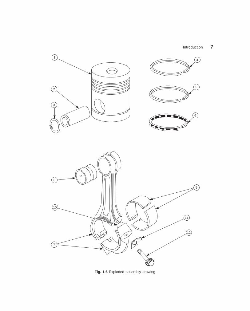
In some cases, exploded pictorial views are supplied to meet instruction manual requirements.These drawings generally find a place in the parts list section of a company instruction manual.Figure 1.6 shows drawings of this type which may be easily understood even by those with lessexperience in the reading of drawings; because in these exploded views, the parts are positionedin the sequence of assembly, but separated from each other.
������#�$�%� �������� ���������
It is very difficult to understand the operating principles of complicated machinery, merelyfrom the assembly drawings. Schematic representation of the unit facilitates easy understandingof its operating principle. It is a simplified illustration of the machine or of a system, replacingall the elements, by their respective conventional representations. Figure 1.7 shows theschematic representation of a gearing diagram.
������&����%���$%�"������
Rough castings and forgings are sent to the machine shop for finishing operation (Fig. 1.8).Since the machinist is not interested in the dimensions and information of the previous stages,a machine shop drawing frequently gives only the information necessary for machining. Basedon the same principle, one may have forge shop drawing, pattern shop drawing, sheet metaldrawing, etc.

6 Machine Drawing
dharmd:\N-Design\Des1-1.pm5 Seventh Print
18
17
BHARATH1
2
4
3
5
6
8
79
10
11
13
14
15
12
16
Speed change lever (1)
Depth adjusting knob (2)
Mech. feed engagement lever (3)
Hand feed lever (4)
Feed change knob (5)
Switch for tapping (6)
Gear shifting lever (7)
Main switch (8)
Lamp switch (9)
Selector switch (10)
Forward/reverse switch (11)
Pilot lamp (12)
Feed disengagement push button (13)
Start push button (14)
Emergency stop (15)
Elevating handle (16)
Clamping handle (17)
Supply inlet (18)
Fig. 1.5 Assembly drawing for instruction manuals
Introduction 7
dharmd:\N-Design\Des1-1.pm5 Seventh Print
3
2
8
14
5
6
10
7
9
11
12
Fig. 1.6 Exploded assembly drawing

8 Machine Drawing
dharmd:\N-Design\Des1-1.pm5 Seventh Print
678910
5 1 2 3 4
10
9
8
7
6
5
4
3
2
1
No.
Shaft
Change-over lever
Disk clutch
Worm wheel
Worm
Shoe brake
Herringbone gear
Bearing
Elastic coupling
Electric motor
Name
1
2
2
2
2
2
3
6
2
2
Qty
Fig. 1.7 Schematic assembly drawing
A
f14
0
f10
0
20
85
5
6×6 NECK
( , )Ñ
Casting size
CORED HOLE,
DIA 38
B
f41
–0.0
0+
0.10
M76
4 HOLES DIA12, DIA16 C’BORE
10 DEEP EQUI-SP
f 0 . 1 A B
R5
f70
–0.1
0+
0.00
Fig. 1.8 Machine shop drawing
Introduction 9
dharmd:\N-Design\Des1-1.pm5 Seventh Print
�������'�(�����������
When new machines or devices are invented, patent drawings come into existence, to illustrateand explain the invention. These are pictorial drawings and must be self-explanatory. It isessential that the patent drawings are mechanically correct and include complete illustrationsof every detail of the invention. However, they are not useful for production purposes. Thesalient features on the drawing are numbered for identification and complete description.
THEORY QUESTIONS
1.1 Classify the various types of drawings used in mechanical engineering field.1.2 Explain the term ‘‘Machine drawing’’.1.3 Define the term ‘‘Production drawing’’.1.4 Differentiate between machine drawing and production drawing.1.5 What is an assembly drawing ?1.6 List out the various types of assembly drawings.1.7 What is meant by a detailed assembly drawing ?1.8 What is a sub-assembly drawing ?1.9 What is an exploded assembly drawing and where is it used ?
1.10 Distinguish between the drawings for catalogues and instruction manuals.1.11 What is meant by a schematic assembly drawing and when is it preferred ?1.12 What is a machine shop drawing and how is it different from machine drawing ?1.13 What are patent drawings and how are they prepared ?

A4
A3
A2
A1
A0
10
2������������� �����
��� ����������
Engineering drawings are to be prepared on standard size drawing sheets. The correct shapeand size of the object can be visualised from the understanding of not only the views of it butalso from the various types of lines used, dimensions, notes, scale, etc. To provide the correctinformation about the drawings to all the people concerned, the drawings must be prepared,following certain standard practices, as recommended by Bureau of Indian Standards (BIS).
��� �� ���� �����
Engineering drawings are prepared on drawing sheetsof standard sizes. The use of standard size sheet, savespaper and facilitates convenient storage of drawings.
����� ����������
The basic principles involved in arriving at the sizesof drawing sheets are:
(a) X : Y = 1 : 2 , (b) XY = 1where X and Y are the sides of the sheet. For areference size A0 (Table 2.1) having a surface area of1 m2, X = 841 mm and Y = 1189 mm. The successiveformat sizes are obtained either by halving along thelength or doubling along the width, the areas beingin the ratio 1:2 (Fig. 2.1).
����� ��������� � ! �����
The original drawing should be made on the smallestsheet, permitting the necessary clarity and resolution.The preferred sizes according to ISO-A series (Firstchoice) of the drawing sheets are given in Table 2.1.When sheets of greater length are needed, specialelongated sizes (Second choice) are used (Table 2.2).These sizes are obtained by extending the shortersides of format of the ISO-A series to lengths that aremultiples of the shorter sides of the chosen basicformat.
Fig. 2.1 Drawing sheet formats
*Material for this chapter has been taken from BIS; SP–46: 1988.
Principles of Drawing 11
dharmd:\N-Design\Des2-1.pm5 Seventh Print
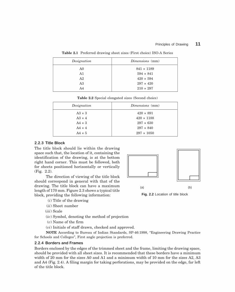
Table 2.1 Preferred drawing sheet sizes (First choice) ISO-A Series
Designation Dimensions (mm)
A0 841 × 1189A1 594 × 841A2 420 × 594A3 297 × 420A4 210 × 297
Table 2.2 Special elongated sizes (Second choice)
Designation Dimensions (mm)
A3 × 3 420 × 891A3 × 4 420 × 1188A4 × 3 297 × 630A4 × 4 297 × 840A4 × 5 297 × 1050
����" ���#�$# %&
The title block should lie within the drawingspace such that, the location of it, containing theidentification of the drawing, is at the bottomright hand corner. This must be followed, bothfor sheets positioned horizontally or vertically(Fig. 2.2).
The direction of viewing of the title blockshould correspond in general with that of thedrawing. The title block can have a maximumlength of 170 mm. Figure 2.3 shows a typical titleblock, providing the following information:
(i) Title of the drawing(ii) Sheet number
(iii) Scale(iv) Symbol, denoting the method of projection(v) Name of the firm
(vi) Initials of staff drawn, checked and approved.NOTE According to Bureau of Indian Standards, SP-46:1998, ‘‘Engineering Drawing Practice
for Schools and Colleges’’, First angle projection is preferred.
����' $ ()�(���)�(�*��
Borders enclosed by the edges of the trimmed sheet and the frame, limiting the drawing space,should be provided with all sheet sizes. It is recommended that these borders have a minimumwidth of 20 mm for the sizes A0 and A1 and a minimum width of 10 mm for the sizes A2, A3and A4 (Fig. 2.4). A filing margin for taking perforations, may be provided on the edge, far leftof the title block.
(a) (b)
Fig. 2.2 Location of title block

12 Machine Drawing
dharmd:\N-Design\Des2-1.pm5 Seventh Print
DRN
CHD
APPD
NAME DATE MATERIAL TOLERANCE FINISH
170
PROJECTION LEGALOWNER
TITLE
SCALE IDENTIFICATION NUMBER
65
Fig. 2.3 Details in title block
Trimming mark
1 2 3
A
4 5 6
A
B
C
D
1 2 3 4 5 6
Metric reference graduation
Orientation mark
Frame
Centring mark
Drawing space
Title blockD
Edge
Minimum width(20 mm for A0 and A110 mm for A2, A3 and A4)
Grid reference Border
Fig. 2.4 Drawing sheet layout
����+����(���,�(&�
Four centring marks may be provided, in order to facilitate positioning of the drawing whenreproduced or microfilmed. Two orientation marks may be provided to indicate the orientationof the drawing sheet on the drawing board (Fig. 2.4).
����������������� ����������
It is recommended to provide a figure-less metric reference graduation, with a minimum lengthof 100 mm and divided into 10 intervals on all the drawing sheets (Fig. 2.4) which are intendedto be microfilmed. The metric reference graduation may be disposed symmetrically about acentring mark, near the frame at the border, with a minimum width of 5 mm.
Principles of Drawing 13
dharmd:\N-Design\Des2-1.pm5 Seventh Print
����-�(�)��!�(��%��.���*/0 ����1
The provision of a grid reference system is recommended for all the sizes, in order to permiteasy location on the drawing of details, additions, modifications, etc. The number of divisionsshould be divisible by two and be chosen in relation to the complexity of the drawing. It isrecommended that the length of any side of the grid should not be less than 25 mm and notmore than 75 mm. The rectangles of the grid should be referenced by means of capital lettersalong one edge and numerals along the other edge, as shown in Fig. 2.4. The numbering directionmay start at the sheet corner opposite to the title block and be repeated on the opposite sides.
����2�(�**���,�(&�
Trimming marks may be provided in the borders at the four corners of the sheet, in order tofacilitate trimming. These marks may be in the form of right angled isosceles triangles or twoshort strokes at each corner (Fig. 2.4).
��" �� ���
Scale is the ratio of the linear dimension of an element of an object as represented in thedrawing, to the real linear dimension of the same element of the object itself. Wherever possible,it is desirable to make full size drawings, so as to represent true shapes and sizes. If this is notpracticable, the largest possible scale should be used. While drawing very small objects, suchas watch components and other similar objects, it is advisable to use enlarging scales.
��"�� ��������� �
The complete designation of a scale should consist of the word Scale, followed by the indicationof its ratio as:
SCALE 1 : 1 for full size,SCALE × : 1 for enlarged scales,SCALE 1 : × for reduced scales.The designation of the scale used on the drawing should be shown in the title block.
��"�� ��% **��)�)�%�#��
The recommended scales for use on technical drawings are given in Table 2.3. The scale andthe size of the object in turn, will decide the size of the drawing.
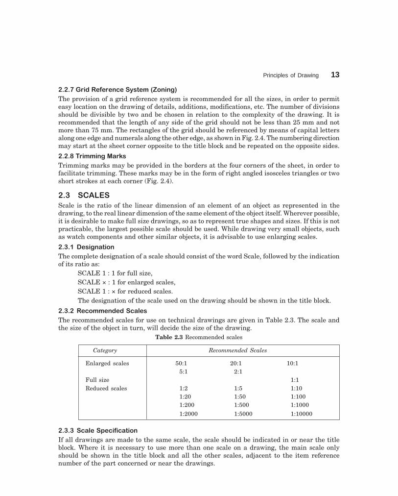
Table 2.3 Recommended scales
Category Recommended Scales
Enlarged scales 50:1 20:1 10:15:1 2:1
Full size 1:1Reduced scales 1:2 1:5 1:10
1:20 1:50 1:1001:200 1:500 1:1000
1:2000 1:5000 1:10000
��"�" �%�#��3�%�!�%��� �
If all drawings are made to the same scale, the scale should be indicated in or near the titleblock. Where it is necessary to use more than one scale on a drawing, the main scale onlyshould be shown in the title block and all the other scales, adjacent to the item referencenumber of the part concerned or near the drawings.

14 Machine Drawing
dharmd:\N-Design\Des2-1.pm5 Seventh Print
��' �����
Lines of different types and thicknesses are used for graphical representation of objects. Thetypes of lines and their applications are shown in Table 2.4. Typical applications of differenttypes of lines are shown in Figs. 2.5 and 2.6.
Table 2.4 Types of lines and their applications
Line Description General Applications
Continuous thick A1 Visible outlines
Continuous thin B1 Imaginary lines of intersection(straight or curved) B2 Dimension lines
B3 Projection linesB4 Leader linesB5 Hatching linesB6 Outlines of revolved sections in placeB7 Short centre lines
Continuous thin, free-hand C1 Limits of partial or interrupted viewsand sections, if the limit is not achain thin
Continuous thin (straight) D1 Line (see Fig. 2.5)with zigzags
Dashed thick E1 Hidden outlines
Chain thin G1 Centre linesG2 Lines of symmetryG3 Trajectories
Chain thin, thick at ends H1 Cutting planesand changes of direction
Chain thick J1 Indication of lines or surfaces to whicha special requirement applies
Chain thin, double-dashed K1 Outlines of adjacent partsK2 Alternative and extreme positions of
movable parts
K3 Centroidal lines
B
C
D
A
E
G
H
J
K

Principles of Drawing 15
dharmd:\N-Design\Des2-1.pm5 Seventh Print
D1
K1
B1D1
B6
J1 G1
A1
B4
G1
E1
G3
B2
G2
K2
B2
B3
B5
B7
YY – Y
Y
Fig. 2.5 Applications of lines
K3
C1
Fig. 2.6 Applications of lines
��'�� ���%&���� !�����
Two thicknesses of lines are used in draughting practice. The ratio of the thick to thin lineshould not be less than 2:1. The thickness of lines should be chosen according to the size andtype of the drawing from the following range:
0.18, 0.25, 0.35, 0.5, 0.7, 1, 1.4 and 2It is recommended that the space between two parallel lines, including hatching, should
never be less than 0.7 mm.

16 Machine Drawing
dharmd:\N-Design\Des2-1.pm5 Seventh Print
��'�� ()�( ! �(� (��. !� ��%�)��������
When two or more lines of different types coincide, the following order of priority should beobserved:
(i) Visible outlines and edges (Continuous thick lines, type A),(ii) Hidden outlines and edges (Dashed line, type E or F),
(iii) Cutting planes (Chain thin, thick at ends and changes of cutting planes, type H),(iv) Centre lines and lines of symmetry (Chain thin line, type G),(v) Centroidal lines (Chain thin double dashed line, type K),
(vi) Projection lines (Continuous thin line, type B).The invisible line technique and aixs representation should be followed as per the
recommendations given in Table 2.5.Table 2.5A Invisible lines
Instructions Correct Incorrect
Begin with a dash, not with aspace
Dashes intersect without a gapbetween them
Three dashes meet at theintersection point
As a continuation of a visibleline/arc, begin with space
Invisible arcs begin with a dash
Small arcs may be made solid
Two arcs meet at the point of
tangency

Principles of Drawing 17
dharmd:\N-Design\Des2-1.pm5 Seventh Print
Table 2.5B Axis lines
Instructions Correct Incorrect
Axis line starts andends with a longer dash
Two axes intersectwith longer dashes
Axis extends theboundary with a longer dash
��'�" ��(*����� � ! ���)�(�����
A leader is a line referring to a feature (dimension, object, outline, etc.).Leader lines should terminate (Fig. 2.7),(a) with a dot, if they end within the outlines of an object,(b) with an arrow head, if they end on the outline of an object,(c) without dot or arrow head, if they end on a dimension line.
(a) (b) (c)
Fig. 2.7 Termination of leader lines
It is common practice to omit hidden lines in an assembled view, when their use tends toconfuse an already complex drawing or when the feature is sufficiently clear in another view;but it is not advisable for a beginner to do the same and he will have to show the hidden linesin his drawing practice.

18 Machine Drawing
dharmd:\N-Design\Des2-1.pm5 Seventh Print
��+ ���������
The essential features of lettering on technical drawings are, legibility, uniformity and suitabilityfor microfilming and other photographic reproductions. In order to meet these requirements,the characters are to be clearly distinguishable from each other in order to avoid any confusionbetween them, even in the case of slight mutilations. The reproductions require the distancebetween two adjacent lines or the space between letters to be at least equal to twice the linethickness (Fig. 2.8). The line thickness for lower case and capital letters shall be the same inorder to facilitate lettering.
IS0 81 ejAfR
d
h
a e
h
c
a
b
Fig. 2.8 Dimensions of lettering
��+�� ��*���� ��
The following specifications are given for the dimensions of letters and numerals:(i) The height of capital letters is taken as the base of dimensioning (Tables 2.6 and 2.7).
(ii) The two standard ratios for d/h, 1/14 and 1/10 are the most economical, as theyresult in a minimum number of line thicknesses.
(iii) The lettering may be inclined at 15° to the right, or may be vertical.
Table 2.6 Lettering A (d = h/14)
Characteristic Ratio Dimensions, (mm)
Lettering height h (14/14)h 2.5 3.5 5 7 10 14 20(Height of capitals)
Height of lower-case letters c (10/14)h — 2.5 3.5 5 7 10 14(without stem or tail)
Spacing between characters a (2/14)h 0.35 0.5 0.7 1 1.4 2 2.8
Minimum spacing of base lines b (20/14)h 3.5 5 7 10 14 20 28
Minimum spacing between words e (6/14)h 1.05 1.5 2.1 3 4.2 6 8.4
Thickness of lines d (1/14)h 0.18 0.25 0.35 0.5 0.7 1 1.4
NOTE The spacing between two characters may be reduced by half, if this gives a better viusal effect asfor example LA, TV; it then equals the line thickness.

Principles of Drawing 19
dharmd:\N-Design\Des2-1.pm5 Seventh Print
j
A B C D E F GH IJKLMN
OP Q R S T U V W X Y Z
bc d e f gh k l mn o p
q r s t u v w x y z
[( ;"–=+× %& [(
0123 4 5 6 789 I V X 75°
c i
Fig. 2.9 Inclined lettering
Table 2.7 Lettering B (d = h/10)
Characteristic Ratio Dimensions, (mm)
Lettering height h (10/10)h 2.5 3.5 5 7 10 14 20(Height of capitals)
Height of lower-case letters c (7/10)h — 2.5 3.5 5 7 10 14(without stem or tail)
Spacing between characters a (2/10)h 0.5 0.7 1 1.4 2 2.8 4
Minimum spacing of base lines b (14/10)h 3.5 5 7 10 14 20 28
Minimum spacing between words e (6/14)h 1.5 2.1 3 4.2 6 8.4 12
Thickness of lines d (1/10)h 0.25 0.35 0.5 0.7 1 1.4 2
Figures 2.9 and 2.10 show the specimen letters of type A, inclined and vertical and aregiven only as a guide to illustrate the principles mentioned above.
��4 �������
In order to show the inner details of a machine component, the object is imagined to be cut bya cutting plane and the section is viewed after the removal of cut portion. Sections are made byat cutting planes and are designated by capital letters and the direction of viewing is indicatedby arrow marks.

20 Machine Drawing
dharmd:\N-Design\Des2-1.pm5 Seventh Print
c
AB C D E FGH IJKLMN
O P Q R ST U V W X Y Z
bc d e f gh k mnop
q r s t u v w x y z
[ ( " –=+× % & [(
0123 4 5 6 7 8 9 I V X
l
Fig. 2.10 Vertical lettering
��4�� ���%���� ! ��%�� ��
Hatching is generally used to show areas of sections. The simplest form of hatching is generallyadequate for the purpose, and may be continuous thin lines (type B) at a convenient angle,preferably 45°, to the principal outlines or lines of symmetry of the sections (Fig. 2.11).
Fig. 2.11 Preferred hatching angles
Separate areas of a section of the same component shall be hatched in an identicalmanner. The hatching of adjacent components shall be carried out with different directions orspacings (Fig 2.12 a). In case of large areas, the hatching may be limited to a zone, followingthe contour of the hatched area (Fig. 2.12 b).
Where sections of the same part in parallel planes are shown side by side, the hatchingshall be identical, but may be off-set along the dividing line between the sections (Fig. 2.13).Hatching should be interrupted when it is not possible to place inscriptions outside the hatchedarea (Fig. 2.14).

Principles of Drawing 21
dharmd:\N-Design\Des2-1.pm5 Seventh Print
X – X
X X
(a) (b)
Fig. 2.12 Hatching of adjacent components
X
X
X – X
5050
Fig. 2.13 Sectioning along two Fig. 2.14 Hatching interrupted parallel planes for dimensioning
��4�� �5������#����
The cutting plane(s) should be indicated by means of type Hline. The cutting plane should be identified by capital lettersand the direction of viewing should be indicated by arrows.The section should be indicated by the relevant designation(Fig. 2.15).
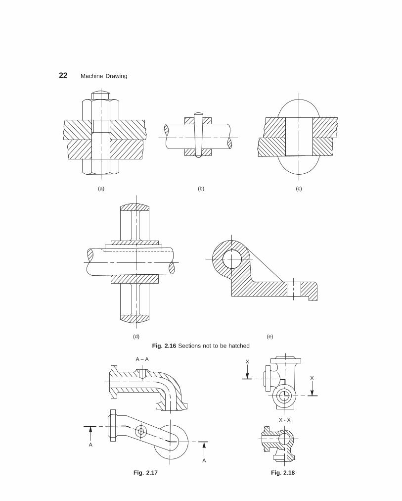
In principle, ribs, fasteners, shafts, spokes of wheelsand the like are not cut in longitudinal sections and thereforeshould not be hatched (Fig. 2.16).
Figure 2.17 represents sectioning in two parallel planesand Fig. 2.18, that of sectioning in three continuous planes.
Fig. 2.15 Cutting plane indication
22 Machine Drawing
dharmd:\N-Design\Des2-1.pm5 Seventh Print
(a) (b) (c)
(d) (e)
Fig. 2.16 Sections not to be hatched
A – A
A
A
X
X
X - X
Fig. 2.17 Fig. 2.18

Principles of Drawing 23
dharmd:\N-Design\Des2-1.pm5 Seventh Print
Sectioning in two intersecting planes, in which one is shown revolved into plane ofprojection, as shown in Fig. 2.19.
In case of parts of revolution, containing regularly spaced details that require to beshown in section, but are not situated in the cutting plane; such details may be depicted byrotating them into the cutting plane (Fig. 2.20).
��4�" ��6 #6�) (��* 6�)��%�� �
Cross sections may be revolved in the relevant view or removed. When revolved in the relevantview, the outline of the section should be shown with continuous thin lines (Fig. 2.21). Whenremoved, the outline of the section should be drawn with continuous thick lines. The removedsection may be placed near to and connected with the view by a chain thin line (Fig. 2.22 a) orin a different position and identified in the conventional manner, as shown in Fig. 2.22 b.
A
A
A–A X–X
X
X
Fig. 2.19 Fig. 2.20
Fig. 2.21 Revolved section
A
A
A–A
(b)(a)
Fig. 2.22 Removed section

24 Machine Drawing
dharmd:\N-Design\Des2-1.pm5 Seventh Print
��4�' ��#!��%�� �
Symmetrical parts may be drawn, half in plain view and half insection (Fig 2.23).
��4�+ � %�#��%�� �
A local section may be drawn if half or fullsection is not convenient. The local break maybe shown by a continuous thin free hand line(Fig. 2.24).
��4�4 ((����*��� ! �5%%����6���%�� ��
Successive sections may be placed separately, with designations for both cutting planes andsections (Fig. 2.25) or may be arranged below the cutting planes.
A
A
B
BD
DC
C
A–A B–B C–C D–D
Fig. 2.25 Successive sections
��- ��7����� � ��������� ���
Certain draughting conventions are used to represent materials in section and machine elementsin engineering drawings.
��-�� ,���(��#�
As a variety of materials are used for machine components in engineering applications, it ispreferable to have different conventions of section lining to differentiate between variousmaterials. The recommended conventions in use are shown in Fig.2.26.
��-�� ,�%����� *3 �����
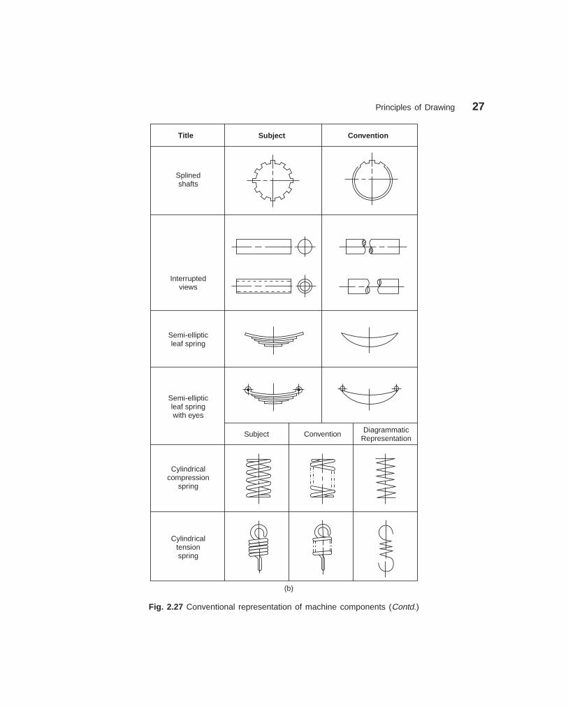
When the drawing of a component in its true projection involves a lot of time, its conventionmay be used to represent the actual component. Figure 2.27 shows typical examples ofconventional representaion of various machine components used in engineering drawing.
Fig. 2.24 Local section
Fig. 2.23 Half section

Principles of Drawing 25
dharmd:\N-Design\Des2-1.pm5 Seventh Print
Type Convention Material
Metals
Glass
Packing andInsulating material
Liquids
Wood
Concrete
Steel, Cast Iron, Copper and itsAlloys, Aluminium and its Alloys,
etc.
Lead, Zinc, Tin, White-metal, etc.
Glass
Porcelain, Stoneware, Marble,Slate, etc.
Asbestos, Fibre, Felt, Syntheticresin products, Paper, Cork,
Linoleum, Rubber, Leather, Wax,Insulating and Filling materials, etc.
Water, Oil, Petrol, Kerosene, etc.
Wood, Plywood, etc.
A mixture of Cement, Sand andGravel
Fig. 2.26 Conventional representation of materials
��2 ��,��������
A drawing of a component, in addition to providing complete shape description, must alsofurnish information regarding the size description. These are provided through the distancesbetween the surfaces, location of holes, nature of surface finsih, type of material, etc. Theexpression of these features on a drawing, using lines, symbols, figures and notes is calleddimensioning.
��2�� ����(�#�(��%�3#��
Dimension is a numerical value expressed in appropriate units of measurment and indicatedon drawings, using lines, symbols, notes, etc., so that all features are completely defined.

26 Machine Drawing
dharmd:\N-Design\Des2-1.pm5 Seventh Print
Fig. 2.27 Conventional representation of machine components (Contd.)
Principles of Drawing 27
dharmd:\N-Design\Des2-1.pm5 Seventh Print
Title Subject Convention
Splinedshafts
Interruptedviews
Semi-ellipticleaf spring
Semi-ellipticleaf springwith eyes
Cylindricalcompression
spring
Cylindricaltensionspring
Subject Convention DiagrammaticRepresentation
(b)
Fig. 2.27 Conventional representation of machine components (Contd.)

28 Machine Drawing
dharmd:\N-Design\Des2-1.pm5 Seventh Print
Title Convention
Spur gear
Bevel gear
Worm wheel
Worm
Fig. 2.27 Conventional representation of machine components
1. As far as possible, dimensions should be placed outside the view.2. Dimensions should be taken from visible outlines rather than from hidden lines.3. Dimensioning to a centre line should be avoided except when the centre line passes
through the centre of a hole.4. Each feature should be dimensioned once only on a drawing.5. Dimensions should be placed on the view or section that relates most clearly to the
corresponding features.6. Each drawing should use the same unit for all dimensions, but without showing the
unit symbol.7. No more dimensions than are necessary to define a part should be shown on a drawing.8. No features of a part should be defined by more than one dimension in any one direction.
��2�� ,��� ) ! �8�%5�� �
The elements of dimensioning include the projection line, dimension line, leader line, dimensionline termination, the origin indication and the dimension itself. The various elements of

Principles of Drawing 29
dharmd:\N-Design\Des2-1.pm5 Seventh Print
dimensioning are shown in Figs. 2.28 and 2.29. The following are some of the principles to beadopted during execution of dimensioning:
Leader line
2 45°´
Origin indication Dimension lineTermination (Arrow head)
4500
3500
1500
Projection line
Value of the dimension
Fig. 2.28 Elements of dimensioning
Dimension line
Value of the dimension
4240
Projection line
Termination (Oblique stroke)
Fig. 2.29
1. Projection and dimension lines should be drawn as thin continuous lines.2. Projection lines should extend slightly beyond the respective dimension lines.3. Projection lines should be drawn perpendicular to the feature being dimensioned.
Where necessary, they may be drawn obliquely, but parallel to each other (Fig. 2.30). However,they must be in contact with the feature.
4. Projection lines and dimension lines should not cross each other, unless it is unavoidable(Fig. 2.31).
5. A dimension line should be shown unbroken, even where the feature to which itrefers, is shown broken (Fig. 2.32).
6. A centre line or the outline of a part should not be used as a dimension line, but maybe used in place of projection line (Fig. 2.31).
28 12
6
13
21
16 18
26
Fig. 2.30 Fig. 2.31 Fig. 2.32

30 Machine Drawing
dharmd:\N-Design\Des2-1.pm5 Seventh Print
Arrow head
Oblique stroke
Origin indication
��2�" ��(*����� ���)(������)�%��� �
Dimension lines should show distinct termination, in the form ofarrow heads or oblique strokes or where applicable, an originindication. Two dimension line terminations and an origin indicationare shown in Fig. 2.33. In this,
1. the arrow head is drawn as short lines, having an includedangle of 15°, which is closed and filled-in.
2. the oblique stroke is drawn as a short line, inclined at 45°.3. the origin indication is drawn as a small open circle of
approximately 3 mm in diameter.The size of the terminations should be proportionate to the size of the drawing on which
they are used. Where space is limited, arrow head termination may be shown outside theintended limits of the dimension line that is extended for that purpose. In certain other cases,an oblique stroke or a dot may be substituted (Fig. 2.34).
Where a radius is dimensioned, only one arrow head termination, with its point on thearc end of the dimension line, should be used (Fig. 2.35). However, the arrow head terminationmay be either on the inside or outside of the feature outline, depending upon the size of feature.
30
30
20 10
20
1010
1010
R 6.5R50 R30
0
R25
0
Fig. 2.34 Fig. 2.35
��2�' ,��� )� ! ��)�%�������*���� ��
Dimensions should be shown on drawings in characters of sufficient size, to ensure completelegibility. They should be placed in such a way that they are not crossed or separated by anyother line on the drawing. Dimensions should be indicated on a drawing, according to one ofthe following two methods. However, only one method should be used on any one drawing.
METHOD–1 (Aligned System)
Dimensions should be placed parallel to their dimension lines and preferably near the middle,above and clear-off the dimension line (Fig. 2.36). An exception may be made where super-imposed running dimensions are used (Fig. 2.44 b)
Dimensions may be written so that they can be read from the bottom or from the rightside of the drawing. Dimensions on oblique dimension lines should be oriented as shown inFig. 2.37. Angular dimensions may be oriented as shown in Fig. 2.38.
Fig. 2.33

Principles of Drawing 31
dharmd:\N-Design\Des2-1.pm5 Seventh Print
15 f12
f8
30
70
39
20 20
20
20
20
20
20
20
20
20
20
20
60°
30°
60°
60° 60°
60°30°
Fig. 2.36 Fig. 2.37 Oblique dimensioning Fig. 2.38 Angular dimensioning
METHOD–2 (Uni-directional System)
Dimensons should be indicated so that they can be read from the bottom of the drawing only.Non-horizontal dimension lines are interrupted, preferably near the middle, for insertion ofthe dimension (Fig. 2.39).
Angular dimensions may be oriented as in Fig. 2.40.
70
30303939
60°60°
30°30°
60°60°
60°60°
30°30°
60°60°60°60°
Fig. 2.39 Fig. 2.40 Angular dimensioning
Dimensions can be, (i) above the extension of thedimension line, beyond one of the terminations, wherespace is limited (Fig. 2.34) or (ii) at the end of a leaderline, which teminates on a dimension line, that is too shortto permit normal dimension placement (Fig. 2.34) or (iii)above a horizontal extension of a dimension line, wherespace does not allow placement at the interruption of anon-horizontal dimension line (Fig. 2.41). Values ofdimensions, out of scale (except where break lines areused) should be underlined as shown in Fig. 2.41.
The following indications (symbols) are used with dimensions to reveal the shapeidentification and to improve drawing interpretation. The symbol should precede the dimensions(Fig. 2.42).
φ : Diameter Sφ : Spherical diameter R : Radius SR : Spherical radius : Square
Fig. 2.41

32 Machine Drawing
dharmd:\N-Design\Des2-1.pm5 Seventh Print
160 70 200 30
150
100
Fig. 2.43 Chain dimensioning
f30
f40
(a)
R10R15
(b)
f40
(c)
SR17
SR
60
(d) (e)
S 50f
Fig. 2.42 Shape identification symbols
��2�+ ((����*��� ! ��*���� ��
The arrangement of dimensions on a drawing must indicate clearly the design purpose. Thefollowing are the ways of arranging the dimensions.
������������� ������
Chains of single dimensions should be used only wherethe possible accumulation of tolerances does not endangerthe functional requirement of the part (Fig. 2.43).
���������������� ������
In parallel dimensoning, a number of dimension lines,parallel to one another and spaced-out are used. Thismethod is used where a number of dimensions have acommon datum feature (Fig. 2.44 a).
�������������� �������������� ������
These are simplified parallel dimensons and may be used where there are spacelimitations (Fig. 2.44 b).
150
420
640
(a)
0
(b)
150
420
640
Fig. 2.44 Parallel dimensioning
������������ ������ ������
These are the result of simultaneous use of chain and parallel dimensions (Fig. 2.45).
Principles of Drawing 33
dharmd:\N-Design\Des2-1.pm5 Seventh Print
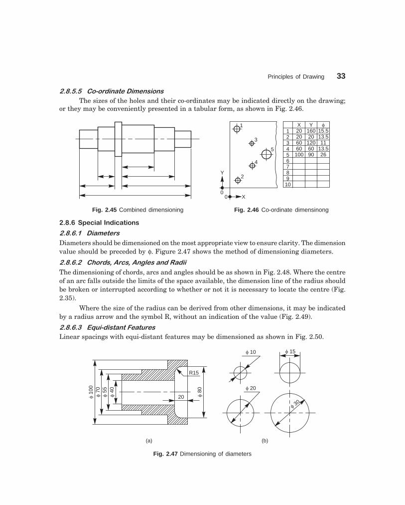
��������������������� ������
The sizes of the holes and their co-ordinates may be indicated directly on the drawing;or they may be conveniently presented in a tabular form, as shown in Fig. 2.46.
00
X
Y
1
3
5
4
2
X20206060
100
Y16020
1206090
f15.513.511
13.526
123456789
10
Fig. 2.45 Combined dimensioning Fig. 2.46 Co-ordinate dimensinong
��2�4 �3�%��#��)�%��� ��
����������� �����
Diameters should be dimensioned on the most appropriate view to ensure clarity. The dimensionvalue should be preceded by φ. Figure 2.47 shows the method of dimensioning diameters.
���������������� �!�"� �!�����������
The dimensioning of chords, arcs and angles should be as shown in Fig. 2.48. Where the centreof an arc falls outside the limits of the space available, the dimension line of the radius shouldbe broken or interrupted according to whether or not it is necessary to locate the centre (Fig.2.35).
Where the size of the radius can be derived from other dimensions, it may be indicatedby a radius arrow and the symbol R, without an indication of the value (Fig. 2.49).
����������#$��������%������
Linear spacings with equi-distant features may be dimensioned as shown in Fig. 2.50.
f10
0f
70f
55f
40
R15
20 f80
(a)
f 10 f 15
f 20
(b)
f 30
Fig. 2.47 Dimensioning of diameters

34 Machine Drawing
dharmd:\N-Design\Des2-1.pm5 Seventh Print
12
15
M10
M1020
100
105
42°
Fig. 2.48 Dimensioning of chords, Fig. 2.50 Dimensioning equi-distant features arcs and angles
���������� &�����������������'�
Chamfers may be dimensioned as shown in Fig. 2.51 and countersunks, as shown in Fig. 2.52.
2×45° 2×45°
or
(b)
(a)
or
2×45°
2×45°
f14
90°
90°
or
3.5
Fig. 2.51 Dimensioning chamfers Fig. 2.52 Dimensioning countersunks
���������"��(�)�����
Screw threads are always specified with properdesignation. The nominal diameter is preceded by theletter M. The useful length of the threaded portion onlyshould be dimenioned as shown in Fig. 2.53. Whiledimensioning the internal threads, the length of thedrilled hole should also be dimensioned (Fig. 2.53).
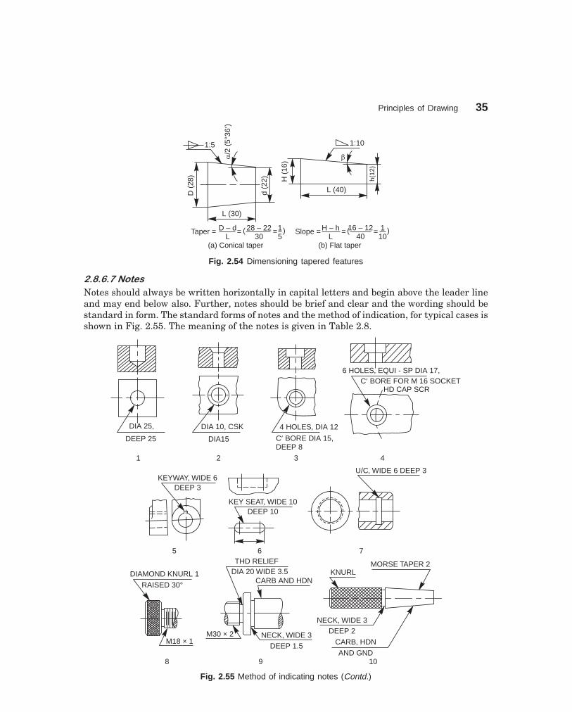
��������)������%������
Tapered features are dimensioned, either by specifying the diameters at either end and thelength, or the length, one of the diameters and the taper or the taper angle (Fig. 2.54 a).
A slope or flat taper is defined as the rise per unit length and is dimensioned by the ratioof the difference between the heights to its length (Fig. 2.54 b).
Fig. 2.49 Dimensioning of radius
Fig. 2.53 Dimensioning screw threads
15 5 × 18 (= 90)
R
50
16
Principles of Drawing 35
dharmd:\N-Design\Des2-1.pm5 Seventh Print
L (30)
D(2
8)
d(2
2)
a¢
/2(5
°36
)
1:5
Taper = =D – dL
15
28 – 2230
=( )
(a) Conical taper (b) Flat taper
Slope = = =H – hL
16 – 1240
110
( )
1:10
H(1
6)
h(12
)
L (40)
b
Fig. 2.54 Dimensioning tapered features
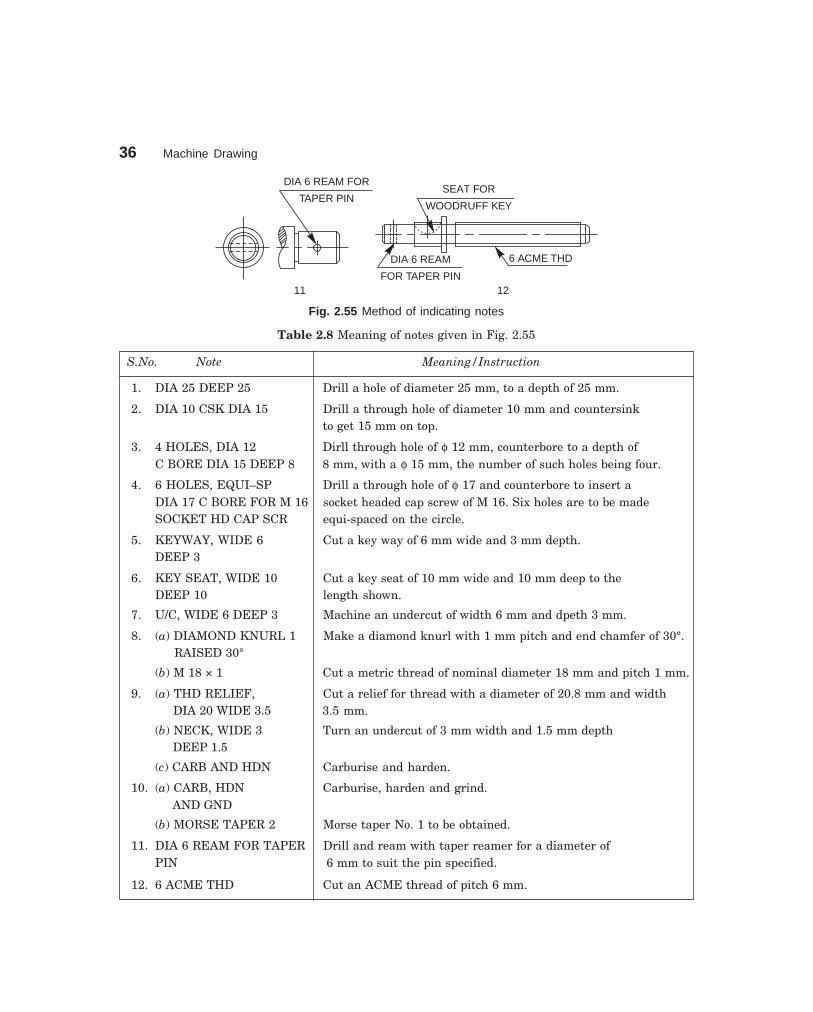
������*�+����
Notes should always be written horizontally in capital letters and begin above the leader lineand may end below also. Further, notes should be brief and clear and the wording should bestandard in form. The standard forms of notes and the method of indication, for typical cases isshown in Fig. 2.55. The meaning of the notes is given in Table 2.8.
DIA 25,DIA 25,
DEEP 25DEEP 25
1
DIA 10, CSKDIA 10, CSK
DIA15DIA15
2
4 HOLES, DIA 124 HOLES, DIA 12
C BORE DIA 15,DEEP 8
¢
3
6 HOLES, EQUI - SP DIA 17,C BORE FOR M 16 SOCKET¢
HD CAP SCR
4
KEYWAY, WIDE 6DEEP 3
5
KEY SEAT, WIDE 10DEEP 10
6 7
U/C, WIDE 6 DEEP 3
M18 × 1
DIAMOND KNURL 1
RAISED 30°
NECK, WIDE 3DEEP 1.5
M30 × 2
THD RELIEFDIA 20 WIDE 3.5
CARB AND HDN
8 9
KNURLMORSE TAPER 2
CARB, HDN
AND GND10
NECK, WIDE 3DEEP 2
Fig. 2.55 Method of indicating notes (Contd.)
36 Machine Drawing
dharmd:\N-Design\Des2-1.pm5 Seventh Print
DIA 6 REAM FOR
TAPER PIN
11
6 ACME THD
12
SEAT FOR
WOODRUFF KEY
DIA 6 REAM
FOR TAPER PIN
Fig. 2.55 Method of indicating notes
Table 2.8 Meaning of notes given in Fig. 2.55
S.No. Note Meaning/Instruction
1. DIA 25 DEEP 25 Drill a hole of diameter 25 mm, to a depth of 25 mm.
2. DIA 10 CSK DIA 15 Drill a through hole of diameter 10 mm and countersinkto get 15 mm on top.
3. 4 HOLES, DIA 12 Dirll through hole of φ 12 mm, counterbore to a depth ofC BORE DIA 15 DEEP 8 8 mm, with a φ 15 mm, the number of such holes being four.
4. 6 HOLES, EQUI–SP Drill a through hole of φ 17 and counterbore to insert aDIA 17 C BORE FOR M 16 socket headed cap screw of M 16. Six holes are to be madeSOCKET HD CAP SCR equi-spaced on the circle.
5. KEYWAY, WIDE 6 Cut a key way of 6 mm wide and 3 mm depth.DEEP 3
6. KEY SEAT, WIDE 10 Cut a key seat of 10 mm wide and 10 mm deep to theDEEP 10 length shown.
7. U/C, WIDE 6 DEEP 3 Machine an undercut of width 6 mm and dpeth 3 mm.
8. (a) DIAMOND KNURL 1 Make a diamond knurl with 1 mm pitch and end chamfer of 30°. RAISED 30°
(b) M 18 × 1 Cut a metric thread of nominal diameter 18 mm and pitch 1 mm.
9. (a) THD RELIEF, Cut a relief for thread with a diameter of 20.8 mm and width DIA 20 WIDE 3.5 3.5 mm.
(b) NECK, WIDE 3 Turn an undercut of 3 mm width and 1.5 mm depth DEEP 1.5
(c) CARB AND HDN Carburise and harden.
10. (a) CARB, HDN Carburise, harden and grind. AND GND
(b) MORSE TAPER 2 Morse taper No. 1 to be obtained.
11. DIA 6 REAM FOR TAPER Drill and ream with taper reamer for a diameter ofPIN 6 mm to suit the pin specified.
12. 6 ACME THD Cut an ACME thread of pitch 6 mm.

Principles of Drawing 37
dharmd:\N-Design\Des2-1.pm5 Seventh Print
��9 �� �� �� $$��7� ����
Standard abbreviations in draughting are recommended as notes to provide a brief and clearinstructions. Table 2.9 provides the draughting abbreviations for general terms and Table 2.10represents material abbreviations.
Table 2.9 Draughting abbreviations
Term Abbreviation Term Abbreviation
Across corners A/C Maunfacture MFGAcross flats A/F Material MATLApproved APPD Maximum max.Approximate APPROX Metre mAssembly ASSY Mechanical MECHAuxiliary AUX Millimetre mmBearing BRG Minimum min.Centimetre Cm Nominal NOMCentres CRS Not to scale NTSCentre line CL Number No.Centre to centre C/L Opposite OPPChamfered CHMED Outside diameter ODChecked CHD Pitch circle PCCheese head CH HD Pitch circle diameter PCDCircular pitch CP Quantity QTYCircumference OCE Radius RContinued CONTD Radius in a note RADCounterbore C BORE Reference REFCountersunk CSK Required REQDCylinder CYL Right hand RHDiameter DIA Round RDDiametral pitch DP Screw SCRDimension DIM Serial number Sl. No.Drawing DRG Specification SPECEqui-spaced EQUI-SP Sphere/Spherical SPHEREExternal EXT Spot face SFFigure FIG. Square SQGeneral GNL Standard STDGround level GL Symmetrical SYMGround GND Thick THKHexagonal HEX Thread THDInspection INSP Through THRUInside diameter ID Tolerance TOLInternal INT Typical TYPLeft hand LH Undercut U/CMachine M/C Weight WT

38 Machine Drawing
dharmd:\N-Design\Des2-1.pm5 Seventh Print
Table 2.10 Abbreviations for materials
Material Abbreviation
Aluminium AL
Brass BRASS
Bronze BRONZE
Cast iron CI
Cast steel CS
Chromium steel CrS
Copper Cu
Forged steel FS
Galvanised iron GI
Gray iron FG
Gunmetal GM
High carbon steel HCS
High speed steel HSS
High tensile steel HTS
Low carbon steel LCS
Mild steel MS
Nickel steel Ni S
Pearlitic malleable iron PM
Phosphor bronze PHOS.B
Sheet steel Sh S
Spring steel Spring S
Structure steel St
Tungston carbide steel TCS
Wrought iron WI
White metal WM
���: �; ,����
Violations of some of the principles of drawing are indicated in Fig. 2.56 a. The correctedversion of the same as per the BIS, SP–46: 1988 is given in Fig. 2.56 b and the reasons aregiven below:
1. Dimension should follow the shape symbol (Fig. 2.42).2. and 3. As far as possible, features should not be used as extension lines for
dimensioning.4. Extension line should touch the feature.5. Extension line should project beyond the dimension line.6. Writing the dimension is not as per the aligned system.7. Hidden lines should meet without a gap (Table 2.5 A).8. Centre line representation is wrong. Dot should be replaced by a small dash.9. Horizontal dimension line should not be broken to insert the value of the dimension
(Figs. 2.36 to 2.49).

Principles of Drawing 39
dharmd:\N-Design\Des2-1.pm5 Seventh Print
12
54f
28
120
12
f54
120
40
25
VIEW FROM THE FRONTELEVATION
1 2 3
8
7
4
5
6
15
a-Incorrect b-Correct
f30
f30
2 HOLES 10f14 13
15R 11
10
916PLAN
9090 45
2 HOLES,DIA 10
4590
R15
VIEW FROM ABOVE
12
25
30DIA
30DIA
Fig. 2.56
10. Dimension should be placed above the dimension line (Fig. 2.39).11. Radius symbol should precede the dimension (Fig. 2.42)12. Centre lines should cross at long dashes (Table 2.5 B).13. Dimension should be written by symbol (not abbreviation) followed by its value
(Fig. 2.42).14. Note with dimensions should be written in capitals.15. Elevation is not the correct usage.16. Usage of the term ‘‘plan’’ is obsolete in graphic language.
THEORY QUESTIONS
2.1 Describe the drawing sheet designations and their sizes as per ISO-A series.2.2 What is the principle involved in fixing the sizes of the drawing sheets ?2.3 What is the information generally provided by the title block and what is its maximum length ?2.4 What do you understand by the terms, (a) borders and frames, (b) centring marks, (c) metric
reference graduation, (d) zoning and (e) trimming marks ?2.5 What are the scales recommended for machine drawing ?2.6 What do you understand by, (a) scale = 5:1 and (b) scale = 1:10 ?2.7 List out the standard thicknesses of lines that are used in machine drawing.2.8 What should be the ratio of thick to thin line used in machine drawing ?2.9 While finishing a drawing, what is the order of priority in the following coinciding lines:
(a) centre lines(b) visible lines
(c) hidden lines.
2.10 How are leader lines terminated ?

40 Machine Drawing
dharmd:\N-Design\Des2-1.pm5 Seventh Print
2.11 How are sizes of letters and numerals specified ?
2.12 How do you represent a sectioned surface on a drawing ?
2.13 Name the features which should not be shown hatched, when they are sectioned longitudinally.
2.14 What is the angle at which hatching lines are drawn to the axis or to the main outline of thesection.
2.15 What do you understand by revolved and removed sections ?
2.16 Explain the terms, (a) half section, (b) local section and (c) successive sections.
2.17 List out the elements of a dimension line.
2.18 Give the shape identification symbols for the following: (a) diameter, (b) radius, (c) square and(d) spherical radius.
2.19 List out the various principles to be followed while dimensioning a drawing.
2.20 What are the rules to be adopted during execution of dimensioning ?
2.21 Discuss the two methods, normally followed while dimensioing a drawing.
2.22 Discuss the various ways of arranging dimensions.
2.23 Explain the following notes:
(a) 4 HOLES, EQUI-SP 12 C BORE 15 DEEP 8
(b) U/C WIDE 6 DEEP 3
(c) 6 REAM FOR TAPER PIN 6 × 50
DRAWING EXERCISES
2.1 Sketch the following types of lines:
(a) centre line, (b) cutting plane line and (c) long break2.2 Sektch the conventional representation of the following materials: (a) bronze, (b) cast iron,
(c) concrete, (d) wood and (e) white metal.
2.3 Sketch the conventional representation of the following:
(a) External threads, (b) internal threads, (c) splined shaft, (d) bearing, (e) square on shaft, (f)compression spring, (g) tension spring, (h) spur gear and (i) helical gear.
2.4 Sketch the various dimension line terminations and origin indication.
2.5 Sketch the method of dimensioning chamfers and countersunks.
2.6 How are, (a) screw threads and (b) tapered features, dimensioned ?
2.7 Identify (i) Functional, (ii) Non-functional and (iii) Auxiliary dimensions in Fig. 2.57.
Fig. 2.57
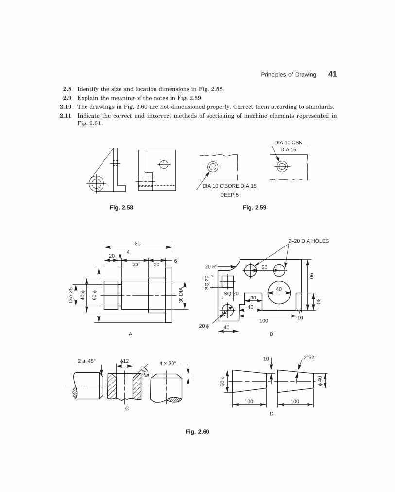
Principles of Drawing 41
dharmd:\N-Design\Des2-1.pm5 Seventh Print
2.8 Identify the size and location dimensions in Fig. 2.58.
2.9 Explain the meaning of the notes in Fig. 2.59.
2.10 The drawings in Fig. 2.60 are not dimensioned properly. Correct them according to standards.
2.11 Indicate the correct and incorrect methods of sectioning of machine elements represented inFig. 2.61.
DIA 10 C’BORE DIA 15
DEEP 5
DIA 10 CSKDIA 15
Fig. 2.58 Fig. 2.59
80
30 20
204
30D
IA
60f
40f
DIA
25
A
20 R
SQ
20
SQ 20
20 f 40100
40
30
40
10
3090
50
2–20 DIA HOLES
B
100
60f
10
100
2°52¢
f40
D
6
2 at 45° f12 4 × 30°
45°
C
Fig. 2.60

42 Machine Drawing
dharmd:\N-Design\Des2-1.pm5 Seventh Print
(a)
X
X (b)
X
X(c)
(d)
Fig. 2.61

43
3�����������
��������
��� �����������
Any object has three dimensions, viz., length, width and thickness. A projection is defined as arepresentation of an object on a two dimensional plane. The projections of an object shouldconvey all the three dimensions, along with other details of the object on a sheet of paper. Theelements to be considered while obtaining a projection are :
(i) The object(ii) The plane of projection
(iii) The point of sight(iv) The rays of sightA projection may be obtained by viewing the object from the point of sight and tracing in
correct sequence, the points of intersection between the rays of sight and the plane on to whichthe object is projected. A projection is called orthographic projection when the point of sight isimagined to be located at infinity so that the rays of sight are parallel to each other and intersectthe plane of projection at right angle to it.
The principles of orthographic projection may be followed in four different angles orsystems, viz., first, second, third and fourth angle projections. A projection is said to be first,second, third or fourth angle when the object is imagined to be in the first, second, third orfourth quadrant respectively. However, the Bureau of Indian Standards (SP–46:1988) prefersfirst angle projection and throughout this book, first angle projection is followed.
��� ��������� ��� ��� �� ������ ��������
In first angle projection, the object is imagined to be positioned in the first quadrant. The viewfrom the front of the object is obtained by looking at the object from the right side of thequadrant and tracing in correct sequence, the points of intersection between the projectionplane and the rays of sight extended. The object is between the observer and the plane ofprojection (vertical plane). Here, the object is imagined to be transparent and the projectionlines are extended from various points of the object to intersect the projection plane. Hence,in first angle projection, any view is so placed that it represents the side of the object awayfrom it.

44 Machine Drawing
dharmd:\N-Design\Des3-1.pm5 Seventh Print
View fromthe left
View fromthe left
Profileplane
Vertical plane
��� ������ � ��� ���������� ������������ ����
����� �������� �!"�����#!
The view from the front of an object is defined as the view that is obtained as projection on thevertical plane by looking at the object normal to its front surface. It is the usual practice toposition the object such that its view from the front reveals most of the important features.Figure 3.1 shows the method of obtaining the view from the front of an object.
Vertical
plane
View from
the frontView from
the front
Horizontal plane
View from
above
Vertical plane
Horizontal plane
Fig. 3.1 Principle of obtaining the Fig. 3.2 Principle of obtaining the view from the front view from above
����� �������� ��$�%�
The view from above of an object is defined as theview that is obtained as projection on the horizontalplane, by looking the object normal to its topsurface. Figure 3.2 shows the method of obtainingthe view from above of an object.
����� �������� �!"�� �&�
The view from the side of an object is defined asthe view that is obtained as projection on theprofile plane by looking the object, normal to itsside surface. As there are two sides for an object,viz., left side and right side, two possible views fromthe side, viz., view from the left and view from theright may be obtained for any object. Figure 3.3shows the method of obtaining the view from theleft of an object.
Fig. 3.3 Principle of obtaining theview from the left
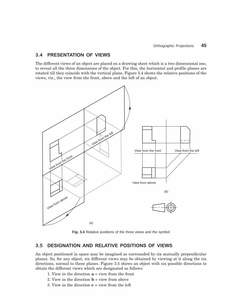
Orthographic Projections 45
dharmd:\N-Design\Des3-1.pm5 Seventh Print
��' ��� ��������� ��� ����
The different views of an object are placed on a drawing sheet which is a two dimensional one,to reveal all the three dimensions of the object. For this, the horizontal and profile planes arerotated till they coincide with the vertical plane. Figure 3.4 shows the relative positions of theviews, viz., the view from the front, above and the left of an object.
View from the left
View from the left
View from the fro
nt
View from the fro
nt
View from above
View from above
(a)
View from the frontView from the front View from the leftView from the left
View from aboveView from above
(b)
Fig. 3.4 Relative positions of the three views and the symbol
��( �� ��������� ���� ��������� �� ����� � ��� ����
An object positioned in space may be imagined as surrounded by six mutually perpendicularplanes. So, for any object, six different views may be obtained by viewing at it along the sixdirections, normal to these planes. Figure 3.5 shows an object with six possible directions toobtain the different views which are designated as follows:
1. View in the direction a = view from the front2. View in the direction b = view from above3. View in the direction c = view from the left
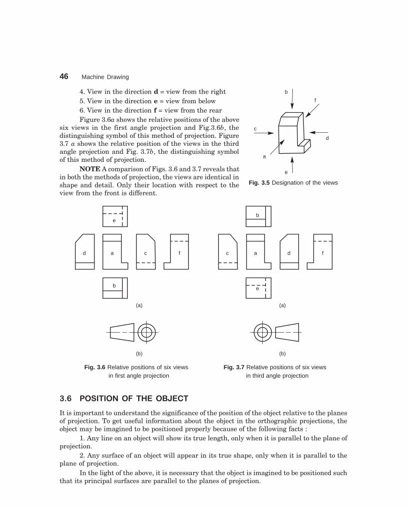
46 Machine Drawing
dharmd:\N-Design\Des3-1.pm5 Seventh Print
b
f
d
a
c
e
4. View in the direction d = view from the right5. View in the direction e = view from below6. View in the direction f = view from the rearFigure 3.6a shows the relative positions of the above
six views in the first angle projection and Fig.3.6b, thedistinguishing symbol of this method of projection. Figure3.7 a shows the relative position of the views in the thirdangle projection and Fig. 3.7b, the distinguishing symbolof this method of projection.
NOTE A comparison of Figs. 3.6 and 3.7 reveals thatin both the methods of projection, the views are identical inshape and detail. Only their location with respect to theview from the front is different.
e
d a c f
b
(a)
(b)
b
c a d f
e
(a)
(b)
Fig. 3.6 Relative positions of six views Fig. 3.7 Relative positions of six views in first angle projection in third angle projection
��) �� ��������� ��������
It is important to understand the significance of the position of the object relative to the planesof projection. To get useful information about the object in the orthographic projections, theobject may be imagined to be positioned properly because of the following facts :
1. Any line on an object will show its true length, only when it is parallel to the plane ofprojection.
2. Any surface of an object will appear in its true shape, only when it is parallel to theplane of projection.
In the light of the above, it is necessary that the object is imagined to be positioned suchthat its principal surfaces are parallel to the planes of projection.
Fig. 3.5 Designation of the views
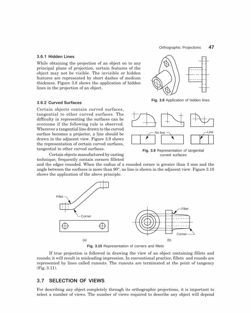
Orthographic Projections 47
dharmd:\N-Design\Des3-1.pm5 Seventh Print
LineNo line
Fig. 3.9 Representation of tangentialcurved surfaces
��)�� ��&&�#���#�*
While obtaining the projection of an object on to anyprincipal plane of projection, certain features of theobject may not be visible. The invisible or hiddenfeatures are represented by short dashes of mediumthickness. Figure 3.8 shows the application of hiddenlines in the projection of an object.
��)�� +�%�&� +�,-.�*
Certain objects contain curved surfaces,tangential to other curved surfaces. Thedifficulty in representing the surfaces can beovercome if the following rule is observed.Wherever a tangential line drawn to the curvedsurface becomes a projector, a line should bedrawn in the adjacent view. Figure 3.9 showsthe representation of certain curved surfaces,tangential to other curved surfaces.
Certain objects manufactured by castingtechnique, frequently contain corners filletedand the edges rounded. When the radius of a rounded corner is greater than 3 mm and theangle between the surfaces is more than 90°, no line is shown in the adjacent view. Figure 3.10shows the application of the above principle.
(a)
Fillet
Corner
(b)
Fillet
Corner
Fig. 3.10 Representation of corners and fillets
If true projection is followed in drawing the view of an object containing fillets androunds; it will result in misleading impression. In conventional practice, fillets and rounds arerepresented by lines called runouts. The runouts are terminated at the point of tangency(Fig. 3.11).
��/ �������� ��� ����
For describing any object completely through its orthographic projections, it is important toselect a number of views. The number of views required to describe any object will depend
Fig. 3.8 Application of hidden lines

48 Machine Drawing
dharmd:\N-Design\Des3-1.pm5 Seventh Print
Tangentpoint Fillet
Runout
upon the extent of complexity involved in it. The higher thesymmetry, the lesser the number of views required.
��/�� �#�0�������-��#1*
Some objects with cylindrical, square or hexagonal featuresor, plates of any size with any number of features in it maybe represented by a single view. In such cases, the diameterof the cylinder, the side of the square, the side of the hexagonor the thickness of the plate may be expressed by a note orabbreviation. Square sections are indicated by light crosseddiagonal lines. Figure 3.12 shows some objects which maybe described by one-view drawings.
f50
f50
f32
f32
�65
38
584616
180
(a)
M 202 HOLES,
DIA 20
3 THICK
R 12R 18
35
100
(b)
R30
Fig. 3.12 One view drawings
��/�� ���0�������-��#1*
Some objects which are symmetricalabout two axes may be representedcompletely by two views Normally, thelargest face showing most of the detailsof the object is selected for drawing theview from the front. The shape of theobject then determines whether thesecond view can be a view from aboveor a side view. Figure 3.13 shows theexample of two-view drawings.
Fig. 3.11 Runouts
Fig. 3.13 Two view drawing
R 35f 35
20
8
405
f 15
180
140
3333
R 8

Orthographic Projections 49
dharmd:\N-Design\Des3-1.pm5 Seventh Print
��/�� �"���0�������-��#1*
In general, most of the objects consisting of either a single component or an assembly of anumber of components, are described with the help of three views. In such cases, the viewsnormally selected are the views from the front, above and left or right side. Figure 3.14 showsan object and its three necessary views.
(b)
2020
3535
25
10
1060
1035
45
(a)
70
10
15
1515
Fig. 3.14 Three view drawing

50 Machine Drawing
dharmd:\N-Design\Des3-1.pm5 Seventh Print
��2 ������������ ��� �� ���� ����
When two views of an object are given, the third view may be developed by the use of a mitreline.
��2�� ���.�#*!�+.!�!"��%����,�� �!"��3�,!4�,�� �!"��!���1�%�#�%���*
Construction (Fig. 3.15)1. Draw the views from the front and above.2. Draw the projection lines to the right of the view from above.3. Decide the distance, D from the view from the front at which, the side view is to be
drawn.4. Construct a mitre line at 45°.5. From the points of intersection between the mitre line and the projection lines, draw
vertical projection lines.6. Draw the horizontal projection lines from the view from the front to intersect the
above lines. The figure obtained by joining the points of intersection in the order is the requiredview.
Figure 3.16 shows the steps to be followed in constructing the view from above of anobject, from the given views from the front and left.
NOTE These exercises are aimed at improving the practice in reading and developingthe imagination of the student.
D
Mitreline
45°
(a)
(b)
D
45°
Mitreline
(a)
(b)
Fig. 3.15 Construction of the view from the left Fig. 3.16 Construction of the view from above
��5 ������ ���� ����
The views of a given object must be positioned on the drawing sheet so as to give a good andbalanced appearance. Keeping in view, (i) number of views, (ii) scale and (iii) space between
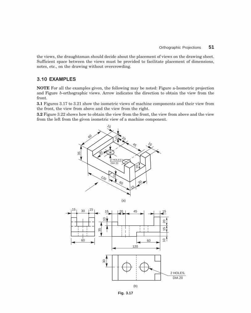
Orthographic Projections 51
dharmd:\N-Design\Des3-1.pm5 Seventh Print
the views, the draughtsman should decide about the placement of views on the drawing sheet.Sufficient space between the views must be provided to facilitate placement of dimensions,notes, etc., on the drawing without overcrowding.
���6 �7�����
NOTE For all the examples given, the following may be noted: Figure a-Isometric projectionand Figure b-orthographic views. Arrow indicates the direction to obtain the view from thefront.3.1 Figures 3.17 to 3.21 show the isometric views of machine components and their view fromthe front, the view from above and the view from the right.3.2 Figure 3.22 shows how to obtain the view from the front, the view from above and the viewfrom the left from the given isometric view of a machine component.
12060 30
15
10
20
30
2 HOLES,DIA 20
15
20
45
15
1060
35
15 1530
(a)
60
35
15 20 45 15
10
2015
120
60 10
30
2 HOLES,
DIA 20
(b)
Fig. 3.17

52 Machine Drawing
dharmd:\N-Design\Des3-1.pm5 Seventh Print
12
1516
1640
75
70
100
6430
60°
2212
(a)
16 1632
1612
75
60°
30
15 70
40
100
22
64
12
(b)
Fig. 3.18
12
12
16
60
12
12
f16
40
f16 20 20
R20f16
(a)
12 1216
40
60
R4 HOLES,DIA 16
1220
12
40
R
(b)
Fig. 3.19
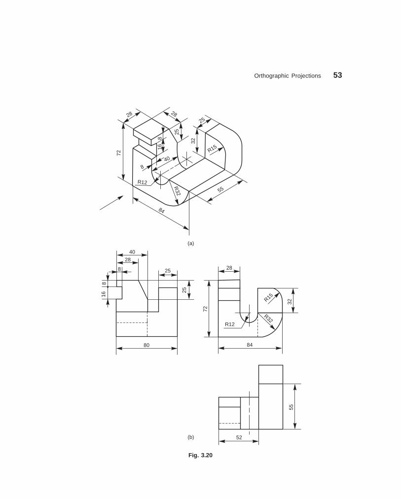
Orthographic Projections 53
dharmd:\N-Design\Des3-1.pm5 Seventh Print
28 28
25
816
840
R12
7225
32
R15
55
R32
84
(a)
80
25
40
28
8
816
25
72
28
R1532
R32R12
84
52
55
(b)
Fig. 3.20

54 Machine Drawing
dharmd:\N-Design\Des3-1.pm5 Seventh Print
Fig. 3.21
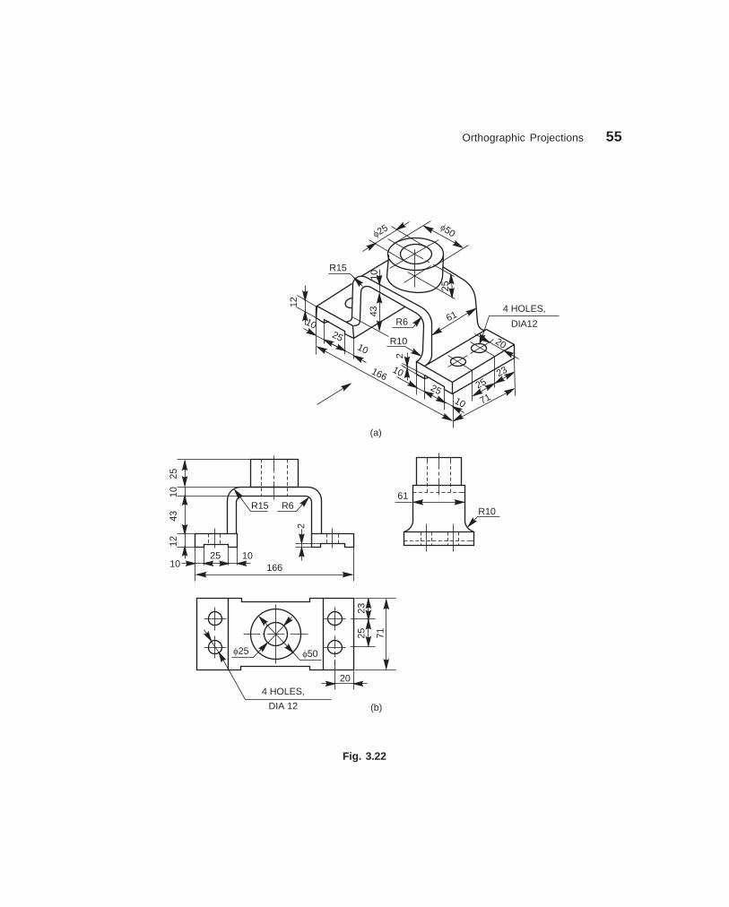
Orthographic Projections 55
dharmd:\N-Design\Des3-1.pm5 Seventh Print
f25 f50
R15
10
25
43
R6
R10
61
12
1025
10
16610
2510
271
2523
20
4 HOLES,
DIA12
(a)
2510
4312
101025
2
166
R15 R661
R10
f25 f50
204 HOLES,
DIA 12 (b)
2523
71
Fig. 3.22

56 Machine Drawing
dharmd:\N-Design\Des3-1.pm5 Seventh Print
THEORY QUESTIONS
3.1 What are the elements to be considered while obtaining a projection and what is an orthographicprojection ?
3.2 When is a projection of an object called an orthographic projection?
3.3 Explain the following, indicating the symbol to be used in each case:
(a) First angle projection, (b) Third angle projection
3.4 List-out the six possible orthographic projections that may be obtained for an object in space,specifying their relative positions.
3.5 What is a one-view drawing ? For what type of objects these can be used ?
3.6 What is the basis on which the number of views required for an object is selected ?
3.7 What are the points to be considered while laying-out the different views of an object ?
DRAWING EXERCISES
3.1 Draw (i) the view from the front and (ii) the view from right of the object shown in Fig. 3.23.
3.2 Draw (i) the view from the front, (ii) the view from above and (iii) the view from the right, of theobjects shown in Figs. 3.24, 3.27, 3.28, 3.31 and 3.38.
3.3 Draw (i) the view from the front and (ii) the view from above of the objects shown in Figs. 3.25,3.32, 3.34, 3.36 and 3.37.
3.4 Draw (i) the view from the front, (ii) the view from above and (iii) the view from the left of theobjects shown in Figs. 3.26, 3.29, 3.30, 3.33 and 3.35.
20
10
40
20
20
10
303020
60
30
20
20
20
25100
25
40
40
20
25
30
3065
12
12
1075
Fig. 3.23 Fig. 3.24

Orthographic Projections 57
dharmd:\N-Design\Des3-1.pm5 Seventh Print
3010
R 30
f 25
f 40R 50
2 HOLES, DIA 1020
80
50
10
R 20
80
R 1565
12
24
24
5612
9
32
369
25
50
16
75
Fig. 3.25 Fig. 3.26
35
453515
50
30
80 25
10065
20
20
2010
4030
407025
30
50100
40
20
15
Fig. 3.27 Fig. 3.28
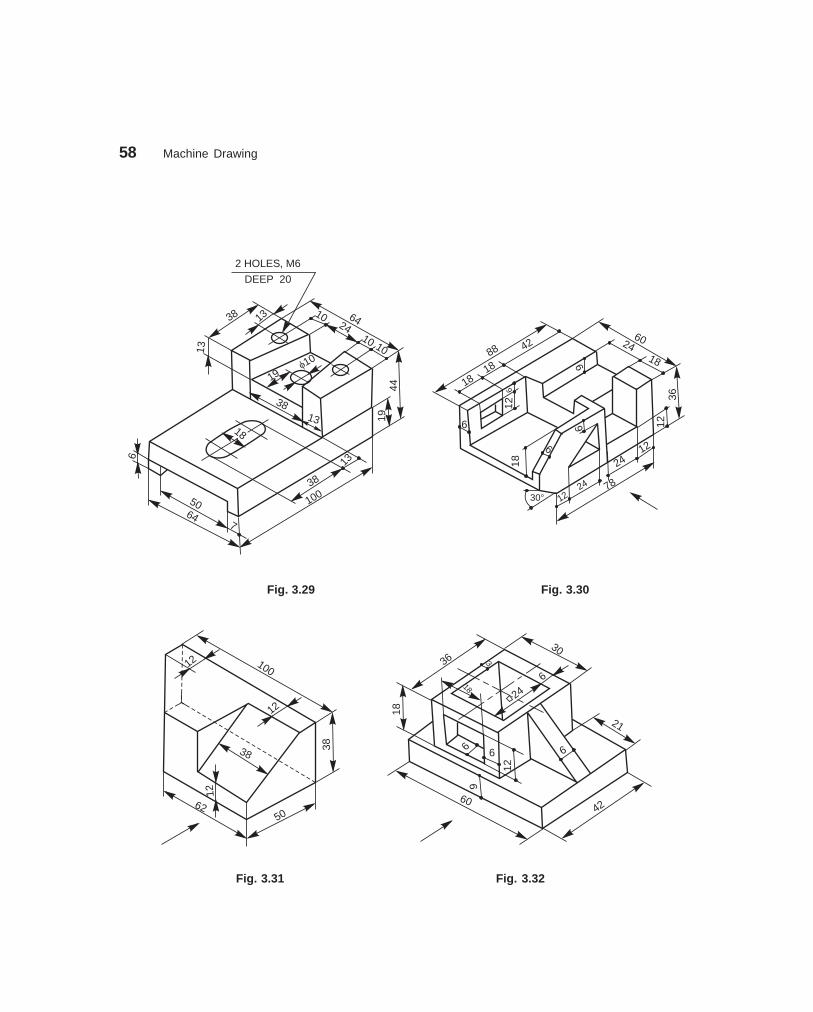
58 Machine Drawing
dharmd:\N-Design\Des3-1.pm5 Seventh Print
19f10
1338
13
1944
6424
38
2 HOLES, M6
DEEP 20
38
5064
7
100
6
10
1010
13
131818
88 42
18
18
9
6
6
2418
60
36126
6
18
30° 1224
2412
78
12
Fig. 3.29 Fig. 3.30
10012
12
12
38
38
6250
3630
3
6
2424
18
6
21
6
12
6
18
60
9
42
Fig. 3.31 Fig. 3.32

Orthographic Projections 59
dharmd:\N-Design\Des3-1.pm5 Seventh Print
25
16
15
19
22
22
12
50
25
7525
12
63
12
1212
2015
30
20
12
30
R 10
62
1520
15
30°
1515
2 HOLES,DIA 15
12125
6212
12
2 HOLES,DIA 12
Fig. 3.33 Fig. 3.34
36
R 30
9045
3024
35
7250 10 70
145
R 12
2424
25
50
f 24
5 5
36f
30f
55
R25
12
24
12
12
f 18
100
70
35
3050
38
18
140
85
18
18
3
2 HOLES,DIA 16
f 40
20
Fig. 3.35 Fig. 3.36

60 Machine Drawing
dharmd:\N-Design\Des3-1.pm5 Seventh Print
3738
1212
1231
50 75
20025
17562 25
38
50
100 5012
5050
75
�25
12
80
5
R13
R13
20
6
R2311
10R16
15
2224
38
10
2242
f1546248
� 9
OIL HOLE,DIA 3
36f
18f28
54
102 HOLES,
DIA 12
18
10
20
82
10
1846 6
154 54
R18
R 28
10
R 3
R 10
10
20
72
45
10
24
f10
1060°
30°
2444
1045°
5
96
6036
24
18
12
1030
60
1212 10
60°
Fig. 3.37 Fig. 3.38
3.5 Draw (i) the view from the front, (ii) the view fromthe right and (iii) the view from the left of the ob-ject shown in Fig. 3.39.
3.6 Draw (i) the view from the front and(ii) the view from the left of the ob-jects shown in Figs. 3.40, 3.41, 3.42and 3.43.
Fig. 3.39
Fig. 3.40

Orthographic Projections 61
dharmd:\N-Design\Des3-1.pm5 Seventh Print
22 40
100
10
36
2012
35
70
DIA 12,DEEP 16
R 25
R 16
20
26
12
26
46
f50
f25
1412
12
18
36
12
30
15
1518
f 36
f 15
85
3
501814
12
22
4011
0
18
18
34
f 32
f 50
Fig. 3.41 Fig. 3.42
12
R 18
60 12
36
R 18
R8 922
12
25
12
90
60
1212
25
25
f18
Fig. 3.43
3.7 Isometric views of a few objects are given on the left hand side of Fig. 3.44. The orthographicviews are shown on the right side. Name the views.
3.8 Two views of each object are given in Fig. 3.45. Sketch the missing views of the same.
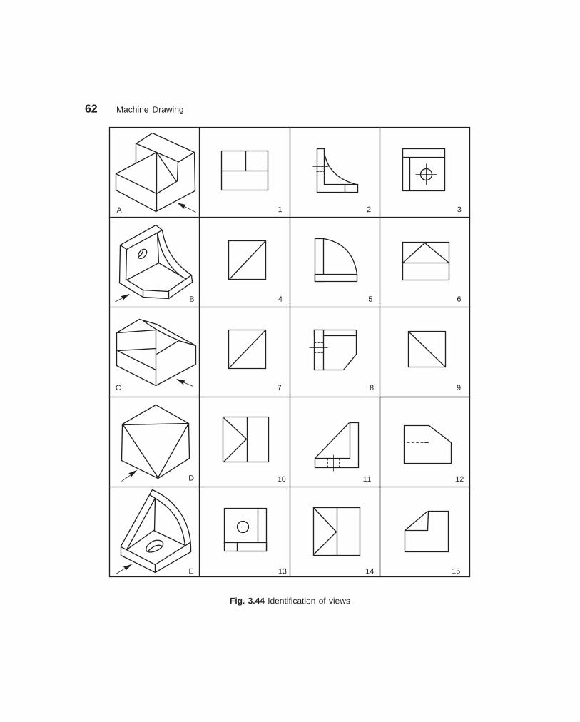
62 Machine Drawing
dharmd:\N-Design\Des3-1.pm5 Seventh Print
A 1 2 3
B 4 5 6
C 7 8 9
10 11 12
E 13 14 15
D
Fig. 3.44 Identification of views
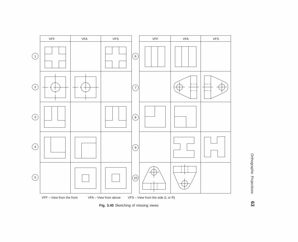
Orthographic P
rojections63
dharmd:\N
-Design\D
es3-1.pm5
Seven
th P
rint
Fig. 3.45 Sketching of missing views
VFSVFAVFFVFSVFAVFF
6
7
8
9
10
1
2
3
4
5
VFF – View from the front VFA – View from above VFS – View from the side (L or R)

��� ����������
Orthographic views when carefully selected, may reveal the external features of even the mostcomplicated objects. However, there are objects with complicated interior details and whenrepresented by hidden lines, may not effectively reveal the true interior details. This may beovercome by representing one or more of the views ‘in section’.
A sectional view is obtained by imagining the object, as if cut by a cutting plane and theportion between the observer and the section plane being removed. Figure 4.1a shows an object,with the cutting plane passing through it and Fig. 4.1b, the two halves drawn apart, exposing theinterior details.
(b)(a)
Cutting plane
Fig. 4.1 Principles of sectioning
��� ����� ��� �
A sectional view obtained by assuming that the object is completely cut by a plane is called a fullsection or sectional view. Figure 4.2a shows the view from the right of the object shown in Fig. 4.1a,in full section. The sectioned view provides all the inner details, better than the unsectioned viewwith dotted lines for inner details (Fig. 4.2b). The cutting plane is represented by its trace (V.T) inthe view from the front (Fig. 4.2c) and the direction of sight to obtain the sectional view is representedby the arrows.
4� ���������� ��
64
dharmd:\N-Design\Des4-1.pm5

Sectional Views 65
dharmd:\N-Design\Des4-1.pm5 Seventh Print
X
X
X – X
(a) (b) (c)
Fig. 4.2 Sectioned and un-sectioned views
It may be noted that, in order to obtain a sectional view, only one half of the object isimagined to be removed, but is not actually shown removed anywhere except in the sectionalview. Further, in a sectional view, the portions of the object that have been cut by the plane arerepresented by section lining or hatching. The view should also contain the visible parts behindthe cutting plane.
Figure 4.3 represents the correct and incorrect ways of representing a sectional view.Sections are used primarily to replace hidden line representation, hence, as a rule, hidden linesare omitted in the sectional views.
X
X
X – X
Incorrect Correct
Fig. 4.3 Incorrect and correct sections
��� ����� � �����
A half sectional view is preferred for symmetrical objects. For a half section, the cutting planeremoves only one quarter of an object. For a symmetrical object, a half sectional view is used toindicate both interior and exterior details in the same view. Even in half sectional views, it is agood practice to omit the hidden lines. Figure 4.4a shows an object with the cutting plane inposition for obtaining a half sectional view from the front, the top half being in section. Figure4.4b shows two parts drawn apart, exposing the inner details in the sectioned portion. Figure 4.4c

66 Machine Drawing
dharmd:\N-Design\Des4-1.pm5 Seventh Print
XX
X – X
Auxiliary view
shows the half sectional view from the front. It may be noted that a centre line is used to separatethe halves of the half section. Students are also advised to note the representation of the cuttingplane in the view from above, for obtaining the half sectional view from the front.
(a) (b)
(c)
Fig. 4.4 Method of obtaining half sectional view
��� ���������� ��� ��
Auxiliary sections may be used to supplement theprincipal views used in orthographic projections. Asectional view projected on an auxiliary plane,inclined to the principal planes of projection, showsthe cross-sectional shapes of features such as arms,ribs and so on. In Fig. 4.5, auxiliary cutting planeX-X is used to obtain the auxiliary section X-X.
Fig. 4.5 Auxiliary section

Sectional Views 67
dharmd:\N-Design\Des4-1.pm5 Seventh Print
��� ������
4.1 Figure 4.6 shows the isometric view of a machine block and (i) the sectional view from thefront, (ii) the view from above and (iii) the sectional view from the left.
15
8
810
20
10
515
10
20
8
24
28
25
8
10
3580 35
30
100
308 8
8
827
15
25
20
40
100
(a)
24
10
88
15
25
80
(b)
Fig. 4.6 Machine block

68 Machine Drawing
dharmd:\N-Design\Des4-1.pm5 Seventh Print
4.2 Figure 4.7 shows the isometric view of a shaft support. Sectional view from the front, theview from above and the view from the right are also shown in the figure.
f 50DIA 20 C BORE DIA 30
DEEP 6
¢
28 12
f 6
R 15
10
35
35
2 HOLES,
DIA 12 (a)
2810
f 50f 30
6
12
f6
f12
70 15
f20
f20
2 HOLES,DIA12
R 15
(b)
Fig. 4.7 Shaft support
4.3 Figure 4.8 shows the isometric view of a machine component along with the sectional viewfrom the front, the view from above and the view from the left.
4.4 Figure 4.9 shows a sliding block and (i) the view from the front, (ii) the view from aboveand (iii) the sectional view from the right.

Sectional Views 69
dharmd:\N-Design\Des4-1.pm5 Seventh Print
(a)
40R24
32
8
8 f 32 56
90
f 56
640
90
24
56
R
328
8
f56
6
f 32
(b)
Fig. 4.8 Machine component
DIA 20 C BORE
DIA 50 DEEP 10
¢
8545
20
10
4290
25
180
45
70
25f 30
R 30
20
5515
15
10
f50
42f 20
90
180
45
1515 553520
80
f 30
R 30
8545 20
2510
70
(a) (b)
Fig. 4.9 Sliding block
4.5 Figure 4.10 shows the orthographic views of a yoke. The figure also shows the sectionalview from the front, the sectional view from the right and the view from above.
4.6 Figure 4.11 shows the orthographic views of a bearing bracket. The sectional view fromthe right and view from above are developed and shown in the figure.

70 Machine Drawing
dharmd:\N-Design\Des4-1.pm5 Seventh Print
252575
25
R10
View from the right
f 55f 35 R10
20
7010
20 60160
View from the front(a)
Sectional viewfrom the right
Sectional view from the front
View from above
(b)
Fig. 4.10 Yoke
f45
DIA3 CSK DIA 5
24 10 24
55 21
20
f 20
15
R 10 R 10
75
115
145
f 1475
(a)
Fig. 4.11 Bearing bracket (Contd.)
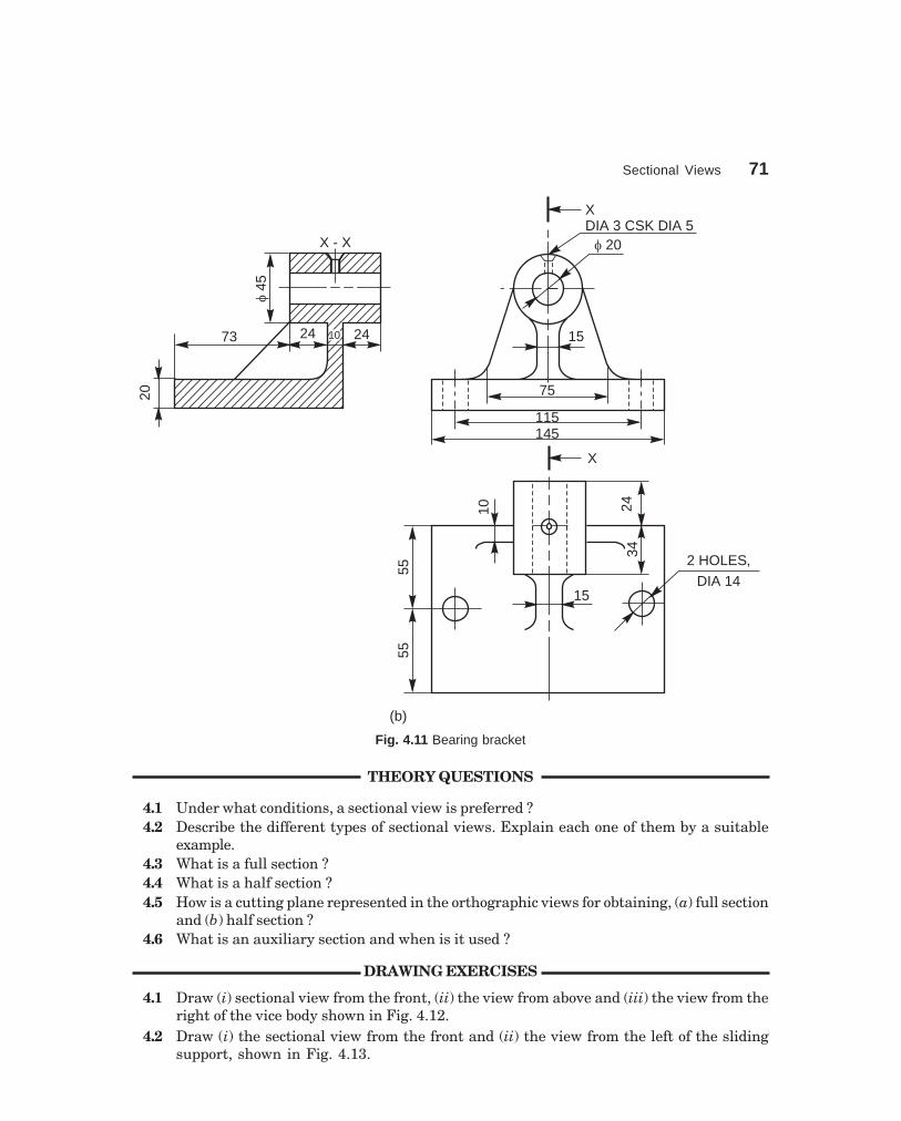
Sectional Views 71
dharmd:\N-Design\Des4-1.pm5 Seventh Print
X - Xf
45
24 2473
20
XDIA 3 CSK DIA 5
f 20
15
75
115145
X
15
342410
5555
2 HOLES,
DIA 14
(b)
10
Fig. 4.11 Bearing bracket
THEORY QUESTIONS
4.1 Under what conditions, a sectional view is preferred ?4.2 Describe the different types of sectional views. Explain each one of them by a suitable
example.4.3 What is a full section ?4.4 What is a half section ?4.5 How is a cutting plane represented in the orthographic views for obtaining, (a) full section
and (b) half section ?4.6 What is an auxiliary section and when is it used ?
DRAWING EXERCISES
4.1 Draw (i) sectional view from the front, (ii) the view from above and (iii) the view from theright of the vice body shown in Fig. 4.12.
4.2 Draw (i) the sectional view from the front and (ii) the view from the left of the slidingsupport, shown in Fig. 4.13.

72 Machine Drawing
dharmd:\N-Design\Des4-1.pm5 Seventh Print
M 15R 15
2530
55
22
22
35
80
R 28
70
50 2020
20
20
70
32 1805
2 HOLES,
DIA 8
48
48
38
f30R 22
15
3244
6420
34 7
10
f20
6
3854
Fig. 4.12 Vice body Fig. 4.13 Sliding support
4.3 Draw (i) the sectional view from the front, (ii) the view from above and (iii) the view fromright of the shaft bracket shown in Fig. 4.14.
4.4 Draw (i) the sectional view from the front, (ii) the view from above and (iii) the view fromthe left and (iv) the view from the right of an anchor bracket shown in Fig. 4.15.
6
f 25
f 10
3
6
R 6
R 12
6
30
2
R 3
1530
50R20
R 30R
15
65
25
15
1060
75
Fig. 4.14 Shaft bracket Fig. 4.15 Anchor bracket
4.5 Draw (i) the sectional view from the front, (ii) the view from above and (iii) the view fromthe left of a fork shown in Fig. 4.16.
4.6 Draw (i) the view from the front, (ii) sectional view from above and (iii) the view from theright of a depth stop shown in Fig. 4.17.
4.7 Draw (i) the view from the front, (ii) the view from above and (iii) the sectional view fromthe left of a centering bearing shown in Fig. 4.18.
4.8 Draw (i) the view from the front and (ii) the sectional view from above of a flange connectorshown in Fig. 4.19.
4.9 Draw (i) the sectional view from the front and (ii) the view from above of a bearing bracketshown in Fig. 4.20.

Sectional Views 73
dharmd:\N-Design\Des4-1.pm5 Seventh Print
f 80
20
20
80
15
20 80
f 30
55
f 30
� 60
15
7
6
10
20
f 26f 14
6
7
3
55
30
f 32f 48
f5
Fig. 4.16 Fork Fig. 4.17 Depth stop
f 100
f 40f 32
155 40
4 HOLES, DIA 6
EQUI-SP
4 HOLES, DIA 10
EQUI-SP ON
80 PCD
3 × 45°
10
R 25
R 20
f 60
2515
5
10
9030
3
4 HOLES, DIA 10ON 80 PCD
80
40R 21
f 30
45°
R 55
R 95
5
45
10
2 HOLES,
DIA 14
R 12
Fig. 4.18 Centering bearing Fig. 4.19 Flange connector
4.10 Draw (i) the sectional view from the front and (ii) the view from the left of a shaft supportshown in Fig. 4.21.
4.11 Draw (i) the sectional view from the front, (ii) the view from above and (iii) the view fromthe left of a motor bracket shown in Fig. 4.22.
4.12 Draw (i) the sectional view from the front, (ii) the view from above and (iii) the view fromthe left of a machine block shown in Fig. 3.35.
4.13 Draw (i) the sectional view from the front, (ii) the view from above and (iii) the view fromthe right of a shaft support shown in Fig. 3.37.
4.14 Draw (i) the sectional view from the front, (ii) the view from above and (iii) the view fromthe left of a sliding block shown in Fig. 3.40.
4.15 Draw (i) the sectional view from the front, (ii) the view from above and (iii) the view fromthe left of a vice body shown in Fig. 3.41.
4.16 Develop the sectional view from left, from the orthographic views of a sliding bracket givenin Fig. 4.23.

74 Machine Drawing
dharmd:\N-Design\Des4-1.pm5 Seventh Print
120
30
9070
18
20f15f15
612
R42
R18
24 12
655
f 40f 80
125
R 12
14
35
15
4 HOLES,DIA 10
10
5080
6090
120
30
5
10
WEB 10
60
60 f 70
f 50
Fig. 4.20 Bearing bracket Fig. 4.21 Shaft support
12
M 5
55
3
R8f6
517.5
17.5 17
25
DIA 6,
DEEP 12
30
3
3Through slot25
33
33
R12
21
f25
f16
20
f 40f 06
60
6
40408
8
2014
90
406010
20
Fig. 4.22 Motor bracket Fig. 4.23 Sliding bracket
4.17 Develop the sectional view from left, from the orthographic views of a shaft bearinggiven in Fig. 4.24.
4.18 Develop the sectional view from the front of the shifter, from the orthographic viewsshown in Fig. 4.25.
4.19 Develop (i) the sectional view from above and (ii) the view from the left of shaftbracket, from the orthographic views shown in Fig. 4.26.
4.20 Develop the sectional view from the left of a hanger, from the orthographic viewsshown in Fig. 4.27.

Sectional Views 75
dharmd:\N-Design\Des4-1.pm5 Seventh Print
30 30
50
100
2 HOLES,DIA 15
12
110
30
75
30
f20
f30
f60
12
10 3512
1236
75
22
4222
6
M 6
46
22
202.
5
f 7.5
f 24f 48
12
18 85 30
Fig. 4.24 Shaft bearing Fig. 4.25 Shifter
R 5045°
20
SLOT, 14
f 30 R 25
30
7512
75 50
1502 HOLES, DIA 20
CSK DIA 40
7010
090
3045
210
12
2472
10727212
10
f 36 f 60
R 60
4 HOLES, DIA 10
123660
20 20
Fig. 4.26 Shaft bracket Fig. 4.27 Hanger

76 Machine Drawing
dharmd:\N-Design\Des4-1.pm5 Seventh Print
4.21 Develop (i) the view from above and (ii) the sectional view from the left of a lever,from the orthographic views shown in Fig. 4.28.
f4030
253
6
12
f40
32
2020
f 18
100 10
25
30°
f 18
32 M 8
65
16
16 25
DIA3 CSK DIA 5
Fig. 4.28 Lever

��� ����������
A machine element used for holding or joining two or more parts of a machine or structure isknown as a fastener. The process of joining the parts is called fastening. The fasteners are of twotypes : permanent and removable (temporary). Riveting and welding processes are used for fasteningpermanently. Screwed fasteners such as bolts, studs and nuts in combination, machine screws,set screws, etc., and keys, cotters, couplings, etc., are used for fastening components that requirefrequent assembly and dissembly.
Screwed fasteners occupy the most prominent place among the removable fasteners. Ingeneral, screwed fasteners are used : (i) to hold parts together, (ii) to adjust parts with referenceto each other and (iii) to transmit power.
��� ����� ������ �����������
A screw thread is obtained by cutting a continuous helical groove on a cylindrical surface(external thread). The threaded portion engages with a corresponding threaded hole (internalthread); forming a screwed fastener. Following are the terms that are associated with screwthreads (Fig. 5.1).
Angle of thread
P
Min
ordi
a.P
itch
dia.
Maj
ordi
a.
CrestCrestRootRoot
FlankFlank
Fig. 5.1 Screw thread nomenclature
1. Major (nominal) diameterThis is the largest diameter of a screw thread, touching the crests on an external thread or theroots of an internal thread.2. Minor (core) diameterThis is the smallest diameter of a screw thread, touching the roots or core of an external thread(root or core diameter) or the crests of an internal thread.
5���������������
77
dharmd:\N-Design\Des5-1.pm5

78 Machine Drawing
dharmd:\N-Design\Des5-1.pm5 Seventh Print
3. Pitch diameterThis is the diameter of an imaginary cylinder, passing through the threads at the points wherethe thread width is equal to the space between the threads.4. PitchIt is the distance measured parallel to the axis, between corresponding points on adjacent screwthreads.5. LeadIt is the distance a screw advances axially in one turn.6. FlankFlank is the straight portion of the surface, on either side of the screw thread.7. CrestIt is the peak edge of a screw thread, that connects the adjacent flanks at the top.8. RootIt is the bottom edge of the thread that connects the adjacent flanks at the bottom.9. Thread angleThis is the angle included between the flanks of the thread, measured in an axial plane.
��� ���� � ��� �����
Bureau of Indian Standards (BIS) adapts ISO (International Organisation for Standards) metricthreads which are adapted by a number of countries apart from India.
The design profiles of external and internal threads are shown in Fig. 5.2. The followingare the relations between the various parameters marked in the figure :
0.125P
The root is rounded and cleared
beyond a width of 0.125P
DD
2
D1
H1
0.25
H
Internalthreads 60°
P
R
0.5 P
0.25 H
d3 d2 d
h3
0.5
H0.
5H
H
0.12
5H
Internal thread diametersD - Major diameter
D - Pitch diameterD - Minor diameter
2
1
External thread diametersd - Major diameter
- Pitch diameter- Minor diameter
2dd3
0.16
7H
Externalthreads
60°
Fig. 5.2 Metric screw thread
P = Pitch d3 = d2 – 2 (H/2 – H/6)H = 0.86 P = d – 1.22PD = d = Major diameter H1 = (D – D1)/2 = 5H/8 = 0.54P
D2 = d2 = d – 0.75H h3 = (d – d3)/2 = 17/24H = 0.61P D1 = d2 – 2(H/2 – H/4) = d – 2H1 R = H/6 = 0.14P
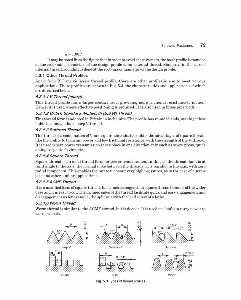
Screwed Fasteners 79
dharmd:\N-Design\Des5-1.pm5 Seventh Print
= d – 1.08PIt may be noted from the figure that in order to avoid sharp corners, the basic profile is rounded
at the root (minor diameter) of the design profile of an external thread. Similarly, in the case ofinternal thread, rounding is done at the root (major diameter) of the design profile.
����� ����������������� !�"
Apart from ISO metric screw thread profile, there are other profiles in use to meet variousapplications. These profiles are shown in Fig. 5.3, the characteristics and applications of whichare discussed below :
������������� ������
This thread profile has a larger contact area, providing more frictional resistance to motion.Hence, it is used where effective positioning is required. It is also used in brass pipe work.
������������������ � �������������������
This thread form is adopted in Britain in inch units. The profile has rounded ends, making it lessliable to damage than sharp V-thread.
���������������� ��
This thread is a combination of V-and square threads. It exhibits the advantages of square thread,like the ability to transmit power and low frictional resistance, with the strength of the V-thread.It is used where power transmission takes place in one direction only such as screw press, quickacting carpenter’s vice, etc.
�������������� ��
Square thread is an ideal thread form for power transmission. In this, as the thread flank is atright angle to the axis, the normal force between the threads, acts parallel to the axis, with zeroradial component. This enables the nut to transmit very high pressures, as in the case of a screwjack and other similar applications.
����������������
It is a modified form of square thread. It is much stronger than square thread because of the widerbase and it is easy to cut. The inclined sides of the thread facilitate quick and easy engagement anddisengagement as for example, the split nut with the lead screw of a lathe.
������������� ��
Worm thread is similar to the ACME thread, but is deeper. It is used on shafts to carry power toworm wheels.
60°
P
0.87
P
Sharp V
r = .14 P P
55°
rr
0.64
P
Whitworth
0.66
P
0.16 PP
45°7°
Buttress
0.5P
0.5
P
P
Square
29°
0.37 P
0.5P
0.5PP
ACME
29°
P 0.34 P
0.69
P
Worm
Fig. 5.3 Types of thread profiles
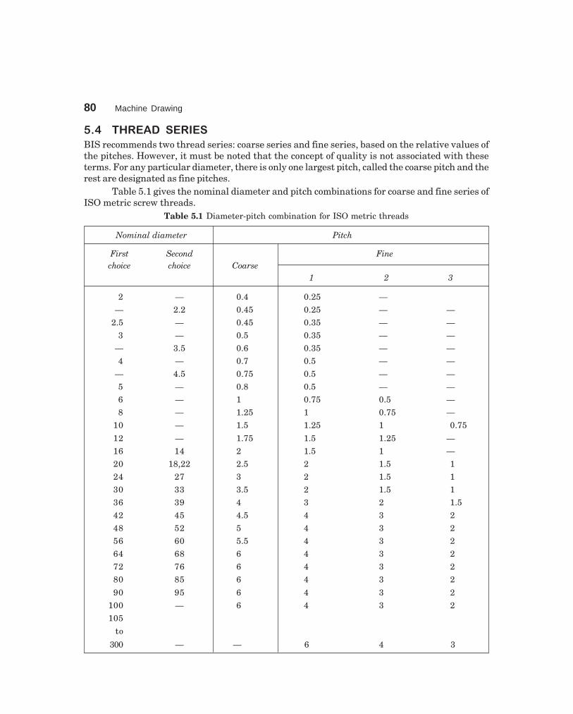
80 Machine Drawing
dharmd:\N-Design\Des5-1.pm5 Seventh Print
��# ������ ����
BIS recommends two thread series: coarse series and fine series, based on the relative values ofthe pitches. However, it must be noted that the concept of quality is not associated with theseterms. For any particular diameter, there is only one largest pitch, called the coarse pitch and therest are designated as fine pitches.
Table 5.1 gives the nominal diameter and pitch combinations for coarse and fine series ofISO metric screw threads.
Table 5.1 Diameter-pitch combination for ISO metric threads
Nominal diameter Pitch
First Second Finechoice choice Coarse
1 2 3
2 — 0.4 0.25 —
— 2.2 0.45 0.25 — —
2.5 — 0.45 0.35 — —
3 — 0.5 0.35 — —
— 3.5 0.6 0.35 — —
4 — 0.7 0.5 — —
— 4.5 0.75 0.5 — —
5 — 0.8 0.5 — —
6 — 1 0.75 0.5 —
8 — 1.25 1 0.75 —
10 — 1.5 1.25 1 0.75
12 — 1.75 1.5 1.25 —
16 14 2 1.5 1 —
20 18,22 2.5 2 1.5 1
24 27 3 2 1.5 1
30 33 3.5 2 1.5 1
36 39 4 3 2 1.5
42 45 4.5 4 3 2
48 52 5 4 3 2
56 60 5.5 4 3 2
64 68 6 4 3 2
72 76 6 4 3 2
80 85 6 4 3 2
90 95 6 4 3 2
100 — 6 4 3 2
105
to
300 — — 6 4 3
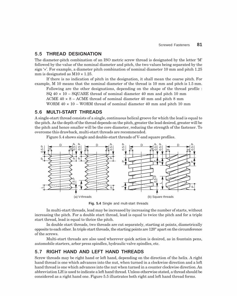
Screwed Fasteners 81
dharmd:\N-Design\Des5-1.pm5 Seventh Print
� � ����� ���������
The diameter-pitch combination of an ISO metric screw thread is designated by the letter ‘M’followed by the value of the nominal diameter and pitch, the two values being separated by thesign ‘×’. For example, a diameter pitch combination of nominal diameter 10 mm and pitch 1.25mm is designated as M10 × 1.25.
If there is no indication of pitch in the designation, it shall mean the coarse pitch. Forexample, M 10 means that the nominal diameter of the thread is 10 mm and pitch is 1.5 mm.
Following are the other designations, depending on the shape of the thread profile :SQ 40 × 10 – SQUARE thread of nominal diameter 40 mm and pitch 10 mmACME 40 × 8 – ACME thread of nominal diameter 40 mm and pitch 8 mmWORM 40 × 10 – WORM thread of nominal diameter 40 mm and pitch 10 mm
��$ ����% ����� �����
A single-start thread consists of a single, continuous helical groove for which the lead is equal tothe pitch. As the depth of the thread depends on the pitch, greater the lead desired, greater will bethe pitch and hence smaller will be the core diameter, reducing the strength of the fastener. Toovercome this drawback, multi-start threads are recommended.
Figure 5.4 shows single and double-start threads of V-and square profiles.
L
L0.5
P
P
(a) V-threads
P0.
5P
P0.
5PD
H H H HD
P0.
5P
P0.
5P
L
L0.5
P
P(b) Square threads
P0.
5P
P0.
5PD
H H H H
D
P0.
5P
P0.
5P
Fig. 5.4 Single and mult-start threads
In multi-start threads, lead may be increased by increasing the number of starts, withoutincreasing the pitch. For a double start thread, lead is equal to twice the pitch and for a triplestart thread, lead is equal to thrice the pitch.
In double start threads, two threads are cut separately, starting at points, diametricallyopposite to each other. In triple start threads, the starting points are 120° apart on the circumferenceof the screws.
Multi-start threads are also used wherever quick action is desired, as in fountain pens,automobile starters, arbor press spindles, hydraulic valve spindles, etc.
��& ��'��� ���� ��� ����� ���� �����
Screw threads may be right hand or left hand, depending on the direction of the helix. A righthand thread is one which advances into the nut, when turned in a clockwise direction and a lefthand thread is one which advances into the nut when turned in a counter clockwise direction. Anabbreviation LH is used to indicate a left hand thread. Unless otherwise stated, a thread should beconsidered as a right hand one. Figure 5.5 illustrates both right and left hand thread forms.
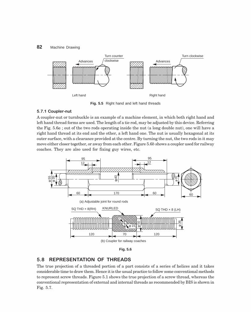
82 Machine Drawing
dharmd:\N-Design\Des5-1.pm5 Seventh Print
Advances
Turn counterclockwise
Left hand
Advances
Turn clockwise
Right hand
Fig. 5.5 Right hand and left hand threads
��&�����()!��%*(�
A coupler-nut or turnbuckle is an example of a machine element, in which both right hand andleft hand thread forms are used. The length of a tie rod, may be adjusted by this device. Referringthe Fig. 5.6a ; out of the two rods operating inside the nut (a long double nut), one will have aright hand thread at its end and the other, a left hand one. The nut is usually hexagonal at itsouter surface, with a clearance provided at the centre. By turning the nut, the two rods in it maymove either closer together, or away from each other. Figure 5.6b shows a coupler used for railwaycoaches. They are also used for fixing guy wires, etc.
60
f55
f35
1295
60 60170
f35
1295
(a) Adjustable joint for round rods
f 15
KNURLED SQ THD × 8 (LH)
f50
f36
120 12070
(b) Coupler for railway coaches
SQ THD × 8(RH)
f40
Fig. 5.6
� � ������������ ��� �����
The true projection of a threaded portion of a part consists of a series of helices and it takesconsiderable time to draw them. Hence it is the usual practice to follow some conventional methodsto represent screw threads. Figure 5.1 shows the true projection of a screw thread, whereas theconventional representation of external and internal threads as recommended by BIS is shown inFig. 5.7.

Screwed Fasteners 83
dharmd:\N-Design\Des5-1.pm5 Seventh Print
It may be noted from Fig. 5.7, that the crests of threads are indicated by a continuous thickline and the roots, by a continuous thin line. For hidden screw threads, the crests and roots areindicated by dotted lines. For threaded parts in section, hatching should be extended to the linedefining the crest of the thread. In the view from side, the threaded roots are represented by aportion of a circle, drawn with a continuous thin line, of length approximately three-quarters ofthe circumference.
The limit of useful length of screw threads is represented by a continuous thick line or adotted line, depending on its visibility. The length upto which the incomplete threads are formedbeyond the useful limit, is known as a run-out. It is represented by two inclined lines.
The simplified representation, though it saves time, is not an effective method to conveythread forms. The schematic representation, used for the purpose is shown in Fig. 5.8. In practice,the schematic representation is followed for only visible threads, i.e., for external threads andinternal threads in section. From the Fig. 5.8, it may be observed that the crest diameters, bothin external and internal threads, are drawn by thick lines. Further, the crests are represented bythin lines, extending upto the major diameter and the roots by thick lines, extending upto theminor diameter, these lines being drawn inclined with a slope equal to half the pitch.
Fig. 5.7 Conventional representation of threads

84 Machine Drawing
dharmd:\N-Design\Des5-1.pm5 Seventh Print
Fig. 5.9 illustrates the schematic representation of square threads.
DH
H
P 0.5 P
P 0.5 P
Fig. 5.8 Schematic representation of threaded parts–V-threads
P 0.5 P
0.5 PP
(a)
(b)
HH
D
Fig. 5.9 Schematic representation of threaded parts–Square threads
� � � ���������������������� � �������������!"#$
Figure 5.10 a shows the schematic representation and Figs. 5.10b and c, the conventionalrepresentation of threads in engagement.
Figure 5.10 a represents the internal threaded part in section; however, the externalthreaded one is shown unsectioned. In Figs. 5.10b and c, the external threaded parts areshown covering the internal threaded parts and should not be shown as hidden by them.
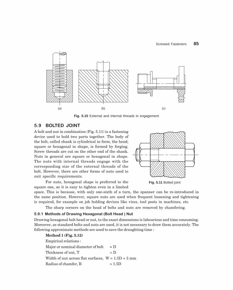
Screwed Fasteners 85
dharmd:\N-Design\Des5-1.pm5 Seventh Print
(a) (b) (c)
Fig. 5.10 External and internal threads in engagement
��+ ,����� -����
A bolt and nut in combination (Fig. 5.11) is a fasteningdevice used to hold two parts together. The body ofthe bolt, called shank is cylindrical in form, the head;square or hexagonal in shape, is formed by forging.Screw threads are cut on the other end of the shank.Nuts in general are square or hexagonal in shape.The nuts with internal threads engage with thecorresponding size of the external threads of thebolt. However, there are other forms of nuts used tosuit specific requirements.
For nuts, hexagonal shape is preferred to thesquare one, as it is easy to tighten even in a limitedspace. This is because, with only one-sixth of a turn, the spanner can be re-introduced inthe same position. However, square nuts are used when frequent loosening and tighteningis required, for example on job holding devices like vices, tool posts in machines, etc.
The sharp corners on the head of bolts and nuts are removed by chamfering.
� % � &���� ��������'��(���)�(���#�*+�#����� �,��-�
Drawing hexagonal bolt head or nut, to the exact dimensions is labourious and time consuming.Moreover, as standard bolts and nuts are used, it is not necessary to draw them accurately. Thefollowing approximate methods are used to save the draughting time :
Method 1 (Fig. 5.12)Empirical relations :Major or nominal diameter of bolt = DThickness of nut, T = DWidth of nut across flat surfaces, W = 1.5D + 3 mmRadius of chamfer, R = 1.5D
Fig. 5.11 Bolted joint
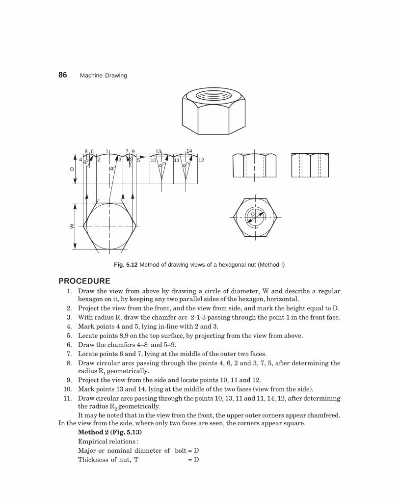
86 Machine Drawing
dharmd:\N-Design\Des5-1.pm5 Seventh Print
D
W
14
121110R
2
R2
RD
R 1 24 3
8 6 1 7 9
R1 5
13
Fig. 5.12 Method of drawing views of a hexagonal nut (Method I)
�������
1. Draw the view from above by drawing a circle of diameter, W and describe a regularhexagon on it, by keeping any two parallel sides of the hexagon, horizontal.
2. Project the view from the front, and the view from side, and mark the height equal to D.3. With radius R, draw the chamfer arc 2-1-3 passing through the point 1 in the front face.4. Mark points 4 and 5, lying in-line with 2 and 3.5. Locate points 8,9 on the top surface, by projecting from the view from above.6. Draw the chamfers 4–8 and 5–9.7. Locate points 6 and 7, lying at the middle of the outer two faces.8. Draw circular arcs passing through the points 4, 6, 2 and 3, 7, 5, after determining the
radius R1 geometrically.9. Project the view from the side and locate points 10, 11 and 12.
10. Mark points 13 and 14, lying at the middle of the two faces (view from the side).11. Draw circular arcs passing through the points 10, 13, 11 and 11, 14, 12, after determining
the radius R2 geometrically.It may be noted that in the view from the front, the upper outer corners appear chamfered.
In the view from the side, where only two faces are seen, the corners appear square.Method 2 (Fig. 5.13)Empirical relations :Major or nominal diameter of bolt = DThickness of nut, T = D

Screwed Fasteners 87
dharmd:\N-Design\Des5-1.pm5 Seventh Print
Width of the nut across corners = 2 DRadius of chamfer arc, R = 1.5 DFigure 5.13 illustrates the stages of drawing different views of a hexagonal nut,
following the above relations, which are self-explanatory.
D
D
2 D
R2 R
2
R1 R 1
R
(a)
D
(b)
Fig. 5.13 Method of drawing views of a hexagonal nut (Method II)
The above method may be followed in routine drawing work, as it helps in drawing theviews quickly.
� % . &���� �������'��(��/-����*+�#����� ,��-�
A square bolt head and nut may be drawn, showing either across flats or corners. Followingrelations may be adopted for the purpose:
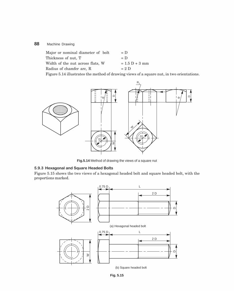
88 Machine Drawing
dharmd:\N-Design\Des5-1.pm5 Seventh Print
Major or nominal diameter of bolt = DThickness of nut, T = DWidth of the nut across flats, W = 1.5 D + 3 mmRadius of chamfer arc, R = 2 DFigure 5.14 illustrates the method of drawing views of a square nut, in two orientations.
W
D
R
D
D
R1
R
D
W
Fig.5.14 Method of drawing the views of a square nut
� % 0 ��)�(���#��� ��/-������� � �+�#��
Figure 5.15 shows the two views of a hexagonal headed bolt and square headed bolt, with theproportions marked.
2D
2 D
0.75 D L
D
(a) Hexagonal headed bolt
W
2 D
0.75 D L
D
(b) Square headed bolt
Fig. 5.15

Screwed Fasteners 89
dharmd:\N-Design\Des5-1.pm5 Seventh Print
� % 1 �������
A washer is a cylindrical piece of metal with a hole toreceive the bolt. It is used to give a perfect seating forthe nut and to distribute the tightening force uniformlyto the parts under the joint. It also prevents the nutfrom damaging the metal surface under the joint.Figure 5.16 shows a washer, with the proportionsmarked.
Figure 5.17 illustrates the views of a hexagonalheaded bolt with a nut and a washer in position.
2D
2D+
4
0.15 D2 D
DD
D0.75 D L
Fig. 5.17 A hexagonal headed bolt with a nut and a washer in position
� % � ���������!�����+�#��
�������������������������� ���������
It is provided with a square neck, which fits into a corresponding square hole in the adjacent part,preventing the rotation of the bolt (Fig. 5.18).
DD
2D
1.5D
+3
0.8 D 0.8 D
Fig. 5.18 Square headed bolt with square neck
Fig. 5.16 Washer
0.15 D
2D+
4
D + 1

90 Machine Drawing
dharmd:\N-Design\Des5-1.pm5 Seventh Print
��������� ������������� ���������
In this, a square neck provided below the head, prevents the rotation of the bolt. This type of bolt isused for fixing vices, work pieces, etc., to the machine table having T-slots (Fig. 5.19).
0.8 D 0.8 D
D 1.8
D
0.8 D 0.9 D
D
Fig. 5.19 T-headed bolt Fig. 5.20 Hook bolt
�����������������
This bolt passes through a hole in one part only, while the other part is gripped by the hookshaped bolt head. It is used where there is no space for making a bolt hole in one of the parts. Thesquare neck prevents the rotation of the bolt (Fig. 5.20).
��������!"�����
In order to facilitate lifting of heavy machinery, like electric generators, motors, turbines, etc.,eye bolts are screwed on to their top surfaces. For fitting an eye bolt, a tapped hole is provided,above the centre of gravity of the machine (Fig. 5.21).
f 0.8 D
2 D
0.4
D
2D
1.5
D
1.5D
1.5D
DD
Fig. 5.21 Eye-bolt

Screwed Fasteners 91
dharmd:\N-Design\Des5-1.pm5 Seventh Print
������������������������
It consists of cylindrical shank with threads cut on both the ends (Fig. 5.22a). It is used wherethere is no place for accommodating the bolt head or when one of the parts to be joined is too thickto use an ordinary bolt.
The stud is first screwed into one of the two parts to be joined, usually the thicker one. Astud driver, in the form of a thick hexagonal nut with a blind threaded hole is used for thepurpose. After placing the second part over the stud, a nut is screwed-on over the nut end. It isusual to provide in the second part, a hole which is slightly larger than the stud nominal diameter.Figure 5.22b shows a stud joint.
D Plate
Maincasting
D
2 D
Nut
end
Stu
d
end
Pla
inpa
rt
(a) (b)
Fig. 5.22 (a)–Stud, (b)–Stud joint
� % 2 ���������!������-��
��������#��$%�����
This is a hexagonal nut with a collar or flange, provided integral with it. This permits the use ofa bolt in a comparitively large size hole (Fig. 5.23a).
��������&�'����
It is a hexagonal nut with a cylindrical cap at the top. This design protects the end of the bolt fromcorrosion and also prevents leakage through the threads. Cap nuts are used in smoke boxes orlocomotive and steam pipe connections (Fig. 5.23b).
��������(������
It is another form of a cap nut, having a spherical dome at the top (Fig. 5.23c).
��������&�'���$����
This nut is cylindrical in shape, with holes drilled laterally in the curved surface. A tommy barmay be used in the holes for turning the nut (Fig. 5.23d). Holes may also be drilled in the upperflat face of the nut.

92 Machine Drawing
dharmd:\N-Design\Des5-1.pm5 Seventh Print
D
2.2 DD
0.25
D
a - Flanged nut
1.5 D + 3
0.5
DD
0.25
D
D
b - Cap nut
D
D0.
5D
c - Dome nut
1.8 D
0.5
D D
DD
0.1
D
0.5
D
1.8 D1.5 D
D
2 D
0.4
D
0.6 D 1.5 D
1.2 D
D
0.2D
0.2
D
d - Capstan nut
0.2D
e - Ring nut f - Wing nut
0.2
D
Fig. 5.23 Other forms of nuts
�����������������)�$%����
This nut is in the form of a ring, with slots in the curved surface, running parallel to the axis. Aspecial C-spanner is used to operate the nut. These nuts are used on large screws, where the useof ordinary spanner is inconvenient (Fig. 5.23e).
����������$%����
This nut is used when frequent removal is required, such as inspection covers, lids, etc. It isoperated by the thumb (Fig. 5.23f).
��+�& ��)� .��/"��*����.� *�� .��/"
Cap screws and machine screws are similar in shape, differing only in their relative sizes. Machinescrews are usually smaller in size, compared to cap screws. These are used for fastening twoparts, one with clearance hole and the other with tapped hole. The clearance of the unthreadedhole need not be shown on the drawing as its presence is obvious. Figure 5.24 shows differenttypes of cap and machine screws, with proportions marked.

Screwed Fasteners 93
dharmd:\N-Design\Des5-1.pm5 Seventh Print
2 D
0.6
DL DD DD
0.6
D
0.2
D
90°
0.2 D
L
Hexagonal head Flat head
0.6
D
0.4
D
0.2 D
DDL
Round head
DD
1.5 D
0.2 D
0.6
DL
Cheese head
DD
Oval head
0.6
DL
R = 2.25 D0.2 D 90°
0.4
DDD
DL 0.
75D
1.5 D
30°
Socket head
Fig. 5.24 Types of machine and cap screws
Cap screws are produced in finish form and are used on machines where accuracy andappearance are important. As cap screws are inferior to studs, they are used only on machinesrequiring few adjustments and are not suitable where frequent removal is necessary. These areproduced in different diameters, upto a maximum of 100 mm and lengths 250 mm.
Machine screws are produced with a naturally bright finish and are not heat treated. Theyare particularly adopted for screwing into thin materials and the smaller ones are threadedthroughout the length. They are used in fire-arms, jigs, fixture and dies. They are produced indifferent diameters upto a maximum of 20 mm and lengths upto 50 mm.
��+�0 ��� .��/"
These are used to prevent relative motion between tworotating parts, such as the movement of pulley on shaft.For this, a set screw is screwed into the pulley hub sothat its end-point bears firmly against the shaft (Fig. 5.25).The fastening action is by friction between the screw andthe shaft.
Set screws are not efficient and so are used onlyfor transmitting very light loads. For longer life, setscrews are made of steel and case hardened. Further,for better results, the shaft surface is suitably machinedfor providing more grip, eliminating any slippingtendency. Figure 5.26 shows different forms of setscrews. Fig. 5.25
0.25
D
D L

94 Machine Drawing
dharmd:\N-Design\Des5-1.pm5 Seventh Print
���1 ���2��'� �����'����� � ���� ��
The bolted joints, though removable in nature, are required to stay firm without becomingloose, of their own accord. However, the joints used in the moving parts of a machinery,may be subjected to vibrations. This may slacken the joint, leading to serious breakdown.To eliminate the slackening tendency, different arrangements, as discussed further, areused to lock the nuts :
� �3 ��4�56��-�
This is the most commonly used locking device. In this arrangement, a second nut, knownas lock nut is used in combination with a standard nut (Fig. 5.27a). The thickness of a locknut is usually two-thirds D, where D is the major diameter of the bolt. The lock nut isusually placed below the standard nut. To make the joint, the lock nut is first screwedtightly and then the standard nut is tightened till it touches the lock nut. Afterwards, thelocknut is then screwed back on the standard nut, which is held by a spanner. The threadsof the two nuts become wedged between the threads of the bolt.
D
1.8 D
0.8
D
D
1.5 D0.2 D
0.6
D
D
1.5 D
45°
D
1.5 D
0.5
D
D
D D
0.5
D
a – Set screw heads b – Grub screws
D
D
D
30°
D
45°
0.6 D
D
0.6D
120°
45°
D
0.8D
0.2
D
c – Set screw ends
R
Fig. 5.26
2 D
0.67
DD
(a) (b) (c)
Fig. 5.27 Lock nut

Screwed Fasteners 95
dharmd:\N-Design\Des5-1.pm5 Seventh Print
When the lock nut is first screwed into its position, the top flanks of it press againstthe bottom flanks of the bolt (Fig. 5.27b). Figure 5.27c shows the condition between theflanks of the nuts and the bolt, when the second nut is locked in position. It may be observedthat in this position, the top flanks of the top nut, press against the bottom flanks of thebolt, whereas, the bottom flanks of the lock nut press against the top flanks of the bolt.
���1�����.3 *4�56� )! ��� *
A split pin, made of steel wire of semi-circular cross-section is used for locking the nut. Inthis arrangement, the split pin is inserted through a hole in the bolt body and touching justthe top surface of the nut. Then, the ends of the pin are split open to prevent it fromcoming out while in use (Fig. 5.28).
���1�����.3 *4�56���"�!���(�
A castle nut is a hexagonal nut with a cylindrical collar turned on one end. Threads are cutin the nut portion only and six rectangular slots are cut through the collar. A split pin isinserted through a hole in the bolt body after adjusting the nut such that the hole in thebolt body comes in-line with slots. This arrangement is used in automobile works (Fig. 5.29).
SPLIT PIN, DIA 0.2 D
D
D
2 D
SPLIT PIN, DIA 0.25 D
1.25
D
D
2 D
0.3
D
0.05
D×
45°
0.45
D
30°
30°
SLOTS,WIDE 0.25 D
Fig. 5.28 Locking by split pin Fig. 5.29 Castle nut

96 Machine Drawing
dharmd:\N-Design\Des5-1.pm5 Seventh Print
� �3 1���#�7��4�56��-�
It is a hexagonal nut with a slot, cut half-way across it. After tightening the nut in the usualmanner, a set screw is used from the top of the nut, compressing the two parts. For thispurpose, the upper portion of the nut should have a clearance hole and the lower portiontapped (Fig. 5.30).
���1�����.3 *4�56� ��� .��/
In this arrangement, after the nut is tightened, a set screw in fitted in the part, adjoining thenut, so that it touches one of the flat faces of the nut. The arrangement prevents the looseningtendency of the nut (Fig. 5.31).
2 D
0.75 D
D
SCREW, DIA 0.25 DLONG 0.75 D
0.5
D0.
15D
D D
2D
D
SCREW, DIA 0.2 DLONG 0.9 D
Fig. 5.30 Wile’s lock nut Fig. 5.31 Locking by set screw
���1�$�'���7����(�
It has a cylindrical grooved collar, integrally provided at the lower end of the nut. Thiscollar fits into a corresponding recess in the adjoining part. In this arrangement, aftertightening the nut, a set screw is inserted from one end of the upper part, so that the endof the set screw enters the groove, preventing the loosening tendency of the nut (Fig. 5.32).
� �3 8�4�56��(�"$��5��'
In this, a cap nut with an integral washer and with a threaded hole in the cylindrical cap, isused. A corresponding tapped hole at the top end of the bolt is also required for the purpose.

Screwed Fasteners 97
dharmd:\N-Design\Des5-1.pm5 Seventh Print
In this arrangement, a set screw fitted through the cap and through the bolt end, preventsthe loosening tendency of the nut, when the pitches of the main nut and the set screw aredifferent (Fig. 5.33). This type of arrangement is used for fitting the propeller blades onturbine shafts.
SCREW,
DIA 0.25 D
0.25
D0.
25D
0.2
D
2 D
0.9
D
D
1.5 D
1.35 D
D
2.25 D
0.3
D
0.15
D
0.4
D0.
9D
SCREW, DIA 0.25 D
LONG 0.85 D
2 D
1.5 D
1.2 D
Fig. 5.32 Grooved nut Fig. 5.33 Locking by screw
� �3 ��4�56��(�"$��#���
A locking plate is grooved such that it fits a hexagonal nut in any position, at intervals of30° of rotation. It is fixed around the nut, by means of a machine screw, as shown in Fig.5.34.
���1�+���.3 *4�56� )� *4���"���
In this arrangement, a spring washer of either single or double coil is placed under the nutand tightened. The spring force of the washer will be acting upwards on the nut. This forcemakes the threads in the nut jammed on the bolt threads; thus preventing the nut fromloosening (Fig. 5.35).

98 Machine Drawing
dharmd:\N-Design\Des5-1.pm5 Seventh Print
0.2
D
DSCREW,
DIA 0.2 D + 2
D
2.1 D
0.12
5D
D
2 D
Fig. 5.34 Locking by plate Fig. 5.35 Locking by spring washer
���� ��������� ,���
Foundation bolts are used for fixing machines to their foundations. Foundation bolts aremade by forging from mild steel or wrought iron rods. The bolt size depends upon the sizeof the machine and the magnitude of the forces that act on them when the machine is inoperation.
For setting the bolts in position, their positions are marked and then suspended inthe holes made in the ground. Afterwards, cement concrete is filled in the space around inthe bolts. Once the concrete sets; the bolts are firmly secured to the ground.
��������6����(*��� �*�,�!�
This is the simplest form of all foundation bolts. In this, one end of the bolt is forged intoan eye and a cross piece is fixed in it. Figure 5.36 shows an eye foundation bolt that is setin concrete.
�������,�*����(*��� �*�,�!�
As the name implies, this bolt is forged in bent form and set in cement concrete. Whenmachines are to be placed on stone beds, the bolts are set in lead. Figure 5.37 shows a bentfoundation bolt that is set first in lead and then in cement concrete, resulting in a firm andstable bolt.
� �� 0���(���-� ������+�#�
This bolt consists of a tapered body, square or rectangular in cross-section, the taperededges being grooved. Figure 5.38 shows a rag foundation bolt that is set first in lead andthen in cement concrete.
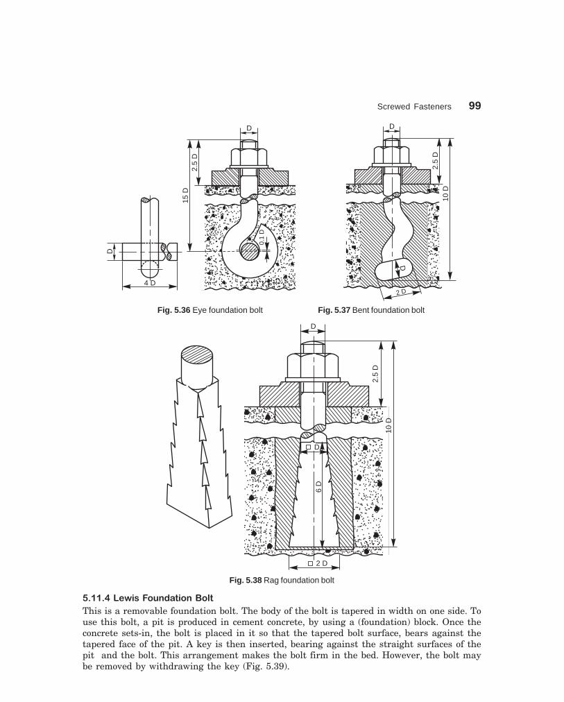
Screwed Fasteners 99
dharmd:\N-Design\Des5-1.pm5 Seventh Print
D
0.1
D
15D
2.5
D
D
4 D
D
10D
2.5
D
2 D
D
Fig. 5.36 Eye foundation bolt Fig. 5.37 Bent foundation bolt
D
2.5
D
10D
2 D
D
6D
Fig. 5.38 Rag foundation bolt
� �� 1�4�'�����-� ������+�#�
This is a removable foundation bolt. The body of the bolt is tapered in width on one side. Touse this bolt, a pit is produced in cement concrete, by using a (foundation) block. Once theconcrete sets-in, the bolt is placed in it so that the tapered bolt surface, bears against thetapered face of the pit. A key is then inserted, bearing against the straight surfaces of thepit and the bolt. This arrangement makes the bolt firm in the bed. However, the bolt maybe removed by withdrawing the key (Fig. 5.39).

100 Machine Drawing
dharmd:\N-Design\Des5-1.pm5 Seventh Print
D
10D
2.5
D
7.5
D
D
1.67 D 0.67 D
Key
Key
Fig. 5.39 Lewis foundation bolt
This type of foundation bolt is not commonly used for fixing machines. However, theprinciple is advantageously used for lifting huge stones. For this, a groove, similar to thepit is chiselled in the stone and the bolt is fitted in. The top end of the bolt may be forgedinto an eye and used for lifting purposes.
����������������(*��� �*�,�!�
It is used for fixing heavy machines. It has a rectangular slot at its bottom end, to receive acotter. For putting the bolts in position, the foundation bed is first made, providing holesfor inserting cotters. Figure 5.40 shows a cotter foundation bolt in position. A cast ironwasher (W) placed as shown, provides bearing surface for the cotter (C).
1.5
D0.
4D
DD
0.4D 1.2D 0.4D0.5D
1.2
D
THICK 0.25 D
Hand Hole
W
CC
3 D
D
Fig. 5.40 Cotter foundation bolt

Screwed Fasteners 101
dharmd:\N-Design\Des5-1.pm5 Seventh Print
THEORY QUESTIONS
5.1 What is a fastener and what is meant by fastening ?5.2 What are the various applications of screwed fasteners ?5.3 Define the following terms with respect to screw threads : (a) pitch (b) pitch diameter, (c) major
diameter, (d) minor diameter, (e) lead, (f) crest, (g) root and (h) thread angle.5.4 Distinguish between the following : (a) metric and BSW threads, (b) square and ACME threads,
(c) left hand and right hand threads and (d) pitch and lead of a thread.5.5 What is a multi-start thread and how it differs from a single start thread ?5.6 Where are multi-start threads used and why ?5.7 What is the pitch and lead in the case of a double start thread ?5.8 What type of thread is used for the screw jack and lathe lead screw and why ?5.9 How are the following threads designated as per BIS : (a) metric thread with coarse pitch, (b)
metric thread with fine pitch, (c) square thread, (d) ACME thread and (e) worm thread.5.10 Why hexagonal shape is preferred to square one for nuts ?5.11 Why are washers used in bolted joints ?5.12 What is a T-bolt and where is it used ?5.13 What is an eye-bolt and for what purpose is it used ?5.14 What is a stud bolt and where is it used ?5.15 Differentiate between the following:
(a) Bolt and screw, (b) machine screw and set screw, and (c) cap screw and machine screw.5.16 What is a set screw ? What is its function ?5.17 What are locking devices ? Where and why are they used ?5.18 What are foundation bolts and where are they used ?
DRAWING EXERCISES
5.1 Sketch the internal and external ISO metric thread profile of nominal size of 25 mm and pitch of3 mm.
5.2 Sketch the following thread profiles for a nominal diameter of 25 mm and pitch 3 mm and givetheir applications:(a) BSW thread, (b) Buttress thread (c) Square thread,(d) ACME thread and (e) Worm thread.
5.3 Sketch a double start square thread of pitch 5 mm and nominal diameter 50 mm.5.4 Sketch the half sectional view of a coupler, connecting two rods, each of 25 mm diameter.5.5 Sketch the conventional representation of the following:
(a) external threads, (b) internal threads,(c) thread in section and (d) assembled threads in section.
5.6 Give the proportions of a hexagonal nut, in terms of the nominal diameter of the bolt. Answerwith respect to the various methods followed in practice.
5.7 Draw the three views of a hexagonal headed bolt of nominal diameter 25 mm and length 100mm; with a hexagonal nut and washer.
5.8 Sketch any two types of bolts, mentioning their applications.5.9 Sketch the following forms of nuts, with proportions marked:
(a) flanged nut, (b) cap nut, (c) dome nut,(d) capstan nut, (e) wing nut and (f) ring nut.
5.10 Sketch any three types of machine screws of 10 mm diameter.5.11 Sketch any three types of cap screws of 25 mm diameter.

102 Machine Drawing
dharmd:\N-Design\Des5-1.pm5 Seventh Print
5.12 Sketch the various forms of set screw ends of size 16 mm diameter.
5.13 Sketch the two views of a castle nut, with proportions marked.
5.14 Sketch the following locking devices in position, with proportions marked, taking the bolt di-ameter as 25 mm:
(a) locking with pin, (b) locking by castle nut,
(c) locking by a nut, and (d) locking by a set screw.
5.15 Sketch neatly, giving proportionate dimensions; the following foundation bolts of diameter25 mm:
(a) eye foundation bolt, and (b) Lewis foundation bolt.

1:100 W
T
L
SLOPE, Hub
Keyway
1:100
L
0.5
T0.
5T
D
W
D
103
6����������
�� ����������
��� ��� �����
Keys, cotters and pin joints discussed in this chapter are some examples of removable(temporary) fasteners. Assembly and removal of these joints are easy as they are simple inshape. The standard proportions of these joints are given in the figures.
��� ����
Keys are machine elements used toprevent relative rotational movementbetween a shaft and the parts mountedon it, such as pulleys, gears, wheels,couplings, etc. Figure 6.1 shows the partsof a keyed joint and its assembly.
For making the joint, grooves orkeyways are cut on the surface of theshaft and in the hub of the part to bemounted. After positioning the part onthe shaft such that, both the keyways areproperly aligned, the key is driven fromthe end, resulting in a firm joint.
For mounting a part at anyintermediate location on the shaft, firstthe key is firmly placed in the keyway ofthe shaft and then the part to be mountedis slid from one end of the shaft, till it isfully engaged with the key.
Keys are classified into threetypes, viz., saddle keys, sunk keys andround keys.
����� �����������
These are taper keys, with uniform widthbut tapering in thickness on the upperside. The magnitude of the taper providedis 1:100. These are made in two forms:hollow and flat.
Fig. 6.1 Keyed joint

104 Machine Drawing
dharmd:\N-Design\Des6-1.pm5 Sixth Print
SLOPE, 1:100
L
D
W
T
SLOPE, 1:100
1:100
L
D
W
T
������������������ �� �
A hollow saddle key has a concaveshaped bottom to suit the curved surfaceof the shaft, on which it is used. Akeyway is made in the hub of themounting, with a tapered bottomsurface. When a hollow saddle key isfitted in position, the relative rotationbetween the shaft and the mounting isprevented due to the friction betweenthe shaft and key (Fig. 6.2).
����������������� �� �
It is similar to the hollow saddle key,except that the bottom surface of it isflat. Apart from the tapered keyway inthe hub of the mounting, a flat surfaceprovided on the shaft is used to fit thiskey in position (Fig. 6.3).
The two types of saddle keysdiscussed above are suitable for lightduty only. However, the flat one isslightly superior compared to the hollowtype. Saddle keys are liable to sliparound the shaft when used underheavy loads.
����� ���������
These are the standard forms of keysused in practice, and may be eithersquare or rectangular in cross-section.The end may be squared or rounded.Generally, half the thickness of the keyfits into the shaft keyway and theremaining half in the hub keyway.These keys are used for heavy duty, asthe fit between the key and the shaft ispositive.
Sunk keys may be classified as:(i) taper keys, (ii) parallel or featherkeys and (iii) woodruff keys.
����������� ������� ��
These keys are square or rectangularin cross-section, uniform in width buttapered in thickness. The bottomsurface of the key is straight and thetop surface is tapered, the magnitudeof the taper being 1:100. Hence, thekeyway in the shaft is parallel to the axis and the hub keyway is tapered (Fig. 6.1).
Fig. 6.2 Hollow saddle key
Fig. 6.3 Flat saddle key

Keys, Cotters and Pin Joints 105
dharmd:\N-Design\Des6-1.pm5 Sixth Print
A tapered sunk key may be removed by driving it out from the exposed small end. If thisend is not accessible, the bigger end of the key is provided with a head called gib. Figure 6.4shows the application of a key with a gib head. Following are the proportions for a gib head:
If D is the diameter of the shaft, then,Width of key, W = 0.25 D + 2 mmThickness of key, T = 0.67 W (at the thicker end)Standard taper = 1:100Height of head, H = 1.75 TWidth of head, B = 1.5 T
WSLOPE, 1:100
H
B
T
L
HT
B
L W
D
Fig. 6.4 Key with gib head
Table 6.1 gives the dimensions of taper sunk keys, for various shaft sizes.
Table 6.1 Proportions of taper sunk keys for various shaft sizes (contd.)
Shaft diameter (mm)
Over Upto and Width, W Thickness, Tincluding (mm) (average value)
(mm)
6 8 2 28 10 3 3
10 12 4 4
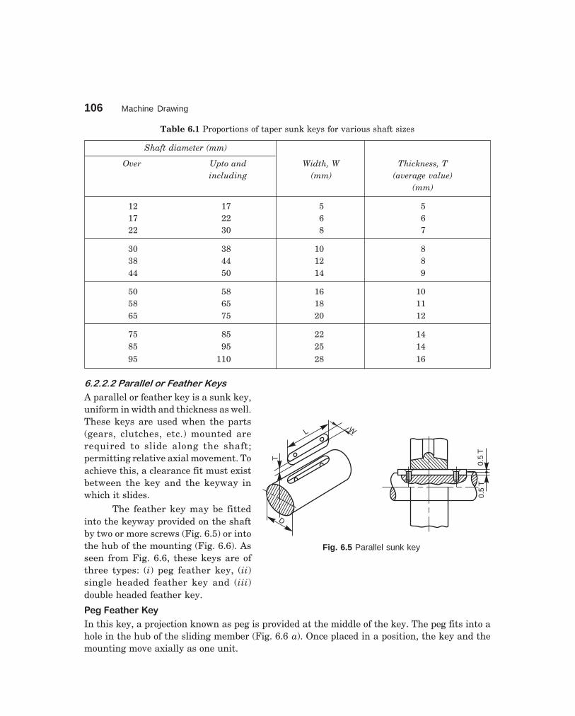
106 Machine Drawing
dharmd:\N-Design\Des6-1.pm5 Sixth Print
D
L W
T
0.5
T0.
5T
Fig. 6.5 Parallel sunk key
Table 6.1 Proportions of taper sunk keys for various shaft sizes
Shaft diameter (mm)
Over Upto and Width, W Thickness, Tincluding (mm) (average value)
(mm)
12 17 5 517 22 6 622 30 8 7
30 38 10 838 44 12 844 50 14 9
50 58 16 1058 65 18 1165 75 20 12
75 85 22 1485 95 25 1495 110 28 16
�������������� ������ ��� ��� ��
A parallel or feather key is a sunk key,uniform in width and thickness as well.These keys are used when the parts(gears, clutches, etc.) mounted arerequired to slide along the shaft;permitting relative axial movement. Toachieve this, a clearance fit must existbetween the key and the keyway inwhich it slides.
The feather key may be fittedinto the keyway provided on the shaftby two or more screws (Fig. 6.5) or intothe hub of the mounting (Fig. 6.6). Asseen from Fig. 6.6, these keys are ofthree types: (i) peg feather key, (ii)single headed feather key and (iii)double headed feather key.
�������������
In this key, a projection known as peg is provided at the middle of the key. The peg fits into ahole in the hub of the sliding member (Fig. 6.6 a). Once placed in a position, the key and themounting move axially as one unit.

Keys, Cotters and Pin Joints 107
dharmd:\N-Design\Des6-1.pm5 Sixth Print
� ���������������������
In this, the key is provided with a head at one end. The head is screwed to the hub of the partmounted on the shaft (Fig. 6.6 b).
L
W
T
0.5
T0.
5T
L0.
5T
0.5
T
(a) (b)
W
L
T
(c)
0.5
T0.
5T
W
T
Fig. 6.6 Feather keys
�����������������������
In this, the key is provided with heads on both ends. These heads prevent the axial movementof the key in the hub. Here too, once placed in position, the key and the mounting move as oneunit (Fig. 6.6 c).
������������ �
Splines are keys made integral with the shaft, by cutting equi-spaced grooves of uniform cross-section. The shaft with splines is called a splined shaft. The splines on the shaft, fit into thecorresponding recesses in the hub of the mounting, with a sliding fit, providing a positive driveand at the same time permitting the latter to move axially along the shaft (Fig. 6.7).
W
D1
D2
W
D2
D1
Fig. 6.7 Splined shaft and hub
Table 6.2 gives the proportions for splined shafts of various sizes.
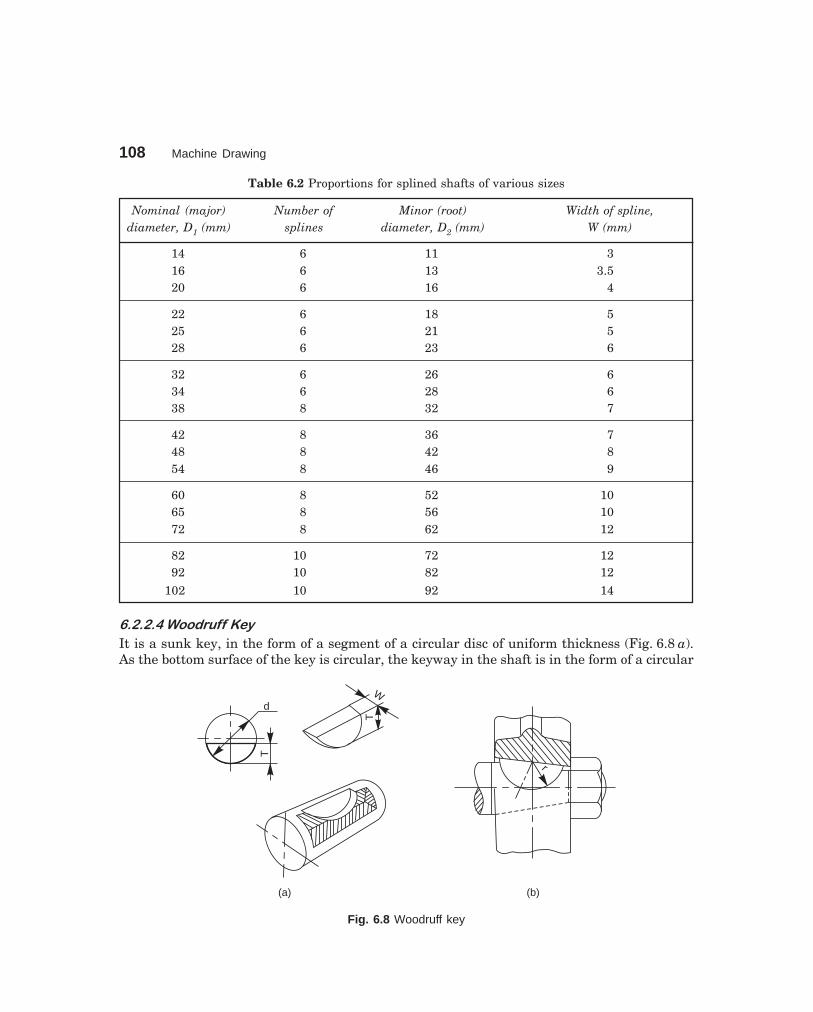
108 Machine Drawing
dharmd:\N-Design\Des6-1.pm5 Sixth Print
Table 6.2 Proportions for splined shafts of various sizes
Nominal (major) Number of Minor (root) Width of spline,diameter, D1 (mm) splines diameter, D2 (mm) W (mm)
14 6 11 316 6 13 3.520 6 16 4
22 6 18 525 6 21 528 6 23 6
32 6 26 634 6 28 638 8 32 7
42 8 36 748 8 42 854 8 46 9
60 8 52 1065 8 56 1072 8 62 12
82 10 72 1292 10 82 12
102 10 92 14
���������������� �� �
It is a sunk key, in the form of a segment of a circular disc of uniform thickness (Fig. 6.8 a).As the bottom surface of the key is circular, the keyway in the shaft is in the form of a circular
d
T
T
W
(a) (b)
r
Fig. 6.8 Woodruff key

Keys, Cotters and Pin Joints 109
dharmd:\N-Design\Des6-1.pm5 Sixth Print
recess to the same curvature as the key. A keyway is made in the hub of the mounting, in theusual manner. Woodruff key is mainly used on tapered shafts of machine tools and automobiles.Once placed in position, the key tilts and aligns itself on the tapered shaft (Fig. 6.8 b). Thefollowing are the proportions of woodruff keys:
If D is the diameter of the shaft,Thickness of key, W = 0.25 DDiameter of key, d = 3 WHeight of key, T = 1.35 WDepth of the keyway in the hub, T1 = 0.5 W + 0.1 mmDepth of keyway in shaft, T2 = 0.85 W
������ �!������ ��
Round keys are of circular cross-section, usually tapered (1:50) along the length. A round keyfits in the hole drilled partly in the shaft and partly in the hub (Fig. 6.9). The mean diameter ofthe pin may be taken as 0.25 D, where D is shaft diameter. Round keys are generally used forlight duty, where the loads are not considerable.
d
1:50
L
D
(a)L
(b)
d
DD
Fig. 6.9 Round key
��� ���� �����
A cotter is a flat wedge shaped piece, made of steel. It is uniform in thickness but tapering inwidth, generally on one side; the usual taper being 1:30. The lateral (bearing) edges of thecotter and the bearing slots are generally made semi-circular instead of straight (Fig. 6.10).

110 Machine Drawing
dharmd:\N-Design\Des6-1.pm5 Sixth Print
This increases the bearing area and permits drilling while making the slots. The cotter islocked in position by means of a screw as shown in Fig. 6.11.
Cotter joints are used to connect two rods, subjected to tensile or compressive forcesalong their axes. These joints are not suitable where the members are under rotation. Thefollowing are some of the commonly used cotter joints:
Fig. 6.10 Cotter and the bearing slot Fig. 6.11 Locking arrangement of cotter
(b)(a)
0.1 D 0.1 D
1.3 D 0.4 D0.1 D 0.1 D
0.1 D
8 D
0.1 D
D
1.3 D0.4 D
2.5
D
1.3
D 4D
1.3 D1.3 D 1.3 D1.3 D 0.1 D
0.3
D0.
3D
(c)
Fig. 6.12 Cotter joint with sleeve

Keys, Cotters and Pin Joints 111
dharmd:\N-Design\Des6-1.pm5 Sixth Print
����� � !!�"�� #�!�$#!%�����&�
This is the simplest of all cotter joints, used for fastening two circular rods. To make the joint,the rods are enlarged at their ends and slots are cut. After keeping the rods butt against eachother, a sleeve with slots is placed over them. After aligning the slots properly, two cotters aredriven-in through the slots, resulting in the joint (Fig. 6.12). The rod ends are enlarged to takecare of the weakening effect caused by the slots.
The slots in the rods and sleeve are made slightly wider than the width of cotter. Therelative positions of the slots are such, that when a cotter is driven into its position, it permitswedging action and pulls the rod into the sleeve.
������� !!�"�� #�!�$#!%�� '��!������(#) !�����
This joint is also used to fasten two circular rods. In this, the rod ends are modified instead ofusing a sleeve. One end of the rod is formed into a socket and the other into a spigot (Fig. 6.13)and slots are cut. After aligning the socket and spigot ends, a cotter is driven-in through theslots, forming the joint.
Socket end
Spigot end
(a)
0.3 D
1.25
D1.
25D
4D
1.8
D
D
1.25
D1.
25D
DD
1.8
D1.
8D
2.5
D2.
5D
3.25 D 0.5 D
33
1.3 D
SLOPE,1:30
0.8 D 1.2 D 1.1 D
4.25 D(b)
Fig. 6.13 Cotter joint with socket and spigot ends
������� !!�"�� #�!�$#!%���*#+
This joint is generally used to connect two rods of square or rectangular cross-section. To makethe joint, one end of the rod is formed into a U-fork, into which, the end of the other rod fits in.

112 Machine Drawing
dharmd:\N-Design\Des6-1.pm5 Sixth Print
When a cotter is driven-in, the friction between the cotter and straps of the U-fork, causes thestraps to open. This is prevented by the use of a gib.
A gib is also a wedge shaped piece of retangular cross-section with two rectangularprojections called lugs. One side of the gib is tapered and the other straight. The tapered sideof the gib bears against the tapered side of the cotter such that, the outer edges of the cotterand gib as a unit are parallel. This facilitates making of slots with parallel edges, unlike thetapered edges in case of ordinary cotter joint. Further, the lugs bearing against the outersurfaces of the fork, prevents the opening tendency of the straps.
Figure 6.14 shows a cotter joint with a gib. For making the joint, first the gib is placed inposition and then the cotter is driven-in.
GibCotter
(a)
0.1 D
0.5D0.1D0.1DD
3.8 D
1.5 D 1.1 D
0.5 D
0.4D
3D
2D D
D
SLOPE, 1:30
(b)
D
0.3 D
4D
Fig. 6.14 Cotter joint with a gib
��, ���� �����
In a pin joint, a pin is used to fasten two rods that are under the action of a tensile force;although the rods may support a compressive force if the joint is guided. Some pin joints suchas universal joints, use two pins and are used to transmit power from one rotating shaft toanother (the universal joint is discussed under Chapter 7). A pin joint permits a small amount

Keys, Cotters and Pin Joints 113
dharmd:\N-Design\Des6-1.pm5 Sixth Print
of flexibility or one rod may be positioned at an angle (in the plane containing the rods) withrespect to the other rod, after providing suitable guides.
Unlike in cotter joints, the pin in a pin joint is not driven-in with a force fit, but isinserted in the holes with a clearance fit. The pin is held in position, by means of a taper pin ora split pin provided at its end.
��,�� ���'����� #�!
A knuckle joint is a pin joint used to fasten two circular rods. In this joint, one end of the rod isformed into an eye and the other into a fork (double eye). For making the joint, the eye end ofthe rod is aligned into the fork end of the other and then the pin is inserted through the holesand held in position by means of a collar and a taper pin (Fig. 6.15). Once the joint is made, therods are free to swivel about the cylindrical pin.
Knuckle joints are used in suspension links, air brake arrangement of locomotives, etc.
Eye
Fork endCollarKnuckle pin
Taper pin
(a)
0.25
D
1.2
D
1.2
D
D
4D D
4 D 4 D
1.5 D
D
D
0.75
D
1.5 D
1.35 DD
(b)
0.5
D
0.5
D
1.2 D
Fig. 6.15 Knuckle joint
THEORY QUESTIONS
6.1 What is a key and what for is it used?6.2 What is the amount of taper usually provided on the face of a key?6.3 What is the difference between a saddle key and a sunk key?

114 Machine Drawing
dharmd:\N-Design\Des6-1.pm5 Sixth Print
6.4 What is the purpose of providing a head at the end of a taper sunk key ?6.5 Give the proportions of a gib head, in terms of shaft diameter.6.6 Where and why the woodruff key is used?6.7 What is a feather key and what are its uses?6.8 What is a cotter and when is it used? What is the purpose of using a gib along with a cotter in a
cotter joint?6.9 What is a knuckle joint and where is it used? What is the difference between the eye end and fork
end of a knuckle joint?6.10 Why clearances are provided in cotter joints ? Differentiate between cotter joint and pin joint?
DRAWING EXERCISES
6.1 Sketch the various methods of fitting a feather key in position.6.2 Sketch the following types of keys in two views, as fitted in position between a shaft and the
mounting. Choose the shaft diameter as 30 mm and the hub diameter of the mounting as 60 mm:(a) hollow saddle key, (b) flat saddle key,(c) taper sunk key, (d) single headed feather key,(e) splines and (f) woodruff key.
6.3 Draw the sectional view from the front, and view from the side of a cotter joint with sleeve usedto connect two rods of 50 mm diameter each.
6.4 Draw the half sectional view from the front, with top half in section and the view from the side ofa cotter joint with socket and spigot ends, to connect two rods of 50 mm diameter each.
6.5 Two square rods of side 50 mm each, are connected by a cotter joint with a gib. Sketch thefollowing views of the assembly :(a) half sectional view from the front and (b) view from the side.

115
7���������� ��
��� � ��������
Shaft couplings are used to join or connect two shafts in such a way that when both the shaftsrotate, they act as one unit and transmit power from one shaft to the other. Shafts to beconnected or coupled may have collinear axes, intersecting axes or parallel axes at a smalldistance. Based on the requirements, the shaft couplings are classified as: (i) rigid couplings,(ii) flexible couplings, (iii) loose or dis-engaging couplings and (iv) non-aligned couplings.
��� ������ ���� ��
Rigid shaft couplings are used for connecting shafts having collinear axes. These are furthersub-classified into muff or sleeve couplings and flanged couplings.
����� �������������� �������� !
This is the simplest of all couplings. It consists of a sleeve called muff, generally made of castiron, which is fitted over the ends of the shafts to be connected. After properly aligning thekeyways in the shafts and sleeve, a sunk key is driven-in; thus making the coupling. Instead ofa single key running the entire length of the sleeve, it is desirable to use two keys, which maybe inserted from the outer ends of the sleeve; thus overcoming the possible mis-alignmentbetween the keyways. The following are the types of muff couplings:
����������������� ������
In this, the ends of the two shafts to be coupled butt against each other, with the sleeve keyedto them, as discussed above (Fig.7.1).
�������������������� �� ������
In this, the ends of the shafts overlap each other for a short length. The taper provided in theoverlap prevents the axial movement of the shafts. Here too, after placing the muff over theoverlapping ends of the shafts, a saddle key(s) is(are) used to make the coupling (Fig. 7.2).
������������������ ������
In this, the muff is split into two halves and are recessed. A number of bolts and nuts are usedto connect the muff halves and the recesses provided accommodate the bolt heads and nuts.
For making the coupling, a sunk key is first placed in position and then the muff halvesare joined by bolts and nuts (Fig. 7.3). This type of coupling is used for heavy duty work, sinceboth the key and friction grip transmit the power (torque).

116 Machine Drawing
dharmd:\N-Design\Des7-1.pm5 Seventh Print
(a)
1.5D
D
3 D
(b)
SUNK KEY,SLOPE 1 : 100
T
2.5 D
W
Fig. 7.1 Butt-muff coupling
(a)
1.25 D DR = 0.1D
1.4
D
D
3
3.5 D4.2 D
SADDLE KEY, SLOPE 1:100
2.5 D
W
T
(b)
Fig. 7.2 Half-lap muff coupling

Shaft Couplings 117
dharmd:\N-Design\Des7-1.pm5 Seventh Print
(a)
D
0.9 D0.9 D 0.9 D0.9 D
D 1.25 D
3.25 D
(b)
SUNK KEY, W × T
0.5D
0.5D
0.25 D + 2
0.5D0.5D
1.75D
2.75
D
Fig. 7.3 Split-muff coupling
����� ��"� �#�������� !
These are the standard forms of couplings, most extensively used. In a flanged coupling, flangesare either fitted or provided at the ends of shafts. The flanges are fastened together by meansof a number of bolts and nuts. The number and size of the bolts depend upon the power to betransmitted and hence, the shaft diameter.
����������������� �����������������������������
In this, two flanges are keyed, one at the end of each shaft, by means of sunk keys (Fig. 7.4).For ensuring correct alignment, a cylindrical projection may be provided on one flange whichfits into the corresponding recess in the other.
In the design shown in figure, the bolt heads and nuts are exposed and liable to causeinjury to the workman. Hence, as a protection, the bolt heads and nuts may be covered byproviding an annular projection on each flange. A flanged coupling, using these flanges iscalled a protected flanged coupling (Fig. 7.5).
��������� ������������� ������
Couplings for marine or automotive propeller shafts demand greater strength and reliability.For these applications, flanges are forged integral with the shafts. The flanges are joinedtogether by means of a number of headless taper bolts (Fig. 7.6).

118 Machine Drawing
dharmd:\N-Design\Des7-1.pm5 Seventh Print
T
D
W
1.75 D
5
D
D
0.5D 0.5
D
4 HOLES, DIA 0.3 DEQUI - SP
(a)D
2D
1.5 D
0.3
D
5
D D
0.5 D 0.5 D
D2D
4 D
(b)
3 D
SUNK KEY, W × T
Fig. 7.4 Flanged coupling
T
0.3 D
3 D
4.5
D4
D
2 3
0.5 D0.5 D
0.8 D 0.8 D
1.5 D 1.5 D
2D D
WW
Fig. 7.5 Protected flanged coupling
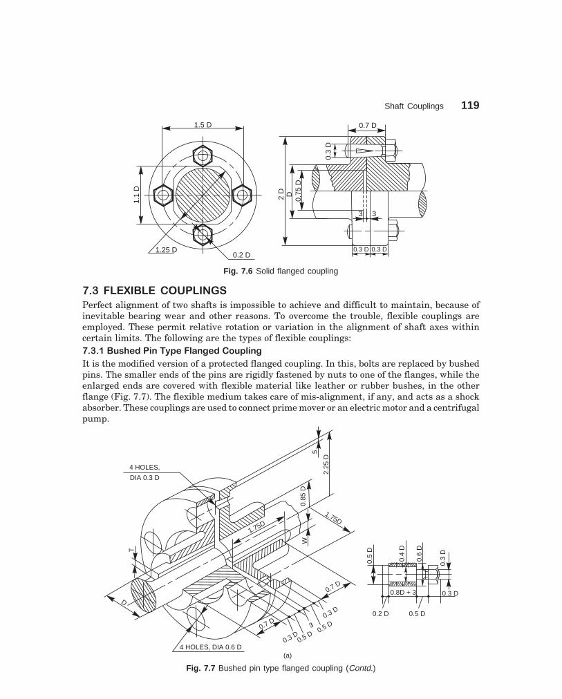
Shaft Couplings 119
dharmd:\N-Design\Des7-1.pm5 Seventh Print
0.2 D
1.5 D
1.25 D
1.1
D
0.7 D
0.3
D
3 3
0.3 D 0.3 D
2D D
0.75
D
Fig. 7.6 Solid flanged coupling
��$� ��%&�'�%� ���� ��
Perfect alignment of two shafts is impossible to achieve and difficult to maintain, because ofinevitable bearing wear and other reasons. To overcome the trouble, flexible couplings areemployed. These permit relative rotation or variation in the alignment of shaft axes withincertain limits. The following are the types of flexible couplings:��$���'�!(�#�����)�����"� �#��������
It is the modified version of a protected flanged coupling. In this, bolts are replaced by bushedpins. The smaller ends of the pins are rigidly fastened by nuts to one of the flanges, while theenlarged ends are covered with flexible material like leather or rubber bushes, in the otherflange (Fig. 7.7). The flexible medium takes care of mis-alignment, if any, and acts as a shockabsorber. These couplings are used to connect prime mover or an electric motor and a centrifugalpump.
D
T
1.75D
W
1.75D
0.85
D
4 HOLES, DIA 0.6 D
0.7 D
0.3 D0.5 D
0.5 D0.3 D
3
0.7 D
4 HOLES,
DIA 0.3 D
5
2.25
D
(a)
0.5
D
0.4
D
0.6
D
0.3
D
0.2 D 0.5 D
0.8D + 3 0.3 D
Fig. 7.7 Bushed pin type flanged coupling (Contd.)

120 Machine Drawing
dharmd:\N-Design\Des7-1.pm5 Seventh Print
D
0.6
D
0.5
D
4 BOLTS,0.3 D
5
0.5 D0.5 D0.5 D0.5 D
D1.
7D
4.5
D
3.5
D
1.5 D 1.5 D
0.8 D0.8 D
3
T
(b)
WW
Fig. 7.7 Bushed pin type flanged coupling
��$�� ��*���!!�����������
This consists of a compressible steel sleeve which fits on to the ends of the shafts to be coupled.The sleeve corresponds to the shaft diameter and its outer surface is of double conical form.The sleeve has one through cut longitudinally and five other cuts, equi-spaced, but runningalternately from opposite ends to about 85% of its length; making it radially flexible.
The two flanges used have conical bores and are drawn towards each other by means ofa number of bolts and nuts, making the sleeve firmly compressed onto the shafts. Here, thefriction between the shafts and sleeve assists power transmission and the bolts do not take anyload. Because of the presence of flexible sleeve, the coupling takes care of both axial and angularmis-alignment of shafts (Fig. 7.8).
��+� ���,% ���� �� ���� ��
Disengaging couplings are used when power transmission from one shaft to another isintermittent. With this, the shafts can be engaged or disengaged as and when required, evenduring rotation. A dis-engaging coupling in general consists of one part firmly fixed to thedriving shaft and another one mounted with provision for sliding over the driven shaft.The part that is mounted on the driven shaft, can be made to slide at will to engage or dis-engage from the rotating driving shaft. The following are the examples of dis-engagingcouplings.
��+�����"-��������
In this, each flange has a number of identical claws which engage into the correspondingrecesses in the flange. One flange is firmly fitted to the driving shaft by means of a taper sunkkey. The other one is placed over the driven shaft by two feather keys, so that it can slidefreely on it. The sliding flange has a groove on the boss, into which the forked end of a leverfits. By operating the lever, the sliding flange may be moved so as to engage with or dis-engage from the fixed flange (Fig. 7.9). This type of coupling is generally used on slowspeed shafts.
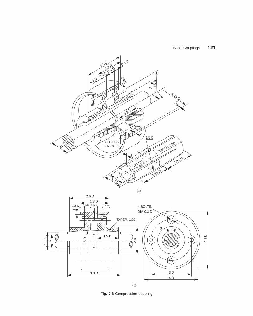
Shaft Couplings 121
dharmd:\N-Design\Des7-1.pm5 Seventh Print
2
5
0.3 D0.3 D 0.3 D 0.3 D
1.8 D
2.6 D
TAPER, 1:30
3.3 D
1.5 D
1.5
D
1.3
DD 2
D
3
4.3
D4 BOLTS,
DIA-0.3 D
3 D
4 D
(b)
D
1.5D
D 1.5
D
0.5 D2.15 D
5
7
4 HOLESDIA - 0.3 D
5
2
2.6D
1.8D 0.3
D
0.3D
0.3D 0.6
D
3
1.65 D
1.65 D
1:30TAPER
TAPER 1:30
1.5 D
1:3 DD
(a)
Fig. 7.8 Compression coupling

122 Machine Drawing
dharmd:\N-Design\Des7-1.pm5 Seventh Print
1.25 D 2.25 D
1.75 D
1.6 D 2.5 D
3
2 2
0.6 D 5
0.3 D0.25 D0.25 D 0.25 D
1.75 D
1.2 D5
1.75
D
1.25
D1.
4D
2D
60°
T W
60°
2.5 D1.5 D
DD
Fig. 7.9 Claw coupling
��+���������������
In this, two shafts may be coupled together by means of two flanges with conical surfaces (onthe inside of one and on the outside of the other) by virtue of friction. Here too, one flange isfirmly fitted to the driving shaft by means of a taper sunk key, whereas the other slides freelyover a feather key fitted to the driven shaft. The sliding flange may be moved by means of aforked lever fitted into the groove provided on it. (Fig. 7.10).
25 888
1.5 D
1.8 D
12 14 14 1688
6D
2.4
D1.
6D
6.5
D6.
8D
2020
Sunk key
D1.
8D
2.4
D
7.2
D
10
Featherkey
Fig. 7.10 Cone coupling

Shaft Couplings 123
dharmd:\N-Design\Des7-1.pm5 Seventh Print
��.� � ,���� %�� ���� ��
Non-aligned couplings are used to transmit power between two shafts which are not coaxial.The following are the examples of non-aligned couplings:
��.��������!"��������� �/���0�1!�2���34
It is a rigid coupling that connects two shafts, whose axes intersect if extended. It consists oftwo forks which are keyed to the shafts. The two forks are pin joined to a central block, whichhas two arms at right angle to each other in the form of a cross (Fig. 7.11). The angle betweenthe shafts may be varied even while the shafts are rotating.
1.1 D 1.1 D
1.8
D
D
1.7 D
0.25
D
0.8 D
DD
2.6 D
1.1 D
D1.
8D
2.2
D
Taper Sunk Key
D0.6 D
0.5
D0.
25D
(b)
0.6D
PIN,DIA5
D
D
0.25
D
D1.8 D
0.25
D 1.6
D 1.1 D
0.6 D
0.8 D
0.5
D
2.6 D
0.6 D
2.2
D0.
5D
0.6 D
1.1 D
1.1 D
0.6 D
1.1 D1.1 D
2.2
D
0.8 D
(a)
3.6
D
0.5
D
Fig. 7.11 Universal coupling
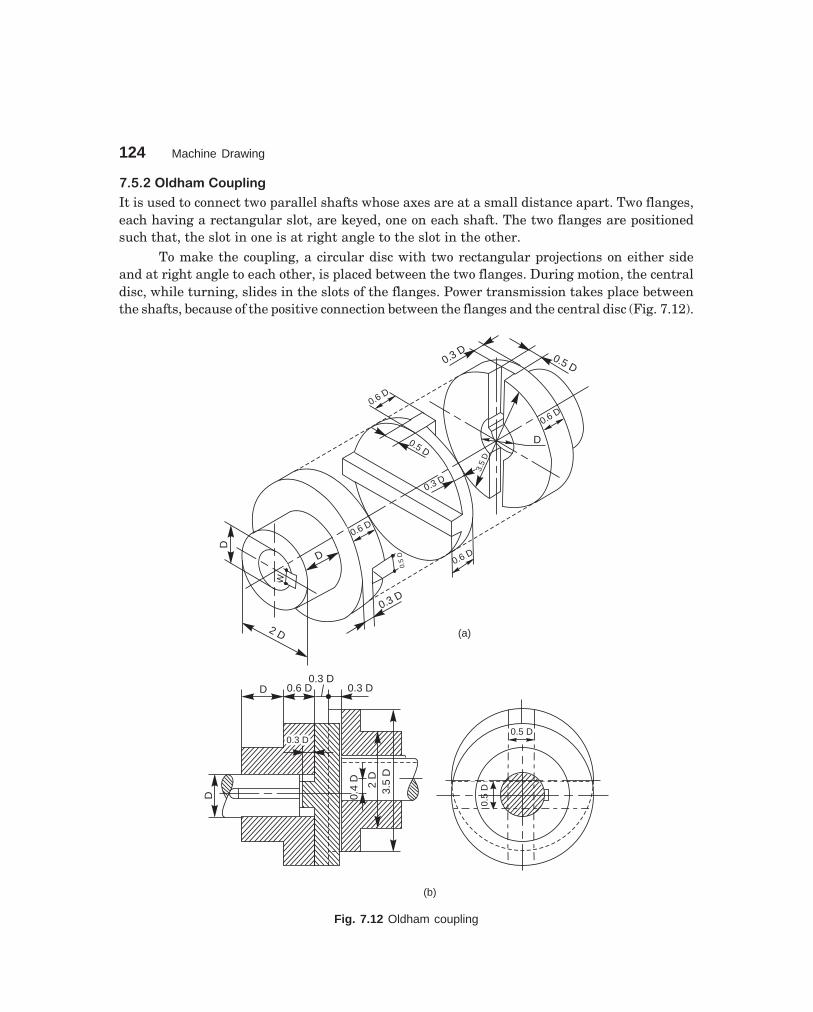
124 Machine Drawing
dharmd:\N-Design\Des7-1.pm5 Seventh Print
��.�����#("*��������
It is used to connect two parallel shafts whose axes are at a small distance apart. Two flanges,each having a rectangular slot, are keyed, one on each shaft. The two flanges are positionedsuch that, the slot in one is at right angle to the slot in the other.
To make the coupling, a circular disc with two rectangular projections on either sideand at right angle to each other, is placed between the two flanges. During motion, the centraldisc, while turning, slides in the slots of the flanges. Power transmission takes place betweenthe shafts, because of the positive connection between the flanges and the central disc (Fig. 7.12).
2 D
D
D
W
0.6 D
0.3 D
0.6 D
0.5
D
0.3 D
0.5 D
0.6D
D
0.6D
3.5
D
0.3 D 0.5 D
(a)
D
0.3 D0.3 D
0.4
D 2D
3.5
D
D 0.6 D0.3 D
0.3 D
(b)
0.5 D
0.5
D
Fig. 7.12 Oldham coupling

Shaft Couplings 125
dharmd:\N-Design\Des7-1.pm5 Seventh Print
��.�$ ��!(�����������
One of the most commonly used flexible couplings now-a-days is the cushion coupling. The H.Prating of these couplings for various speeds, range from 0.2 to 450.
The tyre of the coupling is made of natural and synthetic rubber, impregnated withcanvas or rayon. The hubs are made of C I or steel (Fig. 7.13).
R2 KEYS,
W × T
D 0.2
D
0.2 D
0.2 D 0.5 D
2D
1.2 D0.5 D
3 0.2 D 0.2 D 3
0.5 D
D
1.5
D
1.5
D
2.75 D
6, 0.25 D SOCKET
HD CAP SCR EQUI-SP3 D
4 D
Fig. 7.13 Cushion coupling
THEORY QUESTIONS
7.1 What is a shaft coupling?
7.2 Name different types of shaft couplings. What is the basis, on which shaft couplings are classi-fied?
7.3 Name three types of rigid shaft couplings. State why they are called rigid.
7.4 State where and why split-muff coupling is used in preference to solid muff coupling.
7.5 What is a flange coupling and why is it so named ?
7.6 Why are the annular recesses provided at the side of flanges in a protected flange coupling?
7.7 How flanges are made in a marine coupling?
7.8 What are the uses of a flexible coupling ?
7.9 What is a universal coupling? Why it is so named?
7.10 Describe how a compression coupling transmits power from one shaft to another.
7.11 Differentiate between:
(a) Butt-muff coupling and half-lap muff coupling,
(b) Rigid coupling and flexible coupling,
(c) Flange coupling and flexible coupling,
(d) Bushed pin type flange coupling and cushion coupling, and
(e) Cone coupling and claw coupling.

126 Machine Drawing
dharmd:\N-Design\Des7-1.pm5 Seventh Print
DRAWING EXERCISES
7.1 Sketch the sectional view from the front and view from the side of a butt-muff coupling; indicatingproportions for connecting two shafts, each of diameter 30 mm.
7.2 Draw (a) half sectional view from the front, top half in section and (b) half sectional view fromthe side, left half in section, of a split-muff coupling, indicating proportions to connect two shafts,each of diameter 50 mm.
7.3 Draw (a) half sectional view from the front, top half in section and (b) view from the side of arigid flange coupling to connect two shafts, each of diameter 30 mm. Sketch the above views forthe protected type of flange coupling.
7.4 Sketch the required views, indicating the proportions of a solid flange coupling used in marineengines to connect two shafts, each of diameter 60 mm.
7.5 Draw (a) half sectional view from the front, top half in section and (b) view from the side of abushed pin type flange coupling, indicating proportions to connect two shafts, each of diameter30 mm.
7.6 Sketch the required views, indicating proportions of (a) compression-muff coupling, (b) conecoupling and (c) claw coupling, to connect two shafts, each of diameter 30 mm.
7.7 Draw (a) sectional view from the front and (b) view from the side of a universal coupling, indicatingproportions, to connect two shafts, each of diameter 40 mm.
7.8 Sketch the required views of (a) oldham coupling and (b) cushion coupling, indicating proportions,used to connect two shafts, each of diameter 30 mm.
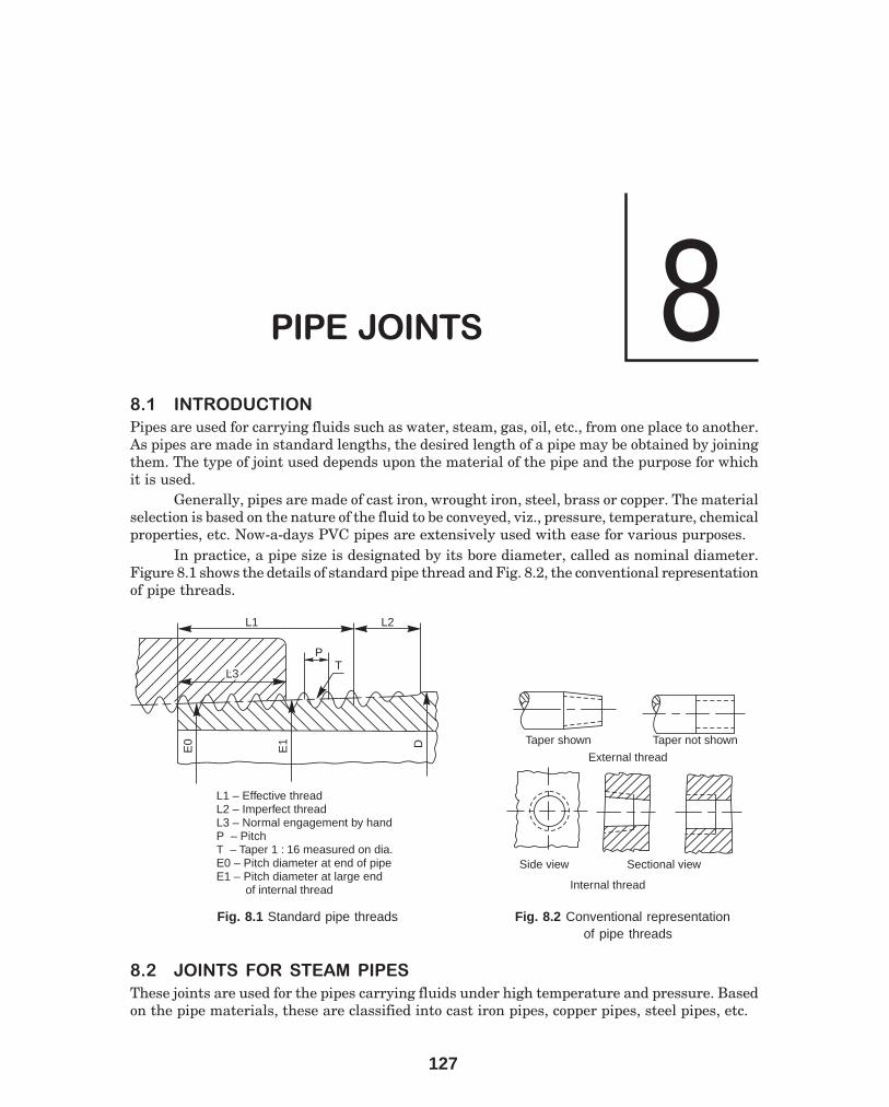
127
8����������
�� ��� ��������
Pipes are used for carrying fluids such as water, steam, gas, oil, etc., from one place to another.As pipes are made in standard lengths, the desired length of a pipe may be obtained by joiningthem. The type of joint used depends upon the material of the pipe and the purpose for whichit is used.
Generally, pipes are made of cast iron, wrought iron, steel, brass or copper. The materialselection is based on the nature of the fluid to be conveyed, viz., pressure, temperature, chemicalproperties, etc. Now-a-days PVC pipes are extensively used with ease for various purposes.
In practice, a pipe size is designated by its bore diameter, called as nominal diameter.Figure 8.1 shows the details of standard pipe thread and Fig. 8.2, the conventional representationof pipe threads.
DE1
E0
L3L3T
L1 L2
L1 – Effective threadL2 – Imperfect threadL3 – Normal engagement by handP – PitchT – Taper 1 : 16 measured on dia.E0 – Pitch diameter at end of pipeE1 – Pitch diameter at large end
of internal thread
P
Taper shown Taper not shown
External thread
Side view Sectional view
Internal thread
Fig. 8.1 Standard pipe threads Fig. 8.2 Conventional representationof pipe threads
�� ������ �� � ����� ����
These joints are used for the pipes carrying fluids under high temperature and pressure. Basedon the pipe materials, these are classified into cast iron pipes, copper pipes, steel pipes, etc.

128 Machine Drawing
dharmd:\N-Design\Des8-1.pm5 Seventh Print
���� ��������������������������
Cast iron pipes are produced with flanges, integral with the pipe ends. To ensure alignmentand seating, the flange faces are machined. Further, to make the joint air tight, a thin disc ofpacking material, such as rubber or leather, is placed between the flanges and are joined bymeans of a number of bolts and nuts (Fig. 8.3a).
If greater strength is required for high pressure duty, the thickness of the pipe may beslightly increased near the flange (Fig. 8.3b). For larger diameter pipes, under high pressures,the flanges are strengthened by means of cast ribs. (Fig. 8.3c).
25 253
f13
0
f22
0
(a)
4 BOLTS, M18
f 100
f 170
25
5
f12
5
4 BOLTS, M18
f 100
f 190
(b)
2540 40
f13
5
f25
0
Fig. 8.3 Cast iron pipe joints (Contd.)

Pipe Joints 129
dharmd:\N-Design\Des8-1.pm5 Seventh Print
(c)
f 170
f 10012
25
5
f12
5
25 80
f22
0
80
4 BOLTS, M18
Fig. 8.3 Cast iron pipe joints
����������������������������
Copper pipes are usually solid drawn. Separate flanges, made of gunmetal for smaller pipesand steel or wrought iron for larger pipes are attached to the pipe ends by brazing. The joint isobtained by means of a number of bolts and nuts (Figs. 8.4a and b).
(a)
12 1234 BOLTS, M9
6 6
f56
f68
f92
f11
2
(c)
12 1234 BOLTS, M9
f56
f80
f10
0
f50
(b)
f50
Fig. 8.4 Copper pipe joints

130 Machine Drawing
dharmd:\N-Design\Des8-1.pm5 Seventh Print
Copper pipes are used as feed and drain pipes in steam engines, as steam pipes inmarine engines and also for refrigeration coils.
Figure 8.4c shows the joint, with flanges strengthened by providing hubs, ensuring betterhold on the pipes.
���������������� ��!"#���������$����%������
In the simplest form of a joint, as shown in Fig. 8.5a, flanges are formed at the end of eachpipe, which are fastened by means of bolts and nuts. This joint is similar to a cast iron flangedjoint.
In the other form of a joint, flanges made of cast iron or cast steel are screwed onto theends of solid drawn wrought iron or steel pipes. The flanges are fastened by means of bolts andnuts (Fig. 8.5b).
Wrought iron pipes are made in relatively smaller sizes, which are usually galvanisedall over. Solid drawn steel pipes have greater strength and are used for carrying fluids underhigh pressure.
(a)
2525
M11
2
45 45
4 BOLTS, M18
f12
0
f18
0
f14
0
f20
0
f11
2f10
0
(b)
66
f10
0
f11
2f
160
f20
0
4 BOLTS, M16
Fig. 8.5 Wrought iron and steel pipe joints
��� ������ �� �&'� ��(��� ����
Hydraulic pipes are used to carry liquids such as water, oil, sewage, etc., under pressure but atnormal temperatures. Depending upon the purpose, these pipes may be laid either above theground or beneath it. The following are some of the common types of hydraulic joints:

Pipe Joints 131
dharmd:\N-Design\Des8-1.pm5 Seventh Print
������)*�����$���"��������
This type of joint is used for underground pipelines of large diameters. In this, one end of apipe is made into a socket and the other end into a spigot. After placing the spigot end into thesocket, the space between them is filled-in, partly by rope (jute or coir) and the remaining bymolten lead (Fig. 8.6).
Because of the flexible nature of the joint, it adapts itself to small changes in level due tosettlement of earth.
Socket end
Spigot end
LeadRope
f28
0
35 85
100
12
f24
0
f18
5 f18
0
f15
0
Fig. 8.6 Socket and spigot joint
���� �%��"�$������
This type of hydraulic joint is used extensively, where fluids under high pressures are to beconveyed. In this, oval shaped flanges are cast integral with the pipe ends. The flanges arejoined with bolts and nuts.
For proper alignment of the pipes, a spigot or projection is formed in the centre of oneflange and is made to fit in a corresponding socket or recess provided in the other flange. Agasket, made of rubber or canvas is compressed between the spigot and socket ends (Fig. 8.7).
�+� �����(� ����� �����
In addition to the various types of joints discussed above, there are certain pipe joints whichare used only in special cases. Two such joints, viz, union joint and expansion joint, are discussedbelow.
�+��������������
This is a special joint used on small pipes, which cannot be connected using a coupler (referarticle 8.5.1 for particulars), when they are fixed in position or when they are too long torotate.
In the union joint shown in Fig. 8.8, the nut A, with both external and internal threads,is screwed on to the end of one pipe. Another nut B, with a step on its external diameter, isscrewed on to the end of the other pipe. The two nuts and pipes are drawn together by thecoupler nut C. A packing ring inserted between ends of the two pipes, makes the joint air tight.
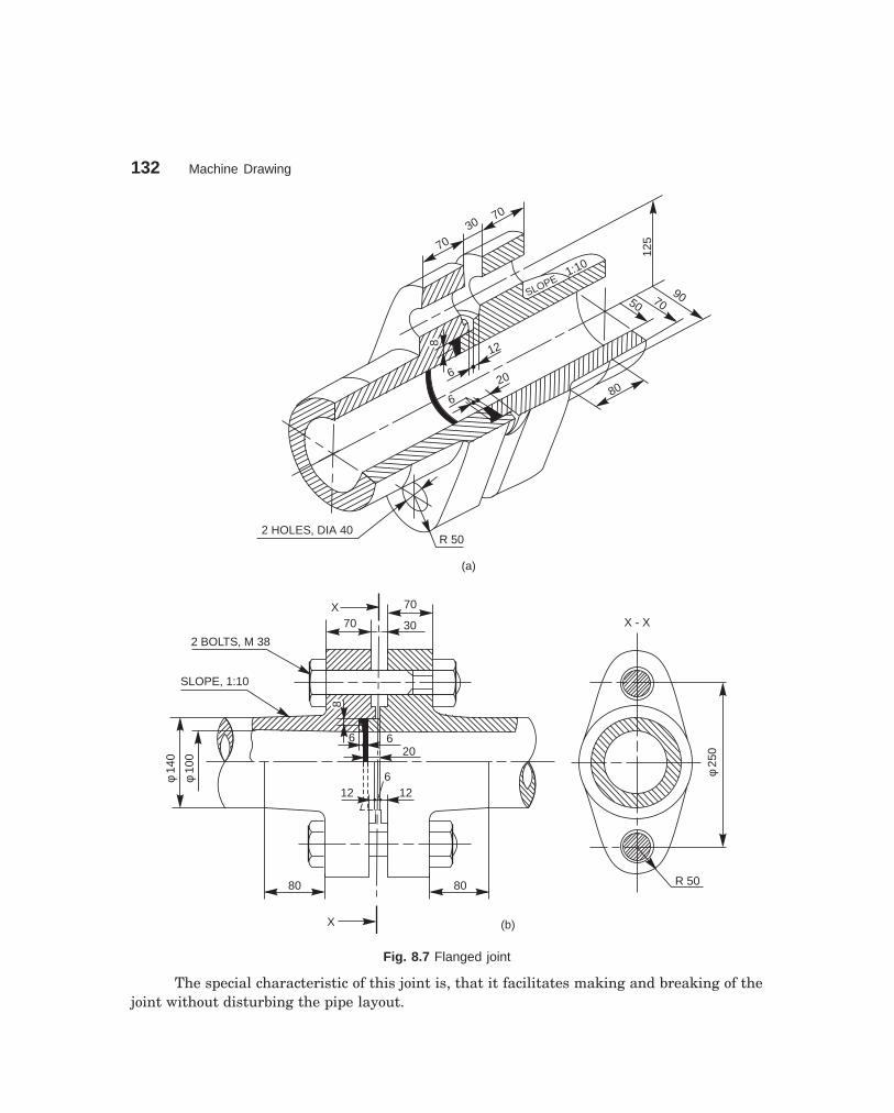
132 Machine Drawing
dharmd:\N-Design\Des8-1.pm5 Seventh Print
SLOPE1:10
70
7030
88
6
12
2 HOLES, DIA 40R 50
(a)
6
2080
907050
125
X 70
3070
X
88
6 620
12 126f
100
f14
0
80 80
2 BOLTS, M 38
SLOPE, 1:10
(b)
f25
0
R 50
X - X
Fig. 8.7 Flanged joint
The special characteristic of this joint is, that it facilitates making and breaking of thejoint without disturbing the pipe layout.

Pipe Joints 133
dharmd:\N-Design\Des8-1.pm5 Seventh Print
119 825
35 80 35
10
C
BA
f70
f50
f90 M
100
M10
0
f13
0
M70
M70 f90
f90
f96
f96
f92
f92
65138
f50
f70 f
80 f85
Fig. 8.8 Union joint
�+����,�������������
Long pipes, carrying steam and other hot fluids may undergo axial expansion and contractiondue to variations of the fluid temperature. Expansion joints are used to accommodate suchexpansions or contractions.
Corrugated copper fitting (Fig. 8.9a) or a loop made of copper pipe (Fig. 8.9b) may beplaced between two pipes at suitable intervals, to act as an expansion joint.
(a)
D
R
R
45° 45°
DR
(b)
Fig. 8.9 (a)–Corrugated fitting, (b)–Loop
For better results, an expansion joint, a gland with stuffing box is used. In this, thesleeve B can have free axial motion in the stuffing box A. The pipes to be joined are connectedto the sleeve B and stuffing box A, at their ends, through flanged joints.
Leakage through the joint is prevented by the asbestos packing D, stuffed in the boxand compressed by the gland C, as the nuts E are tightened. The flanges of the sleeve and thestuffing box are connected by bolts F. When the pipes experience expansion or contraction,either the sleeve or the stuffing box or both move axially. The nuts used with the bolts F, maybe adjusted to permit the axial movement (Fig. 8.10).
When an expansion joint is used in a pipe line, it is advisable that the pipes are notrigidly clamped but are suspended on hangers or supported on rollers (Fig. 8.11).

134 Machine Drawing
dharmd:\N-Design\Des8-1.pm5 Seventh Print
30 30
D
A CE
B
F
X
X
400
f30
0f
450
f30
0
f25
0
30 60
320
f12
0
f23
0
18
18
120
30 f12
0
f15
6f
192
f25
0f
360
X–X
75
Fig. 8.10 Gland and stuffing box expansion joint
(a) (b)
Fig. 8.11 Pipe supports (a)–Hanger, (b)–Roller
�-� ����� ������.
Pipe fittings, such as bends, elbows, tees, crosses, etc., are used with wrought iron and steelpipes of relatively smaller sizes, so that they are either connected or branched-off at rightangle. The following are some of the commonly used pipe fittings:
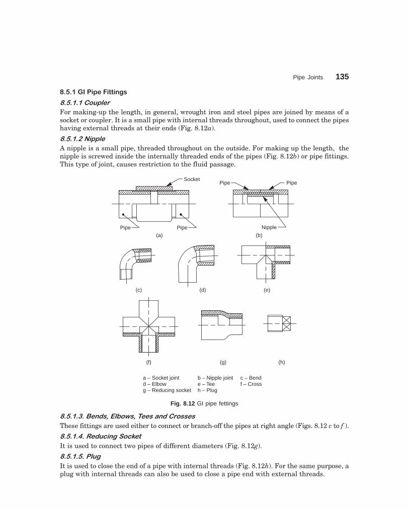
Pipe Joints 135
dharmd:\N-Design\Des8-1.pm5 Seventh Print
�-���.�������������"�
�������������
For making-up the length, in general, wrought iron and steel pipes are joined by means of asocket or coupler. It is a small pipe with internal threads throughout, used to connect the pipeshaving external threads at their ends (Fig. 8.12a).
������ ����
A nipple is a small pipe, threaded throughout on the outside. For making up the length, thenipple is screwed inside the internally threaded ends of the pipes (Fig. 8.12b) or pipe fittings.This type of joint, causes restriction to the fluid passage.
SocketPipe
Nipple
(b)(a)Pipe Pipe
(c) (d) (e)
(f) (g) (h)
a – Socket jointd – Elbowg – Reducing socket
b – Nipple jointe – Teeh – Plug
c – Bendf – Cross
Pipe
Fig. 8.12 GI pipe fettings
�������������� ���������������������
These fittings are used either to connect or branch-off the pipes at right angle (Figs. 8.12 c to f ).
����������������������
It is used to connect two pipes of different diameters (Fig. 8.12g).
������������
It is used to close the end of a pipe with internal threads (Fig. 8.12h). For the same purpose, aplug with internal threads can also be used to close a pipe end with external threads.

136 Machine Drawing
dharmd:\N-Design\Des8-1.pm5 Seventh Print
�-�����������������"�
For small size cast iron and steel pipes upto 2.5 inches size and less, the fittings are threaded.Cast iron pipe fittings of greater diameter are provided with flanges (Fig. 8.13).
(a) (b) (c) (d) (e)
45°
(g) (h) (i) (j)(f)
(a) 90° Elbow (b) 90° long radius elbow (c) 45° Elbow (d) Side outlet 90° Elbow
(e) Tee (f) Cross (g) Side outlet tee (h) 45° Lateral (i) Reducer (j) Tee reducer
Fig. 8.13 CI pipe fittings
�-�� �/����������$�������"�
Plastic pipes and pipe fittings made of polyvinyle chloride (PVC) are extensively used foragricultural, industrial and domestic use. These pipes are made in sizes varying from 20 mmto 315 mm diameter as per IS 4985:81.
f32
f25
f25
18 18
40
a-Coupling 25 × 25
f25
f20
f32
18 15
40
4
b-Reducer 25 × 20
6
f25
f20
f32
25
40
c-Female threadadapter 25 × 20
Fig. 8.14 PVC pipe fittings (contd.)

Pipe Joints 137
dharmd:\N-Design\Des8-1.pm5 Seventh Print
19 6
f25
f25
f18
f32
22
40
d-Male threadadapter 25 × 25
f32
f25
19
19
50
f 25
f 32
e-Elbow 25 × 25
1818
1832
f 25
f 32
f32
f25
f25
64
32
f-Tee 25
1818
15
f 20
f 32
f32
f25
f25
64
32
g-Tee female threadadapter 25 × 25 × 20
16Fig. 8.14 PVC pipe fittings
�����������������������
PVC pipes exhibit the following salient features:1. Smoother bore in comparison to CI, GI and also cement pipes, thereby better flow
characteristics.2. Seemless, strong and resilient.3. Light weight, offering total economy in handling, transportation and installation.4. Resistance to chemical, electrolytic and galvanic corrosion.5. Odourless and hygienic for transporting potable water, as they do not subject to
contamination.6. Maintenance free.7. Long-lasting-PVC is free from weakening by scale formation, rusting, weathering
and chemical action and hence more durable for rated working conditions.������ �!��"������
The following properties are expected from pipes made as per BIS specifications:1. Thermal conductivity – 4 × 10⁻⁴ cal/hr – cm/°C/cm2
2. Co-efficient of linear expansion – 5.0 to 6.0 × 10⁻⁵ mm/°C3. Specific gravity – 1.41 gms/cm3
4. Combined flexural and compressive strength – 600 kg/cm2
5. Impact strength at 20°C–3 kg/cm2

138 Machine Drawing
dharmd:\N-Design\Des8-1.pm5 Seventh Print
6. Electrical resistance – 1014 ohms cm7. Modulus of elasticity – approximately 30,000 kg/cm2
8. Vicat softening point – 81°C.Dimensions of PVC pipes as per IS 4985-1981 are given in Table 8.1. It may be noted
that the pipe size indicates the outside diameter of the pipe. However, the sizes of the fittingsindicate the inside diameter. The dimensions of commonly used PVC pipe fittings are shown inFig. 8.14, for 25 mm pipe.
The description of the fittings and their technical data are given in Table 8.2.
Table 8.1 Dimensions of PVC pipes All dimensions in millimetres
Wall thickness for working pressures
Outside Tolerance Class 1 Class 2 Class 3 Class 4diameter on outside 2.5 kgf/cm2 4 kgf/cm2 6 kgf/cm2 10 kgf/cm2
diameter Min. Max. Min. Max. Min. Max. Min. Max.
20 + 0.3 — — — — — — 1.1 1.525 + 0.3 — — — — — — 1.4 1.832 + 0.3 — — — — — — 1.8 2.240 + 0.3 — — — — 1.4 1.8 2.2 2.750 + 0.3 — — — — 1.7 2.1 2.8 3.363 + 0.3 — — 1.5 1.9 2.2 2.7 3.5 4.175 + 0.3 — — 1.8 2.2 2.6 3.1 4.2 4.990 + 0.3 1.3 1.7 2.1 2.6 3.1 3.7 5.0 5.7
110 + 0.4 1.6 2.0 2.5 3.0 3.7 4.3 6.1 7.0140 + 0.5 2.0 2.4 3.1 3.8 4.8 5.5 7.7 8.7160 + 0.5 2.3 2.8 3.7 4.3 5.4 6.2 8.8 9.9180 + 0.6 2.6 3.1 4.2 4.9 6.1 7.0 9.9 11.1200 + 0.6 2.9 3.4 4.6 5.3 6.8 7.7 11.0 12.3225 + 0.7 3.3 3.9 5.2 6.0 7.6 8.6 12.4 13.9250 + 0.8 3.6 4.2 5.7 6.5 8.5 9.6 13.8 15.4280 + 0.9 4.1 4.8 6.4 7.3 9.5 10.7 15.4 17.2315 + 1.0 4.6 5.3 7.2 8.2 10.7 12.0 17.3 19.3
Table 8.2 PVC pipe fittings—technical data (contd.)
Description size in mm Inch ApplicationsI.D equivalent
1. Coupler 20 0.50 These are used for joining two25 0.75 PVC pipes.32 1.0040 1.2550 1.5063 2.00
2. 90° Elbow 20 to 110 0.5 to 4.0 These are used for short turns of 90°.
3. 90° Bend 20 to 315 0.5 to 12.00 These are used where long turns ofangle are required. They do not causeany losses due to friction.

Pipe Joints 139
dharmd:\N-Design\Des8-1.pm5 Seventh Print
Table 8.2 PVC pipe fittings—technical data
Description size in mm Inch ApplicationsI.D equivalent
4. Equal tee 20 to 160 0.5 to 6.0 These are used for bypass and takingbig service line out of main line.
5. Reducer tee 20 to 160 0.5 to 6.0 These are used for reduced tappingfrom main line
6. Male threaded 20 to 140 0.5 to 5.00 These are used to connect the GI pipeadapter (MTA) line/metal line and all types of valves,
taps, etc., through a male portion ofPVC threaded adaptors.
7. Female threaded 20 to 90 0.5 to 3.0 These are used to connect a PVC pipeadapter (FTA) line directly to a metal pipe.
8. Reducing FTA 25 × 20 0.75 × 0.5 These are used to connect a PVCto to pipeline directly to a metal pipe of
90 × 75 3.0 × 2.50 lower diameter or vice-versa.
9. Reducer 25 × 20 0.75 × 0.5 These are used to convert the serviceto to line, into a small line.
160 × 140 6.0 × 5.0
���������#""��������
The following are the typical applications of PVC pipes:1. Agricultural and lift irrigation2. Rural and urban drinking water supply3. Industrial/chemical effluent disposal4. Acids and slurries transportation5. Telecommunication cable ducting6. Bio-gas (Gober-gas)/Natural gas, and oil distribution lines7. Tube well casings8. Under-ground or open pipe line/drainage9. Domestic plumbing and drainage
10. Sewage and drainage11. Air conditioning/industrial ducting12. Main line in sprinkler/drip irrigation
��������$����
Threaded PVC pipe fittings should not be over-tightened, as the threads may get damaged.PVC pipes should never be threaded, and they are joined by a solvent cement or by suitablethreaded fittings. The steps followed for joining the PVC pipes are:
1. The pipes are cut as square as possible. The pipe and socket should be clean and dry.The surface is cleaned with emery paper before joining.
2. Thick coat of solvent cement is applied on the outer surface of the pipe and also on theinner surface of the socket.
3. The pipe is inserted into the socket and turned through 90° for even distribution ofcement.

140 Machine Drawing
dharmd:\N-Design\Des8-1.pm5 Seventh Print
4. The joint is held firmly without slipping for 2 minutes and allowed to dry.5. After 24 hours, the pipe lines are ready for use.
�0� ����� (�'���
Pipe layout is a kind of drawing, that shows how the various pipes are fitted together, to make-up a piping system. It shows the location, size and orientation of the pipe fittings and valves.As the components of a system are standard ones, it is sufficient to show simplifiedrepresentation of the components.
Figure 8.15 shows the layouts of cast iron and GI pipe line, incorporating most of thepipe fittings.
Gate valve Cap
Lateral
CrossGlobe valve
Elbow Plug Union
Elbow
Tee FlangedJoint
CheckValve
TransitionPiece
45° Elbow
(a) CI pipe layout
Tap
Coupling
Pipe
Reducer elbow
Pipe
Flanges
Tee
Cross
Elbow
Full wayValve
Pipe nippleUnion
Half way valve
Plug
Cock valve
Bend
(b) GI pipe layout
Fig. 8.15 Pipe layout

Pipe Joints 141
dharmd:\N-Design\Des8-1.pm5 Seventh Print
THEORY QUESTIONS
8.1 What is the criteria for selecting the pipe material?8.2 How are pipe joints classified?8.3 What are the methods of strengthening a cast iron steam pipe joint so as to withstand higher
pressures?8.4 Differentiate between the joints for CI pipes and joints for copper pipes.8.5 What is the purpose of providing a packing of compressible material, between the flanges in a
flanged pipe joint?8.6 Explain how the flanges are provided at the ends of the steam pipes, used for joining wrought
iron and steel pipes.8.7 Name the different types of joints used for hydraulic pipes.8.8 Where and why a socket and spigot pipe joint is used?8.9 What is the special feature of a union joint?
8.10 What is the purpose of providing an expansion joint in the pipe line, carrying hot fluids?8.11 Explain the working of an expansion joint.8.12 Describe any three types of pipe fitting, used in the pipe layout, made of (a) Gl, (b) CI and (c) PVC
pipes.
DRAWING EXERCISES
8.1 Sketch the conventional representation of pipe threads.8.2 Draw (a) sectional view from the front and (b) view from the side of different forms of flanged
joints used for cast iron steam pipes of diameter 100 mm.8.3 Sketch any one method of strengthening cast iron steam pipe joints so that it will withstand
higher pressures.8.4 Indicating proportions, sketch any one method of joining (a) copper steam pipes and (b) wrought
iron or steel pipes of diameter 100 mm.8.5 Sketch a suitable pipe joint to connect two pipes, each of diameter 250 mm. The pipes are to be
laid underground. Indicate proportionate dimensions of various parts of the joint.8.6 Draw (a) sectional view from the front and (b) view from the side of a hydraulic pipe joint of
flanged type, to connect two pipes, each of diameter 50 mm.8.7 Sketch a union joint and mark the proportions on it, by choosing suitable value for the pipe size.8.8 Draw (a) sectional view from the front and (b) view from the side of a gland and stuffing box type
of expansion joint, to connect two pipes, each of diameter 100 mm.8.9 Sketch any three types of (a) GI, (b) CI and (c) PVC pipe fittings, indicating proportions.
8.10 Sketch (a) CI and (b) GI pipe layouts, incorporating most of the fittings.

142
9�������
�� �� �������
Power transmission between shafts is achieved either through gear or belt drives. In the lattercase, pulleys are mounted on shafts, over which a belt runs, transmitting the power. Generally,pulleys are made of cast iron or wrought iron; but at times, from steel plates also, by weldedconstruction. Depending upon the application, a pulley may be of a single piece or split type.The latter one is used, where a pulley has to be mounted at an intermediate location on a shaft.Pulleys are mounted on shafts, by using sunk keys.
��� ����� � ���� �������
Flat and V-belts are used for power transmission between shafts. A flat belt operates on apulley with a smooth surface; whereas pulleys with wedge shaped groove(s) is (are) used withV-belt(s).
���� �����������������
These pulleys are of different sizes and shapes, the designs of which are based on the functionalrequirements. A flat belt drive uses a flat belt of rectangular cross-section; the width of whichis appreciably larger than the thickness. The belt operates on the surface of a pulley. Thefollowing are the main types of pulleys used with flat belts:
��������������� �
The main parts of a pulley are the hub or boss, rim and arms or spokes. Figure 9.1 shows anarmed pulley with the proportions marked. It may be noted that the arms of a pulley are eitherstraight or curved; the cross section being elliptical in shape.
Rims of cast iron pulleys are often provided with slight convexity, known as crowning.This prevents the axial slipping of the belt during operation.
����������� �����������
When the diameter of a pulley is relatively small, the hub and rim of the pulley are connectedwith a web, which is in the form of a disc. Figure 9.2 shows a pulley with a web. To make thepulley light in weight, holes may be provided in the web.
��������������� ��
Step cone pulleys are mounted on both the driver and driven shafts in opposite directions toprovide different speed ratios between them for a constant speed of the driver shaft. Thediameters of the steps in the two pulleys are such that the same belt can operate on any pair ofsteps. These pulleys are used in machine tools, such as lathe, drilling machine, etc. Figure 9.3shows a step cone pulley with four steps.

Pulleys 143
dharmd:\N-Design\Des9-1.pm5 Seventh Print
12
65
4050
132
138 14
5
f 36
18
(a)
X
X
KEYWAY, 8 4´
f 36
20 20
X
X
18
12
f26
4
f10
0
f80
f27
6
f29
0
65X - X
Fig. 9.1 Pulley with arms
Flat belts are used when the centre distance between the two shafts is more. However,V-belts are preferred when the shafts are located closer. The V-belt drive is relatively slip free.It is used for transmission ratios upto and above 15:1 without tension pulleys. The contactarea between the belt and pulley can be increased and thus the power transmission can also beenhanced.

144 Machine Drawing
dharmd:\N-Design\Des9-1.pm5 Seventh Print
35X - X
5 15
f90
f80
f 20f 40
KEYWAY, 6 3´
X
X
Fig. 9.2 Pulley with web
KEYWAY,6 3´
4040
5555 70
85
30120
8
810160
4040
40
f 30
(a)
R55
R70
f80
40 40 40 40
f60
f17
0
(b)
f 30
KEYWAY, 6 3´
Fig. 9.3 Step cone pulley for flat belt drive

Pulleys 145
dharmd:\N-Design\Des9-1.pm5 Seventh Print
������������������������ ��
When a number of machines are operated from a single power source, each machine is providedwith a fast and loose pulley arrangement. With this arrangement, any machine may be startedor stopped at will, while the lay shaft is running continuously.
Figure 9.4 shows the arrangement of a fast and loose pulley. In this, the fast pulley ismounted on the shaft with a keyed joint, whereas the loose pulley runs freely on the shaft. Thediameter of the loose pulley is slightly less than that of the fast pulley so that when the belt isshifted on to the loose pulley, its tension is reduced. Power is transmitted only when the belt ison the fast pulley. Loose pulley takes care of the idling time of the machine and does nottransmit any power.
24
11036
12
110
R21
5
116 116
f96
f64 f
45f
45
f84
f84
M 12
50
KEY,14 9´
24
36
R 10 R 12
Fig. 9.4 Fast and loose pulleys
����������������������
When a V-belt is used for power transmission, the pulley rim is modifide by providing wedgeshaped groove(s) so that the V-belt(s) can run in the groove(s).
Figure 9.5 (a) shows a V-belt pulley that operates with a single V-belt and Fig. 9.5 (b),pulley with three V-belts. In multiple V-belt drive; even if one belt fails, the ramaining beltscontinue the drive until it is convenient to shut down the machine for repairs. This drive, onaccount of wedging effect of the belt in the groove, causes less pull on the shaft than flat belt ofthe same general characteristics.

146 Machine Drawing
dharmd:\N-Design\Des9-1.pm5 Seventh Print
������������������� ��� ���!"� ��
The principle and the purpose for which a step cone pulley for V-belt drive is used are the sameas those associated with the step cone pulley for flat belt. Figure 9.6 shows a cone pulley forV-belt with four steps.
f 25f 25
f 80
40° SET SCREW,M 8
5 5 2020
5 45°´
f40
10
f50
(a)
KEYWAY, 6 3´
(b)
4 HOLES, DIA 36 ON PCD 125
5 5
70
f25
f50
22
f36
18 25
f25
0
51040°
78
Fig. 9.5 V-belt pulleys

Pulleys 147
dharmd:\N-Design\Des9-1.pm5 Seventh Print
2016
1616
16
53
55
553
13.5
1616
16
55
55
3×
45°
115
45
(a)
KEYWAY,
6 × 3
3 × 45° 6557.55047.542.5
22.5 27
.5 3542
.5 52.5
f 25f 45
45
f95
f13
0
8 816 16 16 16
5 5 5
f45
f10
0
f11
5
115
(b)
KEYWAY, 6 × 3
f 85
f 25
Fig. 9.6 Step cone pulley for V-belt drive
����! "#��������
A rope drive is used for transmission of power over large distances. Ropes of cotton, manilla orhemp, fitting into circumferential grooves on the pulleys are used for power transmission. Thedrive may use either a single or multiple ropes.
A rope pulley is similar to V-belt pulley in construction, except for slight changes in thegrooves as shown Fig. 9.7. This drive is preferred for transmission of power between shaftslocated at different elevations and at varying distances. Steel ropes are used for higher powertransmission and in cases such as winch drives, rope ways, overhead cranes, etc.

148 Machine Drawing
dharmd:\N-Design\Des9-1.pm5 Seventh Print
60
X
X
f170 25
15
f26
0
X–X
8 25 25 8
10
R35 5
70ROPE, DIA 20
f70
f60
f30
10
45°
Fig. 9.7 Rope pulley
THEORY QUESTIONS
9.1 What is the use of a pulley?9.2 How are pulleys mounted on shafts?9.3 Name different types of pulleys?9.4 What is “crowning” and where and why it is applied?9.5 When is a flat belt pulley recommended?9.6 What are the various types of flat belt pulleys?9.7 What is the difference between an armed pulley and a pulley with a web?9.8 What is meant by fast and loose pulleys? Explain its working principle.9.9 What is the difference between a flat belt and a V-belt?
9.10 What are the various types of V-belt pulleys?9.11 Where and why a step cone pulley is used?9.12 Where do you recommend a rope drive?9.13 Differentiate between a V-belt drive and a rope drive.9.14 What are the materials used for the ropes?
DRAWING EXERCISES
9.1 Sketch the following types of flat belt pulleys, providing necessary views; with proportionatedimensions marked:

Pulleys 149
dharmd:\N-Design\Des9-1.pm5 Seventh Print
(a) armed pulley,(b) pulley with a web.,The pulleys are to be mounted on a shaft of diameter 50mm.
9.2 Sketch the necessary view of a step cone pulley with four steps, operating with (a) flat belts and(b) V-belts.Assume that the pulleys are to be mounted on shafts of diameter 50 mm.
9.3 Sketch (a) sectional view from the front and (b) view from the side of a fast and loose pulleys.Assume that the unit is to be mounted on a shaft of diameter 50 mm.
9.4 Giving proportionate dimensions; sketch the necessary views of a V-belt pulley that operateswith three V-belts.
9.5 Sketch (a) sectional view from the front and (b) view from the side of a rope pulley. The pulley isto be mounted on a shaft of diameter 50 mm.

150
10������������
� �� ��������
Riveted joints are permanent fastenings and riveting is one of the commonly used method ofproducing rigid and permanent joints. Manufacture of boilers, storage tanks, etc., involve joiningof steel sheets, by means of riveted joints. These joints are also used to fasten rolled steelsections in structural works, such as bridge and roof trusses.
� �� ������� ��� �������
� ����������
A rivet is a round rod of circular cross-section. It consists of two parts, viz., head and shank(Fig. 10.1 (a)). Mild steel, wrought iron, copper and aluminium alloys are some of the metalscommonly used for rivets. The choice of a particular metal will depend upon the place ofapplication.
� �������������
Riveting is the process of forming a riveted joint. For this, a rivet is first placed in the holedrilled through the two parts to be joined. Then the shank end is made into a rivet head byapplying pressure, when it is either in cold or hot condition.
Shank
Head
(a)
1.6 d
0.7d
dd
0.97 d0.97 d
tt 2.
25d
0.95 d
Clearancebeforeriveting
(b)
Fig. 10.1 (a) Rivet (b) Riveting
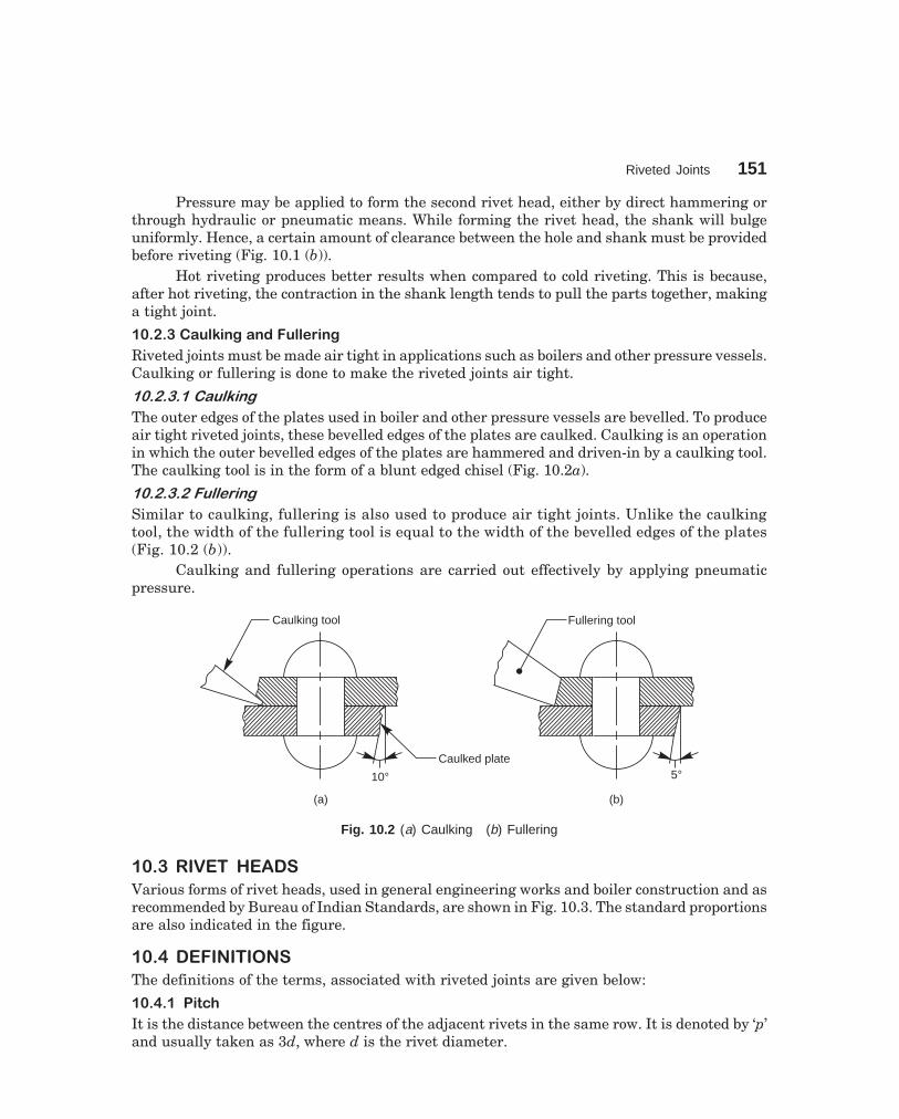
Riveted Joints 151
dharmd:\N-Design\Des10-1.pm5
Pressure may be applied to form the second rivet head, either by direct hammering orthrough hydraulic or pneumatic means. While forming the rivet head, the shank will bulgeuniformly. Hence, a certain amount of clearance between the hole and shank must be providedbefore riveting (Fig. 10.1 (b)).
Hot riveting produces better results when compared to cold riveting. This is because,after hot riveting, the contraction in the shank length tends to pull the parts together, makinga tight joint.
� ������������������ ����!���
Riveted joints must be made air tight in applications such as boilers and other pressure vessels.Caulking or fullering is done to make the riveted joints air tight.
������������� �
The outer edges of the plates used in boiler and other pressure vessels are bevelled. To produceair tight riveted joints, these bevelled edges of the plates are caulked. Caulking is an operationin which the outer bevelled edges of the plates are hammered and driven-in by a caulking tool.The caulking tool is in the form of a blunt edged chisel (Fig. 10.2a).
������������� �
Similar to caulking, fullering is also used to produce air tight joints. Unlike the caulkingtool, the width of the fullering tool is equal to the width of the bevelled edges of the plates(Fig. 10.2 (b)).
Caulking and fullering operations are carried out effectively by applying pneumaticpressure.
Caulking tool
Caulked plate
10°
(a)
5°
(b)
Fullering tool
Fig. 10.2 (a) Caulking (b) Fullering
� �� ������ "����
Various forms of rivet heads, used in general engineering works and boiler construction and asrecommended by Bureau of Indian Standards, are shown in Fig. 10.3. The standard proportionsare also indicated in the figure.
� �# �� �����
The definitions of the terms, associated with riveted joints are given below:
� �#����$��%&
It is the distance between the centres of the adjacent rivets in the same row. It is denoted by ‘p’and usually taken as 3d, where d is the rivet diameter.

152 Machine Drawing
dharmd:\N-Design\Des10-1.pm5
dd
0.7
d 1.6 d
Snap head0.
7d 2 d
R = 1.7 D
0.6
d
1.76 d
R = 3.5 d
R
High buttonhead
Pan head Cone head
0.7
d 1.6 d
d
0.2
d
0.25
d1.5 d
0.25
d
1.5 d
Flat head Truss head
0.25
d
2 d
0.25
d
2 d
Flush counter-sunk head
Round topcountersunk head
dd dd dd
dd dd dd dd
Fig. 10.3 Types of rivet heads
� �#����'�!���
It is the distance from the edge of the plate to the centre of the nearest rivet. It is usually takenas 1.5d, where d is the rivet diameter. It is denoted by ‘m’.
� �#�����&������������
If the rivets are used along a number of rows such that the rivets in the adjacent rows areplaced directly opposite to each other, it is known as chain riveting (Fig. 10.10).
� �#�#��(��)(�����������
In a multi-row riveting, if the rivets in the adjacent rows are staggered and are placed in-between those of the previous row, it is known as zig-zag riveting (Fig. 10.11).
� �#�*���+,�$��%&
It is the distance between two adjacent rows of rivets. It is denoted by ‘pr’ and is given by,pr = 0.8p, for chain riveting pr = 0.6p, for zig-zag riveting.
� �#�-������+����$��%&
This term is usually associated with zig-zag riveting and is denoted by ‘pd’. It is the distancebetween the centre of a rivet in a row to the next rivet in the adjacent row.
� �* �.���� ������ � �������� ����
Riveted joints may be broadly classified into : structural joints and pressure vessel joints.
� �*������!�%��!����+���/
Structural steel frames are made by using rolled steel plates and sections of standard shapes,as shown in Fig. 10.4.
Figure 10.5 shows an angle joint used to connect two plates at right angle. Here, an(equal) angle is used to connect the plates, by a single row of rivets. Figure 10.5 also shows theposition of the rivets and other proportions of the joint.
Figure 10.6 shows rolled steel sections, i.e., a column and a beam connected to eachother through riveted joints. Figure 10.7 illustrates one design of a built-up girder, also madeof rolled steel sections. In both the figures, proportions of the joints are also indicated.

Riveted Joints 153
dharmd:\N-Design\Des10-1.pm5
90°
91.5
°
96°
91°
Fig. 10.4 Structural rolled steel sections
3 dt 1.5 d 1.5 d
1.5
d1.
5d
t
d
Fig. 10.5 Angle joint
40
1010
150
d
15037
.5
37.575
8
8
75
80
10
10 10
20
Fig. 10.6 Column and beam

154 Machine Drawing
dharmd:\N-Design\Des10-1.pm5
10 10 p75
X X–
1010
45 75
225105
30 30
400
X X
Fig. 10.7 Built-up girder
However, it should be noted that the length of the joint is decided by the load to beresisted by the joint.
�������� ���� ����������� ������ ��� �
This is one kind of butt joint made either with a single or double strap. As the name implies,the rivets in this joint are arranged in a diamond shape. Figure 10.8 shows a double strapdiamond butt joint. The joint is generally used to connect tie bars in bridge structures and rooftrusses.
� �*����0+���!��+���/
These joints are used mainly for joining metal sheets used in the construction of boilers, watertanks and pressure vessels. Obviously, these joints must be made air-tight, as the above vesselsare required to retain fluids and withstand internal fluid pressure as well.
For manufacturing boilers, water tanks and pressure vessels, the edges of the plates tobe joined (in case of lap joints only) are first bevelled. The plates are then rolled to the requiredcurvature of the shell. Holding the plates together, holes are then drilled and riveting is followed.
Boiler joints are classified as: lap joints, butt joints and combination of lap and buttjoints.
���������������� ��
In a lap joint, the plates to be riveted, overlap each other. The plates to be joined are firstbevelled at the edges, to an angle of about 80° (Fig. 10.9). Depending upon the number of rows

Riveted Joints 155
dharmd:\N-Design\Des10-1.pm5
of rivets used in the joint, lap joints are further classified as single riveted lap joint, doubleriveted lap joint and so on.
dd
t 2t 2
t
1.5 d 1.5 d 1.5 d 1.5 d
X X–
X X
1.5
D1.
5D
pr pr pr pr pr pr
pp
Fig. 10.8 Double strap diamond butt joint
t
10°
t
1.5 d 1.5 d
X X–
dd
10°
X X
p
Fig. 10.9 Single riveted lap joint
In multi-row riveted joints, rows may be arranged either in chain or zig-zag fashion(refer articles 10.4.3 and 10.4.4 for explanation), as shown in Figs. 10.10 and 10.11.

156 Machine Drawing
dharmd:\N-Design\Des10-1.pm5
Figure 10.9 shows a single riveted lap joint. The size of the rivet, d is taken as,
d = 6 t mm where ‘t’ is the thickness of the plates to be joined in millimetres.Figures 10.10 and 10.11 show double riveted chain, lap joint and double riveted zig-zag
lap joint respectively.
t
t1.5d 1.5d
dd
X X–
X X
p
pr
Fig. 10.10 Double riveted chain lap joint
dd
t
t1.5d 1.5d
X – X
X Xpr
pd p
0.5
P0.
5P
Fig. 10.11 Double riveted zig-zag lap joint
����������������� ��
In a butt joint, the plates to be joined, butt against each other, with a cover plate or strap,either on one or both sides of the plates; the latter one being preferred. In this joint, the buttingedges of the plates to be joined are square and the outer edges of the cover plate(s) is(are)bevelled.
These joints are generally used for joining thick plates, and are much stronger than lapjoints. Figures 10.12 and 10.13 show single riveted single strap and a single riveted doublestrap, butt joints respectively.

Riveted Joints 157
dharmd:\N-Design\Des10-1.pm5
In a single strap butt joint, the thickness of the strap (cover plate) is given by, t1 = 1.125tIf two straps are used, the thickness of each cover plate is given by, t2 = 0.75t
1.5d 1.5d
1.5 d 1.5 d
d
tt 1
X – X
XX
p
Fig. 10.12 Single riveted, single strap butt joint
1.5 d 1.5 d 1.5 d 1.5 d
d
X – X
t 2t 2
t
XX
p
Fig. 10.13 Single riveted, double strap butt joint

158 Machine Drawing
dharmd:\N-Design\Des10-1.pm5
1.5d 1.5d 1.5d 1.5d
X – X
d
t 2t 2
t
XX
p
pr pr
Fig. 10.14 Double riveted, double strap chain butt joint
Figures 10.14 and 10.15 show double riveted, double strap chain, butt joint and doubleriveted, double strap zig-zag butt joint.

Riveted Joints 159
dharmd:\N-Design\Des10-1.pm5
1.5d 1.5d 1.5d 1.5d
X – X
d
t 2t 2
t
XXpr
p
0.5
p0.
5p
pr
Fig. 10.15 Double riveted, double strap zig-zag butt joint
THEORY QUESTIONS
10.1 Name the commonly used materials for rivets.10.2 Define the following :
(a) pitch, (b) row pitch, (c) diagonal pitch and (d) margin.10.3 How are riveted joints made air-tight?10.4 Name the different types of rivet heads as recommended by BIS : SP-46 : 1988.10.5 What is a structural joint?

160 Machine Drawing
dharmd:\N-Design\Des10-1.pm5
10.6 How are boiler joints classified?10.7 Differentiate between :
(a) lap joint and butt joint, (b) chain riveting and zig-zag riveting10.8 What is the function of a cover plate in riveted joints?
DRAWING EXERCISES
10.1 Giving proportionate dimensions, sketch any four forms of commonly used rivet heads, choosingthe rivet diameter as 10 mm.
10.2 Sketch any two types of structural riveted joints, indicating proportionate dimensions.10.3 Draw (a) sectional view from the front and (b) view from above, of the following riveted joints, to
join plates of thickness 10 mm:(i) single riveted lap joint, (ii) double riveted chain lap joint, (iii) double riveted zig-zag lap joint,(iv) single riveted, single strap butt joint, (v) single riveted, double strap butt joint (vi) doubleriveted, double strap, chain butt joint and (vii) double riveted, double strap, zig-zag butt joint.
10.4 Through sketches, illustrate the caulking and fullering operations.

161
11�����������
�� � ��������
Welding is an effective method of making permanent joints between two or more metal parts.Cast iron, steel and its alloys, brass and copper are the metals that may be welded easily.Production of leak proof joints that can withstand high pressures and temperatures are madepossible with advanced welding technology. For this reason, welding is fast replacing castingand forging wherever possible. When compared to riveting, welding is cheaper, stronger andsimpler to execute at site with considerable freedom in design. Hence, it is widely used in shipbuilding and structural fabrication in place of riveting.
�� � ������� ����� ��� �������
Basic terms of a welded joint are shown in Fig. 11.1 and the five basic types of joints are shownin Fig. 11.2.
Root openingBasemetal
Weldface
Roo
tfa
ce
Fusionzone
(a)
Bevel angle
Groove or includedangle
Wel
dsi
ze
Toe
Toe
Fusion zone
Weld face
Weld size, legT
hick
ness
Throat
Root
(b)
Fig. 11.1 (a) Butt weld (b) Fillet weld
Various categories of welded joints (welds) are characterized by symbols which, in generalare similar to the shape of welds to be made. These symbols are categorised as:

162 Machine Drawing
dharmd:\N-Design\Des11-1.pm5
(i) Elementary symbols (Table 11.1),(ii) Supplementary symbols (Table 11.2),
(iii) Combination of elementary and supplementary symbols (Table 11.3) and(iv) Combination of elementary symbols (Table 11.4).
Corner joint
Edge joint
Tee joint Butt joint
Lap joint
Fig. 11.2 Types of joints
�� � ������������� �������� ��!"#������������$%&��'�
The complete method of representation of the welds on the drawing comprises, in addition tothe symbol (3), the following (Fig. 11.3):
2b3
300a 5
4
2a
1
Joint
Fig. 11.3
(i) An arrow line (1) per joint,
(ii) A dual reference line, consisting of two parallel lines; one continuous and one dashed(2a, 2b) and
(iii) A certain number of dimensions (4) and conventional signs (3).
NOTE The dashed line may be drawn either above or below the continuous line (Fig. 11.8). Forsymmetrical welds, the dashed line is omitted.
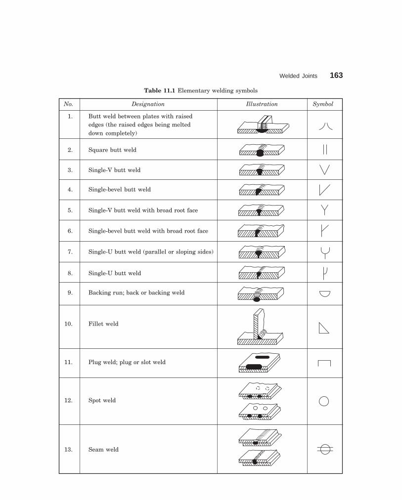
Welded Joints 163
dharmd:\N-Design\Des11-1.pm5
Table 11.1 Elementary welding symbols
No. Designation Illustration Symbol
1. Butt weld between plates with raisededges (the raised edges being melteddown completely)
2. Square butt weld
3. Single-V butt weld
4. Single-bevel butt weld
5. Single-V butt weld with broad root face
6. Single-bevel butt weld with broad root face
7. Single-U butt weld (parallel or sloping sides)
8. Single-U butt weld
9. Backing run; back or backing weld
10. Fillet weld
11. Plug weld; plug or slot weld
12. Spot weld
13. Seam weld

164 Machine Drawing
dharmd:\N-Design\Des11-1.pm5
Table 11.2 Supplementary welding symbols
Shape of weld surface Symbol
(a) Flat (usually finished flush)
(b) Convex
(c) Concave
Table 11.3 Combination of elementary and supplementary symbols
Designation Illustration Symbol
Flat (flush) single-V butt weld
Convex double-V butt weld
Concave fillet weld
Flat (flush) single-V butt weld with flat
(flush) backing run
Table 11.4 Combination of elementary symbols (contd.)
No. Designation Representation Symbolization
symbol either or(For number
refer to IllustrationTable 11.1)
1. Squarebutt weld
2
welded fromboth sides
2–2
2.Single-Vbutt weld
3

Welded Joints 165
dharmd:\N-Design\Des11-1.pm5
No. Designation Representation Symbolization
symbol either or(For number
refer to IllustrationTable 11.1)
3. andbacking run
9
3–9
4. Double-Vbutt weld
3
(X weld)3–3
5. Doublebevel
butt weld
4
6. (K weld)4–4
7. Double-Ubutt weld
7
7–7
8. Fillet weld
10
and filletweld
9 10
10–10
Table 11.4 Combination of elementary symbols
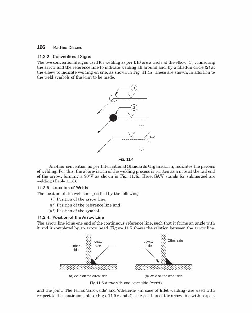
166 Machine Drawing
dharmd:\N-Design\Des11-1.pm5
�� � � �����(������%����'��
The two conventional signs used for welding as per BIS are a circle at the elbow (1), connectingthe arrow and the reference line to indicate welding all around and, by a filled-in circle (2) atthe elbow to indicate welding on site, as shown in Fig. 11.4a. These are shown, in addition tothe weld symbols of the joint to be made.
1
2
(a)
(b)
SAW
Fig. 11.4
Another convention as per International Standards Organisation, indicates the processof welding. For this, the abbreviation of the welding process is written as a note at the tail endof the arrow, forming a 90°V as shown in Fig. 11.4b. Here, SAW stands for submerged arcwelding (Table 11.6).
�� � ) ����*%������� ���� �
The location of the welds is specified by the following:(i) Position of the arrow line,
(ii) Position of the reference line and(iii) Position of the symbol.
�� � + �������������������$$�&�����
The arrow line joins one end of the continuous reference line, such that it forms an angle withit and is completed by an arrow head. Figure 11.5 shows the relation between the arrow line
ArrowsideOther
side
(a) Weld on the arrow side
Arrowside
Other side
(b) Weld on the other side
Fig.11.5 Arrow side and other side (contd.)
and the joint. The terms ‘arrowside’ and ‘otherside’ (in case of fillet welding) are used withrespect to the continuous plate (Figs. 11.5 c and d). The position of the arrow line with respect

Welded Joints 167
dharmd:\N-Design\Des11-1.pm5
to the weld is generally of no special significance (Fig. 11.6). However, in the case of edgepreparation (Refer No. 4, 6 and 8 in Table 11.1), the arrow line points towards the plate whichis prepared (Fig. 11.7).
Arrow sideof jointA
Other sideof joint A
Joint A
Joint B
Arrow sideof joint B
Other sideof joint B
Arrow sideof joint B
Join
tB
Join
tA
Other sideof joint B
Other sideof joint A
Arrow sideof joint A
(c) (d)
Fig. 11.5 Arrow side and other side
Fig. 11.6 Position of arrow lines Fig. 11.7 Indication of edge preparation
�� � , ������������� ���������$��*������
The reference line shall preferably be drawn parallel to bottom edge of the drawing and if it isnot possible; then it is drawn perpendicular.
�� � - �������������������!"#��
The symbol is placed either above or beneath the reference line as per the following regu-lation:
It is placed on the continuous side of the reference line, if the weld (weld face) is on thearrow side of the joint or on the dashed line side, if the weld is on the other side of the joint, asshown in Fig. 11.8.

168 Machine Drawing
dharmd:\N-Design\Des11-1.pm5
a 5 300 z 7 300
a z
z = a 2
s l s l
(a) For symmetrical welds only
(c) To be welded on the other side
(b) To be welded on the arrow side
Fig. 11.8 Position of the symbol
�� )� ��������.��/������
Each weld symbol may be accompanied by acertain number of dimensions. These dimensionsare written as indicated in Fig. 11.9. It shows (i)the main dimensions relative to the cross-section,written on the left hand side of (before) thesymbol and (ii) longitudinal dimension writtenon the right hand side of (after) the symbol.
NOTE The absence of any indication fol-lowing the symbol, signifies that the weld is tobe continuous over the whole length of the workpiece.
�� ) ����"��������'�/��������� �
There are two methods to indicate the dimensionsof fillet welds as shown in Fig. 11.10. The lettera (throat thickness), or z (leg length) is alwaysplaced in front of the value of the correspondingdimension.
����� ����� ����� �� �� �����
The contours of edge preparation for butt welds are shown in Fig. 11.11.The method of indicating the main dimensions and the rules for setting down these
dimensions are illustrated in Table 11.5.
Fig. 11.9. Dimensioning of welds
Fig. 11.10 Dimensioning-fillet welds

Welded Joints 169
dharmd:\N-Design\Des11-1.pm5
M
G
1.5 to 3
Upt
o6
60°
0to
31.5 to 53 to 6
T < 10T > 10
T>
12 0to 3
60°
3 to 6T0
to 3
45° to 50°
T < 10T > 10
3 to 55 to 8
5 to 8
>12
0to
1.5
45° to 50
>12 10 to 5
0 to 3
1.5
to5
10 to 20°
0 to 3
10 to 20°
>25 10 to 5
1.5
to3
10 to 20°
r = 10 to 5
>12
r
0 to 3
1.5
to3
>25
r = 10 to 5
10 to 20°
1.5
to3
0 to 3
Fig. 11.11 Edge preparation
�� ,� ���/���� /���0
Finishing of welds other than cleaning, shall be indicatedby suitable contour and finish symbols, viz., chipping C,machining M and grinding G. Where a weld is required tohave approximately flush surface without any othermethod of finishing, a straight line should be added belowthe symbol to indicate it (Fig. 11.12).
����� ����� � � ��� ������� ������ �������� ���� ��
1. Symbols for fillet and similar welds should be shown, such that the vertical portion ofthe symbols are indicated on the left hand side of the symbol, irrespective of theorientation of the weld metal.
2. If the welds are to be made on the arrow side of a joint, the corresponding symbol shouldbe placed either above or below the cotinuous reference line (Fig. 11.8).
3. If the welds are to be made on the other side of a joint, the corresponding symbol shouldbe placed above or below the dashed reference line (Fig. 11.8).
4. If the welds are to the made on both sides of a joint, the corresponding symbols shouldbe placed on both sides of the reference line and the dashed line is not shown (Fig. 11.8).
Fig. 11.12
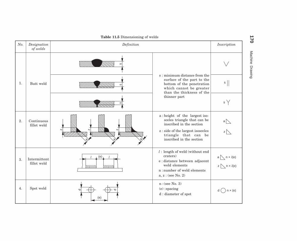
170M
achine Draw
ing
dharmd:\N
-Design\D
es11-1.pm5
Table 11.5 Dimensioning of welds
No. Designationof welds
Definition Inscription
1. Butt weld
s : minimum distance from thesurface of the part to thebottom of the penetrationwhich cannot be greaterthan the thickness of thethinner part
2. Continuousfillet weld
a : height of the largest iso-sceles triangle that can beinscribed in the section
z : side of the largest isoscelestriangle that can beinscribed in the section
3. Intermittentfillet weld
l : length of weld (without endcraters)
e : distance between adjacentweld elements
n : number of weld elementsa, z : (see No. 2)
4. Spot weldn : (see No. 3)(e) :spacingd : diameter of spot
s
s
a
z
a n × (e)l
z n × (e)l
d n × (e)
ss
s
l l(e)
d d
(e)
z
a
z
a
z
a
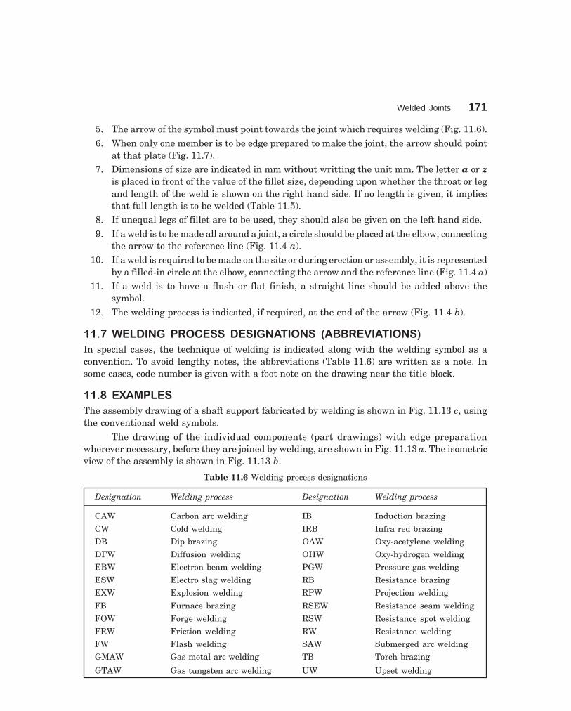
Welded Joints 171
dharmd:\N-Design\Des11-1.pm5
5. The arrow of the symbol must point towards the joint which requires welding (Fig. 11.6).6. When only one member is to be edge prepared to make the joint, the arrow should point
at that plate (Fig. 11.7).7. Dimensions of size are indicated in mm without writting the unit mm. The letter a or z
is placed in front of the value of the fillet size, depending upon whether the throat or legand length of the weld is shown on the right hand side. If no length is given, it impliesthat full length is to be welded (Table 11.5).
8. If unequal legs of fillet are to be used, they should also be given on the left hand side.9. If a weld is to be made all around a joint, a circle should be placed at the elbow, connecting
the arrow to the reference line (Fig. 11.4 a).10. If a weld is required to be made on the site or during erection or assembly, it is represented
by a filled-in circle at the elbow, connecting the arrow and the reference line (Fig. 11.4 a)11. If a weld is to have a flush or flat finish, a straight line should be added above the
symbol.12. The welding process is indicated, if required, at the end of the arrow (Fig. 11.4 b).
����� �������� � ����� �������� ��� �������� ���
In special cases, the technique of welding is indicated along with the welding symbol as aconvention. To avoid lengthy notes, the abbreviations (Table 11.6) are written as a note. Insome cases, code number is given with a foot note on the drawing near the title block.
�� 1� �2������
The assembly drawing of a shaft support fabricated by welding is shown in Fig. 11.13 c, usingthe conventional weld symbols.
The drawing of the individual components (part drawings) with edge preparationwherever necessary, before they are joined by welding, are shown in Fig. 11.13 a. The isometricview of the assembly is shown in Fig. 11.13 b.
Table 11.6 Welding process designations
Designation Welding process Designation Welding process
CAW Carbon arc welding IB Induction brazing
CW Cold welding IRB Infra red brazing
DB Dip brazing OAW Oxy-acetylene welding
DFW Diffusion welding OHW Oxy-hydrogen welding
EBW Electron beam welding PGW Pressure gas welding
ESW Electro slag welding RB Resistance brazing
EXW Explosion welding RPW Projection welding
FB Furnace brazing RSEW Resistance seam welding
FOW Forge welding RSW Resistance spot welding
FRW Friction welding RW Resistance welding
FW Flash welding SAW Submerged arc welding
GMAW Gas metal arc welding TB Torch brazing
GTAW Gas tungsten arc welding UW Upset welding

172 Machine Drawing
dharmd:\N-Design\Des11-1.pm5
(a)
R 20
1260
110
12
X
60
75
1 2
f 30
12
3
4
12
45°
3
10
R 12 15°
3R 10
2:1
Detail at X
(b)
Fig. 11.13 Shaft support (contd.)
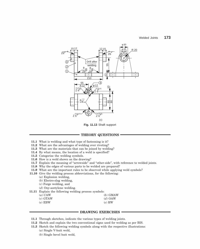
Welded Joints 173
dharmd:\N-Design\Des11-1.pm5
110
Drill afterwelding
8Z6
8Z6
15 12 12 15
Z6 Z6
3
2
1
5512
R 20
f 30
f 20
455R 12
Z 6 Z 6
f 12
Z 6Z 6
6
1060 80
(c)
Fig. 11.13 Shaft support
THEORY QUESTIONS
11.1 What is welding and what type of fastesning is it?11.2 What are the advantages of welding over riveting?11.3 What are the materials that can be joined by welding?11.4 By what means, the location of a weld is specified?11.5 Categorise the welding symbols.11.6 How is a weld shown on the drawing?11.7 Explain the meaning of ‘‘arrowside’’ and ‘‘other-side’’, with reference to welded joints.11.8 Why the edges of various parts to be welded are prepared?11.9 What are the important rules to be observed while applying weld symbols?
11.10 Give the welding process abbreviations, for the following:(a) Explosion welding,(b) Electro-slag welding,(c) Forge welding, and(d) Oxy-acetylene welding.
11.11 Explain the following welding process symbols:(a) CAW (b) GMAW(c) GTAW (d) OAW(e) EBW (e) RW
DRAWING EXERCISES
11.1 Through sketches, indicate the various types of welding joints.11.2 Sketch and explain the two conventional signs used for welding as per BIS.11.3 Sketch the following welding symbols along with the respective illustrations:
(a) Single V-butt weld,(b) Single bevel butt weld,

174 Machine Drawing
dharmd:\N-Design\Des11-1.pm5
(c) Single U-butt weld,(d) Single J-butt weld,(e) Fillet weld, and(f) Convex double V-butt weld.
11.4 Explain the meaning of each weld shown in Figs. 11.14 to 11.17 and sketch the part drawings.
Fig. 11.14 Fig. 11.15
f30
20
8 65R 10
2 HOLES,DIA 10
R1090°
R 22
f 20
R 10
75
Fig. 11.16 Fig. 11.17
11.5 Suggest suitable welding joints to fabricate the swing bracket shown in Fig. 11.18.11.6 Indicate appropriate welded joints shown by symbols to fabricate the structural joints shown in
Figs. 11.19 and 11.20.
4040
25 6
2 HOLES, DIA 16R20
61250
74
3210
f 16
f 25
115
50 20
R 20
20
E
D
CA
B E
F
G
Fig. 11.18 Fig. 11.19

Welded Joints 175
dharmd:\N-Design\Des11-1.pm5
B
45°
48
24M 20
2
14218
6
A
12
24
18
9
30C
132
162
3
3
82
13884
12
3 HOLES,DIA 18
35°
D
138
54
36
242424
1
Fig. 11.20

Journal
176
12��������
� ���� ����� �
Bearings are supports for shafts, providing stability, and free and smooth rotation. Theimportance of bearings may be understood from the supporting requirement of machine toolspindles, engine crankshafts, transmission or line shafts in workshops, etc. Bearings are broadlyclassified into two categories: sliding contact bearings and rolling contact bearings or anti-friction bearings.
� �������� � ������ ��������
Sliding contact bearings are those in which the rotating shaft has a sliding contact with thebearing and the friction is relatively high. Hence, these bearings require more lubrication.According to the direction in which the bearing is loaded, these bearings are further classifiedas: journal bearings and thrust bearings.
�������������������
When the load on a bearing is perpendicular (normal)to the shaft axis, the bearing is known as a journalbearing. In fact, the term ‘journal’, refers to that partof the shaft which is in contact with the bearing(Fig.12.1). The following are some of the types ofjournal bearings:
������������������� �������� �
This is the simplest among the journal bearings, and usually made of cast iron. This consists ofa cylindrical block with a rectangular base. The hole in the cylindrical block supports the shaftand the holes in the base are used for bolting down the bearing. A hole provided at the top ofthe body is used for introducing lubricant into the bearing (Fig. 12.2). The drawback of thisbearing is the absence of provision for adjustment in case of wear and hence it has to be discorded.Hence, this is used when the load on the bearing is small and the wear is immaterial.
������������������� �������� �
This bearing consists of mainly two parts, the body and the bush. The body is usually made ofcast iron and the bush of soft materials such as brass, bronze or gunmetal. The bush is pressfitted in the body; preventing relative axial and rotary motion. With this arrangement, torenew the bearing, it is only necessary to renew the bush. The oil hole provided at the top ofthe body and running through the bush is used to introduce the lubricant (Fig. 12.3).
Fig. 12.1 Journal bearing-representation

Bearings 177
dharmd:\N-Design\Des12-1.pm5
20
20
85
35
30
15f 25
R 25
OIL HOLE, DIA 1.5 CSK AT 90°
TO DIA 3R 25 f 25
85 20 15
30
f 15
35
OIL HOLE, DIA 1.5 CSK
AT 90° TO DIA 3
� 15
Fig. 12.2 Solid journal bearing
56
35
2 HOLES,12 × 8
6 40
1620
15
12
12
R 25
R 16
20
50f 25
R 25
f 32
16 168083
1535
12
8
20
4050
OIL HOLE, DIA 3.5CSK AT 45° TO DIA 5
OIL HOLE, DIA 3.5CSK AT 45° TO DIA 5
f25
33
Fig. 12.3 Bushed journal bearing
����������������������� �����������������
This bearing is used for long shafts, requiring intermediate support, especially when the shaftcannot be introduced in the bearing end-wise. It consists of a pedastal or base, a cap and abush, split into two halves, called ‘bearing brasses’. The split parts used in the assembly, facilitateeasy assembly and periodical replacement of the worn-out brasses.
After placing the journal on the lower half of the bush, kept in the base, the upper halfof the bush is placed and the cap is then fixed to the pedastal, by means of two bolts (Fig. 12.4).Flanges are provided at either end of the bush, to prevent its axial motion. The rotary motionof the bush is prevented by a snug provided at the bottom of the lower brass, fitting into acorresponding hole in the base.

178 Machine Drawing
dharmd:\N-Design\Des12-1.pm5
28
1213
0f16
Bolt
OIL HOLE,DIA 3, DEEP 20,CSK DIA 6
144
Cap
f19620
64
3022
88
6363
103636
1212
f63
f50
Block
16
22
2
105
130
Brasses
SNUG, DIA 6
LONG 10
R38
R 72105R 58
64
5
12
1622
44 64
32
10
R 72
10
OIL HOLE, DIA 3DEEP 20CSK DIA 6
105
R 58
3
3636
206
f16
f19 99
28
30 21212
210
610
25
f50
R33
R 38
25
22
6325
2
Fig. 12.4 Plummer block

Bearings 179
dharmd:\N-Design\Des12-1.pm5
Instead of a snug, the brasses may be provided with square or octogonal seatings toprevent relative movement. The polygonal shaped seatings provided adjacent to the flages, fitinto the corresponding recesses in the base and the cap. The seatings used are narrow in widthto reduce the amount of machining (Fig. 12.5).
10
1232
10
f 6
33� 40
f 3f 3
f 30f 30
f25
f25
1012
32 12
10
f 6
33� 50
f 3f 3
f 30f 30
f25
f25
f 60f 60
f76
f68
f76
f68 f
50
R30
12
OIL HOLE, DIA 3
8
8
62
SNUG, DIA 6LONG 10
12
f 50f 50
SNUG, DIA 6LONG 10
OIL HOLE, DIA 3
Fig. 12.5 Brasses
������������������� ��� ��������� ��
Brackets and hangers with bearings mounted, are used to support transmission or line shafts.However, in some cases, a part of the bearing housing may be cast integral with the bracket orhanger.
������ �!�������
Bracket bearing supports a shaft running parallel to and near a wall or near a row of pillars.The vertical plate of the bracket is bolted to the wall or pillar; the number of bolts used dependsupon the size and shape of the bracket.
"����!����� �
In the case of a wall bracket, the size of the bracket depends upon the biggest size of the pulleythat is to be mounted on the shaft. Fig. 12.6 shows a wall bracket with a pedastal bearing mountedon it. It may be noted from the figure, that the pedastal is integrally cast with the bracket.

180 Machine Drawing
dharmd:\N-Design\Des12-1.pm5
45
35
2525
4040
2828
2020
f36
f25 R
18R
18
2 BOLTS, M6
1036
2
R25
7050
9
15
3
212 23
3
2
312
R130
6
5
2512
025
140
3
12f 9f 9
Fig. 12.6 Wall bracket with a pedastal bearing
128
4
22
R 9
2525
88
3030
34
f 9
R 15R 15
R20
R20
f 20f 20
15
STUD, M 8
30
1012
2 22
102
30
R75
4
22 8 2
160
70
10
6
15 2
18
R25
Fig. 12.7 Pillar bracket with a pedestal bearing
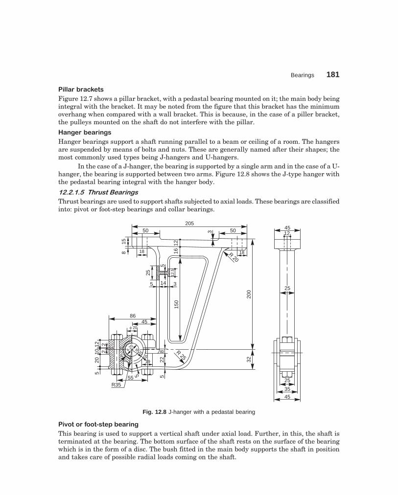
Bearings 181
dharmd:\N-Design\Des12-1.pm5
#������!����� �
Figure 12.7 shows a pillar bracket, with a pedastal bearing mounted on it; the main body beingintegral with the bracket. It may be noted from the figure that this bracket has the minimumoverhang when compared with a wall bracket. This is because, in the case of a piller bracket,the pulleys mounted on the shaft do not interfere with the pillar.
$������!�������
Hanger bearings support a shaft running parallel to a beam or ceiling of a room. The hangersare suspended by means of bolts and nuts. These are generally named after their shapes; themost commonly used types being J-hangers and U-hangers.
In the case of a J-hanger, the bearing is supported by a single arm and in the case of a U-hanger, the bearing is supported between two arms. Figure 12.8 shows the J-type hanger withthe pedastal bearing integral with the hanger body.
���������������������� ��
Thrust bearings are used to support shafts subjected to axial loads. These bearings are classifiedinto: pivot or foot-step bearings and collar bearings.
20550 503
R20
18161215
8 1820
03220
1012
52
2
5
55 522
44f
25f
25R 20
195
8 R25
f 20
8645
150
12.5
5
25
5 14 3
45
35
25
4512
2525
R35
Fig. 12.8 J-hanger with a pedastal bearing
#�%� ����&�� '� �(�!������
This bearing is used to support a vertical shaft under axial load. Further, in this, the shaft isterminated at the bearing. The bottom surface of the shaft rests on the surface of the bearingwhich is in the form of a disc. The bush fitted in the main body supports the shaft in positionand takes care of possible radial loads coming on the shaft.

182 Machine Drawing
dharmd:\N-Design\Des12-1.pm5
f 115
f 95
Bush
SNUG, WIDE 10 R 40
R30
R30R 40
R15
012
1810
33
44
1212
1616
1616
45451212
1616
22
12
33
120
19
80
DiscPIN, DIA 5,
LONG 12
120
20
30
Block
80
38 222 75
16
SNUG,WIDE 10
f 80
1018
75
44
f 60
f 80
3
R150
16 16
1645
12
2
32
2
201717
1924240
3
PIN, DIA 5, LONG 12
22
16
3838
160
R 57.5
Fig. 12.9 Foot-step bearing

Bearings 183
dharmd:\N-Design\Des12-1.pm5
The disc is prevented from rotation by a pin inserted through the body and away fromthe centre. The bush is also prevented from rotation by a snug, provided at its neck, below thecollar (Fig. 12.9). The space between the shaft and the collar, serves as an oil cup for lubricatingthe bearing. The bush and the body are recessed to reduce the amount of machining. The baseof the body is also recessed to serve the same purpose.
������� )��� �!������
This is generally used for supporting a horizontal shaft under axial load. Further, in this, theshaft extends through and beyond the bearing. The shaft in a collar thrust bearing may consistsof one or more collars which are either fitted to or integral with the shaft (Fig. 12.10). Thecollars rotate against the stationary split bearing surfaces.
(a) (b)
Solid bearingSplit bearing
Collar Oil hole Collars
Fig. 12.10 (a) Single collar bearing, (b) Multi-collar bearing
�* � ������ � ������ +����',���� �-� ��������
The bearings, in which a rolling friction is present, are known as rolling contact bearings. Asrolling friction is very much less than sliding friction, rolling contact bearings are called anti-friction bearings.
The bearing consists of four parts: inner race, outer race, balls or rollers and a cage orretainer (Fig. 12.11). The inner race is fitted tight into the stationary housing. Figure 12.12shows the mounting of a shaft with a ball bearing. The arrangement also illustrates the methodused to prevent the axial movement of the bearing.

184 Machine Drawing
dharmd:\N-Design\Des12-1.pm5
Outer race
Inner race
Balls
Cage
Fig. 12.11 Parts of a ball bearing
Locking washer
Fig. 12.12 Mounting of a radial ball bearing
Anti-friction bearings are further classified into: radial bearings and thrust bearings.
�*�����.������������
Radial bearings are used to resist normal (radial) loads acting on the shafts. These bearingsare sub-divided on the basis of the shape of the rolling elements used, viz., ball bearings, rollerbearings and taper roller bearings.
Figure 12.13 shows various types of anti-friction bearings, mounted on a common shaft.From the figure, it may be seen that a single row radial bearing is shown in three differentsizes or series, viz., light, medium and heavy. The selection of a particular size depends uponthe magnitude of the load acting on the bearing. Sometimes, double row ball bearings are usedinstead of single row ball bearings, to resist heavy loads.
Manufacturer's use a numbering system to denote the type of series (sizes) of the bearings.For example 2xx, 3xx, 4xx series correspond to light, medium and heavy series respectively.The last two digits when multiplied by 5, gives the bore or shaft size in millimetres. Thus 308bearing signifies medium series bearing of 40mm bore. Additional digits if present, may referto manufacturer's details.

Bearings 185
dharmd:\N-Design\Des12-1.pm5
Ligh
tser
ies
Med
ium
serie
s
Hea
vyse
ries
Single row ball bearing
Dou
ble
row
ball
bear
ing
Ang
ular
cont
act
ball
bear
ing
Cyl
indr
ical
rolle
rbe
arin
g
Tape
rro
ller
bear
ing
Nee
dle
bear
ing
Thr
ust b
all b
earin
g
Fig. 12.13 Types of anti-friction bearings
Figure 12.14 illustrates the application of a self-aligning double row ball bearing in aplummer block. Students are advised to refer manufacturer's catalogues to know the varioustypes and sizes, including their load carrying capacities.
11575
15 1577 4 4
18
1818
f75
f75
f60
f12
22 R 57 R 50
f 25
M 12
f70
3
6 15 48
f84
f88
f 150
f96
f 60
9
26 24
12
96275
9 33 33
175
148
M12
503
150
755
209
f 21
Fig. 12.14 Plummer block with double row self-aligning ball bearing
�*���)��� ���������
These bearings are used to support shafts subjected to axial loads. In general,balls asrolling elements are used in these bearings and rollers only in special cases.
Figure 12.15 shows the mounting of a shaft with a thrust ball bearing.Figure 12.16 illustrates a foot-step bearing with a thrust ball bearing to resist axial
loads and a radial ball bearing to position the vertical shaft and also to resist the possibleradial loads.
Figure 12.17 shows the application of taper roller bearing, thrust ball bearing and adouble row ball bearing in a revolving centre.

186 Machine Drawing
dharmd:\N-Design\Des12-1.pm5
Fig. 12.15 Mounting of a thrust ball bearing
1060
1018
88
103
1410
f 80
f 60
18
f 40
f 60
f 70
f 45
20
220
3
3
15°
2510
015
150
26 8 8152
R 8
R 8
6 HOLES, DIA 6
f 63
f 120
f 98f 74
15
Fig. 12.16 Foot-step bearing with radial and thrust ball bearings

Bearings 187
dharmd:\N-Design\Des12-1.pm5
15 22
M52
f58
15 15
f16
8 10 15 30 15 10300
335
30 28
2
f60
60°
25 42
2 2 2 2
f38
f64 f
85
f35
f42f
62M
100
f11
8
f12
4
f45
Fig. 12.17 Revolving center
THEORY QUESTIONS
12.1 What is a bearing and what is meant by journal?12.2 How are bearings classified?12.3 Name the different forms of journal bearings.12.4 Under what conditions, a pedastal bearing is preferred?12.5 Name the various parts of a plummer block.12.6 How the bolts are prevented from rotation in a plummer block?12.7 What are the commonly used bearing materials?12.8 Why collars are provided at the sides of bearings brasses?12.9 What is a snug? What is the function of it in the bearing?
12.10 Why countersunk hole is provided at the top of the body of the bearing?12.11 Why elongated holes are generally provided in the base of a bearing?12.12 Why is the base of the bearing generally kept hollow at the bottom?12.13 Why a disc is provided at the shaft end in a pivot bearing?12.14 Distinguish between:
(a) sliding contact bearings and anti-friction bearings,(b) bracket and hanger bearings,(c) pivot bearing and collar bearing, and(d) journal bearing and thrust bearing.
12.15 What is a rolling contact bearing?12.16 Why are rolling contact bearings called anti-friction bearings?12.17 What are the different shapes of the rolling elements used in anti-friction bearings?12.18 Explain the specification of a bearing 205.
DRAWING EXERCISES
12.1 Draw (a) half sectional view from the front, with left half in section and (b) view from above of abushed bearing, suitable for supporting a shaft of diameter 25mm.

188 Machine Drawing
dharmd:\N-Design\Des12-1.pm5
12.2 Draw the following views of a plummer block, suitable for supporting a shaft of diameter 50mm:
(a) half sectional view from the front, with left half in section,
(b) sectional view from the side, and
(c) view from above.
12.3 Sketch any two designs used to prevent rotational movement of the bearing brasses.
12.4 Sketch the necessary views of a foot-step bearing, for supporting a shaft of diameter 50mm. Giveall important proportionate dimensions.
12.5 Indicating proportionate dimensions, sketch the necessary views of the following types of bear-ings:
(a) wall bracket with a pedastal bearing,
(b) pillar bracket with a pedastal bearing, and
(c) J-hanger with a pedastal bearing.
12.6 Sketch a ball bearing and indicate the various parts of it.
12.7 Illustrate through sketches, the mountings of (a) radial ball bearing and (b) thrust ball bearing.
12.8 Sketch the sectional views of the following:
(a) single row ball bearing, (b) cylindrical roller bearing,
(c) taper roller bearing and (d) thrust ball bearing.
12.9 Draw (a) view from the front and (b) sectional view from the side of a plummer block with doublerow self-aligning ball bearing, suitable for supporting a shaft of diameter 30mm.
12.10 Draw (a) sectional view from the front and (b) view from above of a foot-step bearing with radialand thrust ball bearings, suitable for supporting a shaft of diameter 60mm.
12.11 Indicating proportionate dimensions, sketch half sectional view from the front of a revolvingcentre, using thrust ball bearing, taper roller bearing and a double row ball bearing.
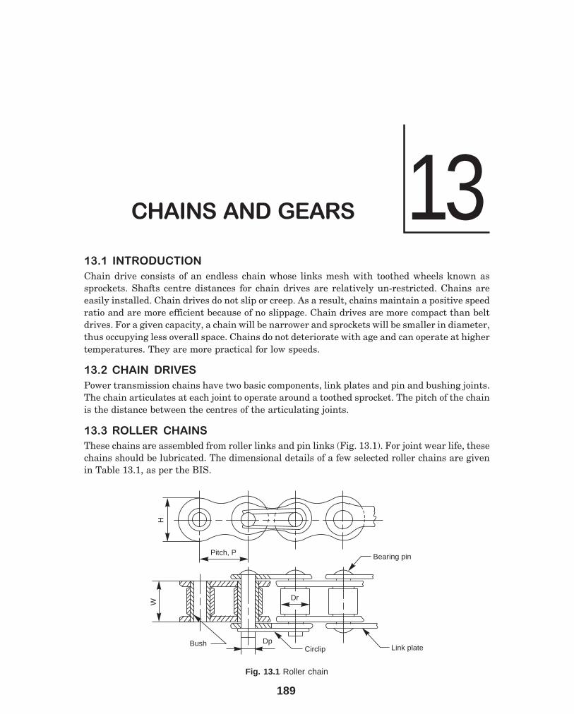
189
13��������������
� �� ������������
Chain drive consists of an endless chain whose links mesh with toothed wheels known assprockets. Shafts centre distances for chain drives are relatively un-restricted. Chains areeasily installed. Chain drives do not slip or creep. As a result, chains maintain a positive speedratio and are more efficient because of no slippage. Chain drives are more compact than beltdrives. For a given capacity, a chain will be narrower and sprockets will be smaller in diameter,thus occupying less overall space. Chains do not deteriorate with age and can operate at highertemperatures. They are more practical for low speeds.
� �� ������ �����
Power transmission chains have two basic components, link plates and pin and bushing joints.The chain articulates at each joint to operate around a toothed sprocket. The pitch of the chainis the distance between the centres of the articulating joints.
� � ������ ������
These chains are assembled from roller links and pin links (Fig. 13.1). For joint wear life, thesechains should be lubricated. The dimensional details of a few selected roller chains are givenin Table 13.1, as per the BIS.
Pitch, P
H
Bush
W
DpCirclip Link plate
Bearing pin
DrDr
Fig. 13.1 Roller chain
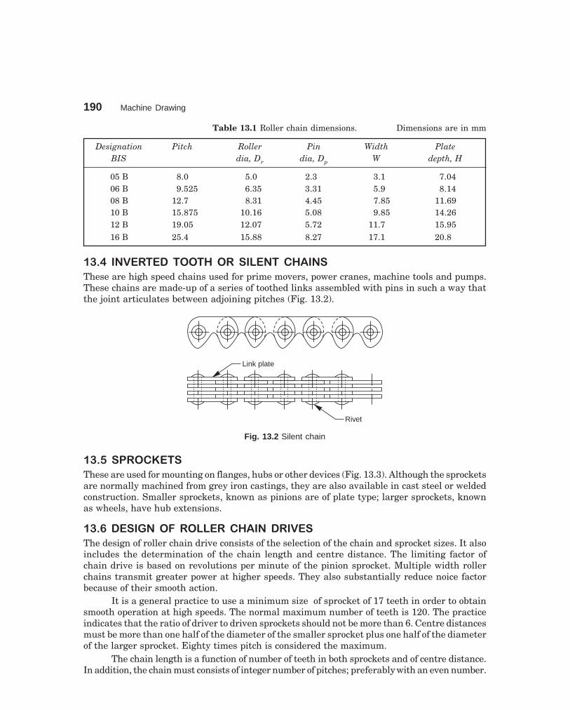
190 Machine Drawing
dharmd:\N-Design\Des13-1.pm5
Table 13.1 Roller chain dimensions. Dimensions are in mm
Designation Pitch Roller Pin Width PlateBIS dia, Dr dia, Dp W depth, H
05 B 8.0 5.0 2.3 3.1 7.0406 B 9.525 6.35 3.31 5.9 8.1408 B 12.7 8.31 4.45 7.85 11.6910 B 15.875 10.16 5.08 9.85 14.2612 B 19.05 12.07 5.72 11.7 15.9516 B 25.4 15.88 8.27 17.1 20.8
� �� ������� ��������� ������ ������
These are high speed chains used for prime movers, power cranes, machine tools and pumps.These chains are made-up of a series of toothed links assembled with pins in such a way thatthe joint articulates between adjoining pitches (Fig. 13.2).
Link plate
Rivet
Fig. 13.2 Silent chain
� �� ��������
These are used for mounting on flanges, hubs or other devices (Fig. 13.3). Although the sprocketsare normally machined from grey iron castings, they are also available in cast steel or weldedconstruction. Smaller sprockets, known as pinions are of plate type; larger sprockets, knownas wheels, have hub extensions.
� �� �������� �����������������
The design of roller chain drive consists of the selection of the chain and sprocket sizes. It alsoincludes the determination of the chain length and centre distance. The limiting factor ofchain drive is based on revolutions per minute of the pinion sprocket. Multiple width rollerchains transmit greater power at higher speeds. They also substantially reduce noice factorbecause of their smooth action.
It is a general practice to use a minimum size of sprocket of 17 teeth in order to obtainsmooth operation at high speeds. The normal maximum number of teeth is 120. The practiceindicates that the ratio of driver to driven sprockets should not be more than 6. Centre distancesmust be more than one half of the diameter of the smaller sprocket plus one half of the diameterof the larger sprocket. Eighty times pitch is considered the maximum.
The chain length is a function of number of teeth in both sprockets and of centre distance.In addition, the chain must consists of integer number of pitches; preferably with an even number.
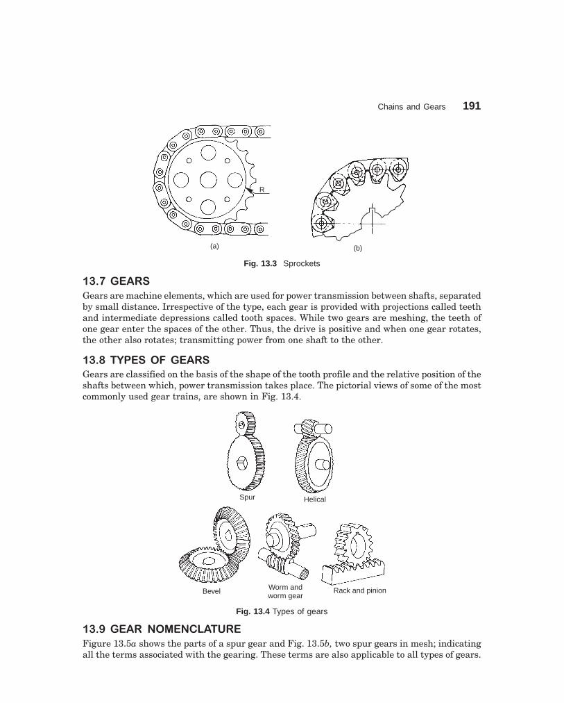
Chains and Gears 191
dharmd:\N-Design\Des13-1.pm5
R
(b)(a)
Fig. 13.3 Sprockets
� �� ���
Gears are machine elements, which are used for power transmission between shafts, separatedby small distance. Irrespective of the type, each gear is provided with projections called teethand intermediate depressions called tooth spaces. While two gears are meshing, the teeth ofone gear enter the spaces of the other. Thus, the drive is positive and when one gear rotates,the other also rotates; transmitting power from one shaft to the other.
� �� �������� ���
Gears are classified on the basis of the shape of the tooth profile and the relative position of theshafts between which, power transmission takes place. The pictorial views of some of the mostcommonly used gear trains, are shown in Fig. 13.4.
Spur Helical
Bevel Worm andworm gear
Rack and pinion
Fig. 13.4 Types of gears
� �� ��� ����������
Figure 13.5a shows the parts of a spur gear and Fig. 13.5b, two spur gears in mesh; indicatingall the terms associated with the gearing. These terms are also applicable to all types of gears.

192 Machine Drawing
dharmd:\N-Design\Des13-1.pm5
� �� � ������ �������
A number of curves may be used for the tooth profile. However, from a commercial stand point,cycloidal and involute curves are used. Of these two, involute form is extensively used becauseof its advantages from manufacturing and operational points of view.
� �� �����!"#$%&'��##&(��)#*+$'
Involute is a curve traced by a point on a straight line when it rolls without slipping, on thecircumference of a circle. Figure 13.6 shows the stages in drawing the involute tooth of a gear.The following are the steps involved in the construction.
Fillet
Face
width(B)
Root
Thickness
Circular pitch
Pitch circle
(a)
Dedendum
Whole depth Common tangent
Addendum
Centre distance
(b)
Pitch point
Line ofaction
Clearance
Base
circle
dia(D
)b
Pressureangle, ( )f
Add
endu
mci
rcle
dia
(D)
a
Pitch circle dia (D)
Dedendumcircle
dia (D)d
Face
Flank
Fig.13.5 Gear nomenclature

Chains and Gears 193
dharmd:\N-Design\Des13-1.pm5
0
f
Ded. circleBase circle
Pitch circleAdd. circle
Radial linesRadial lines
Pitch pointLine of action
Pressure angle
TangentT T
N
45
322P
Fillet
1
Q
N
X
A B
Y
Fig. 13.6 Method of drawing involute tooth profile
1. With O as centre and radius equal to the pitch circle radius, draw an arc.
2. At any point P on it, drawn a line T-T, tangential to the above arc.
3. Through the point P, draw the line of action N-N, making an angle equal to the pressure angle φ,with the tangent line T-T.
4. From the centre O, draw the line OQ, perpendicular to the line of action (it will make an angle φwith OP).
5. With O as centre and radius equal to OQ, draw an arc, representing the base circle.
6. With O as centre, draw arcs, representing addendum and dedendum circles.
7. Starting from any point on the base circle, construct an involute curve, as shown at X.
8. Trace the curve and a part of the base circle, on a piece of tracing paper, as shown at Y.
9. On the pitch circle, mark points 1, 2, 3, 4, etc., separated by a distance equal to half of thecircular pitch.
10. Place the tracing paper, such that the arc AB coincides with the base circle and the curve passesthrough the point 1.
11. Prick a few points on the curve, lying between the addendum and base circles.
12. Join these points by a smooth curve.
13. Draw a radial line below the base circle and join it with the bottom land, by means of fillet ofradius r, which may be taken as 0.125 pc.
14. Reverse the tracing paper, follow the steps 11 to 13 and complete the curve through the point 2;obtaining one tooth profile.
15. Repeat the steps 11 to 14 and construct the other tooth profiles.
� �� �����,,)#-+./&'��#!0&)%1&+#!�#* ��##&(��)#*+$'0
Often it is necessary to draw the teeth on a pair of meshing gears, to understand the problemsinvolved in the meshing of the mating teeth. Further, the drawings are not used for producingthe teeth in the shop. Hence, approximate constructions may be followed to draw the toothprofiles. The following are the steps involved in the construction:

194 Machine Drawing
dharmd:\N-Design\Des13-1.pm5
Case 1 Number of teeth is 30 and above (Fig.13.7)
1. With O as centre, draw arcs representing dedendum, pitch and addendum circles.
2. At any point on the pitch circle, mark a point P.
3. With OP as diameter, draw a semi-circle.
4. With centre P and radius equal to 0.125× pitch circle diameter (D), draw an arc, intersecting thesemi-circle at Q.
5. With O as centre and radius OQ, draw an arc. The centres of arcs for the tooth profiles, lie on thisarc and the radius for the arc is 0.125D.
6. On the pitch circle, mark points 1, 2, 3, 4, etc., separated by a distance equal to half the circularpitch.
pc
R
32
2¢
r = 0.125 pc
1
3¢
R
R
1¢
Ded. circle
Path of centresof profile arcs
Add. circle
Pitch circle
P
4¢Q
0
R = 0.125 D
4
Fig. 13.7 Approximate construction of tooth profile (number of teeth 30 and above)
7. With each of these points as centres, and radius equal to 0.125D, locate the centres 1′, 2′, 3′, 4′,etc., for arcs, on the circle for centres (passing through Q).
8. With 1′, 2′, 3′, 4′, etc., as centres and radius equal to R, draw arcs, passing through the points 1,2, 3, 4, etc.
9. Add the top lands and join the arcs with the bottom land, by a fillet of radius r, equal to0.125 pc.
Case 2 Number of teeth is less than 30 (Fig. 13.8)
1. Follow the steps 1 to 8 as described above.
2. From O, draw lines, tangential to the above arcs.
3. Add the top lands and join the above lines with the bottom land, by a fillet of radius equalto 0.125 pc.
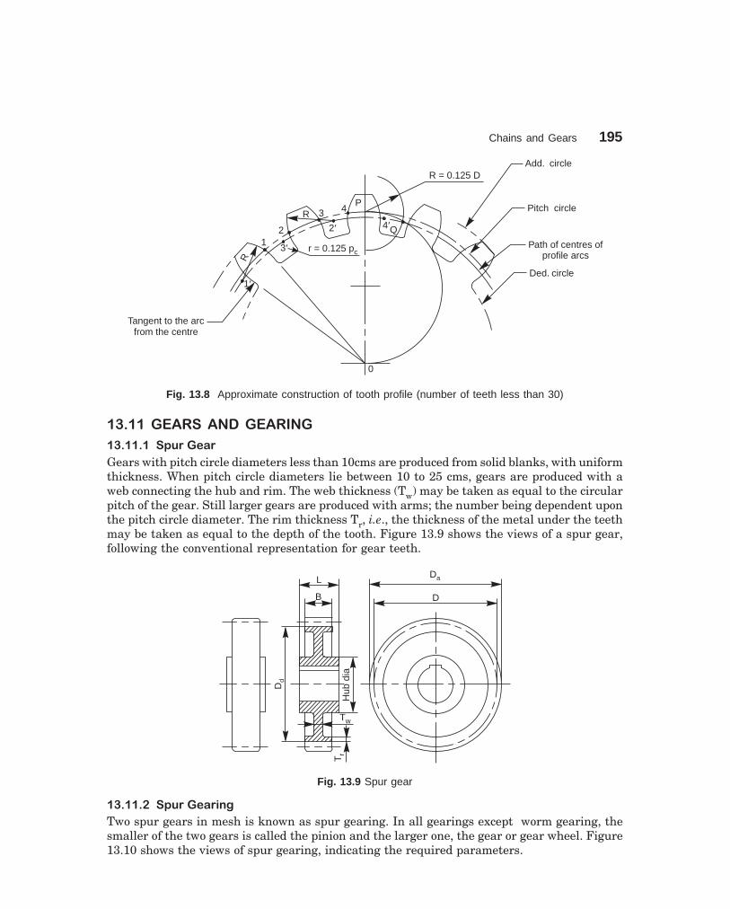
Chains and Gears 195
dharmd:\N-Design\Des13-1.pm5
0
2¢3 4
PR
21
3¢R
Tangent to the arcfrom the centre
Path of centres ofprofile arcs
Ded. circle
Pitch circle
Add. circleR = 0.125 D
r = 0.125 pc
1¢
4�Q
Fig. 13.8 Approximate construction of tooth profile (number of teeth less than 30)
� ����������������
� ��������,%)�'/)
Gears with pitch circle diameters less than 10cms are produced from solid blanks, with uniformthickness. When pitch circle diameters lie between 10 to 25 cms, gears are produced with aweb connecting the hub and rim. The web thickness (Tw) may be taken as equal to the circularpitch of the gear. Still larger gears are produced with arms; the number being dependent uponthe pitch circle diameter. The rim thickness Tr, i.e., the thickness of the metal under the teethmay be taken as equal to the depth of the tooth. Figure 13.9 shows the views of a spur gear,following the conventional representation for gear teeth.
D
DaL
B
Tw
Tr
Hub
dia
Dd
Fig. 13.9 Spur gear
� ��������,%)�'/)+!2
Two spur gears in mesh is known as spur gearing. In all gearings except worm gearing, thesmaller of the two gears is called the pinion and the larger one, the gear or gear wheel. Figure13.10 shows the views of spur gearing, indicating the required parameters.

196 Machine Drawing
dharmd:\N-Design\Des13-1.pm5
q
Cen
tre
dist
ance
Da 2
Dd 2
Da 1
Tr
Tw
L
B
Dd 1
D1
+D
2
Shaft dia.
Hub dia
Shaft dia
Fig. 13.10 Spur gearing
� ���� ���'$+1/$�'/)
Helical gears have teeth inclined to the axis ofrotation at an angle, known as helix angle. Theseare also used to connect parallel shafts. Whenhelical gears are used, the shaft bearings aresubjected to thrust loads which may be resisted byusing a double helicle gear (herring-bone gear). Thisis equivalent to two helical gears of opposite hand,mounted side by side on the same shaft. Thisarrangement, develops opposite thrust reactionsand thus cancel each other.
� ��������'$+1/$�'/)+!2
Two helical gears in mesh is known as helicalgearing. Out of the two gears in mesh, one gearmust have a right hand helix and the other, a lefthand helix as shown in Fig. 13.11. Helical gearingis noiseless in operation because of the moregradual engagement of the teeth during meshing.
� �������3'"'$�'/)
In bevel gears, the teeth are formed on conicalsurfaces and are used for transmitting powerbetween intersecting shafts.
Bevel gears may be classified as straight teeth bevel gears and spiral bevel gears. Hypoidgears are similar to spiral bevel gears, except that the shafts are off-set and non-intersecting.Bevel gears may be used to connect shafts at practically any angle; 90° being the common one.Figure 13.12 shows the views of a bevel gear.
Fig. 13.11 Helical gear and helical gearing

Chains and Gears 197
dharmd:\N-Design\Des13-1.pm5
Shaft dia
a
d
Pitchcone
radius
a
B
Tw
L Hub dia
D
T r
Pitch line
Fig. 13.12 Bevel gear
� �������3'"'$�'/)+!2
Two bevel gears in mesh is known as bevel gearing. In bevel gearing, the pitch cone angles ofthe pinion and gear are to be determined from the shaft angle, i.e., the angle between theintersecting shafts. Figure 13.13 shows two views of a bevel gearing.
a
d
D1
L1
D2
L 2
a
d
Pitc
hco
nera
dius
B
a1a2
B
Hub dia
Shaft
dia
Hubdia
Fig. 13.13 Bevel gearing
� ������4#).�/!5�4#).�'/)�64(''$7
Worm and worm gear in combination, i.e., in meshing is known as worm gearing and is used inspeed reducers requiring large reductions. In worm gearing, the driving member is the worm,which is in the form of a screw, having trapezoidal thread. The worm may have single ormultiple start threads which are left or right hand in nature. The driven member is known asthe worm gear or worm wheel. In one of the designs, the worm gear is in the form of a helicalgear, with teeth cut on a concave shaped periphery and thus enveloping the worm. Figure13.14 shows the worm and worm gear indicated separately and Fig. 13.15, the same in mesh.

198 Machine Drawing
dharmd:\N-Design\Des13-1.pm5
Sha
ft
dia.
L
f
Da D Dd
Shaftdia
B
Tw
Tr
LD
+2a
Dd D Da
Hub dia
Fig.13.14 Worm and worm gear
Shaft dia.
B
Cen
tre
dist
ance
D1
D2
Shaft dia.
Hub dia.
L
90°
Fig. 13.15 Worm gearing

Chains and Gears 199
dharmd:\N-Design\Des13-1.pm5
THEORY QUESTIONS
13.1 What is a gear and what is its function?13.2 How are gears classified? Give their applications.13.3 Define the following terms, as applicable to spur gearing:
(a) pitch circle diameter, (b) addendum, (c) dedendum,(d) pitch point, and (e) pressure angle.
13.4 Why a gear drive is called a positive drive?13.5 What are the commonly used tooth profiles and which one is the most extensively used?13.6 Define an involute curve.13.7 Which will run faster; the larger or smaller of the two meshing gears?13.8 What is a rack and what is its purpose ?13.9 What is the difference between a rack and a pinion?
13.10 Distinguish between:(a) spur and helical gear,(b) single helical gear and double helical gear,(c) spur and bevel gear,(d) gear and gearing,(e) pinion and gear wheel, and(f) worm and worm gear.
DRAWING EXERCISES
13.1 A gear has 30 teeth of involute profile, pitch circle diameter of 180mm and pressure angle of 20°.Draw the profile of four complete teeth for the gear. Also, draw the profile by approximate con-struction method.
13.2 Sketch (a) sectional view from the front and (b) view from the side of a spur gear with a web.13.3 Sketch the views of two gears, a pinion and gear in mesh. Indicate the required parameters.13.4 Sketch a helical gearing, following the conventional representation.13.5 Sketch a bevel gear, indicating the various terms and parameters.13.6 Sketch (a) sectional view from the front and (b) view from the side of a bevel gearing. Indicate
the required parameters.13.7 Through the necessary views, sketch a worm and worm gear separately; indicating the impor-
tant parameters.13.8 Sketch the two views of a worm gearing; indicating the necessary parameters.

200
14������������ ��
���� ��� ��������
The requirements of mass production and interchangeable assembly in industry, demand thatthe components be machined to identical form and size. For this purpose, devices known asjigs and fixtures are used for holding, locating the work and guiding the tools while machining.The use of jigs and fixtures makes possible rapid as well as accurate manufacturing; at thesame time, reducing the production cost.
A jig is a device, which holds and supports the work and also guides the path of thecutting tool, as the operation is performed. Jigs are used extensively for operations such asdrilling, reaming, tapping and counter-boring. The jig need not be secured to the machine.
A fixture is a device which locates and holds the work securely in a definite position. Itis usually secured to the table of the machine and it does not guide the cutting tool. The cuttingtool is either moved into position for the operation or the table is moved under the cutting tool.Fixtures are used while performing milling, turning, honing, broaching, grinding and weldingoperations.
���� � ����������� ���� �� �����
The drawing of a jig or fixture includes a work piece in position. However, the work pieceshould be easily discernible from the jig/fixture. To accomplish this, the work piece is drawn ina chain dotted line, preferably in colour which will be easily distinguished.
The work piece in a fixture/jig drawing is considered transparent. As a result, locators,studs or other parts of fixture/jig passing through the work piece are drawn in full lines insteadof dotted, as shown in Fig. 14.1. Similarly, the parts of the fixture/jig placed behind the workpiece are also drawn.
The work piece is drawn mainly to facilitate design of the jig/fixture. The designer canthus position the locators, clamps and bushes quickly and correctly with respect to the workpiece. It also facilitates tool room and manufacturing engineers to read the jig/fixture drawingand easily understand the functions and requirements of each part.
����� ���� �� � ��
���������������
The jig body is a frame which holds various parts of a jig. It may be a single integral part ofwelded construction or an assembled one. The body must be rigid in construction and at thesame time light in weight for easy handing.
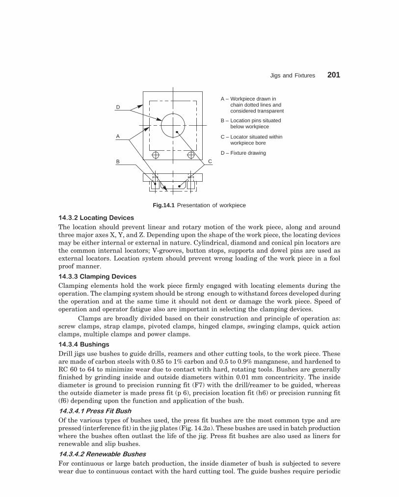
Jigs and Fixtures 201
dharmd:\N-Design\Des14-1.pm5
D
A
B C
A – Workpiece drawn inchain dotted lines andconsidered transparent
B – Location pins situatedbelow workpiece
C – Locator situated withinworkpiece bore
D – Fixture drawing
Fig.14.1 Presentation of workpiece
��������� !"�#���$%� $&
The location should prevent linear and rotary motion of the work piece, along and aroundthree major axes X, Y, and Z. Depending upon the shape of the work piece, the locating devicesmay be either internal or external in nature. Cylindrical, diamond and conical pin locators arethe common internal locators; V-grooves, button stops, supports and dowel pins are used asexternal locators. Location system should prevent wrong loading of the work piece in a foolproof manner.
��������'!()�#���$%� $&
Clamping elements hold the work piece firmly engaged with locating elements during theoperation. The clamping system should be strong enough to withstand forces developed duringthe operation and at the same time it should not dent or damage the work piece. Speed ofoperation and operator fatigue also are important in selecting the clamping devices.
Clamps are broadly divided based on their construction and principle of operation as:screw clamps, strap clamps, pivoted clamps, hinged clamps, swinging clamps, quick actionclamps, multiple clamps and power clamps.
�������*+&,�#�&
Drill jigs use bushes to guide drills, reamers and other cutting tools, to the work piece. Theseare made of carbon steels with 0.85 to 1% carbon and 0.5 to 0.9% manganese, and hardened toRC 60 to 64 to minimize wear due to contact with hard, rotating tools. Bushes are generallyfinished by grinding inside and outside diameters within 0.01 mm concentricity. The insidediameter is ground to precision running fit (F7) with the drill/reamer to be guided, whereasthe outside diameter is made press fit (p 6), precision location fit (h6) or precision running fit(f6) depending upon the function and application of the bush.
���������������� ��
Of the various types of bushes used, the press fit bushes are the most common type and arepressed (interference fit) in the jig plates (Fig. 14.2a). These bushes are used in batch productionwhere the bushes often outlast the life of the jig. Press fit bushes are also used as liners forrenewable and slip bushes.
������������������� ���
For continuous or large batch production, the inside diameter of bush is subjected to severewear due to continuous contact with the hard cutting tool. The guide bushes require periodic
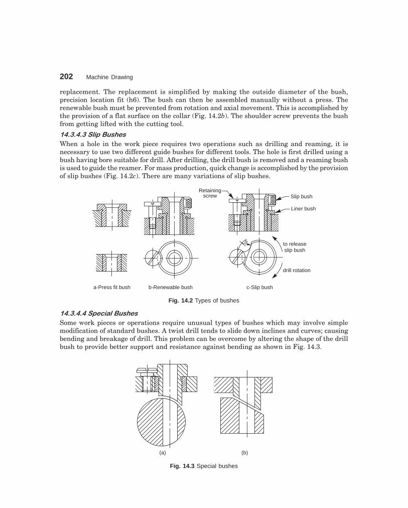
202 Machine Drawing
dharmd:\N-Design\Des14-1.pm5
replacement. The replacement is simplified by making the outside diameter of the bush,precision location fit (h6). The bush can then be assembled manually without a press. Therenewable bush must be prevented from rotation and axial movement. This is accomplished bythe provision of a flat surface on the collar (Fig. 14.2b). The shoulder screw prevents the bushfrom getting lifted with the cutting tool.
�������������� ���
When a hole in the work piece requires two operations such as drilling and reaming, it isnecessary to use two different guide bushes for different tools. The hole is first drilled using abush having bore suitable for drill. After drilling, the drill bush is removed and a reaming bushis used to guide the reamer. For mass production, quick change is accomplished by the provisionof slip bushes (Fig. 14.2c). There are many variations of slip bushes.
a-Press fit bush
Retainingscrew Slip bush
Liner bush
Rto releaseslip bush
drill rotation
b-Renewable bush c-Slip bush
Fig. 14.2 Types of bushes
���������������� ����
Some work pieces or operations require unusual types of bushes which may involve simplemodification of standard bushes. A twist drill tends to slide down inclines and curves; causingbending and breakage of drill. This problem can be overcome by altering the shape of the drillbush to provide better support and resistance against bending as shown in Fig. 14.3.
(a) (b)
Fig. 14.3 Special bushes

Jigs and Fixtures 203
dharmd:\N-Design\Des14-1.pm5
��������� ������������
After fitting the bush in the jig body, there should be sufficient clearance left between the bushand the work piece to permit the chip flow during the machining operation (Fig. 14.4) and alsoburr clearance for ductile materials.
Work piece POOR
Work piece GOOD
Fig. 14.4 Bush clearance
����� -� ����� �.������ ����
Depending upon the construction and method of operation; drill jigs can be broadly classifiedas follows:
1. Plate jigs and channel jigs,2. Angle plate jigs,3. Turn over jigs,4. Leaf or latch jigs,5. Box jigs, and6. Trunion type indexing jigs.
��������,!##$'����
Figure 14.5 shows the assembly drawing of a channel jig with work piece in position.
BushLocator
Clamp
Work piece
Fig. 14.5 Channel jig

204 Machine Drawing
dharmd:\N-Design\Des14-1.pm5
�������*�/����
Figure 14.6 shows the half sectional view from the front and the view from above of theassembled drawing of box jig. This jig is also provided with a latch for clamping and supportingthe work piece when used as a turn-over jig. The use of different types of bushes is also indicatedin the figure.
Clamp
Latch
Workpiece
Four feet
Four feet
Fig. 14.6 Box jig
���0�� ��� �� ��1�������
���0����/"+2$�*!&$
It is used to locate the fixture components and the work piece. It is firmly fastened to themachine table with clamps. In addition, they may be provided with tongues (tenons) that entertable T-slots for aligning the fixture properly with respect to spindle axis.
���0����'!()&
Fixture clamps, apart from clamping the work piece, are required to resist the cutting forces.Hence, they must be sized heavily than the jig clamps and must be properly located.
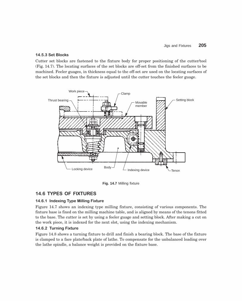
Jigs and Fixtures 205
dharmd:\N-Design\Des14-1.pm5
���0����$"�*'� 3&
Cutter set blocks are fastened to the fixture body for proper positioning of the cutter/tool(Fig. 14.7). The locating surfaces of the set blocks are off-set from the finished surfaces to bemachined. Feeler guages, in thickness equal to the off-set are used on the locating surfaces ofthe set blocks and then the fixture is adjusted until the cutter touches the feeler guage.
Work pieceClamp
Movablemember
Setting block
TenonIndexing deviceBodyLocking device
Thrust bearing
Fig. 14.7 Milling fixture
���4� �.������ ��� ��
���4�����#�$/�#����)$�1�''�#���/"+2$
Figure 14.7 shows an indexing type milling fixture, consisting of various components. Thefixture base is fixed on the milling machine table, and is aligned by means of the tenons fittedto the base. The cutter is set by using a feeler guage and setting block. After making a cut onthe work piece, it is indexed for the next slot, using the indexing mechanism.���4�����+2#�#���/"+2$
Figure 14.8 shows a turning fixture to drill and finish a bearing block. The base of the fixtureis clamped to a face plate/back plate of lathe. To compensate for the unbalanced loading overthe lathe spindle, a balance weight is provided on the fixture base.

206 Machine Drawing
dharmd:\N-Design\Des14-1.pm5
Work piece
Balance weights
Pilot bush
Tool settingpiece
Work piece
Back plate
Fig. 14.8 Turning fixture
���4����$'��#���/"+2$
Figure 14.9 shows a welding fixture for a pipe fabrication. The pipe fabrication consists of 3pipes, 2 channels and 1 gusset channel. The pipes are located and supported by blocks containingsemi-circular grooves. They are clamped by strap clamps. The channels and gusset are locatedand supported by brackets and aligning pins. Later, the welding operation is carried out.

Jigs and Fixtures 207
dharmd:\N-Design\Des14-1.pm5
Pipe fabrication
Locator forchannel
Removablelocation pins
Locator for gusset
Str
apcl
amps
Pip
esu
ppor
tan
dlo
cato
rs
Fixed location pins
Fig. 14.9 Welding fixture
THEORY QUESTIONS
14.1 What is a jig ?14.2 What is a fixture ?14.3 What are the applications of jigs and fixtures ?14.4 How is the work piece represented in a jig or fixture drawing ?14.5 List the various jig components and their uses.14.6 List different types of jigs and sketch the following :
(a) turn over jig, and(b) leaf jig.
14.7 With the help of sketches, describe the different types of bushes.14.8 What is bush clearance and what is its importance ?14.9 List various fixture components and their uses.
14.10 Name the different types of fixtures.

15������������� ��
��������
���� ������ ����
The manufacture of interchangeable parts require precision. Precision is the degree of accuracyto ensure the functioning of a part as intended. However, experience shows that it is impossibleto make parts economically to the exact dimensions. This may be due to,
(i) inaccuracies of machines and tools,(ii) inaccuracies in setting the work to the tool, and
(iii) error in measurement, etc.The workman, therefore, has to be given some allowable margin so that he can produce
a part, the dimensions of which will lie between two acceptable limits, a maximum and aminimum.
The system in which a variation is accepted is called the limit system and the allowabledeviations are called tolerances. The relationships between the mating parts are called fits.
The study of limits, tolerances and fits is a must for technologists involved in production.The same must be reflected on production drawing, for guiding the craftsman on the shopfloor.
���� ����� ����
Following are some of the terms used in the limit system :
����������������
The permissible variation of a size is called tolerance. It is the difference between the maximumand minimum permissible limits of the given size. If the variation is provided on one side ofthe basic size, it is termed as unilateral tolerance. Similarly, if the variation is provided onboth sides of the basic size, it is known as bilateral tolerance.
�������������
The two extreme permissible sizes between which the actual size is contained are called limits.The maximum size is called the upper limit and the minimum size is called the lower limit.
����� ���!������
It is the algebraic difference between a size (actual, maximum, etc.) and the correspondingbasic size.
�����"����#�����!������
It is the algebraic difference between the actual size and the corresponding basic size.
������ �������������
It is the algebraic difference between the maximum limit of the size and the correspondingbasic size.
208

Limits, Tolerances, and Fits 209
dharmd:\N-Design\Des15-1.pm5
�����$���%�����!������
It is the algebraic difference between the minimum limit of the size and the correspondingbasic size.
�����&�����%����
It is the dimensional difference between the maximum material limits of the mating parts,intentionally provided to obtain the desired class of fit. If the allowance is positive, it willresult in minimum clearance between the mating parts and if the allowance is negative, it willresult in maximum interference.
�����'�(�������)�
It is determined solely from design calculations. If the strength and stiffness requirementsneed a 50mm diameter shaft, then 50mm is the basic shaft size. If it has to fit into a hole, then50 mm is the basic size of the hole. Figure 15.1 illustrates the basic size, deviations andtolerances.
Here, the two limit dimensions of the shaft are deviating in the negative direction withrespect to the basic size and those of the hole in the positive direction. The line correspondingto the basic size is called the zero line or line of zero deviation.
Tole
ranc
e
Low
erde
viat
ion
Upp
erde
viat
ion
Hole
Max
imum
diam
eter
Min
imum
diam
eter
Bas
icsi
ze
Shaft
Min
imum
diam
eter
Max
imum
diam
eter
Bas
icsi
ze
Zero line
or line of zerodeviation
Tole
ranc
e
Low
erde
viat
ion
Upp
erde
viat
ion
Fig. 15.1 Diagram illustrating basic size deviations and tolerances
�����*�����+����)�
It is that size, from which the limits of size are derived by the application of tolerances. If thereis no allowance, the design size is the same as the basic size. If an allowance of 0.05 mm forclearance is applied, say to a shaft of 50 mm diameter, then its design size is (50 – 0.05) = 49.95mm. A tolerance is then applied to this dimension.
������,����#�����)�
It is the size obtained after manufacture.
��� ����� �
Great care and judgement must be exercised in deciding the tolerances which may be appliedon various dimensions of a component. If tolerances are to be minimum, that is, if the accuracyrequirements are severe, the cost of production increases. In fact, the actual specified tolerancesdictate the method of manufacture. Hence, maximum possible tolerances must be recommendedwherever possible.

210 Machine Drawing
dharmd:\N-Design\Des15-1.pm5
Fig
. 15
.2 D
egre
e of
acc
urac
y ex
pect
ed o
f m
anuf
actu
ring
proc
ess
16 15 14 13 12 11 10 9 8 7 6 5 4 3 2 1
2550
7510
0
2500
1250 500
250 50 25 5 0
Tolerance,mm
Dia
met
ers
(mm
)
Tole
ranc
egr
ades
16S
and
cast
ing
(app
roxi
mat
ely)
;fla
me
cutti
ng
15S
tam
ping
(app
roxi
mat
ely)
14D
ieca
stin
gor
mou
ldin
g;ru
bber
mou
ldin
g
13P
ress
wor
k;tu
bero
lling
12Li
ght p
ress
wor
k;tu
bedr
awin
g
11D
rillin
g,ro
ugh
turn
ing
and
borin
g;pr
ecis
ion
tube
draw
ing
10M
illin
g,sl
ottin
g,pl
anin
g,m
etal
rolli
ngor
extr
usio
n
9W
orn
caps
tan
orau
tom
atic
,ho
rizon
tal,
orve
rtic
albo
ring
mac
hine
8C
entr
ela
the
turn
ing
and
borin
g,re
amin
g,ca
psta
nor
auto
mat
icin
good
cond
ition
7H
igh
qual
itytu
rnin
g,br
oach
ing,
honi
ng
6G
rindi
ng, f
ine
honi
ng
5B
all b
earin
gs, m
achi
nela
ppin
g,di
amon
dor
fine
borin
g,fin
egr
indi
ng
4G
auge
s,fit
sof
extr
eme
prec
isio
n,pr
oduc
edby
lapp
ing
3G
ood
qual
ityga
uges
, gap
gaug
es
2H
igh
qual
ityga
uges
, plu
gga
uges
1S
lipbl
ocks
, ref
eren
cega
uges

Limits, Tolerances, and Fits 211
dharmd:\N-Design\Des15-1.pm5
Fig. 15.3 Graphical illustration of tolerance zones
Fun
dam
enta
ldev
iatio
n
Neg
ativ
eP
ositi
ve
AE
I
B
C
CDD
E EFF FG G H
JJS
K M N P Zero lineR S T U V X Y Z ZA
ZB
ES
Bas
icsi
ze
ZC
(a) Holes (Internal features)
Fun
dam
enta
ldev
iatio
n
Neg
ativ
eP
ositi
ve
a
es
b
c
cdd
e eff fg g h
jjs
k m n p
Zero line r s t u v x y z zazb
eiB
asic
size
zc
(b) Shafts (external features)
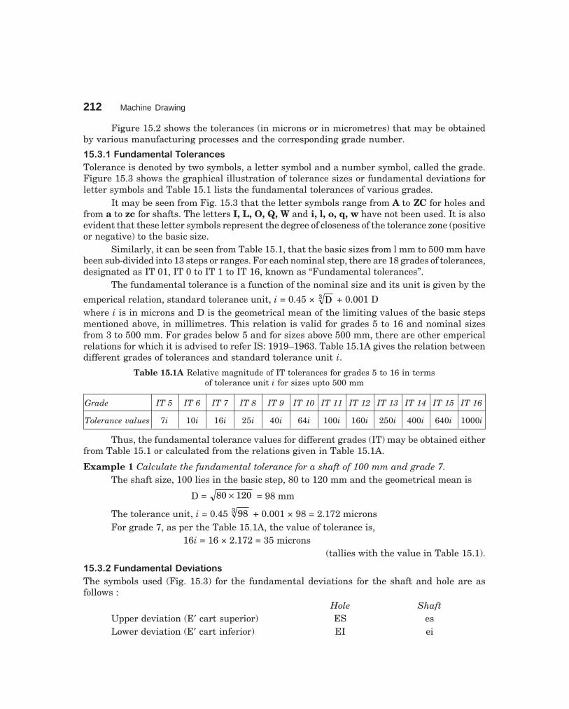
212 Machine Drawing
dharmd:\N-Design\Des15-1.pm5
Figure 15.2 shows the tolerances (in microns or in micrometres) that may be obtainedby various manufacturing processes and the corresponding grade number.
��� ����#�-������������������
Tolerance is denoted by two symbols, a letter symbol and a number symbol, called the grade.Figure 15.3 shows the graphical illustration of tolerance sizes or fundamental deviations forletter symbols and Table 15.1 lists the fundamental tolerances of various grades.
It may be seen from Fig. 15.3 that the letter symbols range from A to ZC for holes andfrom a to zc for shafts. The letters I, L, O, Q, W and i, l, o, q, w have not been used. It is alsoevident that these letter symbols represent the degree of closeness of the tolerance zone (positiveor negative) to the basic size.
Similarly, it can be seen from Table 15.1, that the basic sizes from l mm to 500 mm havebeen sub-divided into 13 steps or ranges. For each nominal step, there are 18 grades of tolerances,designated as IT 01, IT 0 to IT 1 to IT 16, known as “Fundamental tolerances”.
The fundamental tolerance is a function of the nominal size and its unit is given by the
emperical relation, standard tolerance unit, i = 0.45 × D3 + 0.001 Dwhere i is in microns and D is the geometrical mean of the limiting values of the basic stepsmentioned above, in millimetres. This relation is valid for grades 5 to 16 and nominal sizesfrom 3 to 500 mm. For grades below 5 and for sizes above 500 mm, there are other empericalrelations for which it is advised to refer IS: 1919–1963. Table 15.1A gives the relation betweendifferent grades of tolerances and standard tolerance unit i.
Table 15.1A Relative magnitude of IT tolerances for grades 5 to 16 in termsof tolerance unit i for sizes upto 500 mm
Grade IT 5 IT 6 IT 7 IT 8 IT 9 IT 10 IT 11 IT 12 IT 13 IT 14 IT 15 IT 16
Tolerance values 7i 10i 16i 25i 40i 64i 100i 160i 250i 400i 640i 1000i
Thus, the fundamental tolerance values for different grades (IT) may be obtained eitherfrom Table 15.1 or calculated from the relations given in Table 15.1A.
Example 1 Calculate the fundamental tolerance for a shaft of 100 mm and grade 7.The shaft size, 100 lies in the basic step, 80 to 120 mm and the geometrical mean is
D = 80 120× = 98 mm
The tolerance unit, i = 0.45 983 + 0.001 × 98 = 2.172 micronsFor grade 7, as per the Table 15.1A, the value of tolerance is,
16i = 16 × 2.172 = 35 microns(tallies with the value in Table 15.1).
��� ����#�-����������!�������
The symbols used (Fig. 15.3) for the fundamental deviations for the shaft and hole are asfollows :
Hole ShaftUpper deviation (E′ cart superior) ES esLower deviation (E′ cart inferior) EI ei

Limits, T
olerances, and Fits
213
dharmd:\N
-Design\D
es15-1.pm5
Diameter Tolerance Gradessteps in mm
01 0 1 2 3 4 5 6 7 8 9 10 11 12 13 14* 15* 16*
To and inc 3 0.3 0.5 0.8 1.2 2 3 4 6 10 14 25 40 60 100 140 250 400 600
Over 3To and inc 6 0.4 0.6 1 1.5 2.5 4 5 8 12 18 30 48 75 120 180 300 480 750
Over 6To and inc 10 0.4 0.6 1 1.5 2.5 4 6 9 15 22 36 58 90 150 220 360 580 900
Over 10To and inc 18 0.5 0.8 1.2 2 3 5 8 11 18 27 43 70 110 180 270 430 700 1100
Over 18To and inc 30 0.6 1 1.5 2.5 4 6 9 13 21 33 52 84 130 210 330 520 840 1300
Over 30To and inc 50 0.6 1 1.5 2.5 4 7 11 16 25 39 62 100 160 250 390 620 1000 1600
Over 50To and inc 80 0.8 1.2 2 3 5 8 13 19 30 46 74 120 190 300 460 740 1200 1900
Over 80To and inc 120 1 1.5 2.5 4 6 10 15 22 35 54 87 140 220 350 540 870 1400 2200
Over 120To and inc 180 1.2 2 3.5 5 8 12 18 25 40 63 100 160 250 400 630 1000 1600 2500
Over 180To and inc 250 2 3 4.5 7 10 14 20 29 46 72 115 185 290 460 720 1150 1850 2900
Over 250To and inc 315 2.5 4 6 8 12 16 23 32 52 81 130 210 320 520 810 1300 2100 3200
Over 315To and inc 400 3 5 7 9 13 18 25 36 57 89 140 230 360 570 890 1400 2300 3600
Over 400To and inc 500 4 6 8 10 15 20 27 40 63 97 155 250 400 630 970 1550 2500 4000
*Upto 1 mm, Grades 14 to 16 are not provided.
Table 15.1 Fundamental tolerances of grades 01, 0 and 1 to 16 (values of tolerances in microns) (1 micron = 0.001 mm)

214M
achine Draw
ing
dharmd:\N
-Design\D
es15-1.pm5
Fundamental deviation in microns (1 micron = 0.001 mm)
Diameter Upper deviation (es) Lower deviation (ei)steps in mm js+
a b c d e f g h j k
over upto All grades 5.6 7 8 4 to 7 ≤ 3, > 7
— *3 – 270 – 140 – 60 – 20 – 14 – 6 – 2 0 – 2 – 4 – 6 – 0 – 0
3 6 – 270 – 140 – 70 – 30 – 20 – 10 – 4 0 – 2 – 4 — + 1 0
6 10 – 280 – 150 – 80 – 40 – 25 – 13 – 5 0 – 2 – 5 — + 1 0
10 14 – 290 – 150 – 95 – 50 – 32 – 16 – 6 0 ± IT/2 – 3 – 6 — + 1 0
14 18
18 24 – 300 – 160 – 110 – 65 – 40 – 20 – 7 0 – 4 – 8 — + 2 0
24 30
30 40 – 310 – 170 – 120 – 80 – 50 – 25 – 9 0 – 5 – 10 — + 2 0
40 50 – 320 – 180 – 130
50 65 – 340 – 190 – 140 – 100 – 60 – 30 – 10 0 – 7 – 12 — + 2 0
65 80 – 360 – 200 – 150
80 100 – 380 – 220 – 170 – 120 – 72 – 36 – 12 0 – 9 – 15 — + 3 0
100 120 – 410 – 240 – 180
120 140 – 460 – 260 – 200
140 160 – 520 – 280 – 210 – 145 – 85 – 43 – 14 0 – 11 – 18 — + 3 0
160 180 – 580 – 310 – 230
Table 15.2 Fundamental deviations for shafts of types a to k of sizes upto 500mm (contd.)
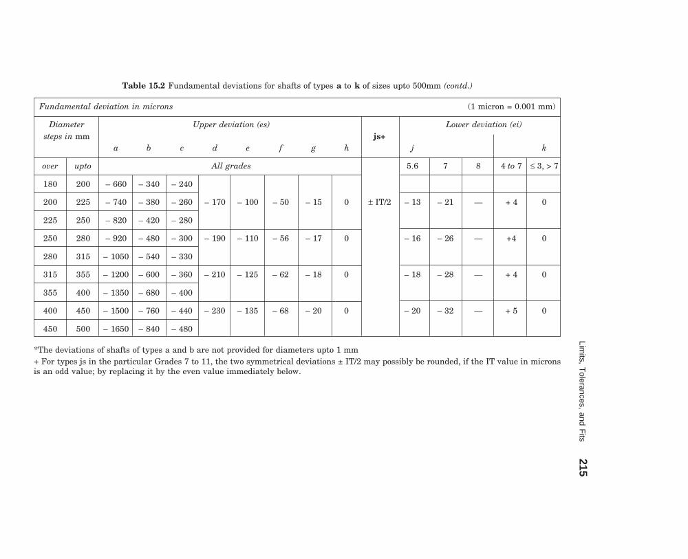
Limits, T
olerances, and Fits
215
dharmd:\N
-Design\D
es15-1.pm5
Fundamental deviation in microns (1 micron = 0.001 mm)
Diameter Upper deviation (es) Lower deviation (ei)steps in mm js+
a b c d e f g h j k
over upto All grades 5.6 7 8 4 to 7 ≤ 3, > 7
180 200 – 660 – 340 – 240
200 225 – 740 – 380 – 260 – 170 – 100 – 50 – 15 0 ± IT/2 – 13 – 21 — + 4 0
225 250 – 820 – 420 – 280
250 280 – 920 – 480 – 300 – 190 – 110 – 56 – 17 0 – 16 – 26 — +4 0
280 315 – 1050 – 540 – 330
315 355 – 1200 – 600 – 360 – 210 – 125 – 62 – 18 0 – 18 – 28 — + 4 0
355 400 – 1350 – 680 – 400
400 450 – 1500 – 760 – 440 – 230 – 135 – 68 – 20 0 – 20 – 32 — + 5 0
450 500 – 1650 – 840 – 480
*The deviations of shafts of types a and b are not provided for diameters upto 1 mm+ For types js in the particular Grades 7 to 11, the two symmetrical deviations ± IT/2 may possibly be rounded, if the IT value in micronsis an odd value; by replacing it by the even value immediately below.
Table 15.2 Fundamental deviations for shafts of types a to k of sizes upto 500mm (contd.)

216M
achine Draw
ing
dharmd:\N
-Design\D
es15-1.pm5
Fundamental deviation in microns (1 micron = 0.001 mm)
Diameter Lower deviations (ei)steps in mm
m n p r s t u v x y z za zb zc
Over Upto All grades
— 3 + 2 + 4 + 6 + 10 + 14 — + 18 — + 20 — + 26 + 32 + 40 + 60
3 6 + 4 + 8 + 12 + 15 + 19 — + 23 — + 28 — + 35 + 42 + 50 + 80
6 10 + 6 + 10 + 15 + 19 + 23 — + 28 — + 34 — + 42 + 52 + 67 + 97
10 14 + 7 + 12 + 18 + 23 + 28 — + 33 — + 40 — + 50 + 64 + 90 + 130
14 18 + 39 + 45 — + 60 + 77 + 108 + 150
18 24 + 8 + 15 + 22 + 28 + 35 — + 41 + 47 + 54 + 63 + 73 + 98 + 136 + 188
24 30 + 41 + 48 + 55 + 64 + 75 + 88 + 118 + 160 + 218
30 40 + 9 + 17 + 26 + 34 + 43 + 48 + 60 + 68 + 80 + 94 + 112 + 148 + 200 + 274
40 50 + 54 + 70 + 81 + 97 + 114 + 136 + 180 + 242 + 325
50 65 + 11 + 20 + 32 + 41 + 53 + 66 + 87 + 102 + 122 + 144 + 172 + 226 + 300 + 405
65 80 + 43 + 59 + 75 + 102 + 120 + 146 + 174 + 210 + 274 + 360 + 480
80 100 + 13 + 23 + 37 + 51 + 71 + 91 + 124 + 146 + 178 + 214 + 258 + 335 + 445 + 585
100 120 + 54 + 79 + 104 + 144 + 172 + 210 + 254 + 310 + 400 + 525 + 690
120 140 + 63 + 92 + 122 + 170 + 202 + 248 + 300 + 365 + 470 + 620 + 800
140 160 + 15 + 27 + 43 + 65 + 100 + 134 + 190 + 228 + 280 + 340 + 415 + 535 + 700 + 900
160 180 + 68 + 108 + 146 + 210 + 252 + 310 + 380 + 465 + 600 + 780 + 1000
Table 15.2 Fundamental deviations for shafts of types m to zc of sizes upto 500 mm (contd.)
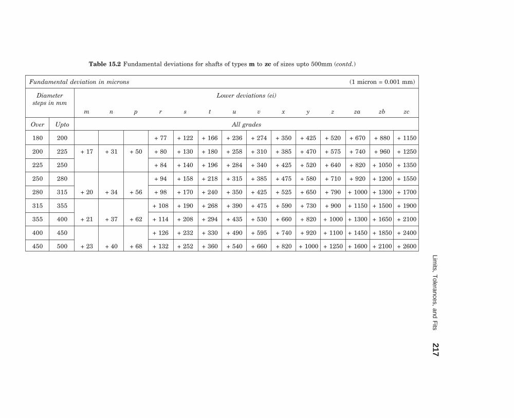
Limits, T
olerances, and Fits
217
dharmd:\N
-Design\D
es15-1.pm5
Fundamental deviation in microns (1 micron = 0.001 mm)
Diameter Lower deviations (ei)steps in mm
m n p r s t u v x y z za zb zc
Over Upto All grades
180 200 + 77 + 122 + 166 + 236 + 274 + 350 + 425 + 520 + 670 + 880 + 1150
200 225 + 17 + 31 + 50 + 80 + 130 + 180 + 258 + 310 + 385 + 470 + 575 + 740 + 960 + 1250
225 250 + 84 + 140 + 196 + 284 + 340 + 425 + 520 + 640 + 820 + 1050 + 1350
250 280 + 94 + 158 + 218 + 315 + 385 + 475 + 580 + 710 + 920 + 1200 + 1550
280 315 + 20 + 34 + 56 + 98 + 170 + 240 + 350 + 425 + 525 + 650 + 790 + 1000 + 1300 + 1700
315 355 + 108 + 190 + 268 + 390 + 475 + 590 + 730 + 900 + 1150 + 1500 + 1900
355 400 + 21 + 37 + 62 + 114 + 208 + 294 + 435 + 530 + 660 + 820 + 1000 + 1300 + 1650 + 2100
400 450 + 126 + 232 + 330 + 490 + 595 + 740 + 920 + 1100 + 1450 + 1850 + 2400
450 500 + 23 + 40 + 68 + 132 + 252 + 360 + 540 + 660 + 820 + 1000 + 1250 + 1600 + 2100 + 2600
Table 15.2 Fundamental deviations for shafts of types m to zc of sizes upto 500mm (contd.)

218M
achine Draw
ing
dharmd:\N
-Design\D
es15-1.pm5
Fundamental deviation in microns (1 micron = 0.001 mm)
Diameter Lower deviations (EI) Upper deviations (ES)steps in mm
A* *B C D E F G H Js+ J K M N
Over Upto All grades 6 7 8 ≤ 8 > 8 ≤ 8 ‡ > 8 ≤ 8 > 8* ≤ 7
— 3* + 270 + 140 + 60 + 20 + 14 + 6 + 2 0 + 2 + 4 + 6 0 0 – 2 – 2 – 4 – 4
3 6 + 270 + 140 + 70 + 30 + 20 + 10 + 4 0 + 5 + 6 + 10 – 1 + ∆ — – 4 + ∆ – 4+∆ – 8 + ∆ 0
6 10 + 280 + 150 + 80 + 40 + 25 + 13 + 5 0 + 5 + 8 + 12 – 1 + ∆ — – 6+ ∆ – 6+∆ – 10 + ∆ 0
10 14 + 290 + 150 + 95 + 50 + 32 + 16 + 6 0 + 6 + 10 + 15 – 1+ ∆ — – 7 + ∆ – 7 – 12 + ∆ 0
14 18 ± IT/2
18 24 + 300 + 160 + 110 + 65 + 40 + 20 + 7 0 + 8 + 12 + 20 – 2 + ∆ — – 8 + ∆ – 8 – 15 + ∆ 0
24 30
30 40 + 310 + 170 + 120 + 80 + 50 + 25 + 9 0 + 10 + 14 + 24 – 2 + ∆ — – 9 + ∆ – 9 – 17 + ∆ 0
40 50 + 320 + 180 + 130
50 65 + 340 + 190 + 140 + 100 + 60 + 30 + 10 0 + 13 + 18 + 28 – 2 + ∆ — – 11+ ∆ – 11 – 20 + ∆ 0
65 80 + 360 + 200 + 150
80 100 + 380 + 220 + 170 + 120 + 72 + 36 + 12 0 + 16 + 22 + 34 – 3 + ∆ — – 13 + ∆ – 13 – 23 + ∆ 0
100 120 + 410 + 240 + 180
Sam
e de
viat
ion
as
for
grad
es >
7 +
∆
Table 15.3 Fundamental deviations for holes of types A to N for sizes upto 500 mm (contd.)A to N
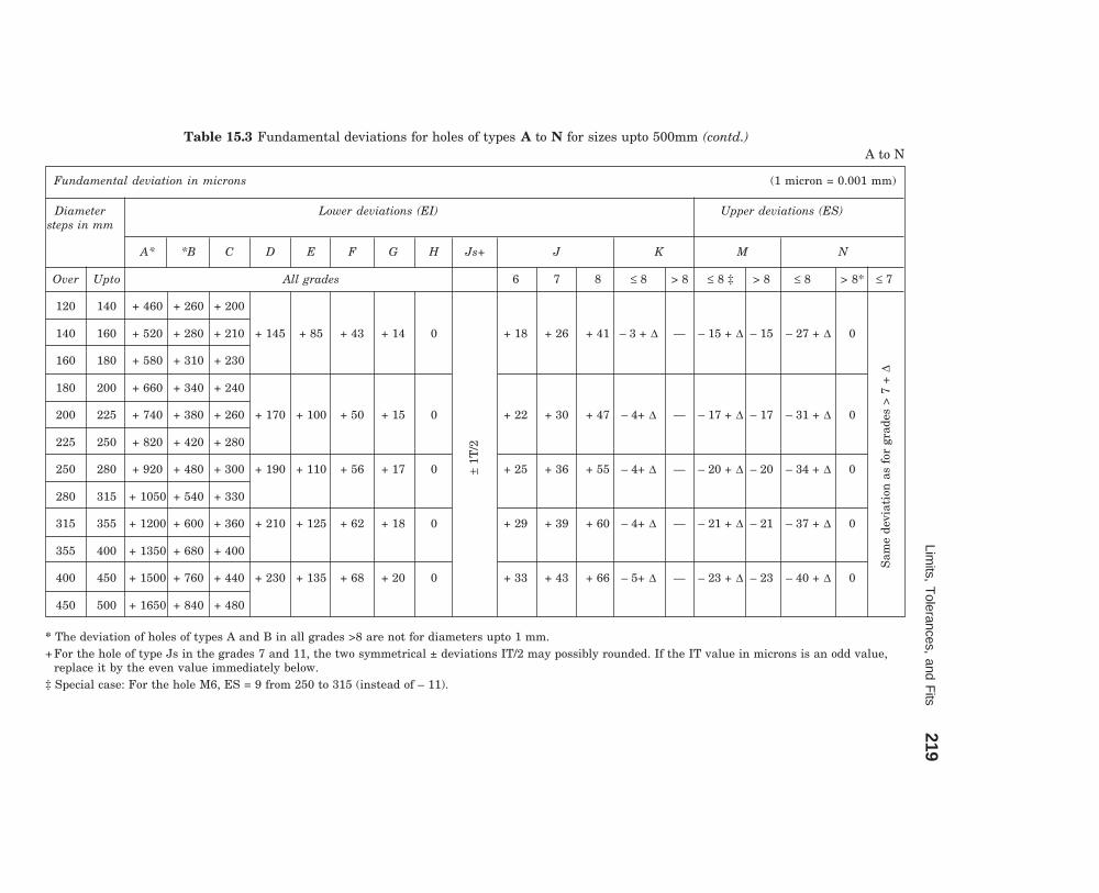
Limits, T
olerances, and Fits
219
dharmd:\N
-Design\D
es15-1.pm5
Fundamental deviation in microns (1 micron = 0.001 mm)
Diameter Lower deviations (EI) Upper deviations (ES)steps in mm
A* *B C D E F G H Js+ J K M N
Over Upto All grades 6 7 8 ≤ 8 > 8 ≤ 8 ‡ > 8 ≤ 8 > 8* ≤ 7
120 140 + 460 + 260 + 200
140 160 + 520 + 280 + 210 + 145 + 85 + 43 + 14 0 + 18 + 26 + 41 – 3 + ∆ — – 15 + ∆ – 15 – 27 + ∆ 0
160 180 + 580 + 310 + 230
180 200 + 660 + 340 + 240
200 225 + 740 + 380 + 260 + 170 + 100 + 50 + 15 0 + 22 + 30 + 47 – 4+ ∆ — – 17 + ∆ – 17 – 31 + ∆ 0
225 250 + 820 + 420 + 280
250 280 + 920 + 480 + 300 + 190 + 110 + 56 + 17 0 + 25 + 36 + 55 – 4+ ∆ — – 20 + ∆ – 20 – 34 + ∆ 0
280 315 + 1050 + 540 + 330
315 355 + 1200 + 600 + 360 + 210 + 125 + 62 + 18 0 + 29 + 39 + 60 – 4+ ∆ — – 21 + ∆ – 21 – 37 + ∆ 0
355 400 + 1350 + 680 + 400
400 450 + 1500 + 760 + 440 + 230 + 135 + 68 + 20 0 + 33 + 43 + 66 – 5+ ∆ — – 23 + ∆ – 23 – 40 + ∆ 0
450 500 + 1650 + 840 + 480
* The deviation of holes of types A and B in all grades >8 are not for diameters upto 1 mm.+ For the hole of type Js in the grades 7 and 11, the two symmetrical ± deviations IT/2 may possibly rounded. If the IT value in microns is an odd value,
replace it by the even value immediately below.‡ Special case: For the hole M6, ES = 9 from 250 to 315 (instead of – 11).
Table 15.3 Fundamental deviations for holes of types A to N for sizes upto 500mm (contd.)A to N
Sam
e de
viat
ion
as
for
grad
es >
7 +
∆
± 1T
/2

220M
achine Draw
ing
dharmd:\N
-Design\D
es15-1.pm5
Fundamental deviation in microns (1 micron = 0.001 mm)
Diameter steps Upper deviations (ES)in mm
P R S T U V X Y Z ZA ZB ZC ∆ in microns*
Over Upto >7 3 4 5 6 7 8
— 3 – 6 – 10 – 14 — – 18 — – 20 — – 26 – 32 – 40 – 60 ∆ = 0
3 6 – 12 – 15 – 19 — – 23 — – 28 — – 35 – 42 – 50 – 80 1 1.5 1 3 4 6
6 10 – 15 – 19 – 23 — – 28 — – 34 — – 42 – 52 – 67 – 97 1 1.5 2 3 6 7
10 14 – 18 – 23 – 28 — – 33 — – 40 — – 50 – 64 – 90 – 130 1 2 3 3 7 9
14 18 – 39 – 45 — – 60 – 77 – 109 – 150
18 24 – 22 – 28 – 35 — – 41 – 47 – 54 – 63 – 73 – 93 – 136 – 188 1.5 2 3 4 8 12
24 30 – 41 – 48 – 55 – 64 – 75 – 88 – 118 – 160 – 218
30 40 – 26 – 34 – 43 – 48 – 60 – 68 – 80 – 94 – 112 – 148 – 200 – 274 1.5 3 4 5 9 14
40 50 – 54 – 70 – 81 – 97 – 114 – 136 – 180 – 242 – 325
50 65 – 32 – 41 – 53 – 65 – 87 – 102 – 122 – 144 – 172 – 226 – 300 – 405 2 3 5 6 11 16
65 80 – 43 – 59 – 75 – 102 – 120 – 146 – 174 – 210 – 274 – 360 – 480
80 100 – 37 – 51 – 71 – 91 – 124 – 146 – 178 – 214 – 258 – 335 – 445 – 585 2 4 5 7 13 19
100 120 – 54 – 79 – 104 – 144 – 172 – 210 – 254 – 310 – 400 – 525 – 690
120 140 – 63 – 92 – 122 – 170 – 202 – 248 – 300 – 365 – 470 – 620 – 800 3 4 6 7 15 23
140 160 – 43 – 65 – 100 – 134 – 190 – 228 – 280 – 340 – 415 – 535 – 700 – 900
160 180 – 68 – 108 – 146 – 210 – 252 – 310 – 380 – 465 – 600 – 780 – 1000
Table 15.3 Fundamental deviations for holes of types P to ZC for sizes upto 500mm (Contd.)P to ZC

Limits, T
olerances, and Fits
221
dharmd:\N
-Design\D
es15-1.pm5
Fundamental deviation in microns (1 micron = 0.001 mm)
Diameter steps Upper deviations (ES)in mm
p R S T U V X Y Z ZA ZB ZC ∆ in microns*
Over Upto >7 3 4 5 6 7 8
180 200 – 77 – 122 – 166 – 236 – 284 – 350 – 425 – 520 – 670 – 880 – 1150
200 225 – 50 – 80 – 130 – 180 – 256 – 310 – 385 – 470 – 575 – 740 – 960 – 1250 3 4 6 9 17 26
225 250 – 84 – 140 – 196 – 284 – 340 – 425 – 520 – 640 – 820 – 1050 – 1350
250 280 – 56 – 94 – 158 – 218 – 315 – 385 – 475 – 580 – 710 – 920 – 1200 – 1550 4 4 7 9 20 29
280 315 – 98 – 170 – 240 – 350 – 425 – 525 – 650 – 790 – 1000 – 1300 – 1700
315 355 – 62 – 108 – 190 – 268 – 390 – 475 – 590 – 730 – 900 – 1150 – 1500 – 1900 4 5 7 11 21 32
355 400 – 114 – 208 – 294 – 435 – 530 – 650 – 820 – 1000 – 1300 – 1650 – 2100
400 450 – 68 – 126 – 232 – 330 – 490 – 595 – 740 – 920 – 1100 – 1450 – 1850 – 2400 5 5 7 13 23 34
450 500 – 132 – 252 – 360 – 540 – 660 – 820 – 1000 – 1250 – 1600 – 2100 – 2600
*In determining K, M, N upto grade 8 and P to ZC upto grade 7, take the ∆ values from the columns on the right.Example: For P7, from diameters 18 to 30 mm, ∆ = 8; hence ES = – 14.
Table 15.3 Fundamental deviations for holes of types P to ZC for sizes upto 500mm (Contd.)P to ZC
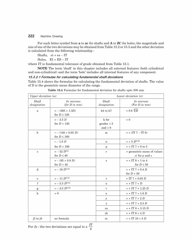
222 Machine Drawing
dharmd:\N-Design\Des15-1.pm5
For each letter symbol from a to zc for shafts and A to ZC for holes; the magnitude andsize of one of the two deviations may be obtained from Table 15.2 or 15.3 and the other deviationis calculated from the following relationship :
Shafts, ei = es – ITHoles, EI = ES – IT
where IT is fundamental tolerance of grade obtained from Table 15.1.NOTE The term ‘shaft’ in this chapter includes all external features (both cylindrical
and non-cylindrical) and the term ‘hole’ includes all internal features of any component.
������������� ������ ���� ��������� ��� ���� ������� �����
Table 15.4 shows the formulae for calculating the fundamental deviation of shafts. The valueof D is the geometric mean diameter of the range.
Table 15.4 Formulae for fundamental deviation for shafts upto 500 mm
Upper deviation (es) Lower deviation (ei)
Shaft In microns Shaft In micronsdesignation (for D in mm) designation (For D in mm)
a = – (265 + 1.3D) k4 to k7 = 0.6 D3
for D ≤ 120
= – 3.5 D k for = 0for D > 120 grades ≤ 3
and ≥ 8
b ≈ – (140 + 0.85 D) m = + (IT 7 – IT 6)for D ≤ 160
≈ – 1.8 D n = + 5 D0.34
for D > 160 p = + IT 7 + 0 to 5
c = – 52 D0.2 r = geometric mean of valuesfor D ≤ 40 ei for p and s
= – (95 + 0.8 D) s = + IT 8 + 1 to 4for D > 40 for D ≤ 50
d = – 16 D0.44 = + IT 7 + 0.4 Dfor D > 50
e = – 11 D0.41 t = IT 7 + 0.63 D
f = – 5.5 D0.41 u = + IT 7 + D
g = – 2.5 D0.34 v = + IT 7 + 1.25 D
h = 0 x = + IT 7 + 1.6 D
y = + IT 7 + 2 D
z = + IT 7 + 2.5 D
za = + IT 8 + 3.15 D
zb = + IT 9 + 4 D
j5 to j8 no formula zc = + IT 10 + 5 D
For Js : the two deviations are equal to ± IT2

Limits, Tolerances, and Fits 223
dharmd:\N-Design\Des15-1.pm5
�������������� ������ ���� ��������� ��� ����������� ����
The fundamental deviation for holes are derived from the formulae, corresponding to the shafts,with the following modifications :
(i) As a general rule, all the deviations for the types of holes mentioned in (ii) and (iii)below, are identical with the shaft deviation of the same symbol, i.e., letter and grade butdisposed on the other side of the zero line. For example, the lower deviation EI for the hole isequal to the upper deviation es of the shaft of the same letter symbol but of opposite sign.
(ii) For the holes of sizes above 3 mm and of type N and of grade 9 and above, the upperdeviation, ES is 0.
(iii) For the holes of size above 3 mm of types J, K, M and N of grades upto and inclusiveof 8 and for the types P to ZC of grades upto and inclusive of 7, the upper deviation ES is equalto the lower deviation ei of the shaft of same letter symbol but one grade finer (less in number)and of opposite sign, increased by the difference between the tolerances of the two grades inquestion.
Example 2 Calculate the fundamental deviations for the shaft sizes given below :(a) 30 e8 (b) 50 g6 (c) 40 m6.From Table 15.4, the deviations for shafts are obtained :(a) The upper deviation es for the shaft e
= – 11 D0.41
The value for D = 18 30× = 23.24 mm.
Hence, es = – 40 microns (tallies with the value in Table 15.2).(b) The upper deviation es for the shaft g
= – 2.5 D0.34
The value for D = 30 50× = 38.73 mm.
Hence, es = – 9 microns (tallies with the value in Table 15.2)(c) The lower deviation ei for the shaft m
= + (IT 7 – IT 6)From the Table 15.1, the size 40 is in the range 30 and 50 and hence the mean diameter
D, is 38.73 mm
Tolerance unit i = 0.45 D3 + 0.001 D= 1.58 microns
The fundamental tolerance for grade 7, from the Table 15.1 is 16i, i.e., 25 microns.The fundamental tolerance for grade 6 is 10i or 16 microns.Hence, ei = 25 (IT 7) – 16 (IT 6) = + 9 microns (tallies with the value in Table 15.2).
Example 3 Calculate the fundamental deviations for the hole sizes given below :(a) 40 D9 (b) 65 F8.From Table 15.4, the deviations for holes also can be obtained (article 15.3.2.2).(a) The lower deviation EI for the hole D is given by
EI = + 16 D0.44, where D = 30 50× = 38.73 mm
Thus, EI = 80 microns (tallies with the value in Table 15.3).

224 Machine Drawing
dharmd:\N-Design\Des15-1.pm5
(b) Lower deviation EI for the hole F
= + 5.5 D0.41, where D = 50 80×
Hence, EI = 30 microns (tallies with the value in Table 15.3).
Example 4 A journal bearing consists of a bronze bush of diameter 100 mm fitted into a housingand a steel shaft of 50 mm diameter, running in the bush, with oil as lubricant. Determine theworking dimensions of (a) bore of the housing, (b) bush and (c) shaft. Calculate the maximumand minimum interference or clearance.
Step 1: Select the nature of assembly or fit based on the function. Referring to Table15.6, the fits to be employed are selected as below:
(a) for the bush and housing, H7/p6 (interference fit),(b) for the shaft and bush, H7/f7 (normal running fit).Step 2: Obtain the tolerances on the linear dimensions of the parts. From Table 15.1, the
fundamental tolerances (IT) for different grades, based on the size are :(a) for dia. 100 and grade 6 = 22 microns,(b) for dia. 100 and grade 7 = 35 microns,(c) for dia. 50 and grade 7 = 25 microns.Step 3: Obtain the fundamental deviations based on the type of hole/shaft and thus the
respective sizes. From Table 15.2,(a) for a hole of type H (housing)
lower deviation, EI = 0.000 upper deviation, ES = EI + IT
= 0.035 mm
Hence, dimension of the housing bore = 100 0.0000.035
++
.(b) for a shaft of type p (bush),
lower deviation, ei = + 0.037 (Table 15.2) upper deviation, es = ei + IT
= 0.037 + 0.022 = 0.059 mm
Hence, the outside size of the bush = 100 0.0370.059
++
.(c) for a hole of type H (bush),
lower deviation, EI = 0.000upper deviation, ES = EI + IT
= 0.025 mm
Hence, the bore of the bush = 50 0.0000.025
++
.(d) for a shaft of type f,
upper deviations, es = – 0.025 (Table 15.2) lower deviation, ei = es – IT
= – 0.025 – 0.025 = – 0.05 mm
Hence, shaft dimension is = 50 0.0500.025
−–

Limits, Tolerances, and Fits 225
dharmd:\N-Design\Des15-1.pm5
Step 4: Calculate the interference/clearance
(a) between the bush and housing :
Maximum interference = 100.00 – 100.059
= – 0.059 mm
Minimum interference = 100.035 – 100.037
= – 0.002 mm
(b) between the bush and shaft :
Maximum clearance = 50.025 – 49.050
= + 0.075 mm
Minimum clearance = 50.000 – 49.075
= + 0.025 mm
��� � ����.�-��/�0�����+������������������1����������+���-�!�-#�������������2
There are three methods used in industries for placing limit dimensions or tolerancing individualdimensions.
Method 1
In this method, the tolerance dimension is given by its basic value, followed by a symbol,comprising of both a letter and a numeral. The following are the equivalent values of the termsgiven in Fig. 15.4 :
+ 0.021φ 25H7 = φ 25 + 0.000
+ 0.058 10H10 = 10 + 0.000
+ 0.280 40C11 = 40 + 0.120
– 0.000 10h9 = 10 – 0.036
– 0.000φ 25h9 = φ 25 – 0.052
– 0.000
φ 40h11 = φ 40 – 0.160
The terms φ 25H7, 10H10 and 40C11 refer to internal features, since the terms involvecapital letter symbols. The capital letter ‘H’ signifies that the lower deviation is zero and thenumber symbol 7 signifies the grade, the value of which is 21 microns (Table 15.1) which in-turn is equal to the upper deviation. The capital letter C signifies that the lower deviations is120 microns (Table 15.3). The value of the tolerance, corresponding to grade 11 is 160 microns(Table 15.1). The upper deviation is obtained by adding 160 to 120 which is equal to 280 micronsor 0.28 mm.
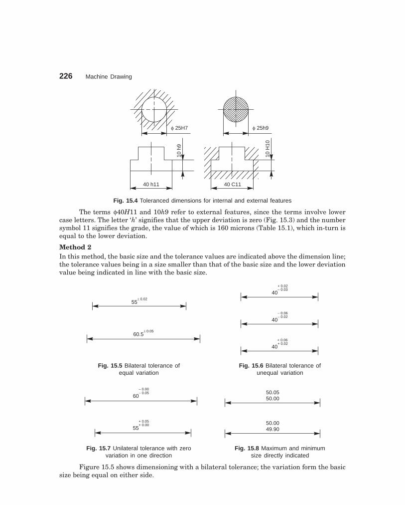
226 Machine Drawing
dharmd:\N-Design\Des15-1.pm5
f 25H7 f 25h9
40 C11
10H
10
40 h1110
h9
Fig. 15.4 Toleranced dimensions for internal and external features
The terms φ40H11 and 10h9 refer to external features, since the terms involve lowercase letters. The letter ‘h’ signifies that the upper deviation is zero (Fig. 15.3) and the numbersymbol 11 signifies the grade, the value of which is 160 microns (Table 15.1), which in-turn isequal to the lower deviation.
Method 2In this method, the basic size and the tolerance values are indicated above the dimension line;the tolerance values being in a size smaller than that of the basic size and the lower deviationvalue being indicated in line with the basic size.
55� 0.02
40– 0.03
60.5� 0.05
40– 0.02
40+ 0.02
+ 0.02
– 0.06
+ 0.06
Fig. 15.5 Bilateral tolerance of Fig. 15.6 Bilateral tolerance ofequal variation unequal variation
60– 0.05 50.05
50.00
50.0049.90
– 0.00
55+ 0.00+ 0.05
Fig. 15.7 Unilateral tolerance with zero Fig. 15.8 Maximum and minimumvariation in one direction size directly indicated
Figure 15.5 shows dimensioning with a bilateral tolerance; the variation form the basicsize being equal on either side.

Limits, Tolerances, and Fits 227
dharmd:\N-Design\Des15-1.pm5
Figure 15.6 shows dimensioning with a bilateral tolerance; the variation being unequal.Figure 15.7 shows dimensioning with a unilateral tolerance; the variation being zero in
one direction.
Method 3In this method, the maximum and minimum sizes are directly indicated above the dimensionline (Fig. 15.8).
When assembled parts are dimensioned, the fit is indicated by the basic size common toboth the components, followed by the hole tolerance symbol first and then by the shaft tolerancesymbol (e.g., φ 25 H7/h6, etc., in Fig. 15.9).
f 25 H7/h6
f 25 H7h6
HOLE 25f+ 0.000
SHAFT 25f– 0.013
+ 0.021
+ 0.000
Fig. 15.9 Toleranced dimensioning of assembled parts
���" ����
The relation between two mating parts is known as a fit. Depending upon the actual limits ofthe hole or shaft sizes, fits may be classified as clearance fit, transition fit and interference fit.
���"���� ������������
It is a fit that gives a clearance between the two mating parts.
����������������� �����
It is the difference between the minimum size of the hole and the maximum size of the shaft ina clearance fit.
����������������� �����
It is the difference between the maximum size of the hole and the minimum size of the shaft ina clearance or transition fit.
The fit between the shaft and hole in Fig. 15.10 is a clearance fit that permits a minimumclearance (allowance) value of 29.95 – 29.90 = + 0.05 mm and a maximum clearance of + 0.15 mm.
���"������������������
This fit may result in either an interference or a clearance, depending upon the actual valuesof the tolerance of individual parts. The shaft in Fig. 15.11 may be either smaller or larger

228 Machine Drawing
dharmd:\N-Design\Des15-1.pm5
than the hole and still be within the prescribed tolerances. It results in a clearance fit, whenshaft diameter is 29.95 and hole diameter is 30.05 (+ 0.10 mm) and interference fit, when shaftdiameter is 30.00 and hole diameter 29.95 (– 0.05 mm).
Maximum size of shaft
Shaft tolerance
Max. clearance
Min. clearance (Allowance)
Min dia. of shaft
f 29.90
f 29.85
f 29.95 Min. size of hole =
basic sizef 30.00
Hole tolerance
Max. dia of hole
Fig. 15.10 Clearance fit
Max. size of shaft
Shaft tolerance
Max. clearance
Max. interference (Allowance)
Min. dia. of shaft
f 30.00
f 29.95
f 29.95 Min. size of hole =
basic sizef 30.05
Hole tolerance
Max. dia. of hole
Fig. 15.11 Transition fit
���������������������
If the difference between the hole and shaft sizes is negative before assembly; an interferencefit is obtained.
������������������ �� � ��
It is the magnitude of the difference (negative) between the maximum size of the hole and theminimum size of the shaft in an interference fit before assembly.

Limits, Tolerances and Fits 229
dharmd:\N-Design\Des15-2.pm5
������������������ �� � ��
It is the magnitude of the difference between the minimum size of the hole and the maximumsize of the shaft in an interference or a transition fit before assembly.
The shaft in Fig. 15.12 is larger than the hole, so it requires a press fit, which has aneffect similar to welding of two parts. The value of minimum interference is 30.25 – 30.30= – 0.05 mm and maximum interference is 30.15 – 30.40 = – 0.25 mm.
Max. size of shaft
Shaft tolerance
Max. interference (Allowance)
Min. size of hole =
basic size
Hole tolerance
Max. diameter of hole
f 30.40
Min. dia. of shaft
f 30.15
f 30.30
f 30.25
Min. interference
Fig. 15.12 Interference fit
Figure 15.13 shows the conventional representation of these three classes of fits.
Hole Hole
ShaftShaft
Clearance fit
HoleShaft
ShaftShaft
Transition fit
Hole Hole
ShaftShaft
Interference fit
Fig. 15.13 Schematic representation of fits

230 Machine Drawing
dharmd:\N-Design\Des15-2.pm5
�������������� ���� ����� ���� ����������
In working out limit dimensions for the three classes of fits; two systems are in use, viz., thehole basis system and shaft basis system.
������������� �����������
In this system, the size of the shaft is obtained by subtracting the allowance from the basic sizeof the hole. This gives the design size of the shaft. Tolerances are then applied to each partseparately. In this system, the lower deviation of the hole is zero. The letter symbol for thissituation is ‘H’.
The hole basis system is preferred in most cases, since standard tools like drills, reamers,broaches, etc., are used for making a hole.
������������ ���� ���������
In this system, the size of the hole is obtained by adding the allowance to the basic size of theshaft. This gives the design size for the hole. Tolerances are then applied to each part. In thissystem, the upper deviation of the shaft is zero. The letter symbol for this situation is ‘h’.
The shaft basis system is preferred by (i) industries using semi-finished shafting as rawmaterials, e.g., textile industries, where spindles of same size are used as cold-finished shaftingand (ii) when several parts having different fits but one nominal size is required on a singleshaft.
Figure 15.14 shows the representation of the hole basis and the shaft basis systemsschematically. Table 15.5 gives equivalent fits on the hole basis and shaft basis systems toobtain the same fit.
Hole
HoleShaft Shaft
Shaft HoleHole
Hole
Bas
icsi
ze
Shaft
ShaftShaft
Shaft
Shaft
HoleHole
Hole
Zeroline
Examples taken fromshaft-basis system
Examples taken fromhole-basis system
Fig. 15.14 Examples illustrating shaft basis and hole basis systems
Application of various types of fits in the hole basis system is given in Table 15.6.
Table 15.5. Equivalent fits on the hole basis and shaft basis systems
Clearance Transition Interference
Hole basis Shaft basis Hole basis Shaft basis Hole basis Shaft basis
H7 – c8 C8 – h7 H6 – j5 J6 – h5 H6 – n5 N6 – h5H8 – c9 C9 – h8 H7 – j6 J7 – h6H11 – c11 C11 – h11 H8 – j7 J8 – h7 H6 – p5 P6 – h5
H7 – p6 p7 – h6H7 – d8 D8 – h7 H6 – k5 K6 – h5H8 – d9 D9 – h8 H7 – k6 K7 – h6 H6 – r5 R6 – h5
(Contd.)...

Limits, Tolerances and Fits 231
dharmd:\N-Design\Des15-2.pm5
H11 – d11 D11 – h11 H8 – k7 K8 – h7 H7 – r6 R7 – h6H6 – e7 E7 – h6 H6 – m5 M6 – h5 H6 – s5 S6 – h5H7 – e8 E8 – h7 H7 – m6 M7 – h6 H7 – s6 S7 – h6H8 – e8 E8 – h8 H8 – m7 M8 – h7 H8 – s7 S8 – h7H6 – f6 F6 – h6 H7 – n6 N7 – h6 H6 – t5 T6 – h5H7 – f7 F7 – h7 H8 – n7 N8 – h7 H7 – t6 T7 – h6H8 – f8 F8 – h8 H8 – t7 T8 – h7
H8 – p7 P8 – h7H6 – g5 G6 – h5 H6 – u5 U6 – h5H7 – g6 G7 – h6 H8 – r7 R8 – h7 H7 – u6 U7 – h6H8 – g7 G8 – h7 H8 – u7 U8 – h7
Table 15.6. Types of fits with symbols and applications
Type of fit Symbol of fit Examples of application
Interference fit
Shrink fit H8/u8 Wheel sets, tyres, bronze crowns on worm wheelHeavy drive fit H7/s6 hubs, couplings under certain conditions, etc.Press fit H7/r6 Coupling on shaft ends, bearing bushes in hubs, valveMedium press fit H7/p6 seats, gear wheels.
Transition fit
Light press fit H7/n6 Gears and worm wheels, bearing bushes, shaft andwheel assembly with feather key.
Force fit H7/m6 Parts on machine tools that must be changed withoutdamage, e.g., gears, belt pulleys, couplings, fit bolts,inner ring of ball bearings.
Push fit H7/k6 Belt pulleys, brake pulleys, gears and couplings aswell as inner rings of ball bearings on shafts foraverage loading conditions.
Easy push fit H7/j6 Parts which are to be frequently dismantled but aresecured by keys, e.g., pulleys, hand-wheels, bushes,bearing shells, pistons on piston rods, change geartrains.
Clearance fit
Precision sliding fit H7/h6 Sealing rings, bearing covers, milling cutters onmilling mandrels, other easily removable parts.
Close running fit H7/g6 Spline shafts, clutches, movable gears in change geartrains, etc.
Normal running fit H7/f7 Sleeve bearings with high revolution, bearings onmachine tool spindles.
Easy running fit H8/e8 Sleeve bearings with medium revolution, greaselubricated bearings of wheel boxes, gears sliding onshafts, sliding blocks.
Loose running fit H8/d9 Sleeve bearings with low revolution, plastic materialbearings.
Slide running fit H8/c11 Oil seals (Simmerrings) with metal housing (fit inhousing and contact surface on shaft), multi-splineshafts.

232 Machine Drawing
dharmd:\N-Design\Des15-2.pm5
���� ����� ����� �������� 0�������
�������������-#�����
Tolerances of size are not always sufficient to provide the required control of form. For example,in Fig. 15.15 a the shaft has the same diameter measurement in all possible positions but isnot circular; in Fig. 15.15 b, the component has the same thickness throughout but is not flatand in Fig. 15.15 c, the component is circular in all cross-sections but is not straight. The formof these components can be controlled by means of geometrical tolerances.
fD
fD
(a) (b) (c)
Fig. 15.15 Errors of form
�������������3��������
It is a variation of the actual condition of a form feature (surface, line) from geometrically idealform.
����� ��0��������3��������
It is a variation of the actual position of the form feature from the geometrically ideal position,with reference to another form (datum) feature.
�����"��4��������������������
Geometrical tolerance is defined as the maximum permissible overall variation of form orposition of a feature.
Geometrical tolerances are used,(i) to specify the required accuracy in controlling the form of a feature,
(ii) to ensure correct functional positioning of the feature,(iii) to ensure the interchangeability of components, and(iv) to facilitate the assembly of mating components.
������������������5���
It is an imaginary area or volume within which the controlled feature of the manufacturedcomponent must be completely contained (Figs. 15.16 a and b).
�����$����/��������
����������� ��
It is a theoretically exact geometric reference (such as axes, planes, straight lines, etc.) towhich the tolerance features are related (Fig. 15.17).

Limits, Tolerances and Fits 233
dharmd:\N-Design\Des15-2.pm5
Element
Tolerance zone
a – Tolerance area
Tolerance zone Element
b – Tolerance volume
Fig. 15.16
����������� ����� ���
A datum feature is a feature of a part, such as an edge, surface, or a hole, which forms the basisfor a datum or is used to establish its location (Fig. 15.17).
0.02 A Datum letter
Tolerance value
Tolerance symbol
Leader line
Arrow
Tolerancedfeature
(a)
(b)
A
Datum letter
Datum triangle
Datum feature
Fig. 15.17
����������� ����� ����
The datums are indicated by a leader line, terminating in a filled or an open triangle (Fig. 15.17).
����������� ��������
To identify a datum for reference purposes, a capital letter is enclosed in a frame, connected tothe datum triangle (Fig. 15.17).
The datum feature is the feature to which tolerance of orientation, position and run-outare related. Further, the form of a datum feature should be sufficiently accurate for its purposeand it may therefore be necessary in some cases to specify tolerances of form from the datumfeatures.
Table 15.7 gives symbols, which represent the types of characteristics to be controlledby the tolerance.

234 Machine Drawing
dharmd:\N-Design\Des15-2.pm5
�����&����-������+�4��������������������������.�����%��+
To eliminate the need for descriptive notes, geometrical tolerances are indicated on drawingsby symbols, tolerances and datums, all contained in compartments of a rectangular frame, asshown in Fig. 15.17.
�����'����-���������/ �����#��� ��������-
The feature controlled by geometrical tolerance is indicated by an arrowhead at the end of aleader line, from the tolerance frame.
Table 15.7 Symbols representing the characteristics to be toleranced
Characteristics to be toleranced Symbols
Straightness
Flatness
Form of single features Circularity (roundness)
Cylindricity
Profile of any line
Profile of any surface
Parallelism
Orientation of related features Perpendicularity (squareness)
Angularity
Position
Position of related features Concentricity and coaxiality
Symmetry
Run-out
The tolerance frame is connected to the tolerance feature by a leader line, terminatingwith an arrow in the following ways:
1. On the outline of the feature or extension of the outline, but not a dimension line,when the tolerance refers to the line or surface itself (Figs. 15.18 a to c), and
2. On the projection line, at the dimension line, when the tolerance refers to the axis ormedian plane of the part so dimensioned (Fig. 15.18 d) or on the axis, when thetolerance refers to the axis or median plane of all features common to that axis ormedian plane (Fig. 15.18 e).

Limits, Tolerances and Fits 235
dharmd:\N-Design\Des15-2.pm5
a – Correct b – Correct c – Incorrect
d – Correct e – Correct
Fig. 15.18 Indication of feature controlled (outline or surface only)
�����*������-��-�������%�-������-#���6
Comparison of systems of indication of tolerances of form and of position as per IS: 3000(part-1)-1976 and as prevalent in industry are shown in Table 15.8.
Table 15.8 Systems of indication of tolerances of form and of position
As per the standard As prevalent in industry
1. Straightness tolerance
– f 0.08Permissibleunstraightness 0.08
2. Flatness tolerance
0.08Permissibleunevenness 0.08
3. Circularity tolerance
O 0.1Permissibleovality 0.2
(Contd.)

236 Machine Drawing
dharmd:\N-Design\Des15-2.pm5
4. Cylindricity tolerance
0.1Permissiblenon-cylindricity 0.2
5. Parallelism tolerance
0.01 D
D
Permissiblenon-parallelism 0.01
6. Perpendicularity tolerance
A
0.08 A^
90° ±
30¢
Permissibleperpendicularity 5¢
7. Angularity tolerance
A
40°
Ð 0.08 A
40° ± 1°
Permissibleequiangularity 30¢
8. Concentricity and coaxiality tolerance
f 0.01 AA
0.00
5
(Contd.)

Limits, Tolerances and Fits 237
dharmd:\N-Design\Des15-2.pm5
9. Symmetry tolerance
0.08 AA
.04
10. Radial run-out
0.1 D
D
Permissible crossindicator runout(Between centres) 0.1
11. Axial run-out
0.1 D
D
Permissible longitudinalindicator runout (Betweencentres) 0.1
THEORY QUESTIONS
15.1 Define the terms: (a) basic size, (b) limits, (c) allowance, (d) tolerance and (e) deviation.
15.2 What is an unilateral tolerance and what is a bilateral tolerance?
15.3 What is fundamental tolerance and how tolerance is denoted?
15.4 What are the different methods used for placing limit dimensions?
15.5 What is meant by the term “fit” and how are fits classified?
15.6 Differentiate between clearance fit and transition fit.
15.7 Name the two systems that are in use for finding out limit dimensions.
15.8 Differentiate between hole basis system and shaft basis system.
15.9 When is a shaft basis system preferred to hole basis system?
15.10 What is meant by tolerance of (a) form and (b) position?
15.11 Explain the term tolerance zone with reference to the tolerance of form and position.
15.12 Define the following terms:
(a) datum, (b) datum feature, (c) datum triangle and (d) datum letter.
15.13 With the help of a sketch, show how geometrical tolerances are indicated on a drawing.
15.14 With the help of a sketch, show how the tolerance frame is connected to the feature controlled.
15.15 What are the various ways by which a tolerance frame is connected to the tolerance feature?Explain with the help of sketches.
15.16 With the help of sketches, show how the geometrical tolerances are indicated, as prevalent inindustry, for the following cases:
(a) parallelism, (b) perpendicularity, (c) symmetry and (d) radial run out.

238 Machine Drawing
dharmd:\N-Design\Des15-2.pm5
DRAWING EXERCISES
15.1 Calculate the maximum and minimum limits for both the shaft and hole in the following; usingthe tables for tolerances and name the type of fit obtained:(a) 45H8/d7 (b) 180H7/n6 (c) 120H7/s6(d) 40G7/h6 (e) 35 C11/h10
15.2 The dimensions of a shaft and a hole are given below:Shaft, Basic size = 60mm and given as 60 – 0.020Hole, Basic size = 60mm and given as 60 – 0.005Find out:(a) Tolerance of shaft (b) Tolerance of hole (c) Maximum allowance(d) Minimum allowance (e) Type of fit
15.3 A schematic representation of basic size and its deviations are given in Fig. 15.19. Calculate thefollowing in each case for a shaft of 50 mm basic size:(a) Upper deviation (b) Lower deviation (c) Tolerance(d) Upper limit size (e) Lower limit size
+24
–5
(a) (b)
–70
+30
+10
(c)
–20
–40
+40
0(e)
(d)
Fig. 15.19
15.4 A schematic representation of basic size and its deviations are given in Fig. 15.20. Identify them.
Zero line
C
DE
B A
Fig. 15.20
15.5 A 30mm diameter hole is made on a turret lathe to the limits, 30.035 and 30.00. The followingtwo grades of shafts are used to fit in the hole:(a) φ29.955mm and 29.925mm, and (b) φ30.055mm and 30.050mm.Calculate the maximum tolerance, clearance and indicate the type of fit in each case by a sketch.

Limits, Tolerances and Fits 239
dharmd:\N-Design\Des15-2.pm5
15.6 Compute the limit dimensions for a clearance fit on the hole basis system, for a basic size of40 mm diameter, with a minimum clearance of 0.05 mm; with the tolerance on the hole being0.021 and the tolerance on the shaft being 0.15 mm.
15.7 Find the limit dimensions for an interference fit on the shaft basis system for the above problemand compare the dimensions of the shaft and hole.
15.8 Determine the type of fit and calculate the clearance and or interference for the schematic toler-ance zones shown in Fig. 15.21.
–36
–50(c)
–23
0
+18
00
+10
–12 –8
–25–23
(b)(a)
Hole
Shaft
Fig. 15.21
15.9 Suggest suitable fits and their letter and tolerance grades for the components shown in Fig. 15.22.
D
FE
C
GG
AA
BB
A – Shaft rotating in bushB – Bush fixed in housingC – Bush is secured on to the gearD – Base plate of the gear unit is secured on to the
casting by cylindrical pinE – Gear with the bush rotating on to the pinF – Pin is secured on to the base plateG – Bush with plate
Fig. 15.22
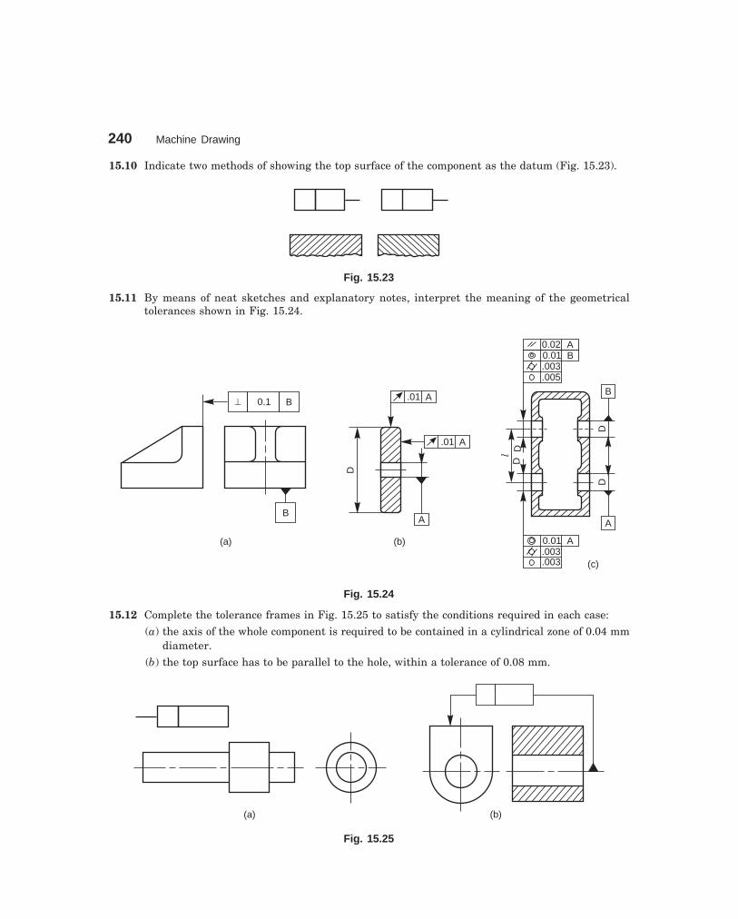
240 Machine Drawing
dharmd:\N-Design\Des15-2.pm5
15.10 Indicate two methods of showing the top surface of the component as the datum (Fig. 15.23).
Fig. 15.23
15.11 By means of neat sketches and explanatory notes, interpret the meaning of the geometricaltolerances shown in Fig. 15.24.
^ 0.1 B
B
(a)
.01 A
.01 A
A
(b)
D0.020.01.003.005
AB
0.01.003
A
A
B
DD
DD
l
(c).003
Fig. 15.24
15.12 Complete the tolerance frames in Fig. 15.25 to satisfy the conditions required in each case:
(a) the axis of the whole component is required to be contained in a cylindrical zone of 0.04 mmdiameter.
(b) the top surface has to be parallel to the hole, within a tolerance of 0.08 mm.
(a) (b)
Fig. 15.25
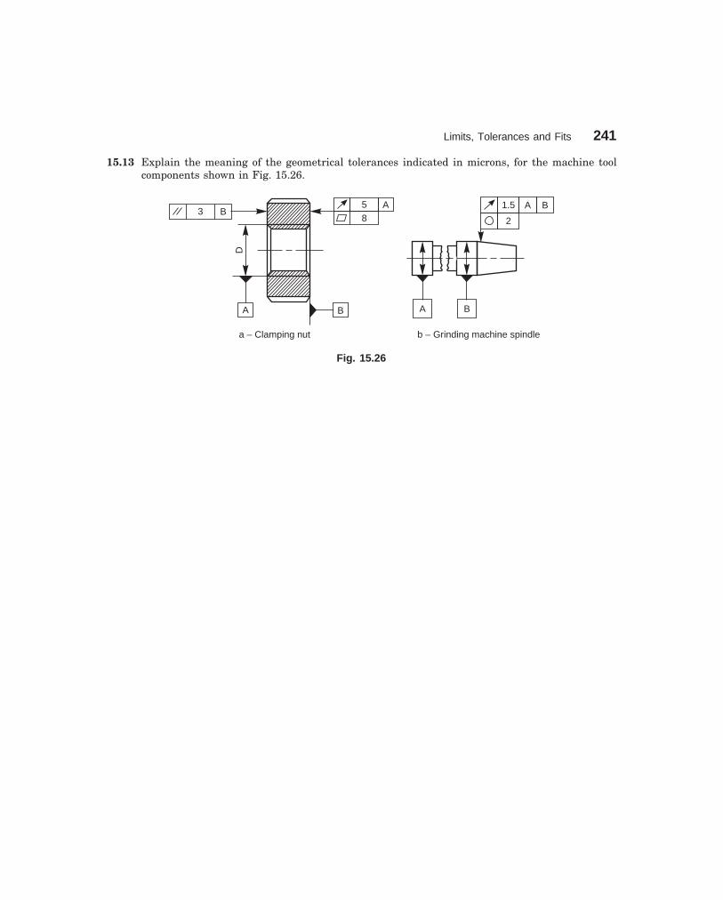
Limits, Tolerances and Fits 241
dharmd:\N-Design\Des15-2.pm5
15.13 Explain the meaning of the geometrical tolerances indicated in microns, for the machine toolcomponents shown in Fig. 15.26.
A B
D
5 A8
3 B
a – Clamping nut
A B
1.5
2
A B
b – Grinding machine spindle
Fig. 15.26

16���������������
242
�� ����������
It is not possible to achieve in practice, a geometrically ideal surface of a component and hence,production drawings of components must also contain information about the permissible surfaceconditions. Machine components which have undergone machining operation, when inspectedunder magnification, will have some minute irregularities. The actual surface condition willdepend upon the finishing process adopted.
The properties and performance of machine components are affected by the degree ofroughness of the various surfaces. The higher the smoothness of the surface, the better is thefatigue strength and corrosion resistance. Friction between mating parts is also reduced dueto better surface finish.
��� �������� �������
The geometrical characteristics of a surface include,1. Macro-deviations,2. Surface waviness, and3. Micro-irregularities.The surface roughness is evaluated by the height, Rt and mean roughness index Ra of
the micro-irregularities. Following are the definitions of the terms indicated in Fig. 16.1:
H
Rt Rf
Af
DfMf
LB
h h1 2 hn0
–
+
Fig. 16.1

Surface Roughness 243
dharmd:\N-Design\Des16-1.pm5
���� ��������������������
It is the profile of the actual surface obtained by finishing operation.
������������� ��������������
It is the profile to which the irregularities of the surface are referred to. It passes through thehighest point of the actual profile.
����!������"������������
It is the profile, parallel to the reference profile. It passes through the lowest point B of theactual profile.
����#��$�� ������������
It is that profile, within the sampling length chosen (L), such that the sum of the material-filled areas enclosed above it by the actual profile is equal to the sum of the material-void areasenclosed below it by the profile.
����%�����&'��'(����)����*+�����
It is the distance from the datum profile to the reference profile.
�������$�� ����*+ �,,�� -�.����
It is the arithmetic mean of the absolute values of the heights hi between the actual and meanprofiles. It is given by,
Ra = 1/L x
x L
=
=
� 0 |hi|dx , where L is the sampling length
����/�������������*+ �,,���"0��
The surface roughness number represents the average departure of the surface from perfectionover a prescribed sampling length, usually selected as 0.8 mm and is expressed in microns.The measurements are usually made along a line, running at right angle to the general directionof tool marks on the surface. Surface roughness values are usually expressed as the Ra valuein microns, which are determined from (Fig. 16.1),
Ra = h h h h
nn1 2 3+ + + +...
The surface roughness may be measured, using any one of the following :
1. Straight edge
2. Surface guage
3. Optical flat
4. Tool maker’s microscope
5. Profilometer
6. Profilograph
7. TalysurfTable 16.1 shows the surface roughness expected from various manufacturing processes.

244 Machine Drawing
dharmd:\N-Design\Des16-1.pm5
Table 16.1 Surface roughness expected from various manufacturing processes
Sl.No.
ManufacturingProcess
1 Sand casting
2Permanent mouldcasting
3
4
5
6
7
Die casting
High pressurecasting
Forging
Flame cutting,sawing & ChippingRadial cut-offsawing
Extrusion
Hot rolling
8
9
10
11
12
13
14
15
16
17
18
19
20
21
22
23
24
25
26
27
Hand grinding
Disc grinding
Filing
Planing
Shaping
Drilling
Turning & Milling
Boring
Reaming
Broaching
Hobbing
Surface grinding
Cylindrical grinding
Honing
Lapping
Polishing
Burnishing
Super finishing
R in ma m
0.01
2
0.02
5
0.05
0
0.10
0.20
0.40
0.80
1.6
3.2
6.3
12.5
25 50 100
200
505
6.30.8
3.20.8
20.320.32
502.52.5
281.6
50.160.16
1006.3
6.31
256.3
251.6
250.250.25
501.6
251.6
20201.6
250.320.32
6.30.4
3.20.4
3.20.4
3.20.4
50.0630.063
50.0630.063
0.40.0250.025
0.160.160.0120.012
0.160.160.040.04
0.80.040.04
0.320.320.0160.016

Surface Roughness 245
dharmd:\N-Design\Des16-1.pm5
��! $�������� �1$23�
This article deals with the symbols and other additional indications of surface texture, to beindicated on production drawings.
The basic symbol consists of two legs of unequal length, inclined at approximately 60° tothe line, representing the surface considered (Fig. 16.2a). This symbol may be used where it isnecessary to indicate that the surface is machined, without indicating the grade of roughnessor the process to be used.
If the removal of material is not permitted, a circle is added to the basic symbol, asshown in Fig. 16.2b. This symbol may also be used in a drawing, relating to a productionprocess, to indicate that a surface is to be left in the state, resulting from a precedingmanufacturing process, whether this state was achieved by removal of material or otherwise.If the removal of material by machining is required, a bar is added to the basic symbol, asshown in Fig. 16.2c. When special surface characteristics have to be indicated, a line is addedto the longer arm of the basic symbol, as shown in Fig. 16.2d.
(a) (b) (c) (d)
Fig. 16.2
��# ���������� �� �������� �������
The value or values, defining the principal criterion of roughness, are added to the symbol asshown in Fig. 16.3.
(a)
a a
(b) (c)
a
Fig. 16.3
A surface texture specified,
as in Fig. 16.3a, may be obtained by any production method.
as in Fig. 16.3b, must be obtained by removal of material by machining.
as in Fig. 16.3c, must be obtained without removal of material.
When only one value is specified to indicate surface roughness, it represents the maximumpermissible value. If it is necessary to impose maximum and minimum limits of surfaceroughness, both the values should be shown, with the maximum limit, a1, above the minimumlimit, a2 (Fig. 16.4a).

246 Machine Drawing
dharmd:\N-Design\Des16-1.pm5
(a)
a2
a1
(b)
a
Milled
(d)
c
(e)
T
a2 a1
Chromium plated
(c)
�
Fig. 16.4
The principal criterion of surface roughness, Ra may be indicated by the correspondingroughness grade number, as shown in Table 16.2.
Table 16.2 Equivalent surface roughness symbols
Roughness values Roughness RoughnessRa µm grade number grade symbol
50 N12
25 N11
12.5 N10
6.3 N9
3.2 N8
1.6 N7
0.8 N6
0.4 N5
0.2 N4
0.1 N3
0.05 N2
0.025 N1
��#� ��� -������ �����4�����������������*+ �,,��+��������,���,
In certain circumstances, for functional reasons, it may be necessary to specify additionalspecial requirements, concerning surface roughness.
If it is required that the final surface texture be produced by one particular productionmethod, this method should be indicated on an extension of the longer arm of the symbol asshown in Fig. 16.4b. Also, any indications relating to treatment of coating may be given on theextension of the longer arm of the symbol.
Unless otherwise stated, the numerical value of the roughness, applies to the surfaceroughness after treatment or coating. If it is necessary to define surface texture, both beforeand after treatment, this should be explained by a suitable note or as shown in Fig. 16.4c.

Surface Roughness 247
dharmd:\N-Design\Des16-1.pm5
If it is necessary to indicate the sampling length, it should be selected from the seriesgiven in ISO/R 468 and be stated adjacent to the symbol, as shown in Fig. 16.4d. If it is necessaryto control the direction of lay, it is specified by a symbol added to the surface roughness symbol,as shown in Fig. 16.4e.
NOTE The direction of lay is the direction of the predominant surface pattern, ordinar-ily determined by the production method employed.
Table 16.3 shows the symbols which specify the common directions of lay.
Table 16.3 Symbols specifying the directions of lay
Symbol Interpretation
Parallel to the plane of projectionof the view in which the symbol isused
Perpendicular to the plane ofprojection of the view in which thesymbol is used
Crossed in two slant directionsrelative to the plane of projectionof the view in which the symbol isused
Multi-directional
Approximately circular, relative tothe centre of the surface to whichthe symbol is applied
Approximately radial, relative tothe centre of the surface to whichthe symbol is applied
M
C
R
=
�
X
M
C
R
Direction oflay
T
Direction oflay
X
Direction oflay

248 Machine Drawing
dharmd:\N-Design\Des16-1.pm5
��#����� -������ ��� �$��+� � *�����5� ��
When it is necessary to specify the value of the machining allowance, this should be indicatedon the left of the symbol, as shown in Fig. 16.5a. This value is expressed normally in millimetres.
Figure 16.5b shows the various specifications of surface roughness, placed relative tothe symbol.
(a)
5
(b)
b
c (f)a
de
Fig. 16.5
��#�!��� -������ ,��� ������������*+ �,,��)"0��,�� ����5� *,
The symbol and the inscriptions should be so oriented, that they may be read from the bottomor the right hand side of the drawing (Fig. 16.6a). If it is not practicable to adopt this generalrule, the symbol may be drawn in any position (Fig. 16.6b), provided that it does not carry anyindications of special surface texture characteristics.
acb
abc
a
a
(a) (b)
Fig. 16.6
The symbol may be connected to the surface by a leader line, terminating in an arrow.The symbol or the arrow should point from outside the material of the piece, either to the linerepresenting the surface, or to an extension of it (Fig. 16.6a)
In accordance with the general principles of dimensioning, the symbol is only used oncefor a given surface and, if possible, on the view which carries the dimension, defining the sizeor position of the surface (Fig. 16.7).
If the same surface roughness is required on all the surfaces of a part, it is specified,either by a note near a view of the part (Fig. 16.8), near the title block, or in the space devotedto general notes, or following the part number on the drawing.
If the same surface roughness is required on the majority of the surfaces of a part, it isspecified with the addition of, the notation, except where otherwise stated (Fig. 16.9a), or abasic symbol (in brackets) without any other indication (Fig. 16.9b), or the symbol or symbols(in brackets) of the special surface roughness or roughnesses (Fig. 16.9c).
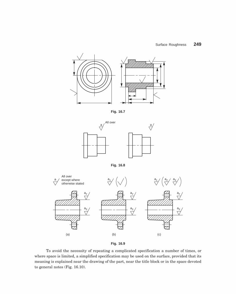
Surface Roughness 249
dharmd:\N-Design\Des16-1.pm5
Fig. 16.7
aAll over
a
Fig. 16.8
a3
a2
a3
a2
(a) (b)
a3
a2
(c)
aAll overexcept whereotherwise stated
a1 a1 a2 a3
Fig. 16.9
To avoid the necessity of repeating a complicated specification a number of times, orwhere space is limited, a simplified specification may be used on the surface, provided that itsmeaning is explained near the drawing of the part, near the title block or in the space devotedto general notes (Fig. 16.10).

250 Machine Drawing
dharmd:\N-Design\Des16-1.pm5
z
y
z a2
a1b
c
de=
y=
3, 2
4
(a) (b)
Fig. 16.10
THEORY QUESTIONS
16.1 What is the importance of surface roughness ?16.2 Mention the geometrical characteristics of a surface.16.3 Define the following terms :
(a) reference profile, (b) datum profile,(c) mean roughness index (d) surface roughness number.
16.4 What are the various means that are used to determine the surface roughness value ?16.5 How surface roughness values are indicated on a drawing ?16.6 Indicate how various surface roughness specifications are placed relative to the symbol.16.7 Indicate roughness grade symbols for the following roughness grade numbers :
(a) N 12 (b) N 10 (c) N 8(d) N 6 (e) N 2
16.8 What is meant by direction of lay? How is it shown on a drawing ? Sketch the symbols related tothe common directions of lay.
DRAWING EXERCISES
16.1 Indicate the roughness grade symbols used in shop floor practice, with their range of roughnessvalues.
16.2 What are the roughness values that can be normally obtained by (a) fine turning, (b) machinereaming, (c) milling, (d) precision grinding and (e) chrome plating.
16.3 Show how the roughness is indicated on the component for the following situations.(a) surface to be obtained by any production method,(b) surface to be obtained without removal of material(c) surface to be coated, and(d) surface to be given a machining allowance.
16.4 With examples, show the method of indicating surface roughness on the following components :(a) symmetrical surfaces requiring the same quality,(b) cylindrical part, and (c) same surface quality all over.
16.5 Suggest suitable surface finish values and the process of obtaining them for the following compo-nents :(a) precision drill sleeve, (b) grade 1 milling machine column guide-ways,(c) splines on a shaft, (d) faces of a milling arbor spacer, and(e) precision lathe bed guide-ways.
���� ����������
In many ways, learning to read a drawing is the same as learning to read a language. Blueprintis the common name of the copies taken from an original drawing, usually drawn on a tracingpaper. The copies may be obtained by way of reprographic processes, viz., blueprinting, ammoniaprinting, xerox copying, copy of a photo film, etc., but the colour of the print has nothing to dowith the name “blueprint”.
For blueprint reading and understanding the drawing, one must have a thoroughknowledge of the principles of drawing and orthographic projections. The knowledge of variousmanufacturing processes and the sequence of operations required to obtain the finished shape,intended by the designer, also helps in interpreting the drawings.
In this chapter, the examples chosen help providing guidelines to enable students tounderstand the shape and size of a component, in the case of component drawings, and also itslocation, in the case of assembly drawings. While reading the drawings, the details such asshape, size, through dimensions, notes and material to be used, and additional notes to theworkman on machining, surface finish, tolerances, etc., are to be noted carefully.
���� ����� �
����������������������
Rear tool post is generally used on capstan lathes, mainly for parting-off operations. It is fixedon the cross-slide in the slots, provided at the rear side of the lathe. Study the drawing shownin Fig. 17.1 and answer the following :
1. What is the overall size of the tool post?— 102mm × 70mm × 62mm
2. How many bolts are provided for fixing the tool, and what is the size of each bolt?—3, M10
3. What type of tool can be used with it?— Parting tool
4. What is the maximum height of the tool holder?— 25mm
5. How many screws are provided to locate the tool?— 2
6. How is the tool holder fixed to the cross slide?— By 2 Nos. of M6 Hex. socket headed set screws
17�� ������� ����
251

252 Machine Drawing
dharmd:\N-Design\Des17-1.pm5
7. What is the purpose of the threaded hole marked ‘X’?— For adjusting the tool height, by means of a screw
8. Explain the note—4 HOLES, M10.—There are three tapped holes in the body to clamp the tool in position by screwsand the fourth tapped hole is at the bottom of the base. The size of the tap is 10mm.
16
6
50 8
20
2 HOLES, M6 26 62
R 6
X 88
16
16 12
2 HOLES, M 10DEEP 16
DIA 10 C BORE,DEEP 8
�
70
32
22
f 14
8
642 f 25
41
82
102
10
4 HOLES,M 10
70
Fig. 17.1 Rear tool post
����������� �!���"#$
The view from the front and the view from above of a pump housing is shown in Fig. 17.2. Readthe drawing and answer the following :
1. What is the overall size of the housing?—178mm × 152mm × 102mm
2. What is the gasket size required for the top surface?—134mm × 95mm
3. There are 4 tapped holes on the top. What is the size of the tap?—M6
4. Specify the location of the holes on the front face.—2 HOLES, M10 DEEP 25 AT 120 PCD
5. Explain the note—4 HOLES, M10 DEEP 25.—There are two holes in the front and two more holes similarly placed at the back,each having a thread of nominal diameter of 10mm and depth of 25mm.

Blueprint Reading 253
dharmd:\N-Design\Des17-1.pm5
15°
3857
R 12.5
X
15°
50
12.5
134
67B10
1084 HOLES, M 10
DEEP 25
f 90
120 PCD
45°
A
R 12
76
152
16
D
76
178
10
R12.5
95
47.5
63
4 HOLES, M 6
C
10
M20
50
R 12.5R 12.5
12.5
25 102
R 10
Fig. 17.2 Pump housing
6. What is the size of the opening at the top?—89mm × 50mm
7. What is the diameter of the gasket required for the front cover?—144 mm
8. What is the corner radius of the top flange?—R 10
9. Locate the centre point of tapped holes M 6.—10mm × 10mm from the flange edges at each corner
10. Find the dimensions A, B, C and D.—A = 9.5mm, B = 114mm, C = 9.5mm and D = 20mm

254 Machine Drawing
dharmd:\N-Design\Des17-1.pm5
11. What is the slope of the recess in the housing base?—15°
12. What are the other dimensions of the recess?—57mm × 12.5mm × 38mm
13. What is the width and thickness of the base?—63mm × 16mm
14. What is the width of the rib marked ‘X’?—25 mm
�����%���������&���'��
Study the two orthographic views and the local sections of the gear box cover shown in Fig. 17.3and answer the following :
1. How is the cover fixed to the gear box?— By means of 6 screws
2. What is the size of the thread?—M 10
3. What is the thread size ‘A’ shown in the view from the front?—M 20
4. What are the values of the dimensions B, C, D and E in the view from the front?—B = φ 21, C = φ 18, D = 6 mm, and E = 34 mm
5. What is the thickness of the cover at section B-B?—6 mm
6. What will be the gasket size, if required?—262mm × 124mm
7. How many tapped holes are there on the side opening of the cover and what is thesize?—4, M 6
8. What is the material and method of manufacture suggested for the cover?—Cast iron, CO2 sand casting
9. What are the dimensions of F, G and H marked in the view from above.—F = 24 mm, G = R 9 and H = R 10
10. What is the maximum height of the cover?—90 mm
11. What is the wall thickness of the cover and the fillet radius where no size is men-tioned?—Thickness = 6 mm, fillet radius = 3 mm
�����(����������� �)��'�
A steam stop valve is mounted on the steam pipe, close to the engine to regulate the flow ofsteam through pipes and shut-off completely when not required. It is operated by means of ahand wheel. These valves have a low lift and hence can be closed and opened quickly.
Figure 17.4 shows the sectional view of an assembly drawing of a steam stop valve. Thehand wheel (5) which operates the valve (2) is fitted on to the spindle (4). The spindle is screwedinto the bush (6) which is fixed to the bridge (7) by two countersunk screws (8). The bridge is
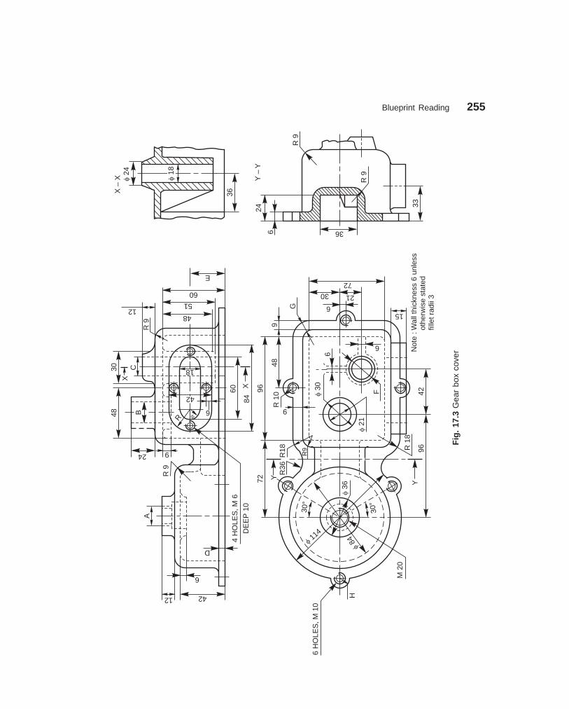
Blueprint Reading 255
dharmd:\N-Design\Des17-1.pm5
Fig
. 17
.3 G
ear
box
cove
r
D
12 42
6
AR
9
12
E
60
51
48
XC30
48 B
R9
924
R
4H
OLE
S,M
6
DE
EP
10
42 60
84X
f24
X–
X f18
36
33
36
24
6
Y–
Y
R9
R9
f 114
f84
f36
M20
30°
30°
H
6H
OLE
S,M
10
Y
YR
36R
18
R9
7296
R10
9
489
G
f21
f30
6
F
6
72
2130
6R
18
9642
15
Not
e:W
allt
hick
ness
6un
less
othe
rwis
est
ated
fille
t rad
ii3
18
6
R
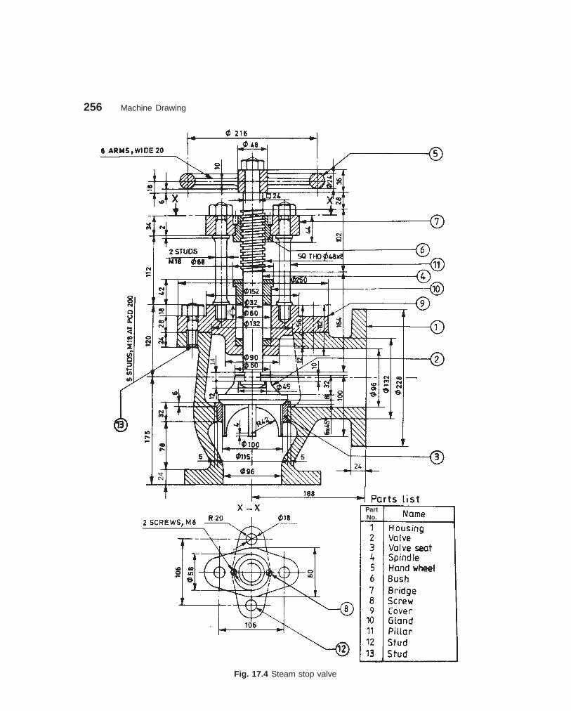
256 Machine Drawing
dharmd:\N-Design\Des17-1.pm5
Fig. 17.4 Steam stop valve
25
14
24
PartNo.

Blueprint Reading 257
dharmd:\N-Design\Des17-1.pm5
connected to the cover (9) by two pillars (11). The bottom end of the spindle is connected to thevalve in such a way that it transmits vertical motion but not the rotational one.
The steam passage is completely closed when the valve is in its bottom most position,but as it is lifted, the passage slowly increases. Thus, steam regulation is achieved. The gland(10), which is secured to the cover (9) with two studs (12), prevents steam leakage through thecover. The stop valve is connected to the steam pipe, through flanges provided in the housing (1).
Read the assembly drawing and answer the following :1. What is the material of the spindle and what is its thread specification?
—Mild steel, square thread: SQ40 × 8 mm2. What is the total length of the spindle?
—374 mm3. What is the thread size of the studs (13)?
— M 184. What is the material of the gland? And what is its bore and height?
—Bronze, Bore-φ 32, Height-42 mm5. What are the flange bore and outside diameter?
—φ 96 and φ 2286. What is the size of the hand wheel and its arm thickness?
—φ 240, 10 mm7. What is the size of the spindle, where the hand wheel is fitted?
—SQ 24 mm8. What is the pitch of the spindle thread and the depth?
—8 mm and 4 mm9. What is the size of the slot in the valve that fits on to the spindle?
—φ 45 × 12 mm10. What is the taper on the valve seat?
—45°11. What is the height of the stud nut?
—18 mm12. Wht is the length of the stud (13)?
—70 mm13. What is the thickness of the valve flange?
—24 mm14. How many studs are there to fix the cover (9) and how they are located?
—5 Nos. at 200 PCD15. What is the bush height?
—44 mm
���% � ���� �
���%����*���������!���"#$
The orthographic views of a worm gear casing are shown in Fig. 17.5. Read the drawing andanswer the following:

258 Machine Drawing
dharmd:\N-Design\Des17-1.pm5
1. What is the centre distance between the worm and worm wheel?2. What is the screw size used to fix the gear shaft in position?3. What is the thickness of the worm wheel casing?4. Find the dimensions of A, B, C, D and E, marked in the view from the front.5. Find the dimensions of F, G and H, marked in the view from the left.6. What is the approximate overall size of the casing?7. What is the size of the fillet radius?
R 25
R 20
G
X
H
3 10
22 12 20 258
f11
0
f48
f30
f30 f32
f50
8 35
4835
f 20
X
2317
62
f 12
f 22
55
R 1250
R 31
f 90
E
M 10
5540
25D C
f22
f25
f22
f40
B
M 10
185
35 10075
2225 A 22
F
Fig. 17.5 Worm gear housing
���%������##�+���
The working drawing of a connector is shown in Fig. 17.6. Study the drawing and answer thefollowing:
1. What is the significance of the length of the connector 165 mm, shown within thebrackets?
2. What is the size of the knurled portion of the component?3. What is the size of the keyweay?4. Specify the taper.5. Specify the threads on the component.6. What is the depth of the drilled hole?7. What is the counterbore specification at the internal thread opening?8. What is the purpose of the groove marked ‘X’ and its enlarged view shown?9. Explain the note 4HOLES, DIA6.
10. Where are the holes drilled?11. What is the meaning of 4 × 45°?12. How is the keyway cut?13. Explain the meaning of the surface finish symbol shown.

Blueprint Reading 259
dharmd:\N-Design\Des17-1.pm5
14. Explain the note at × (5 : 1).15. Explain the linear and angular tolerances provided.16. Explain φ 50 f 7.17. What type of tolerance is given on φ 16?18. Explain SR 5.19. What is the length of the internal thread?
X
X
KNURL
DIA
80B
EF
OR
E
KN
UR
LIN
G
0.8 4 × 45°
f50
f 7
f25
2
M 20 × 2.5
22 MIN. LENGTH 30 60 2525
±0.1
12540(165)
2035
M20
×2.
5
26f50
2 × 45°
14°30 ± 0°10¢¢
XR
2m
ax
SR 5
14R
12 14
5 max.
R 1.25max 60°
f16.4
016
.07
(5 : 1) Detail at X
X – X 4 HOLES,
DIA 6
45
45°
f 65f 65
Fig. 17.6 Connector
���%�%���,��������������
The assembled views of a four way tool post are shown in Fig. 17.7. Study the drawing andanswer the following :
1. How is the tool post fixed on the compound slide?2. What is the size of the square tool post body?3. What is the maximum size of the tool or tool holder that can be fixed in the tool post?4. How many tools can be fixed in the tool post?5. How is the tool indexed and the tool post clamped?6. What is the fit between the body (1) and stud (6)?7. What is the thread size on the stud?8. How many steel balls with springs are used in the unit?9. How many square headed screws are used for clamping all the 4 tools?
10. What is the maximum diameter of the clamp?11. Specify size of the stud.12. What is the size of the base plate that fits into the tool holder body?

260 Machine Drawing
dharmd:\N-Design\Des17-1.pm5
Fig. 17.7 Square tool post
SQ 22
75
562
7
2620
SR 50
3 6
f 46M 24
X – X
55
5
7
4
114R 20f
10
1
f 9.525
17
45
2118
3040
SQ 80
f 60
3434
99f 28f 28
143 M 16
910
4 HOLES, DIA 16 C’BOREDIA 28, DEEP 17
X
X
120f 62
4H
OLE
S,D
IA9.
5,
EQ
UI–
SP,
PC
D10
5
8H
OLE
S, M
16
SQ 150
SQ 120SQ 106
S.No.
Name Material Qty
1
2
3
4
5
6
7
8
9
10
11
Tool holder
Base plate
Clamp
Handle
Knob
Stud
Screw
Spring
Spring washer
Machine screw
Ball
Steel
Steel
Steel
Steel
Ebonite
MS
Steel
Steel
Steel
MS
Steel
1
1
1
1
1
1
8
4
4
4
4

Blueprint Reading 261
dharmd:\N-Design\Des17-1.pm5
Fig. 17.8 Milling fixture (contd.)
���%�(���"��"#$�-"&����
The three orthographic views of the assembly of a milling fixture (production drawing) areshown in Fig. 17.8. The fixture is designed to cut a slot in a round rod of 15mm diameter at itsend as shown in the drawing. The slot is cut on a vertical milling machine with a slitting sawcutter.
10 10
1/1
f15H
7
A
2×
45°
1163535
M 6
5
0.02
A76 2
6028
20
12 16
50
(60)
20
14 16
22f 12 H7
13
2614506
5 × 45° 12
16
M6
2
1/2
A0.0262
14 H7 5
4512
f14
M 6
X
8 87
4
3
6
2

262 Machine Drawing
dharmd:\N-Design\Des17-1.pm5
319
2
319
2
f14
j6
M6
3642
f 15H7
f11
f6.
58
(12)
13
3
2 × 45°20 20 2
26(7
)7
6.5
10
f11
f6.
5
40
PartNo. Name
1
2
3
4
5
6
7
Fixture body
End plate
Clamping bush
Grub screw
Tenon
Screw
Screw
Fig. 17.8 Milling fixture
Study the views and also the details of the part drawings and answer the following:1. What is the size of the fixture base (1/2)?2. What is the size of the end plate (2)?3. How is the end plate fixed to the fixture body (1)?4. What is the size of the block (1/1)?5. How is the block connected to the base?6. How many tenons are there and what are the sizes?7. How are the tenons fixed to the base?8. What is the specification of the screw (7)?9. What is the thread size shown inside the clamping bush (3)?
10. What is the full specification and meaning of the grub screws.11. How many grub screws are there?12. What is the nature of surface provided (round/square/flat, etc.) at the marking ‘X’?13. How do the two halves of the component (3) function to clamp the job?14. What is the diameter of the job that is held for cutting a slit?15. Give the values of the tolerances,
(a) 14 H7 and (b) 14 j 6.16. What do you understand by the symbols,
17. Explain the geometrical tolerance, // 0.02 A shown in the views.
18. What is the depth of the thread and the drill to fit the component (6)?19. Explain the weld symbol given in the drawing.20. What do you understand by the welding symbol?21. What is the value of the auxiliary functional dimension marked?
Blueprint Reading 263
dharmd:\N-Design\Des17-1.pm5
THEORY QUESTIONS
17.1 What is a blueprint and how the original drawing is prepared to take the blueprint from it?17.2 What are the various reprographic processes that are used to take copies of the original draw-
ing?17.3 What kind of knowledge is required for blueprint reading?17.4 What are the two principal dimensions of an object that can be identified from (a) view from the
front, (b) view from the side and (c) view from above?17.5 How many views are required to represent a cylindrical component?17.6 To understand the visibility of various lines in the view from the front, in what direction, one
should see the view from above?17.7 What kind of notes is required to describe an object, made of a plate and represented by only one
view?17.8 Explain the instructions on the drawing in the form of the following notes:
(a) U/C, WIDE 6 DEEP 3(b) φ20 C’ BORE FOR M19 SOCKET HD CAP SCR(c) 4 HOLES, EQUI - SP PCD 180.
17.9 Write the note forms to indicate the following operations:(a) to drill four holes of diameter 25 mm and depth 40 mm,
(b) to drill two holes of diameter 20 mm and countersunk to diameter 25 mm,(c) to cut a key seat of width 6 mm and depth 3 mm on a shaft,(d) to carburise, harden and ground, and(e) to cut an ACME thread of pitch 4 mm on a shaft of 30 mm diameter.

18������������ ��
264
���� � �������
A machine is an assembly of various links or parts. It is necessary to understand the relationbetween the various parts of the unit for the purpose of design and production.
An assembly drawing is one which represents various parts of a machine in their workingposition. These drawings are classified as design assembly drawings, working assembly drawings,sub-assembly drawings, installation assembly drawings, etc. An assembly drawing made at thedesign stage while developing a machine is known as design assembly drawing. It is made to alarger scale so that the required changes or modifications may be thought of by the designer,keeping in view both the functional requirement and aesthetic appearance. Working assemblydrawings are normally made for simple machines, comprising small number of parts. Each partis completely dimensioned to facilitate easy fabrication. A sub-assembly drawing is an assemblydrawing of a group of related parts which form a part of a complicated machine. Thus, a numberof such sub-assembly drawings are needed to make a complete unit. An installation assemblydrawing reveals the relation between different units of a machine, giving location and dimensionsof few important parts.
The final assembly drawings are prepared from design assembly drawings or from theworking drawings (component drawings). The class-room exercises are designed to train thestudents to master fundamentals of machine drawing, such as principles of drawing, orthographicprojections, etc. In addition, the student will understand the relation between the different partsof the components and working principles of the assembled unit. The following steps may be madeuse of to make an assembly drawing from component drawings:
1. Understand the purpose, principle of operation and field of application of the givenmachine. This will help in understanding the functional requirements of individual parts andtheir location.
2. Examine thoroughly, the external and internal features of the individual parts.3. Choose a proper scale for the assembly drawing.4. Estimate the overall dimensions of the views of the assembly drawing and make the
outline blocks for each of the required view, leaving enough space between them, for indicatingdimensions and adding required notes.
5. Draw the axes of symmetry for all the views of the assembly drawing.6. Begin with the view from the front, by drawing first, the main parts of the machine and
then adding the rest of the parts, in the sequence of assembly.7. Project the other required views from the view from the front and complete the views.8. Mark the location and overall dimensions and add the part numbers on the drawing.
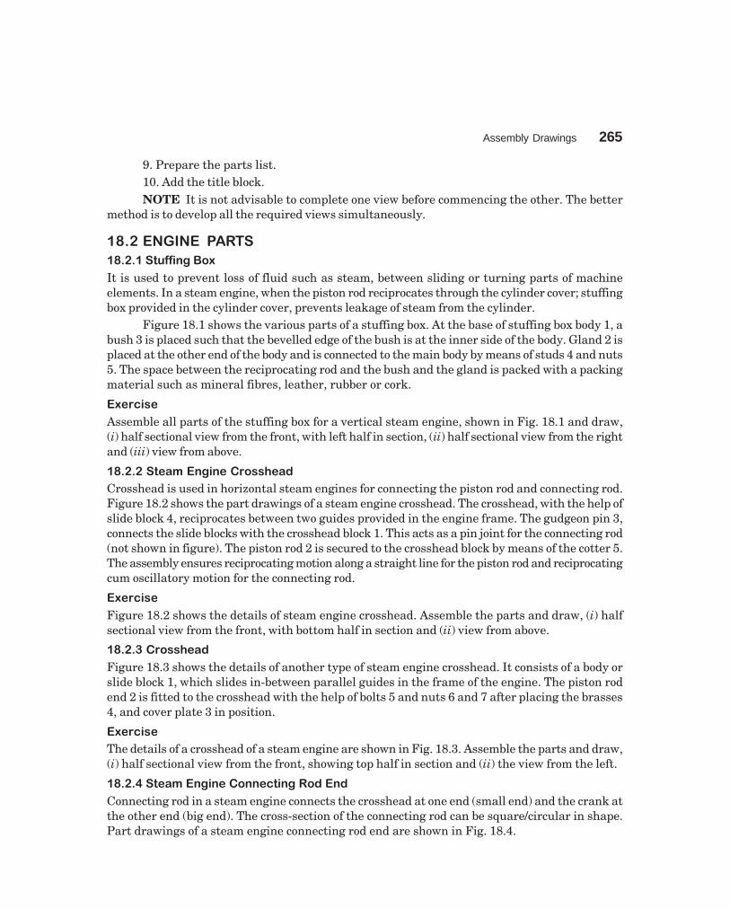
Assembly Drawings 265
dharmd:\N-Design\Des18-1.pm5
9. Prepare the parts list.10. Add the title block.NOTE It is not advisable to complete one view before commencing the other. The better
method is to develop all the required views simultaneously.
���� ������ �� �
�����������������
It is used to prevent loss of fluid such as steam, between sliding or turning parts of machineelements. In a steam engine, when the piston rod reciprocates through the cylinder cover; stuffingbox provided in the cylinder cover, prevents leakage of steam from the cylinder.
Figure 18.1 shows the various parts of a stuffing box. At the base of stuffing box body 1, abush 3 is placed such that the bevelled edge of the bush is at the inner side of the body. Gland 2 isplaced at the other end of the body and is connected to the main body by means of studs 4 and nuts5. The space between the reciprocating rod and the bush and the gland is packed with a packingmaterial such as mineral fibres, leather, rubber or cork.
��������
Assemble all parts of the stuffing box for a vertical steam engine, shown in Fig. 18.1 and draw,(i) half sectional view from the front, with left half in section, (ii) half sectional view from the rightand (iii) view from above.
�������������������������
Crosshead is used in horizontal steam engines for connecting the piston rod and connecting rod.Figure 18.2 shows the part drawings of a steam engine crosshead. The crosshead, with the help ofslide block 4, reciprocates between two guides provided in the engine frame. The gudgeon pin 3,connects the slide blocks with the crosshead block 1. This acts as a pin joint for the connecting rod(not shown in figure). The piston rod 2 is secured to the crosshead block by means of the cotter 5.The assembly ensures reciprocating motion along a straight line for the piston rod and reciprocatingcum oscillatory motion for the connecting rod.
��������
Figure 18.2 shows the details of steam engine crosshead. Assemble the parts and draw, (i) halfsectional view from the front, with bottom half in section and (ii) view from above.
����������������
Figure 18.3 shows the details of another type of steam engine crosshead. It consists of a body orslide block 1, which slides in-between parallel guides in the frame of the engine. The piston rodend 2 is fitted to the crosshead with the help of bolts 5 and nuts 6 and 7 after placing the brasses4, and cover plate 3 in position.
��������
The details of a crosshead of a steam engine are shown in Fig. 18.3. Assemble the parts and draw,(i) half sectional view from the front, showing top half in section and (ii) the view from the left.
�������� ��!��"#$"����""�% $"#�����"�
Connecting rod in a steam engine connects the crosshead at one end (small end) and the crank atthe other end (big end). The cross-section of the connecting rod can be square/circular in shape.Part drawings of a steam engine connecting rod end are shown in Fig. 18.4.

266 Machine Drawing
dharmd:\N-Design\Des18-1.pm5
12084
�42
15
�66
�33
5015
1
4
58
9015
M12
�24
5
R18
R75
M12
72
120
84
�50
R12
915
�24
15°
�42
45
2
�46
12
R18
R75
�13
72
�4215° 6
15
�24�33
3
Part No. Name Matl Qty
12345
BodyGlandBushStudNut, M12
CIBrassBrassMSMS
11122
Parts list
Fig. 18.1 Stuffing box

Assembly Drawings 267
dharmd:\N-Design\Des18-1.pm5
160
1:25
R30
�32
32 24 R5 R5 �50
R5
12
�62
�50
�25
7
R5R1070 22
1
�20 40 50 90 10
0
100�25
645R6
�50
7650
6 R6
10
�504
�25
R25
�32
100
(200
)
R25
�253
1:25
�25
.2
92
�20
.27
2 33 24
7
25
R23
90
1:25
5
Part No. Name Matl Qty
1
2
3
4
5
Block
Piston rod
Gudgeon pin
Slide block
Cotter
CS
MS
MS
Cl
MS
1
1
1
2
1
Parts list
Fig. 18.2 Steam engine crosshead
It consists of strap 3 which connects both the square end of the connecting rod 1 andthe brasses 2. The strap is fastened to the rod by jib 4 and cotter 5. Finally, the cotter islocked in position by the set-screw 6. Figure 19.3 shows the assembly drawing of a steamengine connecting rod end.
��������
The components of a steam engine connecting rod end are shown in Fig. 18.4. Assemble the partsand draw, (i) half sectional view from the front, with top half in section and (ii) view from above.
�����&����$"���"#$"����""�% $"#�����"�
Marine engines are used to produce high power and as such all the parts of the engine are sturdyand strong. The part drawings of a marine engine connecting rod end are shown in Fig. 18.5.
It consists of two halves of the bearing brasses 3, which are placed around the crank pin.The cover end 2 and the rod end 1 are placed in position and fastened by means of bolts 4 and nuts5, after placing the leather packing 8 in-between the bearing brasses. Snug 7 in the bolts, preventsrotation of the bolts while they are tightened with the nuts. Split cotters 6 are used to prevent theloosening tendency of the nuts. Figure 19.2 shows the assembly drawing.

268M
achine Draw
ing
dharmd:\N
-Design\D
es18-1.pm5
Fig. 18.3 Crosshead
�28
�50 48 130
190
6
322
R
76S
NU
G,3
×3
�28R
76
45° 156
112
28
48
6
R
37
72 130
190
190
130
90 56
32
�28R
76
3
R42
204
7688
R36
440
46
210
6 7
28 20
M28M
28
655SNUG,3 × 3
�44
22
Sl. No. Name Matl Qty
1234567
BodyRod endCover plateBrassesBoltNutLock nut
ClMSMS
Brass———
1111222
Parts list
R R
f60
3
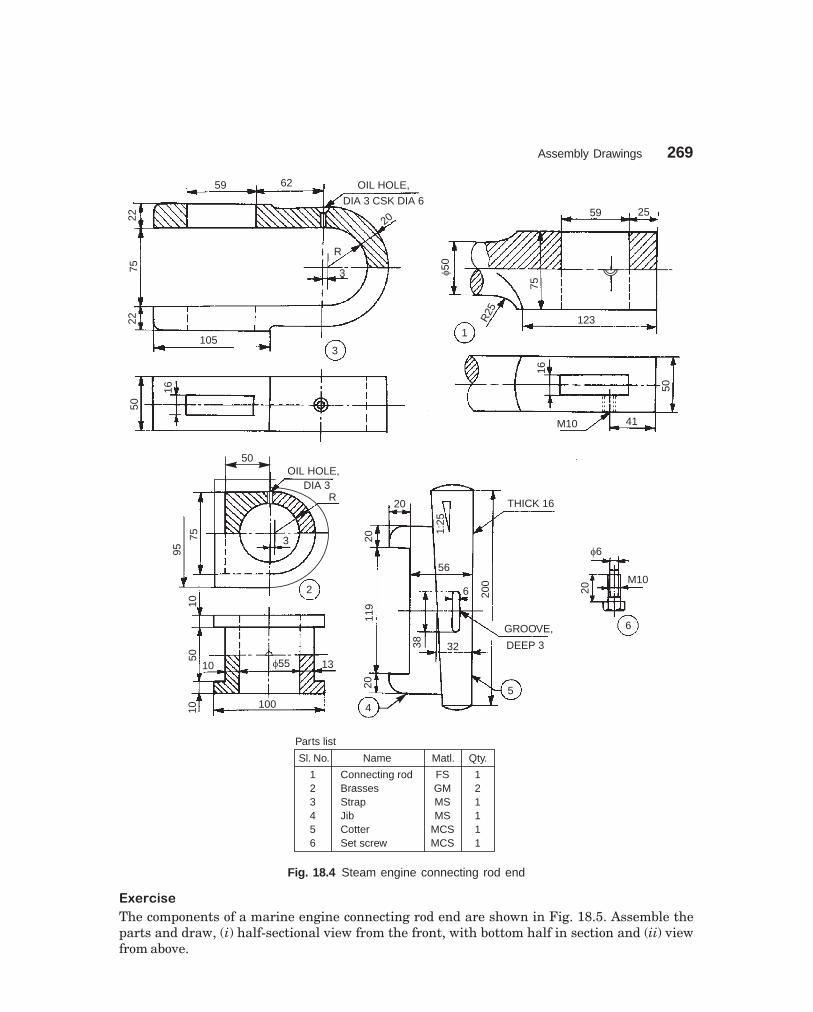
Assembly Drawings 269
dharmd:\N-Design\Des18-1.pm5
59 62
2275
22
OIL HOLE,
DIA 3 CSK DIA 6
20
R
3
1053
16
50
59 25
�50
1
R25
75
123
16
M10 41
50
50OIL HOLE,
DIA 3R
75
95
3
2
1050
10 �55 13
10 100
20
20
1:25
THICK 16
56
200
6
119
38 32
GROOVE,
DEEP 3
520
4
�6
M1020
6
Sl. No. Name Matl. Qty.
123456
Connecting rodBrassesStrapJibCotterSet screw
FSGMMSMS
MCSMCS
121111
Parts list
Fig. 18.4 Steam engine connecting rod end
�'��%$��
The components of a marine engine connecting rod end are shown in Fig. 18.5. Assemble theparts and draw, (i) half-sectional view from the front, with bottom half in section and (ii) viewfrom above.

270 Machine Drawing
dharmd:\N-Design\Des18-1.pm5
�����(�)$� �"
A piston is cylindrical in form and reciprocates in a cylinder. The petrol engine piston is generallydie cast in aluminium alloy. It is connected to the small end of the connecting rod by means of agudgeon pin. Figure 18.6 shows the details of the petrol engine piston assembly.
50 R142
�48
50SPOT
FACING
11
46�80
R30
1
190
16 12
�48
9
4620
R56
9 3
R13
0
R14
228
4
190
46
11
�48
X
9
12
2
18
90
90
18
�48 76 11
8
18
X–X
12
90
5076R24
15M12 R62
12
21 R80
7 8
R15
0
118
15 80
6
�40
M12 DEEP 12
�48
36 36 270
5 4
36
�72
80
X
Sl. No. Name Matl. Qty.
12345678
Rod endCover endBearing brassBoltNutSplit cotterSnugLeather packing
FSFSGMMSMSMSMS—
11222222
Parts list
Fig. 18.5 Marine engine connecting rod end

Assembly Drawings 271
dharmd:\N-Design\Des18-1.pm5
Five piston rings 4 are positioned in the piston 1; four at the top and one at the bottom. Thetop piston rings, known as compression rings, prevent leakage of gases from combustion chamberinto the crank case. The bottom one; oil or scraper ring, prevents the lubricating oil from enteringthe combustion chamber.
The piston is connected to the small end of the connecting rod, by means of the gudgeon orpiston pin 2; the axial movement of which is prevented by piston plugs 3.��������
Assemble the parts of the piston, shown in Fig. 18.6 and draw the following views:(i) Sectional view from the front,
(ii) Half sectional view from the left, and(iii) Sectional view from above.
50
32
72 63
R6
4
27
R19
0 R6�74�85�92
1518
129
25°10
2215
3415
1
10°2.5
�73
�30
�22 �78
4777
2 × 45°
�11
15
�22
12
3
45° 3
3
�85
�93 4
�22
�11
2
88
No. Name Matl Qty
1234
PistonPiston pinPiston pin plugPiston ring
Al-alloyHCSHCS
Cl
1125
Parts list
7
Fig. 18.6 Piston of a petrol engine
�����!�� ��"��������#$�����#"%
Radial engines are mainly used for aircraft applications and are air-cooled type. The radial engineemploys a master connecting rod to which other connecting (articulated) rods are attached radially.

272M
achine Draw
ing
dharmd:\N
-Design\D
es18-1.pm5
Fig. 18.7 Radial engine sub-assembly
18
�24
�35
R20
26
222 18
014
414
36
R724 Holes,Dia 12
26
43 43 1
42�3
15
R6
5
20
9 24 970
50
R6
32
72 68
5
R6
R6
189
�74�85�92
3
1518
129
10
2234
715
15
0.3
45°
�85
310
�93
�74
2.5
�30
�22
10°
�76
4777
2 × 45°
�11
15
�22
12
9
�52
�46
70
4
�24
�22
42
5
50
�15 �9
�12
43 57
�2
�11
877
�22
�12 �15
624
26
180
130
�24
�35
R24
5
18
2
�15 �24
42�3
R6
18
5
24
Part No. Name Matl Qty
1
2
3
4
5
6
7
8
9
10
Master rod
Articulated rod
Piston
Master rod bearing
Rod bush-upper
Rod bush-lower
Link pin
Piston pin
Piston pin plug
Piston ring
MCS
MCS
Al
Cd-Ag
Babbit
Babbit
HCS
Ni-Cr steel
MS
CS
1
4
5
1
5
4
4
5
10
25
Parts list
27R78
R54
R13
f63
f52
26
R189

Assembly Drawings 273
dharmd:\N-Design\Des18-1.pm5
Figure 18.7 shows the radial engine sub-assembly of a five cylinder engine. The articulatedrods 2 are connected to the master rod 1 by means of rod bush 6, and link pins 7. Aluminiumpistons 3 are assembled with master and articulated rods using bushes 5, piston pins 8 and pistonpin plugs 9. Five piston rings 10 are provided per piston. The bearing 4 is used at the big end ofthe master rod; the end of which is connected to the crank pin of the crankshaft.
��������
Prepare an assembly drawing of the radial engine sub-assembly, the details of which are shownin Fig. 18.7, showing one piston in full section.
���������������
It is used to provide a short reciprocating motion, actuated by the rotation of a shaft. Eccentricsare used for operating steam valves, small pump plungers, shaking screens, etc. The componentsof an eccentric are shown in isometric views (Fig. 18.8a) for easy understanding of their shapes.Rotary motion can be converted into a reciprocating motion with an eccentric, but the reverseconversion is not possible due to excessive friction between the sheave and the strap. The crankarrangement, in a slider crank mechanism however, allows conversion in either direction.
Packing
Straps
Sheave
Fig. 18.8a Components of an eccentric in isometric view
Figure 18.8b shows the various parts of an eccentric. The sheave 2 which is in the form ofa circular disc with a stepped rim is keyed on the shaft. When the shaft rotates, the sheaverotates eccentrically because of the eccentrically placed hole in it and imparts reciprocating motionto eccentric rod 6.
The straps 1 are semi-circular elements with an annular recess to accommodate the steppedrim of the sheave. These are held together on the sheave by means of strap bolts 4, with packingstrips 3 placed between them. The eccentric rod is fixed to the eccentric strap by means of thestuds and nuts 5.
��������
The details of an eccentric are shown in Fig. 18.8b. Assemble the parts and draw, (i) half sectionalview from the front, with top half in section, (ii) view from the right and (iii) view from above.
�����&�����%������'
It is used to supply lubricating oil from the sump to the required places of an internal combustionengine, under pressure and is positive displacement type. Figure 18.9 shows the details of arotary gear pump.

274 Machine Drawing
dharmd:\N-Design\Des18-1.pm5
Fig
. 18
.8b
Det
ails
of
an e
ccen
tric
R16
LIN
EA
R,
4T
HIC
K
22
6
�17 45
R20
95140
�32
20
�18
12
R10
510
30
16
R6
R6 20
KE
YW
AY,
20×
7
18
R6532
�8016
2
�200�190
45 25
R6
20
65
X60
60
M16
×1.
5
DE
EP
25
140
95
R12
125
X
�190 �2
00
1
X–X
45
26
280230
�16
M16
8
SP
LIT
PIN
DIA
3,LO
NG
30
�12
832
22M16
70 5
55
�16
4
164
�25 12
45
25
45
5
258
3
Par
tNo.
Nam
eM
atl
Qty
1 2 3 4 5 6
Str
aps
She
ave
Pac
king
strip
Str
apbo
ltS
tud
with
nut
Ecc
entr
icro
d
Cl
Cl
Leat
her
MS
MS
For
ged
stee
l
2 1 2 2 2 1
Par
tslis
t
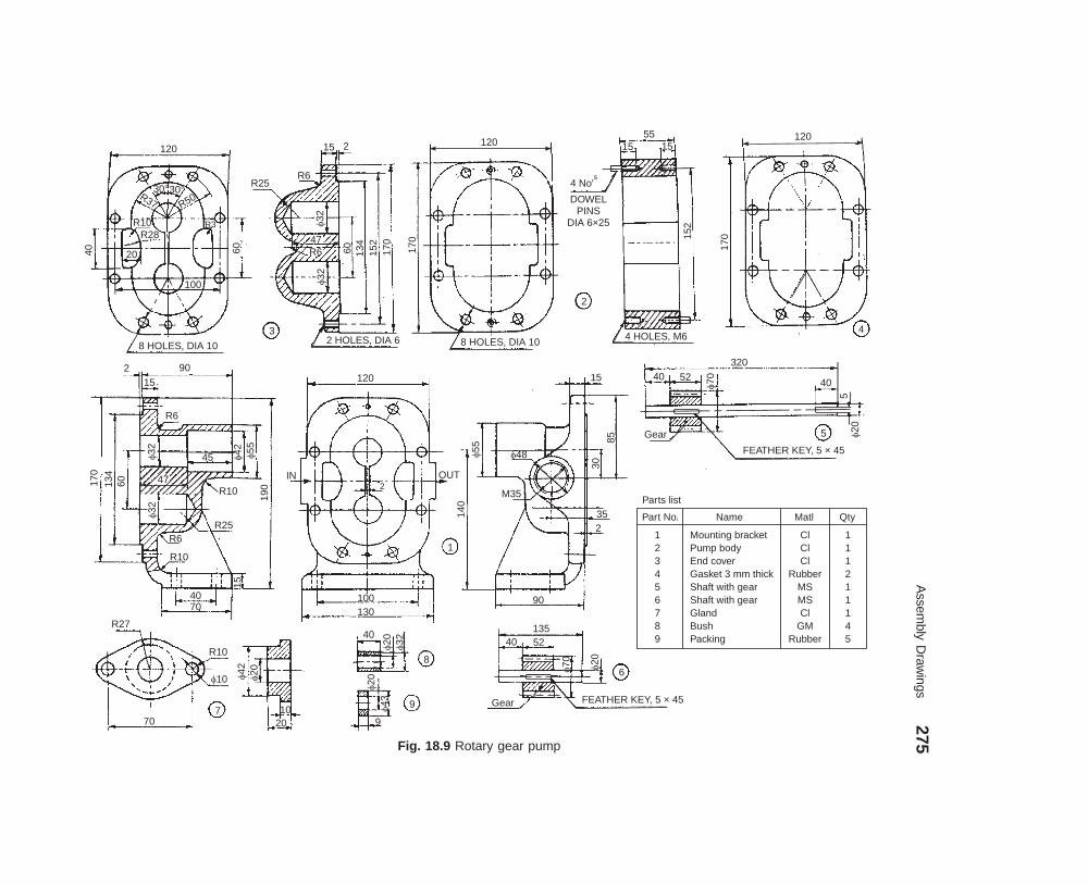
Assem
bly Draw
ings275
dharmd:\N
-Design\D
es18-1.pm5
Fig. 18.9 Rotary gear pump
120
30°30°
R50R37
R10R28
R36040 20
100
8 HOLES, DIA 10
3
R25R6
15 2
�32
47R6
�32
60 134
152
170
170
120
2 HOLES, DIA 6 8 HOLES, DIA 10
4 No's
DOWELPINS
DIA 6×25
5515 15
152
2
4 HOLES, M6
120
170
4
902
R6
45�32
170
134
60 47
�32
R10
R25R6
R10
15
4070
190
IN
120
OUT2
100130
1
140
�55
�48
M35
30
85
15
352
90
32040 52
�70
Gear
40
5�205
FEATHER KEY, 5 × 45
R27
70
R10
�10
7
�42
�20
1020
40
�20
�32
�20
�43
9
9
8
13540 52
�70 �20
Gear FEATHER KEY, 5 × 45
6
Part No. Name Matl Qty
123456789
Mounting bracketPump bodyEnd coverGasket 3 mm thickShaft with gearShaft with gearGlandBushPacking
ClClCl
RubberMSMSCl
GMRubber
111211145
Parts list
15
�42 �55

276 Machine Drawing
dharmd:\N-Design\Des18-1.pm5
The two gaskets 4 are placed; one on the end cover 3 and the other on the mounting bracket1 in position. Two each of bushes 8 are placed on the end cover and mounting bracket to providebearing surfaces for the gear shafts. End cover is connected to the pump body 2 after placing thedowel pins in the body. The shaft with gear 6 is placed in the bottom recess, whereas the shaftwith gear 5 is located in the top recess of the end cover and pump body assembly. Finally, themounting bracket is connected to the pump body after locating the dowels in the pump body. Thegland 7 is placed on the mounting bracket, after locating the packing 9 between the mountingbracket and the shaft with gear 5.
The end cover, pump body and the mounting bracket are connected or fastened, using boltsand nuts (not shown). Similarly, the gland is fastened to the mounting bracket by using two studsand nuts (not shown). At the end, oil inlet and outlet connections are made through the mountingbracket.��������
Assemble the parts of the rotary gear pump, shown in Fig. 18.9 and draw, (i) sectional view fromthe front and (ii) view from the right.������(���)�"*�
Air valve is used with a diesel engine to let-in air into the cylinder. Normally, the valve is inclosed position under spring pressure. It is opened by means of a cam, actuating the rocker armthrough a lever.
Figure 18.10 shows the details of an air valve. The valve 2 is introduced through the valvebox 1 so that it fits into the valve seat. The spring 3 is slipped through the stem of the valve andmade to sit at S-S in the box. The spring seat 4 is then placed on the valve and fixed in position bymeans of a hexagonal nut 5 with pin. The rocker arm 6 is fitted to the valve box at M by means ofthe pin 7. The lever 8 is placed in the rocker arm at N and positioned by pin 9.��������
Figure 18.10 shows the complete details of air valve of a diesel engine. Assemble the parts anddraw, (i) sectional view from the front and (ii) view from above. Use suitable scale.�������+��"��,�����
The fuel injector is used on a diesel engine. It injects highly pressurised diesel, supplied by a fuelpump, into the combustion chamber of the engine cylinder.
The details of the fuel injector are shown in Fig. 18.11. The spring 7 is located in the body 1above the distance piece 6. The nozzle pin 5 is placed inside the nozzle 2 and attached to the body bymeans of nozzle holder 3. The screw adjuster 8 is placed over the spring from the other side (top) ofthe body. The adjusting screw 9 is located in the cap 4 and it is held in position by the lock-nut 10.
The body has a narrow hole of 2 mm diameter, through which the pressurised diesel fromthe fuel pump enters the nozzle. When it exceeds the set pressure of the spring, the diesel issprayed through the nozzle into the cylinder and as soon as the pressure falls back, the injectionceases. The excess oil left-over in the injector, flows back through the clearance around the distancepiece into the over-flow exit, provided at location M6.��������
Figure 18.11 shows the details of a fuel injector. Assemble the parts and draw, (i) half sectionalview from the front and (ii) the view from above.���������$"#*��)*� ���*+ %�
A clutch is a device through which power is transmitted from the engine or driving shaft to thedriven shaft. Facility for disengaging the connection and stopping the power transmission as andwhen required is incorporated in all designs of clutches.

Assem
bly Draw
ings277
dharmd:\N
-Design\D
es18-1.pm5
Fig. 18.10 Air valve
2 HOLES, M15
R20
118
135
100
12
40
�25 M
90
253
�38
�43R35
33
�35
6
50
S S
18
�70�20
�110
�40
�110�125212
610
611
0
159 25
165
50
150
140
R35
3 WEBS,
12 THICK R84175
R73
15
8 2150
21
HOLE, DIA. 25
1
HOLE, DIA 21
�564
1113 �20
�40
�40 5
�5
118
�503
M20
2
�20300
15
8
�100
�1186
9
�18
38
�15
15
45°83
Oil hole118
R30R25
28
28
40 45 20
�18N
1616
15
6
18
�25�50
1515
20
DIA15
�25
73
�21
M15
1821
DIA 40×20 THICK �18
M3
�14
8�30
68
43
Part No. Name Material Qty
123456789
Valve boxValveSpringSpring seatHexnut M20 with pinRocker armPinLeverPin
ClFS
SPSMSMSFSMSMSMS
111111111
Parts list
R2530
� 60

278M
achine Draw
ing
dharmd:\N
-Design\D
es18-1.pm5
Fig. 18.11 Fuel injector
M22
M6
10
10
M14 �2
1032
10 1416
13 �16
145
�25
�2
2
4421 23
�6M 20×1
1R10
14
32 50
�11
�25M20
�20
�14�21
1623
2933
3
23
M8
10
517 15
M8
9
�6 3
8�14
�10
3
�2.5
25
7
�14 3
�5.5
79
6
3�3.5
�3.5
�6 2819
90°
5
�16�6�2
�1423
2029
�1
2120°
�1.5 4
17
M8
7
3025
�16
M22
Sl No. Name Matl Qty
1234567
89
10
BodyNozzleNozzle holderCapNozzle pinDistance pieceSpring
Screw adjusterAdjusting screwLock nut
ClBrassMSMS
BrassMS
SpringsteelMSMSMS
1111111
111
Parts list
4
90°
Assembly Drawings 279
dharmd:\N-Design\Des18-1.pm5
Friction clutches which are in common use are of two categories—single plate/disc andmultiplate/disc clutches. In a single plate clutch, only one plate with one or two friction surfacesis used. Figure 18.12a illustrates various parts of a single plate clutch. It consists of a flywheel 1which provides one friction face. The flywheel is mounted on the driving shaft. The spring loadedfriction plate 2 is mounted on the driven splined shaft 11. The clutch pressure plate 3 is connectedto the cover 13 through clutch release levers 4, lever plate 5, lever fulcrum pin 6, by lever screw7 and nut 8.
The driving flange 10 houses lever spring 9 along with the clutch pressure plate. The coveris bolted to the flywheel by means of screws 14. The friction facings are riveted to the segments ofthe spring loaded friction plate to give smooth engagement and prevent sticking.
When the clutch is engaged, the friction plate is sandwitched between the faces of theflywheel and the pressure plate, thus transmitting power to the driven shaft through the frictionplate.
When disengaging, the clutch springs 12 act through the release levers and force thepressure plate away from the friction plate, thus disengaging the driven shaft. Figure 18.12bshows an isometric view of the assembly drawing of the single plate clutch.
��������
Figure 18.12 a illustrates the details of a single plate clutch. Assemble the parts and draw, (i) theview from the front and (ii) sectional view from the right.
������-.�"��'"���+��������"����
In a multiplate friction clutch, a number of discs or plates with frictional surfaces on either sideare located alternately on the driving and driven shafts. By bringing these, close together byexternal pressure, power can be transmitted from the driving to the driven shaft. Multiplateclutches are normally wet type, whereas, single plate clutches are dry. The multiplate clutch islocated on the driving shaft. The pulley/wheel mounted on the shell serves as a driven member.There is no driven shaft.
Figure 18.13a illustrates various parts of a multiplate clutch. The serrations on the internaldiameter of the shell 1, receive the alternate friction discs called the outside plates 3. The shellalong with a bush is mounted freely on the driving shaft, has provision to receive the drivenpulley or wheel. A centre boss 5 is keyed onto the driving shaft. The serrations on the centre bossreceive the alternate friction discs called the inside plates 4.
The front cover 2, is fixed to the shell by means of six small set screws 12. The front coveris able to either slide or rotate freely on the driving shaft with the bush provided. The slidingsleeve 9, rotates freely on the driving shaft and is connected to the front cover through three jawlevers 7, and three L-levers 8. The last outside plate called a stud carrier 6, is provided with thearrangement to carry three studs 10, which are operated by the sliding sleeve through theL-lever.
The sliding sleeve rotates with the clutch body, i.e., the shell. The sleeve can be movedforward by an operating lever (not shown) in order to exert pressure on the studs. The plates willthen get pressed together and the drive is completed. Figure 18.13b shows the assembly drawingof the multiplate clutch.
��������
Assemble all parts of the multiplate friction clutch shown in Fig. 18.13 (a) and draw, (i) the halfsectional view from the front, with top half in section and (ii) the view from the right.

280M
achine Draw
ing
dharmd:\N
-Design\D
es18-1.pm5
Fig. 18.12 Single plate clutch (contd.)
6 HOLES, M8
�100
2 DOWEL PINS,DIA 6
1
5
12
�29
7�26
4�20
0�12
0 �15
10
�40 �80
�22
0
4 SCREWS,
M106
108 TEETH2.75 MODULE
6 1832
3 HOLES, DIA 6 26
�26 6 SPRING
LOCATORS,DIA 12
HEIGHT 5
25
�126
3
�18
6
40
1010
6 6
14
18 RIVETS, DIA 9�126 PCD 156
40°
27°
�116 6 SPRINGS,
DIA 15×DIA 3
9
2
10S
PLI
NE
S
DIA
20×
DIA
25
18
�30
�44 �18
6
34
1
6 HOLES,DIA 15
3H
OLE
S,D
IA12
R70R70
R60
R76
R76
R20
3 SLOTS, 35×26
2 HOLESDIA 7
13
3 HOLES,DIA 25
�24
0
15
�86
60
48
�3
7
�23�23
12
6 HOLES,DIA 9
4

Assembly Drawings 281
dharmd:\N-Design\Des18-1.pm5
Fig. 18.12 Single plate clutch
3225
3
258
18
65
4
6
14
18
�6
3
155
0.5
16 10
4
9
10
10
610
�30
�30
20
R35 29
2536
7
15
14
5
7
5
�1.
5
�8
10
26
�6
45
6
7
14�6
1018
M8
�124
12
8
M8
11
HERRING-BONE, 24TEETH×2.5MODULE
10 10�60
�54
�38 �33
�38
26 18 75 60
215
�15
10S
PLI
NE
S,
DIA
20×
25
9(a)
4
2
3
1
9
14 12
(b)
13
5
7
8
10
11
Sl. No. Name Matl Qty
123456789
1011121314
Flywheel with driving shaftSpring loaded friction plateClutch pressure plateClutch release leversLever plateLever fulcrum pinLever screwNutLever springDriving flangeDriven shaftClutch springCoverHexagonal headed screws, M8
FS—FSMSMSMSMS—
Sp.SFSFS
Sp.SMS—
11133333311616
Parts list
4 5 3
XX – X
X

282M
achine Draw
ing
dharmd:\N
-Design\D
es18-1.pm5
Fig. 18.13a Details of multiplate friction clutch (contd.)
6 HOLES, M12 DEEP 18
EQUI-SP PCD 462
6 SLOTS, WIDE
120 EQUI-SP
�462
�432
30°
OIL HOLE,DIA 6 K
EY
WAY
,
200
24
216
87
15
96
8
�84
�18
4�10
0�29
4
Oil
groo
ve
�11
4
54
�84
5
�21
0�18
0
84
90
KE
Y,8×
8�26
4
6 HOLES, DIA 12
EQUI-SP PCD 482
3 HOLES, DIA 50
EQUI-SP PCD 363
�492
�240
21 24 21
Oil hole
30°
�992
213
4522.5
�17
248
�43
2
146
105Oil groove
20
24
6
933
M24
�48
�46
0�28
0
3B
OS
SE
SE
QU
I-S
PP
CD
363
120 PLATES FILED
TO SLIDE INTOOUTERCASING
324
�429
�432 �45
9
�27
9
INSIDE PLATES TO SLIDEOVER CENTRE BOSS
54 4
�270
�213
�41
79 8
18R15
50
R15
32
30
�17
�42�42�17
8
1
24
8×
4
9
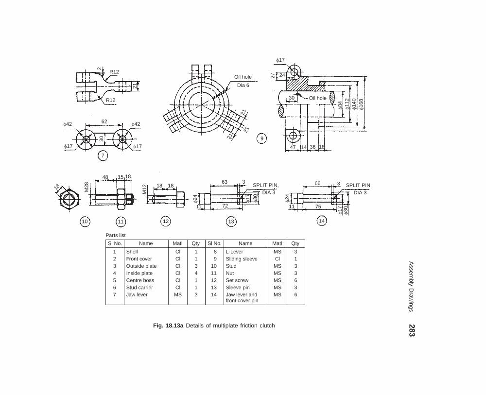
Assem
bly Draw
ings283
dharmd:\N
-Design\D
es18-1.pm5
Fig. 18.13a Details of multiplate friction clutch
2
R12
R12
21
�42 �42
�17�17
30
7
62
Oil hole
Dia 6
21
2121
9
�17
27 24
30 Oil hole
�84
�11
2�14
0�16
8
47 14 36 18
18 M28
48 15 18
10 11 12 13 14
M12 18 18
�24
63
72
3SPLIT PIN,
DIA 3
�17
�30
�24
11
66
75
3 SPLIT PIN,DIA 3
�17
�30
Sl No. Name Matl Qty
1234567
ShellFront coverOutside plateInside plateCentre bossStud carrierJaw lever
ClClClClClCl
MS
1134113
Sl No. Name Matl Qty
89
1011121314
L-LeverSliding sleeveStudNutSet screwSleeve pinJaw lever andfront cover pin
MS
MSMSMS
Cl
MSMS
3133636
Parts list
11
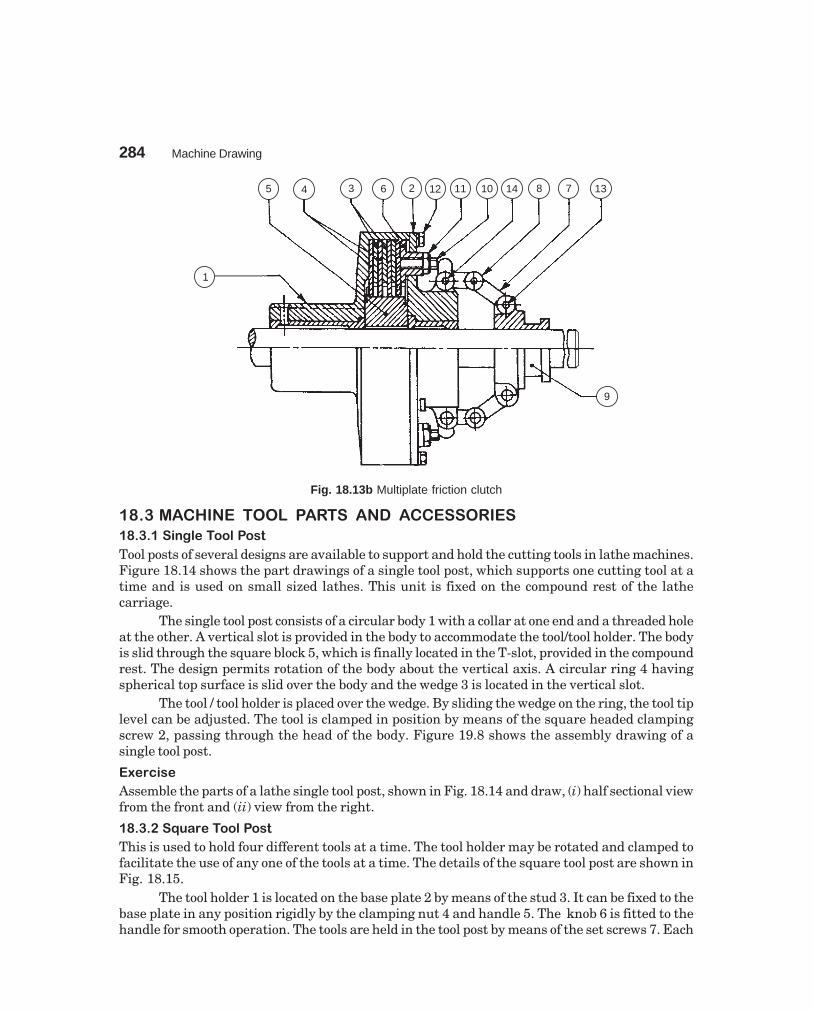
284 Machine Drawing
dharmd:\N-Design\Des18-1.pm5
13781410111226345
1
9
Fig. 18.13b Multiplate friction clutch
���� ���,� �� ����� )���� � � ����������
���-������"� ��"���
Tool posts of several designs are available to support and hold the cutting tools in lathe machines.Figure 18.14 shows the part drawings of a single tool post, which supports one cutting tool at atime and is used on small sized lathes. This unit is fixed on the compound rest of the lathecarriage.
The single tool post consists of a circular body 1 with a collar at one end and a threaded holeat the other. A vertical slot is provided in the body to accommodate the tool/tool holder. The bodyis slid through the square block 5, which is finally located in the T-slot, provided in the compoundrest. The design permits rotation of the body about the vertical axis. A circular ring 4 havingspherical top surface is slid over the body and the wedge 3 is located in the vertical slot.
The tool / tool holder is placed over the wedge. By sliding the wedge on the ring, the tool tiplevel can be adjusted. The tool is clamped in position by means of the square headed clampingscrew 2, passing through the head of the body. Figure 19.8 shows the assembly drawing of asingle tool post.
��������
Assemble the parts of a lathe single tool post, shown in Fig. 18.14 and draw, (i) half sectional viewfrom the front and (ii) view from the right.
���-���/���� ��"���
This is used to hold four different tools at a time. The tool holder may be rotated and clamped tofacilitate the use of any one of the tools at a time. The details of the square tool post are shown inFig. 18.15.
The tool holder 1 is located on the base plate 2 by means of the stud 3. It can be fixed to thebase plate in any position rigidly by the clamping nut 4 and handle 5. The knob 6 is fitted to thehandle for smooth operation. The tools are held in the tool post by means of the set screws 7. Each
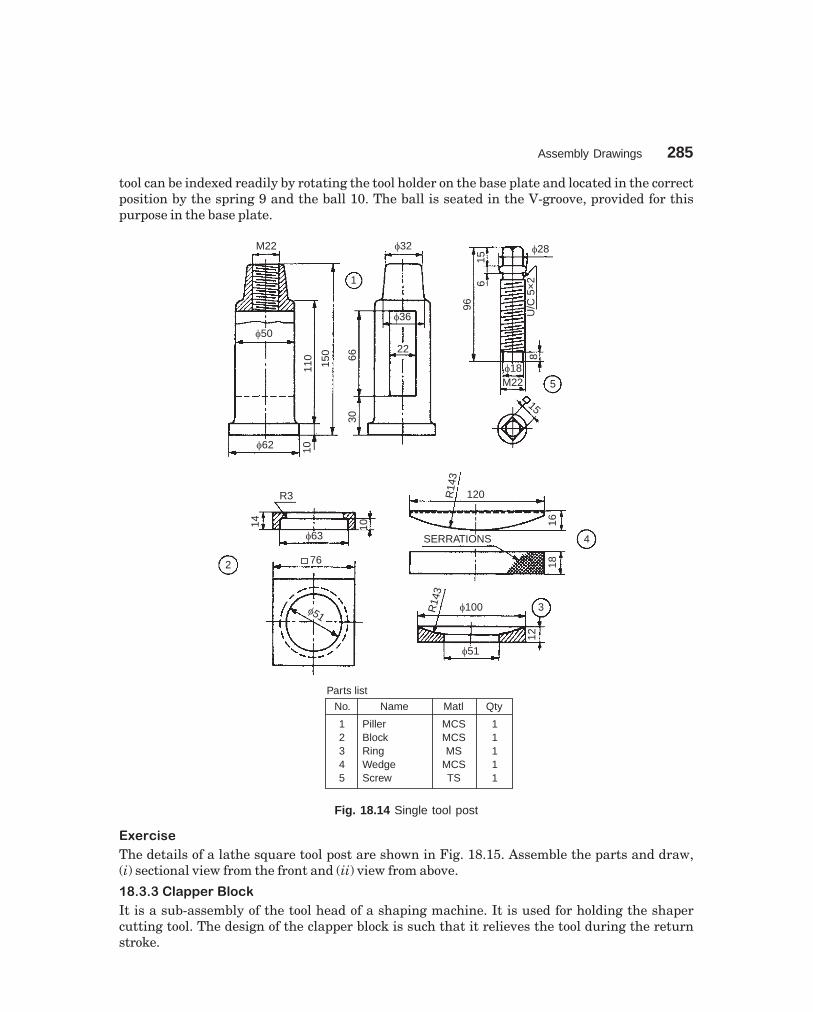
Assembly Drawings 285
dharmd:\N-Design\Des18-1.pm5
tool can be indexed readily by rotating the tool holder on the base plate and located in the correctposition by the spring 9 and the ball 10. The ball is seated in the V-groove, provided for thispurpose in the base plate.
M22
�50
�62 1011
0
150
3066
1
�32
�36
22
966
15
�28
U/C
5×2
8
�18M22 5
15
R3
14
2
�63
10
76
�51
R14
3
120
16SERRATIONS 4
18
R14
3
�100
�51
12
3
No. Name Matl Qty
12345
PillerBlockRingWedgeScrew
MCSMCSMS
MCSTS
11111
Parts list
Fig. 18.14 Single tool post
��������
The details of a lathe square tool post are shown in Fig. 18.15. Assemble the parts and draw,(i) sectional view from the front and (ii) view from above.
���-�-�"�''���"��0
It is a sub-assembly of the tool head of a shaping machine. It is used for holding the shapercutting tool. The design of the clapper block is such that it relieves the tool during the returnstroke.

286M
achine Draw
ing
dharmd:\N
-Design\D
es18-1.pm5
Fig. 18.15 Square tool post
X–X150
�2680
102
�60 45°52
�1016 20
40 901
934 17
�28Y–Y
�60
M25150
�17
90°�10 �46
M25
M10,DEEP 10
R8
46
SR50
4
�62
1026
46
M10
95115
5S 40�
38
6M10,Deep 10�7
4.5
30
�2
�25
122
4
25 32
M16
87
22
14
7556
7
M16
�109
2 PCD 104
150
8 HOLES, M16
60
X
160
M25
60303
Part No. Name Matl Qty
123456789
10
Tool holderBase plateStudClamping nutHandleKnobSet screwGrub screwSpringBall 9�
MSMSMSMSMS
EboniteMSMS
SteelMS
1111118411
Parts list
3

Assembly Drawings 287
dharmd:\N-Design\Des18-2.pm5
Figure 18.16 shows the details of a clapper block. This consists of a swivel plate 1, attachedto the vertical slide of the tool head (Fig. 18.17) of the shaping machine. The drag release plate 2relieves the tool during the return stroke. The drag release plate carries the tool holder 4 and thetool is fixed in it by means of the tool clamping screw 5. The washer 6 is used over the drag releaseplate for providing even bearing surface to the tool.
70
R108
141
16 1665
R108
8476
31
16
15 15
13
�13
�30 �
21 12 6
18
30 45
�42
R9
12 69 24
M14
�24
�30
4
�30
�60
6
M14 20
6 50 25
5
100
�13
315 15
13
�13
84
�42
12 18 �30
42
R108
632
Part No. Name Matl Qty
123456
Swivel plateDrag release platePinTool holderTool clamping screwWasher
ClClMS
MCSMSMS
111111
Parts list
1
9
Fig. 18.16 Clapper block
��������
Figure 18.16 shows the details of a shaper clapper block. Assemble the parts and draw, (i) theview from the front and (ii) sectional view from the left.
��� ������ ���� ���� �����
The shaper tool is fixed to the tool head through a tool holder and a clapper block. Figure 18.17shows the details of a shaper tool head slide. The back plate 2 is attached to the front face of the

288M
achine Draw
ing
dharmd:\N
-Design\D
es18-2.pm5
Fig. 18.17 Shaper tool head slide
24
�15
18
3
M13
18 2
7631
M18
135
1
2246
4646
4610
SQ THD,
DIA15×3
�37
37
�140
27102
2
�93
�20
12
25°
18
2121
M9
1120 20
�12�21
2624
�24
�15
5
486
6
SQ
TH
D,D
ia15
×3
3
�37
153
2112 6
M18
�30
36
R108
96
33 33
34 27
18 305 6
M6
40
M13
�33 15
6 645 18 7
�24
�12
20�18
S 33� 42 51S 29�
M9
�12
4
R27
�18�9 78
�24
R27
Part No. Name Matl Qty
Parts list
1234567
Vertical slideBack plateScrewHandleSleeveSwivel pinSwivel plateclamping screw
ClCl
MSMSMSMSMS
1111111
66216

Assembly Drawings 289
dharmd:\N-Design\Des18-2.pm5
reciprocating ram of the shaper. The vertical slide 1 is fitted to the back plate through the guide-ways and it is positioned on the screw 3 by means of sleeve 5 and the handle 4. When the screw isoperated, the vertical slide moves along with the screw. As the slide is rigidly fixed to the screwand permitted to slip, when the screw is rotated, the slide is restricted to have only reciprocatingmovement. By rotating the back plate about a horizontal axis, the slide can be made to traverse atany desired angle to the vertical, for shaping inclined surfaces. The swivel plate (Fig. 18.16) ispivoted to the slide by the swivel pin 6 and clamped at the desired position by the clampingscrew 7.
��������
The details of a shaper tool head slide are shown in Fig. 18.17. Using a suitable scale, draw,(i) view from the front and (ii) sectional view from the right.
��� ����� ����������
It is a part of a lathe machine and is used to support lengthy jobs. To accommodate works ofdifferent lengths between centres, the tail-stock may be moved on the lathe bed to the requiredposition and clamped by means of a clamping bolt.
Figure 18.18 shows various parts of a tail-stock. The barrel 2 is fitted into the bore of thetail-stock body 1 and is prevented from rotation by the feather key 9 placed underneath of it. Thebarrel has a threaded portion at its end and the spindle 3 is inserted into the barrel through this.The hand wheel 6 is mounted on the spindle by a key and is retained in position by a nut. Thespindle bearing 5 is placed between the hand wheel and the tail-stock body. A tapered hole providedat the front end of the barrel, receives the dead centre 4 or a tapered shank of the drill or reamer.
When the hand wheel is operated, the barrel is made to move in or out of the tail-stockbody. In the required position of the barrel, clamping may be made by means of the clampinglever 7 and stud 8 which is fitted to the tail-stock body. The spindle bearing is fixed to the body bymeans of the screws 10.
��������
Figure 18.18 shows the details of a lathe tail-stock. Assemble the parts and draw to a suitablescale, (i) sectional view from the front and (ii) view from the left.
��� ������� ������� ����������
Jobs requiring milling operations in relation to their axes of rotation, are usually supportedbetween the centres of the dividing head and adjustable centre provided in the tail-stock. Theparts of a milling machine tail-stock are shown in Fig. 18.19. This is similar to the lathe tail-stock.
The screw 4 is introduced into the threaded hole of body 1. Centre 2 is inserted into thebody such that, the hole provided in it enters onto the screw 4. Hand wheel 3 is mounted on thescrew 4, by using the key 8 and fixed in position by using washer 6 and nut 7.
By operating the hand wheel, the centre can be given the required movement/fineadjustment, while clamping the job between the centres. After adjustment, the centre can belocked by the screw 5, which is introduced into the body, prior to the location of the centre in thebody. Figure 19.11 shows the assembly drawing.
��������
Assemble the parts of the milling machine tail-stock, shown in Fig. 18.19 and draw, (i) sectionalview from the front and (ii) view from the right.

290M
achine Draw
ing
dharmd:\N
-Design\D
es18-2.pm5
Fig. 18.18 Lathe tail-stock
215
12�36
�60
144
36
35
�6
24 18
22
R9
72
� 42
R15 R15120
18
R18
5
84
R940
14
216
3 39
�68
�78
PCD 52
24
�12
1414
3
R21R96R96
R27
R18
M12
30 12 30 7245 R9R9
R
R936
�18
60°
24
636512 1218
90°
3
8 1.5
M6
�36 �18
�31
10
5
26M12×18
4 HOLES,
DIA 6, PCD 52
12
60
�18
30°7
�12
�18
�24
�21
�42
24
�31
9
6
24�15
�168
18
KEYWAY,4 × 2
48 1621:20
�36 �18
18 FEATHER WAY, 4×3
2
36
�24
SQ Thd Dia 21×3 LH
12
3
�6
104
M13
2045
158
9
SQ THD, DIA 21×3 LH
162
3
6 26 24 14 1.5 12
�26
M12
�15�24
KEY WAY, 4×2
M121:20
60°
�18
27 51
4
�18
Part No. Name Matl Qty
123456789
10
BodyBarrelSpindle with washer & nutCentreSpindle bearingHand wheelClamping leverStudFeather keyScrew
ClMSMSCSCICIMSMSMSMS
1111111114
Parts list
15
R241
R40
R40
6
4 HOLES, M6 DEEP 9

Assembly Drawings 291
dharmd:\N-Design\Des18-2.pm5
32R30
35 M12
R15
18125
25
�40
30150
610 1
10036
�30
M15
18R12
5
�18150
KEYWAY,5 × 2.5
18
�80
�28 �15
335
3
32
M12
63 18
5
35
�15 R15
60°
180
�30
2
128 35
SLOPE,1:100
5
5
KEYWAY, 5×2.5
M15
�25 12 20
8
M15 2 15
�32
M15
4
13260
Sl. No. Name Matl. Qty.
12
345678
BodyCentre
Hand wheelScrewScrewWasherNutKey
CICase hardened
alloy steelCast steel
MSMSMSMSMS
11
11111
Parts list
Fig. 18.19 Milling machine tail-stock
�� !�"��"��� #�����
When long bars are machined on a lathe, they are suppported on two centres. one of which iscalled a live centre and the other, a dead centre, fixed in the tail-stock. The live centre fits into themain spindle and revolves with the work it supports. Because of the relative motion between thework piece and the dead centre in the tail-stock barrel, over-heating and wear of the centre takesplace in the long run. To eliminate this, the dead centre is replaced with a live or anti-frictionbearing centre, which revolves with the work like a live centre.
Figure 18.20 shows the details of a revolving centre using antifriction bearings. The radialbearing 6 and thrust bearing 7 used in the design are meant for resisting the possible radial andaxial loads respectively. The sleeve 4 is press fitted in the barrel 1 to provide end support to the

292M
achine Draw
ing
dharmd:\N
-Design\D
es18-2.pm5
Fig. 18.20 Revolving centre
�8
�40
18
�14
0
�12
6�60
6
2
3 HOLES, M8DEEP 21
44
�14
6
�14
0
�12
6
�11
2–0
.010
–0.0
45
45
�10
0+0.
54+
0.00
M8
�52 �28 �34
M34
1560300
13×45°
12 27 32 27 10
3×45°
�34
�24
�24
M34
2×45°
�40
924
5
60
4
2×45°
�40 �92
20 35
�40
–0.0
16
�24
3
350
187
Part No. Name Matl Qty
123
45678
BarrelCoverCentre
SleeveCoverRadial ball bearingThrust ball bearingScrew M8×21
MSMS
AlloysteelMSMS208308MS
111
11113
Parts list
6
60°
MORSE 2
+0.
000
±0.
008

Assem
bly Draw
ings293
dharmd:\N
-Design\D
es18-2.pm5
Fig. 18.21 Floating reamer holder
78�32
�24
5
2 HOLES,DIA 7 82
100
182719
8 �20
10 4
10 19 R328
2 HOLES, M8
�44 �32
5161
10
�64
46
48
2 PINS10DIA 6
3
8
R32
�64
6
10
136
�33 �19
�22
�7
2�92
�46
86
�78
4 HOLES,DIA 7
2 PINS, DIA 6
PCD 51
�22
4 HOLES, M6, PCD 78
2410
�22
�92
�65
22
�34
6 16
30°
1943
103
119162
�2018
R710
8°
141
a
5 7 4 6 3 2 1
8 9 b
Part No. Name Matl Qty
123456789
BodyBearing ball seatPivot platePivotSleeveCover plateSet screw M8×13Cover bolt M6×25
Ball 13�
HCSHCSHCSHCSHCSHCSMSMS
HCS
111111241
Parts list
�24

294 Machine Drawing
dharmd:\N-Design\Des18-2.pm5
centre 3. The sleeve is positioned in the barrel by the cover 5. Another cover 2 is fixed on the frontside of the barrel by means of the screws 8 to retain the radial bearing in position.��������
Assemble the parts of the revolving centre, shown in Fig. 18.20 and draw a half sectional viewfrom the front.�� $������� !��%�� ������
A reamer provides a ready means of sizing and finishing a hole after drilling or boring. However,greater accuracy is ensured when the reamer is carried in a holder, which allows it to float or tohave a certain latitude of free movement. If the reamer is rigidly held and if there is any smallerror in the alignment, the reamer will be unable to follow the bored hole, resulting in inaccuracy.The floating reamer holder, by permitting a certain amount of freedom, allows the reamer tofollow the axis of the hole it is reaming.
The details of a floating reamer holder are shown in Fig. 18. 21a. The sleeve 5 is rigidlyfixed in the pivot 4 by the set screws 7. This assembly is fitted into the body 1, by making use ofthe pivot plate 3, bearing ball seat 2 and the steel ball 9. This ensures floating condition for thereamer holder. This assembly is held in place by the cover plate 6 to the body of the holder.Figure 18.21b shows the assembly drawing of the floating reamer holder.��������
The details of a floating reamer holder used on a lathe are shown in Fig. 18.21a. Assemble theparts and draw the following views to a suitable scale:
(i) Half sectional view from the front, with top half in section, and(ii) View from the left.
��& ������� '���
The details of a plain machine vice are shown in Fig. 18.22. It consists of the base 1 which isclamped to the machine table using two T-bolts. The sliding block 3 is fixed in the centre slot ofthe base by means of the guide screw 4. The movable jaw 2 is fixed to the sliding block with fourscrews 8 and 7. One of the serrated plates 5 is fixed to the jaw of the base by means of screws 6 andthe other to the movable jaw by the screws 7. One end of the guide screw is fixed to the base bymeans of the washer 9 and nut 10 (not shown in figure). The movable jaw is operated by means ofa handle (not shown) which fits onto the square end of the guide screw.��������
Figure 18.22 shows the details of a machine vice. Assemble the parts and draw, (i) sectional viewfrom the front, (ii) view from above and (iii) view from the left. Use suitable scale.���( �)�"�� ������� '���
A machine vice is a work holding device, used in machines such as drilling, milling, etc. Aswivelling type machine vice permits swivelling about its vertical axis, so that the work may beclamped at any angular position required in the machining operation. T-bolts (not shown) areused through the base plate, to fix the vice to the machine table.
Figure 18.23 shows the details of a swivel machine vice. It consists of the swivel body 1which is fixed to the base plate 3 by two bolts 6. The heads of the bolts are so shaped, that they canslide freely in the circular T-slot of the base plate. The graduations marked in degrees on theflange of the base plate, facilitate setting of the swivel body at any desired angle.
The swivel body has a fixed jaw at one end. The movable jaw 2 is mounted on the swivelbody by the screw 4. After the screw is inserted fully, it is held in position by a nut and pin toprevent its axial motion. Thus, when the screw is turned, the movable jaw slides on the swivelbody guide ways. Steel jaw plates 5 are fitted to jaws by machine screws.

Assem
bly Draw
ings295
dharmd:\N
-Design\D
es18-2.pm5
Fig. 18.22 Machine vice
OIL HOLE, DIA 1016
47
�5
32
3512
1245 45°
OIL HOLE,DIA 5
6537
35
112 2 HOLES,DIA 15
1
112
50
3594
59
�206683130
70
57
1023
5038
12
62 SQ THD,DIA 25×3 LH
4 HOLES, M8
3
1246
12
176
100
R5
�25 66
R20
100 100
2350
23
R80
20
�25
35 12 50
�38
LH SQ THDDIA 25×3
215 75393
4
�20
25 M20
4 HOLES, DIA 8CSK DIA 16
M8
112
38
176
18 4612
3515
3210
6
R6
222
2×45° 112 2 HOLES, DIA 8CSK DIA 16
38
517612 6 7 8
M8
45°
�16
Part No. Name Matl Qty
123456789
10
BaseMovable jawSliding blockGuide screwSerrated plateCSK Screw 34 longCSK Screw 30 longCSK Screw 50 longWasher 20×6Nut M20
�
CICICIMSMSMSMSMSMSMS
1111242211
Parts list
M8
6 6
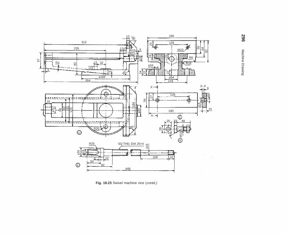
296M
achine Draw
ing
dharmd:\N
-Design\D
es18-2.pm5
Fig. 18.23 Swivel machine vice (contd.)
312
235
57
3
10 82
12
12 32
5
�184354
12
45°
16
1210 R10R12
5
�18
190
126
24
M10 50 6482
R6
R16�16
24 22 22
�54124
X–X6
�10
15
�14
126
190
54
27
X
X
�42
184
45°R20
25
�25 5882 92
120
1
525
28
10 48
6
M15R
4
�30 19
R25
650
92
12
SQ THD, DIA 25×4�16
108 22
448
80°
24 22 20

Assembly Drawings 297
dharmd:\N-Design\Des18-2.pm5
Fig. 18.23 Swivel machine vice
24 12
16
50
R10
R10
16
265888 26
190126
24 120 M10
62
R22
20
3 42
M12×35
2
152SQ THDDIA 25×4
21 42
22 60°
292
�5480° 18 14
2
25
12
1412
10 14
SP
3
2228
6�124
254
�202
R50
82 38 32
�32
�184
3
Part No. Name Matl Qty
123456
BodyMoving jawSwivel baseScrew rodJaw plateClamping bolt
111122
CSCSCIMS
HCSMS
Parts list
10
163
R3
50

298 Machine Drawing
dharmd:\N-Design\Des18-2.pm5
��������
Figure 18.23 represents the details of a swivel machine vice. Assemble the parts and draw,(i) sectional view from the front, (ii) view from above and (iii) sectional view from the left, withcutting plane passing through the axis of the clamping bolts.���� *���� +��
A jig is a work holding and tool guiding device which may be used for drilling, reaming, boringand similar operations in mass production.
Figure 18.24 shows the details of a drill jig used to produce six holes, spaced equally in acircular flange. The design allows for quick loading and unloading of work pieces. For unloading,the top nut 6 is loosened, the latch washer 8 swivelled out of zone and then the jig plate 3 is liftedto remove the work piece from its seating.
M20
54 �54
5×45
°
�502
25
�40�60 3 HOLES, M6 EQUI-SP
SLO
TT
ED
CH
EE
SE
HE
AD
SC
RE
WB
M6×
50
4
3035
84
98
M205
�216
5×45
°
�17
2516
M12�54
6 HOLES,
DIA 25
30°
60°
42
�160
3×45
°
5�60
�40
8
�110�156
3×45
°20
40
1
12
�178 42
R12
R33R32
R54
R15 M12
153×
45°�24
3
�16
36
�25
�18
25 7
CASE HARDENED9
Part No. Name Matl Qty
123456789
Base plateStemJig plateScrewStudNut M20Bush case hardenedLatch washerScrew
ClMSClMSMSMS
SteelMSMS
111311611
Parts list
3
2
Fig. 18.24 Drill jig
It may be noted that the jig plate is so designed, that the nut overall size is less than thesize of the central hole. This makes the loading and unloading easy, without totally removing the

Assembly Drawings 299
dharmd:\N-Design\Des18-2.pm5
nut from the stud 5. It may further be noted that the work piece is machined at the requiredsurface before loading in the jig. This is so, because, certain machined surfaces of the work piecemay be used for locating it in the jig.��������
Assemble the parts of the drill jig shown in Fig. 18.24 and draw, (i) sectional view from the frontand (ii) view from above.
���, -������� *���� +��
Figure 18.25 shows the details of an indexing drill jig used to drill six holes in the work piece (13).The jig consists of the bracket 1, on the top of which is fixed the jig plate 2. The plain drill
bush 6 and the slip bush 7 are located in the jig plate. The plain bush is fixed with interference fitin the plate, whereas the slip bush is provided with sliding fit in the plate and is removed tofacilitate loading of the job. The job is located in the jig by means of the locater 3 which is fastenedto the bracket 1 by means of the nut 11. Quick loading and unloading of the job is carried out bymeans of the quick acting knob 4. Two holes are drilled on the job through the bushes 6 and 7.The location of the remaining holes, which are at 90° intervals is obtained by the simple indexingmechanism provided by the ball catch assembly 5. The ball catch assembly consists of a M.S platewhich is fastened to the bracket by means of the socket headed screws 10. The required indexingis obtained by means of the spring 9, loaded ball 8, which is a part of the ball catch assembly.After the first operation, when the job is rotated in clockwise direction, the ball catch assemblyfacilitates location of the job at intervals of 90° rotation.��������
The details of an indexing drill jig are given in Fig. 18.25. Draw, (i) sectional view from the front,(ii) view from above and (iii) view from the right.
���� ���.��������� #�/��
The self-centring chuck is a work holding device mounted on the headstock spindle of a lathe. Itautomatically centres the workpiece by the three jaws, moving simultaneously to and from thecentre. Regular shaped objects such as rounds and hexagons are quickly held and centred in threejaw self-centring chucks.
Figure 18.26a shows the two views of a self-centring lathe chuck. The details of the assemblyare given in Fig. 18.26b. It consists of a face plate 1, and the scroll plate 3 is fitted into the circularrecess at the back of the face plate. Three pinions 4 are mounted in position in the face plate suchthat, their teeth engage with those on the back of the scroll plate. The back plate 2 is fastened tothe face plate by six screws 7. This assembly is fastened to the flange 5 by three socket headedscrews 8. The three jaws 6 are then engaged with the scroll plate. By rotating any one pinion bya chuck key (not shown), the three jaws move in the radial direction either to or from the centre.The threaded hole in the flange facilitates the mounting of the chuck in the threaded headstockspindle.��������
Figure 18.26b shows the details of a self-centring lathe chuck. Assemble the parts and draw to1 : 1 scale, the following:
(i) The view from the front, as seen from the side of the jaws, and(ii) The half sectional view from the right. Consider suitable local section for showing other
details.���� $�/� +�) #�/��
Four jaw chuck is a device used to hold jobs accurately on a lathe. Unlike three jaw self-centringchuck, it can hold both regular and irregular shapes of objects.

300M
achine Draw
ing
dharmd:\N
-Design\D
es18-2.pm5
Fig. 18.25 Indexing drill jig
13.5
30
96
1515
48
15 18 405
102 No’s M6
SOCKET HEADEDSCREW
18
�12
12
48 18
1818
18
�12 28 31
20
243 HOLES, M6
96
1
A
9
8
6
1.536 24 48
18
M12
�30
3
18
18
M12
15°
Tilt angle torelease knob
4
�20
5�10
18
�4.5
2.5
18
�4.5�10
7�32
13
4 HOLES, DIA 4.5
90°
�31
�58
X–X
5427
13.5X 13.5 2 HOLES,
DIA 4.5
�14
X
Detail at A
183 HOLES, DIA 17C-BORE
4812
18
2 HOLES,DIA 5
�10 �10
22.5 27
58
18
9
242
76
Part No. Name Matl Qty Part No. Name Matl Qty
1234567
BracketJig plateLocatorQuick acting knobBall catch assemblyDrill bushDrill slip bush
ClMSMSMSMS
HCSHCS
1111111
89
10111213
Ball 5SpringSocket head screwNut, M12Dowel pin, 5×35Workpiece
�
�
MSSteelMSMSMS
11512
Parts list
Ballcatch

Assembly Drawings 301
dharmd:\N-Design\Des18-2.pm5
8 5 7 2 1 3 6
4
Part No. Name Matl Qty
12345678
Face plateBack plateScroll platePinionFlangeJawSocket head screwSocket head screw
MSMS
MCSMCS
ClMCS
——
11131363
Parts list
Fig. 18.26a Self centring chuck
Fig. 18.26b Details of self centring chuck (contd.)
10
30 41821413
20
3 HOLES, M6DEEP 30
PCD 140
120° 10
3 HOLES, M6
PCD 503 HOLES,
DIA 10 PCD 140
120°
22
30
160
4124
6440 60 12
5
17
1254
58 TEETH12 PITCH
24
9°30
¢3
R5 R11 1
60
3.5 TURNS
SQ 4 SPIRAL
417
11°

302M
achine Draw
ing
dharmd:\N
-Design\D
es18-2.pm5
Fig. 18.26b Details of self centring chuck
20°�12
0
�40
�12
5�16
0
5 24
4
3H
OLE
S,D
IA10
PC
D14
0
3 HOLES, DIA 6
C’BORE DIA 10�22R30
X18
8�11
10
20Y �32
X2
Y
X–X
12
R9
R11
3H
OLE
S, DIA
6C
’BO
RE
DIA
10P
CD
50
Y–Y
46
4 4 R10
120°
8 8 8 8 88
R18
4
20
10
45°
56 R10
R70R45 R25
20
16
8
13
6
�30PCD 25
2212
5676
�10
19
�22 4
10
12 TEETH12 PITCH
256 M6
7
�10
70
35
M10
10
�16
8
3 HOLES, M6
EQUI-SP�140
5
�75
�50
.5
M50 20 �45
�12
0
6 R6
5020 3
�160
5
33
� 11� 11
11°

Assembly Drawings 303
dharmd:\N-Design\Des18-2.pm5
The isometric view of a four jaw chuck is shown in Fig. 18.27a. It consists of a cast ironbody 1, in which is located the screws 3 and the jaws 2 which engage with each other with squarethreads. The screws are held in position by the locators 4 which prevent their axial movement aswell. When the screws are operated by means of a chuck key (not shown), the jaws move towardsor away from the centre. Thus, the four jaws can be moved independently to grip the job firmly.The locators are fixed to the body by means of screws 5. The body of the chuck is fixed to the backplate by means of four M 18 bolts. The details of the chuck are illustrated in Fig. 18.27b.
3
2
4
1
Fig. 18.27a Four jaw chuck
��������
The details of a four aw chuck are shown in Fig. 18.27b. Assemble the parts and draw, (i) the viewfrom the front, as seen from the side of the jaws and (ii) the half sectional view from left.
Also consider suitable local section for showing other details.
�� '0�'�� 01* 23-��! �341�-15�
��� 5��� '��"�
A valve is used on a fluid line to check or control the fluid flow. It may be operated by the pressureof the fluid or by hand. A number of designs of valves are available; however the gate valvepermits the whole area of the passage for the flow of fluid, when fully opened. This minimizes anyenergy loss in the fluid flow.
Figure 18.28 shows the details of a gate valve. The wedge valve 4 in this design is guided bythe control screw 5. When fully opened, the wedge valve clears-off the passage in the valve body 1for the flow of fluid. The inside union 8 is slipped onto the stem from below. This is placed in theunion 2 and screwed. The wedge valve is threaded on the stem and the assembly is placed in thevalve body and screwed. The gland is placed from the top of the stem so that it enters the union.It is fixed in position by the union ring 3. Finally, the hand wheel 6 is placed on the square end ofthe screw and fixed in position by means of a nut (not shown). The gate valve may be fixed for anydirection of the fluid flow.

304M
achine Draw
ing
dharmd:\N
-Design\D
es18-2.pm5
Fig. 18.27b Details of four jaw chuck
20 20 8 HOLES, M6
�105 �200
4 HOLES, M18
66
6
�31
0
�28
5�55
�25
R13 10
1624
68
125
7530
9832 32
1010 62
DIA 24×3.5 SQ THD45°
8
24 2
108
4
6
9838 38
12
�20
DIA 24×3SQ THD
8 6 3
12
32 6
�25
11�12
�40
�55
2 HOLES, M6
CSK DIA 10
6
4
Sl. No. Name Matl Qty
12345
BodyJawsScrewLocatorMachine screws M6
ClCl
SteelSteel
—
14448
Parts list
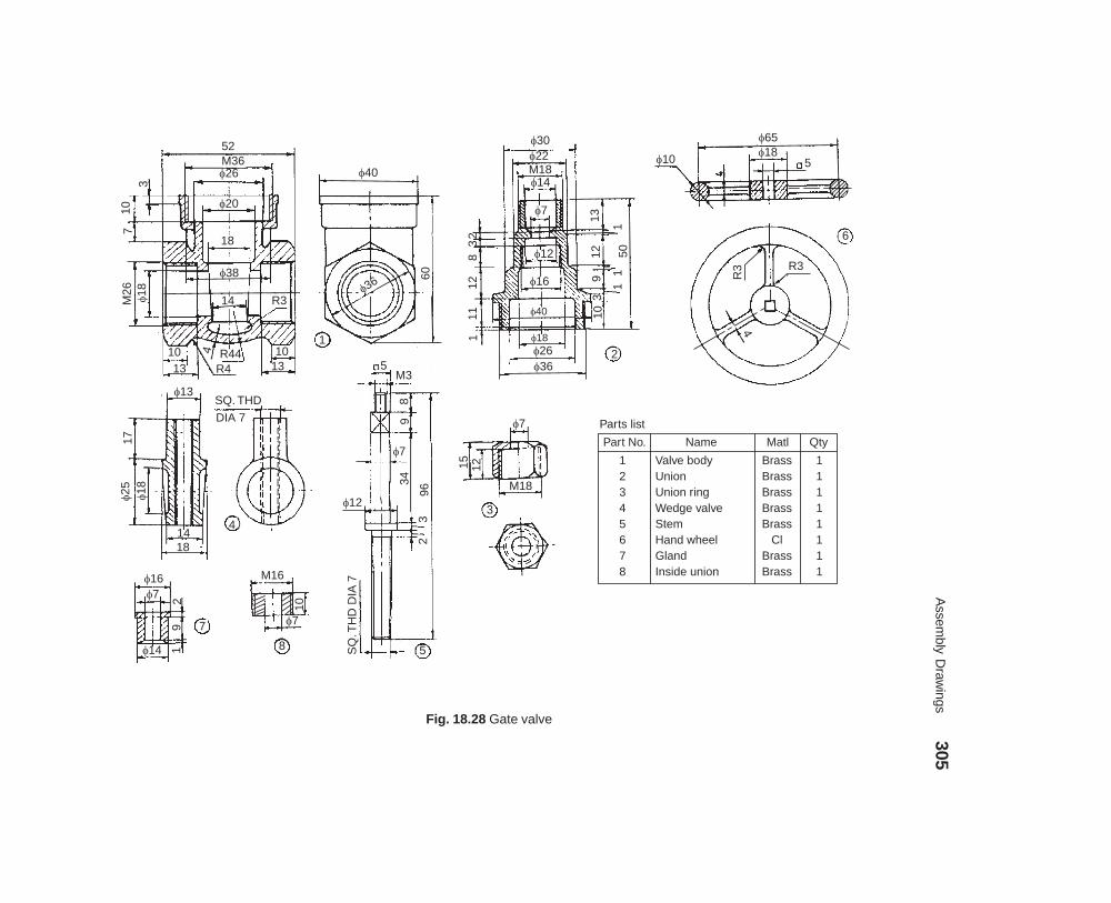
Assem
bly Draw
ings305
dharmd:\N
-Design\D
es18-2.pm5
Fig. 18.28 Gate valve
52M36
3
107
�26
�20
18
�38
M26
�18
14
1013
4 R44R4
1013
R3
1
�40
60
�36
�30�22
�14M18
�7
�12
�16
�40
�18�26�36
2
23
812
111
1312
93
10
50
�65�18
5�10
6
R3
R3
4
�13
17�25
�18
1418
4
SQ. THD
DIA 7
5M3
89
�7
34
�12
963
2
5SQ
.TH
DD
IA7�16
�7
29
1�14
M16
10
�7
8
�7
15 12M18
3
Part No. Name Matl Qty
12345678
Valve bodyUnionUnion ringWedge valveStemHand wheelGlandInside union
BrassBrassBrassBrassBrass
ClBrassBrass
11111111
Parts list
71
11
306 Machine Drawing
dharmd:\N-Design\Des18-3.pm5
��������
Figure 18.28 shows the details of a gate valve. Assemble the parts and draw to full scale, (i)sectional view from the front, (ii) the view from above and (iii) the view from the left.
��� ����� ���� ���� �����
Similar to any other valve, this valve is also used in a fluid line to control the fluid flow. In thefully open position, valve gets lifted by 5 mm from the seat to allow the fluid flow from left to right.
Figure 18.29 shows the details of the screw down stop valve. The sleeve 5 is mounted on thestem 8 by means of actuating screw 9. Valve seat 11 is attached to the collar 6 with the screw 12and then the collar 6 is screwed onto the sleeve 5, completing the valve assembly. Screwed sleeve10 is located in the bonnet 2 and this assembly is screwed onto the valve body 1 after slipping ontothe stem assembly. Gland 4 is located on the bonnet through the stem and packing 7 (not shownin figure) is used between the bonnet and gland, to stop any leakage of fluid. Gland is secured bythe cap nut 3. Hand wheel 13 is mounted on the stem, using the nut 14.
During operation of the hand wheel, the screw 9 either lifts the vlave, opening the fluidpassage or screws down the valve, closing the fluid passage. Hence, the name actuating screw.
��������
Figure 18.29 shows the details of a screw down stop valve. Assemble the parts and draw,(i) sectional view from the front and (ii) view from above.
��� ���������� ����� ������ ��!"
Valve is a device used for regulating the flow of fluid. In the non-return valve, the pressure of thefluid allows the flow in one direction only.
When the inlet pressure of the fluid is greater than the pressure at the top of the valve, itgets lifted and allows the fluid to flow past. However, as the fluid pressure builds-up more at thetop; the flow ceases and the fluid will not be permitted in the reverse direction, due to shutting ofthe valve automatically. It is used in boiler feed water system.
Figure 18.30 shows the details of a non-return valve. The fluid enters at the bottom of thevalve and leaves from the side. It consists of a body 1 with flanges at right angle, for the purposeof mounting the same. The valve seat 3 is introduced into the body from top and secured in placeby set-screw 6. The valve 4 is also introduced from top and located in the valve seat. The valveseat allows free sliding of the valve in it. The studs 5 are first screwed into the body and afterplacing the cover 2, it is tightened with nuts.
As water with pressure enters at the bottom of the valve, the valve gets lifted in the valveseat, allowing free flow of water through the exit. However, the amount of lift of the valve iscontrolled by the cover.
��������
The part drawings of a non-return valve are shown in Fig. 18.30. Assemble the parts and draw,(i) half sectional view from the front, (ii) view from the left and (iii) view from above.
��� ���������� �����
When a valve is operated by the pressure of a fluid, it is called a non-return valve, because, due tothe reduction in the pressure of the fluid, the valve automatically shuts-off, ensuring non-returnof the fluid. Figure 18.31a shows a brass/gun metal valve with a bevelled edge on the valve seat.The isometric view of the inverted valve shows the details of the webs. However, in the non-returnvalve, a separate valve seat is not provided.

Assem
bly Draw
ings307
dharmd:\N
-Design\D
es18-3.pm5
Fig. 18.29 Screw down stop valve
�39M32
R5
2M
20
213
5
10 R42�19R4
3 �12 R45
13
�551
R25
410
�35
40
1380
13
M4
14
�28M18�13
1 12
3
227
11
�71212
34
10
53
2M12�22M32�39
�20
M15
17
87 5
M4�12�30
6
�22�42
11 10
M12 �7
15
�10M4 92
112 7
2
1.5
�2�716
M12
�7
8
65
M4
79 1
6
�65�17�10
4
613
R3R3
4
15
�7 M18
10 103
5
�20
�7M155
3
�16�7
10 6
4
2 �13
M4
5 8
12
3
63
Sl. No. Name Matl. Qty.
1234567891011121314
Valve bodyBonnetGland tightening nutGlandSleeveCollerStuffing box packingStem with screwActuating screw endScrewed sleeveValve seatScrewHand wheelNut
CIBrassMS
BrassMSMS
AsbestosMSMS
BrassGMMSCIMS
11111111111111
Parts list

308 Machine Drawing
dharmd:\N-Design\Des18-3.pm5
Fig. 18.30 Non-return valve (Light duty)
Fig. 18.31a Valve and the seat
6 HOLES, M16 PCD150
�90
�120
2012
�126
20
12
50
�20
0
140
2012
40
12
140
�200
1
�90 12 M10
80
�25
3�100
�90
7
�190
�100
2038
�25
�20
�120
6 HOLES, DIA 18
PCD 150
�112
645 �90
�100
3
22
45°3
TO SUITDIA 10
SET SCREWEND
�25
45° 25
75
48
R100
�90
3 WINGS,THICK 8
4
M10 M1628 20
60
6 5
No. Name Matl Qty123456
BodyCoverValve seatValveStud with nutSet screw
BrassBrass
BronzeBrassMSMS
111161
Parts list
6
2
R100

Assem
bly Draw
ings309
dharmd:\N
-Design\D
es18-3.pm5
R18
64
�62Y–Y
M42
DX
100
64
�50
4 HOLES,
DIA 14
166
�32�25
X
2832
443
322
44
M42M24
5×45
°
�38
25 23
5221 19 13
3
19
�19M30
60 A/C
�58
44 A/C
1650
286
�13
M42
R6
6
3
60° M30
3
3219
�1944A/C4
�35
�25
5
�13SLOT 3
R6
5
3
4428
3
A
M33�50
58X–X
�25
1B
�44
1325
70
3×45°
44
4219 C
M42�64
�50
6�32
�25Y
6 �32
3×45
°3
32 M24
�19
130
2
20 2×45
°
13
Part No. Name Matl Qty1
2
3
4
5
6
Valve body
Spindle
Gland bush
Gland
Valve
Valve stop
Cl
Brass
Brass
Brass
Brass
Brass
1
1
1
1
1
1
Parts list3
3
6
Fig. 18.31b Non-return valve

310 Machine Drawing
dharmd:\N-Design\Des18-3.pm5
Figure 18.31b shows the details of a non-return valve. Fluid flow enters the valve at A(inlet) and leaves the valve at B (outlet). The gland bush 3 and the gland 4 are first assembled andscrewed onto the spindle 2 and assembled into the valve body 1 at C. By operating the spindle, thefluid outlet B is either closed or kept open. The valve 5 is positioned in the body through thepassage D and it is kept floating. The valve stop 6 is screwed into the body at D and is used tocontrol the amount of lift of the valve. The fluid inlet connection to the valve is made at A.
When the spindle is operated and the outlet is open; due to the pressure of the inlet fluid,valve is lifted and passage is established from A through B. When the pressure of the incomingfluid is reduced, the valve automatically shuts-off the inlet passage, ensuring non-return of thefluid in the opposite direction.
��������
The details of a non-return valve are shown in Fig. 18.31b. Assemble the parts and draw thefollowing veiws to a suitable scale:
(i) Sectional view from the front, taking the section through Y-Y, and,(ii) Sectional view from above, considering section through X-X.
������������
This valve is used to control air or gas supply. The details of an air cock are shown in Fig. 18.32.It consists of a plug 2 which is inserted into the body 1, from the bottom. The rectangular sectionedspring 4 is placed in position at the bottom of the plug and seated over the screw cap 3. The screwcap is operated to adjust the spring tension. Lever 5 with square hole is used to operate the cock.By a mere 90° turn, the cock is either opened or closed fully.
�������
The details of an air cock are shown in Fig. 18.32. Assemble the parts and draw, (i) half sectionalview from the front, (ii) view from the right and (iii) the view from above.
������������������
The blow-off cock is fitted at the lowest part of the boiler, to remove the sediments collected. Whenoperated, water and sediments rush through the side flange of the cock (due to pressure in theboiler) and escape through the bottom flange. Figure 18.33 shows the parts of a blow-off cock. Itconsists of a hollow conical body 1 into which the cock 2 is located. Both the cock and body havevertical slots and when they are aligned, water gushes through the cock. Gland 3 is fastened tothe body by means of studs 4. To prevent leakage, packing material is placed between the cockand gland. Figure 19.17 shows the assembly drawing of the blow-off cock.
�������
The part drawings of a blow-off cock are shown in Fig. 18.33. Asemble the parts and draw,(i) sectional view from the front and (ii) view from above.
��������������� ������
It is used in boilers to regulate the supply of feed water and to maintain the water level. It is fittedclose to the boiler shell and in the feed pipe line. Figure 18.34 shows the details of a feed checkvalve. The valve prevents water from being returned to the supply line, due to steam pressure inthe boiler. Hence, it functions like a non-return valve.
It consists of a body with two flanges at right angle and feed water enters at the bottom andenters the boiler through the side opening. The valve seat 5 is introduced into the body of the valvefrom the top opening. The valve 4 is located in the valve seat, which guides the movement of the

Assembly Drawings 311
dharmd:\N-Design\Des18-3.pm5
Fig. 18.32 Air cock
190
�56
40 12R12
3215
10×
4 56
4�26
�70
�48
12
22
�106
�4232
21
�4820
48
50
123
30
�26
�72
24 2
3
�70
50
10 22
76
M82�48
10
M52
�74
5
1
�80
2683 86
10 28
M82�60�46 3
16 2210
20
74�106
5
Part No. Name Matl Qty
1
2
3
4
5
Body
Plug
Screw cap
Spring
Lever
Cl
Cl
MS
Spring S
FS
1
1
1
1
1
Parts list
5
3

312M
achine Draw
ing
dharmd:\N
-Design\D
es18-3.pm5
Fig. 18.33 Blow-off cock
40 1152
�82
24
�94
14°
�40
4 HOLES,
DIA 12, PCD 100
�54�64
�44
�132 1
1093 1122
�60
8010
�11
2
�72
4 HOLES,DIA 12, PCD 92
11480
R17
4 HOLES,
M12
1088 42
36
8
6
�48�80
32
8
8
2230
60 100
66
22
�542
3040
40
M12
7015 5 4
�24
�78�68�56
570
9 4
22
�64
9 64 39
4 HOLES,DIA 12
R1780114
3
Sl. No. Name Matl. Qty.
1234
BodyCockGlandStud
CSGMCSMS
1114
Parts list

Assem
bly Draw
ings313
dharmd:\N
-Design\D
es18-3.pm5
Fig. 18.34 Feed check valve
�206
�108R30
12
RIB, THICK12
12R10
20
12
140
4035
16
Rib
12
11
R912
�88
�80
�206130
12
140
12R
12
Rib
�75
�96
�20
6
R12
16 15
6 HOLES,DIA 6
PCD 1526 HOLES, M6DEEP 17 PCD 152
R10
�206
�83
�32
45°
643
3 4
6
744 8
103
M16M16
52
2215
2 HOLES, M16
DEEP 15
�206
76
�102
45°
640
3
�75�88
5
�32
1344
30°
�44 6
�10
R25
R13
76
�102�44
10
�108
�32
M25
�88�22
2038
120
165
2�44
4 ARMS12
�24
26 �26�140
12
8
�32
10 50 178
M25
�22 12
24 14
M10
11
9
32
76
18
M10
M10
No. Name Matl. Qty
123456789
1011
BodyCoverSpindleValveValve seatGlandHand wheelStudStudNutNut
11111116263
ClCl
MSGMGMGMCl
MSMSMSMS
Parts list
�128
3
3
33°
44
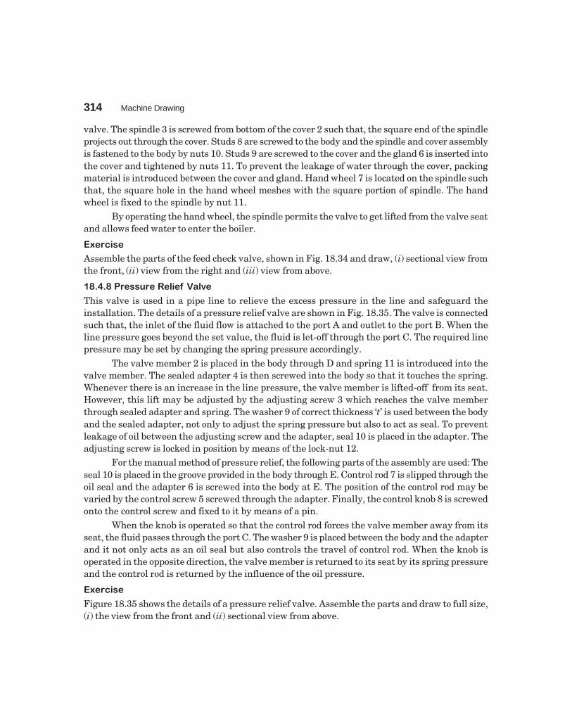
314 Machine Drawing
dharmd:\N-Design\Des18-3.pm5
valve. The spindle 3 is screwed from bottom of the cover 2 such that, the square end of the spindleprojects out through the cover. Studs 8 are screwed to the body and the spindle and cover assemblyis fastened to the body by nuts 10. Studs 9 are screwed to the cover and the gland 6 is inserted intothe cover and tightened by nuts 11. To prevent the leakage of water through the cover, packingmaterial is introduced between the cover and gland. Hand wheel 7 is located on the spindle suchthat, the square hole in the hand wheel meshes with the square portion of spindle. The handwheel is fixed to the spindle by nut 11.
By operating the hand wheel, the spindle permits the valve to get lifted from the valve seatand allows feed water to enter the boiler.
��������
Assemble the parts of the feed check valve, shown in Fig. 18.34 and draw, (i) sectional view fromthe front, (ii) view from the right and (iii) view from above.
�� #������� $����% �����
This valve is used in a pipe line to relieve the excess pressure in the line and safeguard theinstallation. The details of a pressure relief valve are shown in Fig. 18.35. The valve is connectedsuch that, the inlet of the fluid flow is attached to the port A and outlet to the port B. When theline pressure goes beyond the set value, the fluid is let-off through the port C. The required linepressure may be set by changing the spring pressure accordingly.
The valve member 2 is placed in the body through D and spring 11 is introduced into thevalve member. The sealed adapter 4 is then screwed into the body so that it touches the spring.Whenever there is an increase in the line pressure, the valve member is lifted-off from its seat.However, this lift may be adjusted by the adjusting screw 3 which reaches the valve memberthrough sealed adapter and spring. The washer 9 of correct thickness ‘t’ is used between the bodyand the sealed adapter, not only to adjust the spring pressure but also to act as seal. To preventleakage of oil between the adjusting screw and the adapter, seal 10 is placed in the adapter. Theadjusting screw is locked in position by means of the lock-nut 12.
For the manual method of pressure relief, the following parts of the assembly are used: Theseal 10 is placed in the groove provided in the body through E. Control rod 7 is slipped through theoil seal and the adapter 6 is screwed into the body at E. The position of the control rod may bevaried by the control screw 5 screwed through the adapter. Finally, the control knob 8 is screwedonto the control screw and fixed to it by means of a pin.
When the knob is operated so that the control rod forces the valve member away from itsseat, the fluid passes through the port C. The washer 9 is placed between the body and the adapterand it not only acts as an oil seal but also controls the travel of control rod. When the knob isoperated in the opposite direction, the valve member is returned to its seat by its spring pressureand the control rod is returned by the influence of the oil pressure.
��������
Figure 18.35 shows the details of a pressure relief valve. Assemble the parts and draw to full size,(i) the view from the front and (ii) sectional view from above.

Assembly Drawings 315
dharmd:\N-Design\Des18-3.pm5
Fig. 18.35 Pressure relief valve
��& '���� ��%��! �����
Safety valves are used to release some of the steam from the boiler when the pressure rises higherthan the safe limit.
In a lever safety valve, a load is applied through a lever, by placing a suitable weight atsome distance from the centre line of the valve to counter-balance the steam pressure in theboiler. The distance can be adjusted by moving the weight along the lever for adjusting theblowing-off pressure. The lever safety valves are suitable for stationery boilers.
12
�3 30
°
1×45° 8 1426
�9
�14
1.5 1016
M20
�11 �6
M8
30A
/F
3 3
184
2
30 221×45°
�5 M
8 4
1.5
3
7
�20
�30
9
M8
�3
5
640
�5
1×45°3
30A
/F10 12
2
M8
M20
6
30
�10
30° 1×45°
17 �3
�6
�5
�11
10
9224 3 40
3
Port B 30°
16
D
�6
�8
�14
M20
14
48 �11 E
16 3
3
�5�8
8
Port C
48Port A1
Port C
�30
E 12
R8
R8
PORT BM12 DEEP 9
30
�5
3528
R8
30
D
�64
2210
5 R5 15°
6 15 18
�3M8�208
3
No. Name Matl. Qty
123456789
1011
12
BodyValve memberAdjusting screwSealed adapterControl screwAdapterControl rodControl knobWasherSealSpring : wire dia
1mm : OD = 8Locknut M8
f
11111111221
1
CIMSMSMSMSMSMS
EboniteRubberRubber
Spring S
MS
Parts list

316M
achine Draw
ing
dharmd:\N
-Design\D
es18-3.pm5
Fig. 18.36 Lever safety valve (contd.)
�260�140
�134 10
25
R9218
M11432
�10
0
�23
0
1818
�124
�100
�230
18
15
�50
2866
168
292
25
6 HOLES, DIA 20
EQUI-SP PCD 180 1
188
�12
8
6 HOLES, M20
EQUI-SP
�210
60°
60°
�22 R30
94
44
10042
�64
�40
M20
30
�36
�76�140�260
825
12
24
28 42
124
1225
M20
9
�36
�28
24
�38 6
5
4
�21
0
6822
22
128
60°
60°
6 HOLES, DIA 20EQUI-SP�128
�10426
28
�100
M114
2 2N
OT
CH
ES
6×
12 5020
�104
85
50
8
�1003
1832
M20
28
18

Assem
bly Draw
ings317
dharmd:\N
-Design\D
es18-3.pm5
2 HOLES, DIA 22
100R32
10270
22
64 �15
1260 16
�22 R20 12 1224
32 36 50
5 �28
R67
6
44
�12
6
�28
200
4482
222
66
�10
2�15
20
40
S35
6�
12 144
�6 �12
�16
676 3 13
�68
�22 �26
80 611
60 5
�26
8�6 �
22 8
Part No. Name Matl Qty
1234567
BodyValve seatValveCoverCover bushSpindleToggle
1111111
ClGMGMCl
BrassMSMS
Part No. Name Matl Qty
89
1011121314
Toggle-pinLever guideLeverFulcrum pinWeightLever pinStud with nut M20
1111116
MSMSFSMSCl
MS—
Parts list
�76
Fig. 18.36 Lever safety valve

318 Machine Drawing
dharmd:\N-Design\Des18-3.pm5
The details of a simple lever safety valve are shown in Fig. 18.36. In this, valve seat 2 isscrewed in the valve body 1. The spindle 6 and toggle 7 together keeps the valve 3 pressed againstthe seat. The top of the valve body is closed with a cover 4 with the help of six studs 14. A coverbush 5 is used to prevent the leakage through the central hole of the cover. A lever guide 9 isscrewed to the cover in order to restrict the lever movement. The weight 12 is attached to thelever 10 by means of lever pin 13. The toggle is held in position by means of toggle pin 8. Fulcrumpin 11 is used to connect the lever and the cover, to act as the fulcrum.
��������
The details of a lever safety valve are shown in Fig. 18.36. Assemble the details and draw,(i) The sectional view from the front, and
(ii) The view from above.
���( ������ '�� � $����% �����
Safety or relief valves are used as boiler mountings and they let off steam from inside the boilerwhenever the pressure exceeds the set value. Thus, these valves safe guard the boilers. Thepressure may be set by using a dead weight or a tension spring with tension adjustmentarrangement.
Figure 18.37 shows the details of a spring loaded relief valve in which a tension spring isused to set a pre-determined value for the steam pressure in the boiler. Valve 3 is placed verticallyinside the valve body 1 and the valve seat is an integral part of the valve body, in the designconsidered. Stem 6 is located in the valve, with pointed end entering into the valve. Flange 7 isnow placed over this assembly and fastened to the valve body by fulcrum bolt 4. Lever 2 isattached to the fulcrum bolt by using the fulcrum pin 5 such that, the lever rests on the stem 6.One end of the tension spring 8 is attached to the lever and the other end to the tension adjustingbolt 9. The tension adjusting bolt is attached to a base and the spring tension can thus be adjustedto any required value.
��������
Assemble the parts of a spring loaded relief valve, shown in Fig. 18.37 and draw the followingviews:
(i) Sectional view from the front, and(ii) View from the right.
���� $�)�*����) ��%��! �����
It is a boiler mounting and a safety device which protects the boiler against building-up of excesspressure. The spring used in the safety valve is set to act when the steam pressure exceeds the setvalue and allows the steam to escape. Thus, only the permissible value of steam pressure isallowed inside the boiler.
Figure 18.38 shows the details of Ramsbottom safety valve. It consists of housing 1 withtwo valve chests. The valve seats 3 are screwed into the housing and valves 2 are located in thevalve seats. The eye bolt 8 is fastened to the bridge of the housing, by means of washer 9 and boththe nuts 10 and 11. Pivot 4 is pinned to the lever 5 and it is placed over the valves and held inposition by safety links 7 and spring 6. The safety links 7 are fixed at one end to the lever andthe other end to the eye bolt 8 by pins 12 and split pins 13. The required rigidity is provided to this
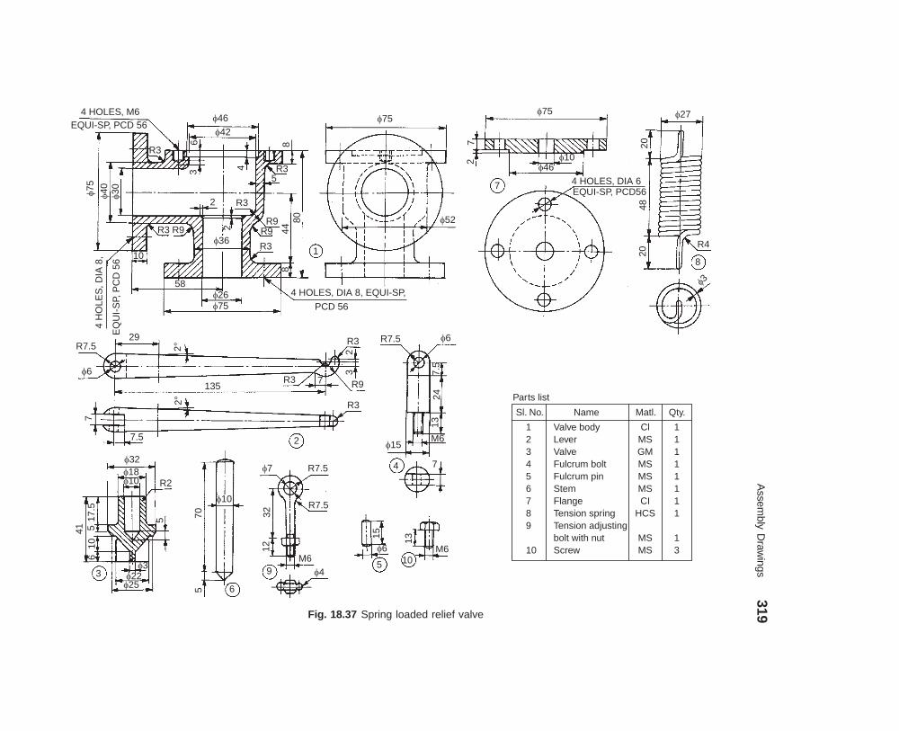
Assem
bly Draw
ings319
dharmd:\N
-Design\D
es18-3.pm5
Fig. 18.37 Spring loaded relief valve
4 HOLES, M6EQUI-SP, PCD 56
R3
6
�46
�42
3 4
8
R35
�75
�40
�30
R3 R9
10
4H
OLE
S,D
IA8,
EQ
UI-
SP,
PC
D56
58�26�75
�36R3
R9R9
4480
�75
�52
1
4 HOLES, DIA 8, EQUI-SP,
PCD 56
�75
72 �10
�46
7 4 HOLES, DIA 6EQUI-SP, PCD56
�27
2048
20
R4
8
�3
R7.5
�6
29
2°
135R3
R32
3
R97
R32°
7
7.5
�32�18�10 R2
517.5
510
41
�3�22
�25
�10
70
65
9
�7 R7.5
R7.5
3212
M6�4
R7.5 �6
7.5
2413
M6�15
4 7
15
�6
5 10
13
M6
R32
2
3
6
8
Sl. No. Name Matl. Qty.
123456789
10
Valve bodyLeverValveFulcrum boltFulcrum pinStemFlangeTension springTension adjustingbolt with nutScrew
ClMSGMMSMSMSCI
HCS
MSMS
11111111
13
Parts list
2

320M
achine Draw
ing
dharmd:\N
-Design\D
es18-3.pm5
Fig. 18.38 Ramsbottom safety valve (contd.)
96 96M80 �105
52 �60 48
R12
18
12 �72
R96
R12R60R18
�96
6 HOLES, DIA 20 PCD 192
1
192
408
R12 96 96 24
4632
1512
�12 12
�12 R12 R12
R18 60 R660°
46
9
6492
18
24
60
R36
24 R12
24
�192�240
90°
�124�112
14 348 5680
�54M80
4
�54
15
�90
4×45
°
60
5
36
4
3
�64
90°90°
Part No. Name Matl Qty
123456789
10111213
HousingEye boltLinkValve seatValvePivotPinSplit pinLeverSpringWasherLock-nut, M20, 12 ThickNut, M20, 20 Thick
ClMSMS
GunmetalGunmetal
MSMSMSMS
Spring steelMSMSMS
1122213311111
Parts list
R24
4
4

Assembly Drawings 321
dharmd:\N-Design\Des18-3.pm5
R12
2HO
LES
,DIA
12
15
SQ20
M20
3245
1012
0
f12
24R12 6
24
15
46
f10
60°
1410
26 324
f20
f12
f3
2
f40 12
124
24
R12 2 HOLES,
DIA 12
3
TH
ICK
6
6
7
2011
�60
20�3
810
6
��0
R25
R12
15
175
6
Fig. 18.38 Ramsbottom safety valve
assembly by fixing the spring 6 between the eye bolt and the lever (holes are provided in the leverand eye bolt for this purpose). When the set value of the pressure exceeds in the boiler, the levermoves and allows the valves to get lifted from the seats concerned. The movement of the lever ispermitted due to the slot provided centrally in it and returns to the original position due to springaction. Figure 19.19 shows the assembled views of the Ramsbottom safety valve.
��������
Assemble the parts of the Ramsbottom safety valve, shown in Fig. 18.38 and draw, (i) sectionalview from the front and (ii) sectional left side view.
�+ ,-�.�''/��01� #/$2�
�+� ���3�� �� ������ 4����
This joint is used to connect two circular rods and subjected to axial loads. For this purpose, theends of the rods are shaped suitably to form a socket at one end while the other rod end as a spigotand slots are made.
Figure 18.39 shows the details of a socket and spigot joint. The spigot end of the rod 2 isinserted into the socket end of the rod 1. After aligning the socket and spigot ends, the cotter 3 isdriven-in, forming the joint. Figure 6.13 shows the assembly drawing of the socket and spigotjoint.

322 Machine Drawing
dharmd:\N-Design\Des18-3.pm5
105
28 SLOT,32×8
28
�46
�25
�35 �64
SLOPE,
1:30 30
THICK, 8 3
30
SLO
PE
,1:3
0
100
�32
1
8
94
SLOT,32×8
24 12
�25
�46
SLOPE,
1:30 2
8
Sl. No. Name Matl. Qty.
123
Socket endSpigot endCotter
MSMS
HCS
111
Parts list
Fig. 18.39 Socket and spigot joint
��������
Assemble the parts of a socket and spigot joint, shown in Fig. 18.39 and draw the following views:
(i) Half sectional view from the front, with top half in section, and
(ii) View from the right.
�+� 5���3�� 4����
This is a pin joint and is used to connect two circular rods subjected to axial loads. Compared to asocket and spigot joint, wherein the axes of both the rods should be in the same plane; in theknuckle joint, one of the rods can be swiveled through some angle about the connecting pin, i.e.,the axes of the two rods could be inclined to each other.
Figure 18.40 shows the details of a knuckle joint. The eye end of the rod 2 is inserted intothe fork end 1 of the other rod. Then, pin 3 is inserted through the holes in the ends of the rodsand held in position by the collar 4 and taper pin 5. Figure 6.15 shows the assembly drawing.
��������
Assemble the parts of a knuckle joint, shown in Fig. 18.40 and draw, (i) sectional view form thefront and (ii) view from above.

Assembly Drawings 323
dharmd:\N-Design\Des18-3.pm5
10430
�25
R32 �24
1828
18
8012
�38
�243
10
4 12
�38 �24�5 5
44
86
�24
�25
R24
28
2
1
28
R24
Sl. No. Name Matl. Qty.
12345
Fork endEye endPinCollarTaper pin
Forged steelForged steel
Mild steelMild steelMild steel
11111
Parts list
Fig. 18.40 Knuckle joint
�+� #������� 6����� .�������
Couplings are used to join two shafts so that they act as a single unit during rotation and powercan be transmitted from one shaft to the other. The protected flanged coupling is a rigid shaftcoupling, the axes of the shafts being collinear. Figure 18.41 shows the various parts of a protectedflanged coupling. The flanges 2 and 3 are mounted at the ends of two shafts 1 by means of keys 5.Later, the two flanges are connected to each other by means of bolts with nuts 4. In this rigidcoupling, the bolt heads and nuts are located in the annular recesses provided on the flanges andso are not exposed. Hence, the name protected flanged coupling. Figure 7.5 shows the assemblydrawing.
��������
Assemble the parts of a protected flanged coupling shown in Fig. 18.41 and draw the followingviews:
(i) Half sectional view from the front, with top half in section, and(ii) View from the right.
�+� 7���� ���� 2!�� 6����� .�������
This coupling is also used to join two circular shafts. However, this is not a rigid coupling, but aflexible one. Flexible couplings are preferred to rigid ones, as perfect alignment of two shafts isdifficult to achieve; which is the requisite condition for rigid couplings.

324 Machine Drawing
dharmd:\N-Design\Des18-3.pm5
20
�96
5�96
�19
2
230 44
4 HOLES, DIA 16
EQUI-SP
KEY WAY,
14×5
�50
�196
�208
20
�96
3
3
44 30
�16
4
KEY WAY,
14×5
�50
1SLOPE,
1:100 10
1476
5
Sl. No. Name Matl. Qty.
12345
ShaftFlangeFlangeBolt with nutKey
MSCICIMSMS
21142
Parts list
Fig. 18.41 Protected flanged coupling
Figure 18.42 shows various components of a bushed-pin type flanged coupling. Flanges 1and 2 are mounted on the ends of shafts 3 by using sunk keys 5. The smaller ends of pins 4 arerigidly fixed to the flange 2 by means of nuts, whereas the enlarged ends, covered with flexiblebushes 6, are positioned in the flange 1. The flexible medium takes care of mis-alignment if any,and also acts as a shock absorber. These couplings are used to connect prime mover or an electricmotor and a centrifugal pump, electric motor and a reduction gear, etc. Figure 7.7 shows theassembly drawing.
��������
Assemble the parts of the bushed pin type flanged coupling shown in Fig. 18.42 and draw, (i) halfsectional view from the front, with top half in section and (ii) view from the right.
�++ 0� ��) .�������
This coupling is known as a non-aligned coupling and is used to connect two parallel shafts,whose axes are at a small distance apart. Figure 18.43 shows various parts of a Oldham coupling.

Assembly Drawings 325
dharmd:\N-Design\Des18-3.pm5
KEY WAY,
8 × 4
�25
SLOPE,1:100
3
45 8
5
8
25
�42
�88
18 20 1 4 HOLES,
DIA 15
KEY WAY,
8 × 4 �112
�25
KEY WAY,
8 × 4
4 HOLES,DIA 8
5
�25
�102
2
�88
20 18
12�42
�11
2
�12
5
�10
23 12 8
6
�15
M8
4
Sl. No. Name Matl. Qty.
123456
FlangeFlangeShaftPin with nutFeather keyBush
CICIMSMSMS
Nylon
1124216
Parts list
Fig. 18.42 Bushed-pin type flanged coupling

326 Machine Drawing
dharmd:\N-Design\Des18-3.pm5
KEY WAY,
10×4
12
�30
�60
130 20
10
�10
0
�100
12 2
12
10KEY WAY,
10 × 4
3 �30
50
10
10
4
Sl. No. Name Matl. Qty.
1234
FlangeDiscShaftKey
MSMSMSMS
2122
Parts list
Fig. 18.43 Oldham coupling
The two flanges 1 are mounted on the ends of shafts 3 by means of sunk keys 4. The flangesare having rectangular slots in them. These flanges are set such that, the slots in them are atright angle to each other. The circular disc 2 is now positioned in-between them so that theprojections in the circular disc, enter into the corresponding slots of the flanges. During rotationof the shafts, the central disc slides in the slots of the flanges. Figure 7.12b shows the assemblydrawing.
��������
Assemble the parts of the Oldham coupling shown in Fig. 18.43 and draw, (i) sectional view fromthe front and (ii) view from the left.
�+8 1�������� .�������
This is a rigid coupling and is used to connect two shafts, whose axes intersect if extended.

Assembly Drawings 327
dharmd:\N-Design\Des18-3.pm5
KEY WAY,
8 × 4
�30
1656
16
10 1848
2
�16
R15
57 �55
�16
56
�16
18
�303
�30
56
4
KEY WAY,
8 × 4
�30
SLOPE,
1:100
40
1
6
8
8
�25
10
�16
6
100
�25
�1612
6
5
HOLE FOR DIA 3
TAPER PIN
Sl. No. Name Matl. Qty.
123456
ShaftForkCentral blockPinCollarKey
MSFSFSMSMSMS
221222
Parts list
Fig. 18.44 Universal coupling
Figure 18.44 shows the details of universal coupling. The forks 2 are mounted at the endsof two shafts 1, making use of sunk keys 6. The central block 3, having two arms at right angleto each other, is placed between the forks and connected to both of them by using pins 4 andcollars 5. A taper pin (not shown) is used to keep the pins 4 in position. During rotation of shafts,the angle between them can be varied. Figure 7.11b shows the assembly drawing.
��������
Assemble the parts of universal coupling and, shown in Fig. 18.44 and draw, (i) sectional viewfrom the front and (ii) view from the right.
�+9 #��))�� 7���3
This bearing is used for long shafts, requiring intermediate support, especially when the shaftcannot be introduced into the bearing, end-wise.
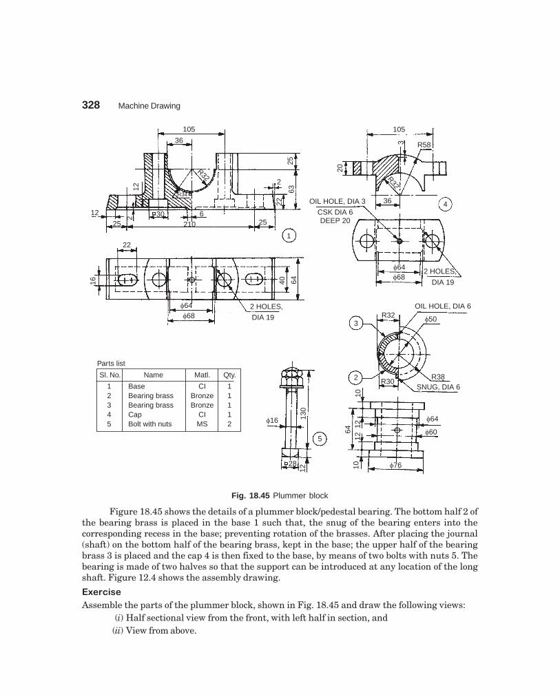
328 Machine Drawing
dharmd:\N-Design\Des18-4.pm5
105
36
R32
R34
12
12
25
2 30 6210
2563
2
22
25
122
16
�64�68
2 HOLES,
DIA 19
40 64
105
R583
20
R32
436OIL HOLE, DIA 3
CSK DIA 6DEEP 20
�64�68
2 HOLES,
DIA 19
OIL HOLE, DIA 6
�50R323
2 R30R38
SNUG, DIA 6
1064
1212
�64
�60
�7610
5
28
12
�16 130
Sl. No. Name Matl. Qty.
12345
BaseBearing brassBearing brassCapBolt with nuts
CIBronzeBronze
CIMS
11112
Parts list
Fig. 18.45 Plummer block
Figure 18.45 shows the details of a plummer block/pedestal bearing. The bottom half 2 ofthe bearing brass is placed in the base 1 such that, the snug of the bearing enters into thecorresponding recess in the base; preventing rotation of the brasses. After placing the journal(shaft) on the bottom half of the bearing brass, kept in the base; the upper half of the bearingbrass 3 is placed and the cap 4 is then fixed to the base, by means of two bolts with nuts 5. Thebearing is made of two halves so that the support can be introduced at any location of the longshaft. Figure 12.4 shows the assembly drawing.
��������
Assemble the parts of the plummer block, shown in Fig. 18.45 and draw the following views:(i) Half sectional view from the front, with left half in section, and
(ii) View from above.

Assembly Drawings 329
dharmd:\N-Design\Des18-4.pm5
������������� ����
It is used to support shafts where there are possibilities of misalignment. These, like plummerblocks, may be placed at any desired location.
Figure 18.46 shows the details of a swivelling or self-aligning bearing. If consists of thefork 3 which is fitted into the body 1 by means of the spindle 4, and by adjusting the spindleposition, the fork may be elevated to any required height. It is then free to swivel in a horizontalplane. The bearing is then supported in the fork by means of two set screws 8. The connectionbetween the fork and the screws is such that, the bearing is free to swivel in a vertical plane. Theflexibility in both the planes is thus made available.
Accurate alignment may be obtained by screw height and slide adjustments. After therequired adjustments are made to suit the shaft position, these are then locked. The lock-nut 5with the set screw 7 passing through it, and another set screw 6 passing through the body areused to lock the height adjustment. The tips of these set screws tighten upon the brass disks 9and 10, thus preventing damage to the threads on the spindle. Hexagonal nuts 11 are used withthe side adjustment set screws to lock them in position. The gun metal bush 12 is used inside thebearing.
������
Assemble the parts of the swivel bearing shown in Fig. 18.46 and draw, (i) half sectional viewfrom the front, with left half in section, (ii) view from the left and (iii) view from above.
������������������ ����
This consists of two bearings, one in the form of a disc and the other in the form of a bush. It isintended to support a vertical shaft under axial load. The axial load is resisted by the disc shapedbearing provided at the bottom of the shaft, whereas the bush bearing resists radial load on theshaft.
The details of a foot-step bearing are shown in Fig. 18.47. The disc 3 is located in the body1 after placing the pin 5 in the corresponding hole in the body. This prevents the rotation of thedisc, due to rotation of the vartical shaft. Bush 2 is now placed in the body such that, the snug onthe bush rests in the recess provided in the body. This assembly is now ready to support thevertical shaft 4. Figure 12.9 shows the assembly drawing.
������
Assemble the parts of a foot-step bearing, shown in Fig. 18.47 and draw, (i) sectional view fromthe front and (ii) view from above.

330M
achine Draw
ing
dharmd:\N
-Design\D
es18-4.pm5
Fig. 18.46 Swivel bearing
�45M21×2.5
18
6�42
�66
47
709
�60�96
1
72
18 9
R36
M8
126�39M21
16
8
5M6
�6
29
�5
2
10
14 1460
M9
9
�33�26
5
546
18�2117
�60 3
8
21 30
M21
�26
9
80
96
4
OIL HOLE, DIA 3CSK AT 90°
�15
12D
IA2,
CS
K
DIA
82�39
642
6
�1857
�24�48
M8
6
15
2460°
M9 30
8
M6
15
7
2
12
8
11
4
5
7 10
1
6 9
Part No. Name Matl Qty
123456789
101112
BodyBearingForkSpindleLock nutSet screwSet screwSet screwDiscDiscNut, M9Bush
ClCl
MSMSMSMSMSMS
BrassBrassMSGM
111111121121
Parts list
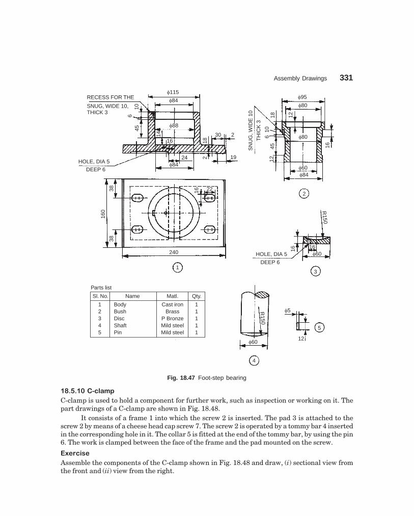
Assembly Drawings 331
dharmd:\N-Design\Des18-4.pm5
RECESS FOR THE
SNUG, WIDE 10,THICK 3
�115
�84
106
45
�88
14
16 18
30 2
19224�84HOLE, DIA 5
DEEP 6
�95
�80
18 12
�80
16
106
SN
UG
,WID
E10
TH
ICK
3
4512
�60�84
2
38
160
38
16 22
240
1
R150
16�60HOLE, DIA 5
DEEP 6
3
R150
�60
�5
12
5
4
16Sl. No. Name Matl. Qty.
12345
BodyBushDiscShaftPin
Cast ironBrass
P BronzeMild steelMild steel
11111
Parts list
Fig. 18.47 Foot-step bearing
������������ ��
C-clamp is used to hold a component for further work, such as inspection or working on it. Thepart drawings of a C-clamp are shown in Fig. 18.48.
It consists of a frame 1 into which the screw 2 is inserted. The pad 3 is attached to thescrew 2 by means of a cheese head cap screw 7. The screw 2 is operated by a tommy bar 4 insertedin the corresponding hole in it. The collar 5 is fitted at the end of the tommy bar, by using the pin6. The work is clamped between the face of the frame and the pad mounted on the screw.
������
Assemble the components of the C-clamp shown in Fig. 18.48 and draw, (i) sectional view fromthe front and (ii) view from the right.

332 Machine Drawing
dharmd:\N-Design\Des18-4.pm5
SQ. THREAD, DIA 24
545
8468 75
8
245
45
X
R25
R25R12
�4535
20
1X
�32
�12
32
SQ. THD DIA 24
2
190
2810
X–X
50
�20
45M6, DEEP 5
210
10
�12
HOLE, DIA 3 REAM
FOR TAPER PIN4 �
20
12
20
�3
6
5
�20
�40
�20
8
�45
DIA 7, C’BOREDIA 12
7M16
5 22
�12
3
719
8
12
125
Sl. No. Name Matl. Qty.
1234567
FrameScrewPadTommy barCollarPinCap screw
CIMSMSMSMSMSMS
1111111
Parts list
Fig. 18.48 C-clamp
���������� ������
Figure 18.49 shows the details of a crane hook. The bush 6 is placed in the hook anchor 3 whichin-turn is placed on the crane hook 1. The lock-nut 9 is used to lock this assembly in position anda pin is used to lock the nut. The bush facilitates free rotation of the crane hook in the hookanchor.
The end bushes 4 are placed on the outside of the support plates 2 and fitted with the boltsand nuts 11. The support plate assembly is placed on either side of the above crane hook assemblyand the three plate spacers 5 are also used to maintain the distance between the support platesand fixed in position by means of the lock-nuts 7 and 8. The washers 10 are used for clamping theplate spacers with lock-nuts.������
Figure 18.49 shows the details of a crane hook. Assemble the parts and draw to a suitable scale,(i) the view from the front and (ii) view from the side.

Assembly Drawings 333
dharmd:\N-Design\Des18-4.pm5
Fig. 18.49 Crane hook
�3 M16
�20
�30
�22
R5
R12
R25
25
100 1
R6
716
325
3243
130
�15
R18
7 THICK
3 HOLES,DIA 6EQUI-SPPCD 35 30
°
�25
32
R1876
38
�15
115
2
8218 18
55
�22
M15
5
�38�32 R33
31 22 �16
M12
3
�2546
10 12
2
12 10
2
7
M15
�27
8
15
42
M12
�25
8 4
2
7
M16
�30
9
4
2
�3
�30
�17
10
3
R2
�52
4
�16
7 53 HOLES, DIA 6
PCD 35
Part No. Name Matl Qty
123456789
1011
Crane hookSupport plateHook anchorEnd bushPlate spacersBushLock nutLock nutLock nutWasherBolt with nut, M6
FSMSMSMSMSGMMSMSMSMSMS
12123126166
Parts list
�25

334 Machine Drawing
dharmd:\N-Design\Des18-4.pm5
Fig. 18.50 V-belt drive
���� ������ �����
The V-belt drive shown in Fig. 18.50 is used for converting the V-belt drive from the motor into agear drive. The main shaft in the unit carries V-pulley at one end and the gear wheel at the otherend.
SF DIA 20, DEEP 2
70
R28
R10
R11
489
R92
R25
5 HOLES, DIA 12 EQUI-SP
PCD 124
135
100
22 42
6 12
R10
28
R6
�15
2
�10
8
�96
�44 �24
1
2 HOLES,M10
DEEP19
�38
R3 10
R6
�12
58
114
R6
10
�30
�52
16M8
KE
YW
AY,4
×4
3219
IND
IA19
BO
RE
�38 �38
30°
6
R11
�24
R22
1036 2
2 HOLES,DIA 11
70
12 3015
U/C 2×1.5
6155
�24
�19
27 1513
M16
�19
4
44
19 19
7
R10M10
�30
�6
�24
35
16
3
�152
�126
�102
�38
29 27 40°
5
6
Part No. Name Matl Qty
1234567
BracketGlandBushShaftV-PulleyGear wheelStud
ClCl
GMMCS
ClMCSMS
1111112
Parts list

Assembly Drawings 335
dharmd:\N-Design\Des18-4.pm5
The gland 2 is fastened to the bracket 1 by means of the studs 7 and nuts (not shown). Thebush 3 is fitted into the bracket and positioned by means of a set screw (not shown). The shaft 4is introduced into the above assembly and gear wheel 6 is mounted on the left side of the shaft andV-pulley 5 is mounted on the right side by means of woodruff keys (not shown). The gear wheeland V-pulley are fixed in position by means of two nuts (nut shown). The assembly permits freerotation of the shaft in the bracket, and the gland and the bush serve as bearings for the shaft.
��������
Figure 18.50 shows the details of a V-belt drive. Assemble the parts and draw the following views,to a suitable scale:
(i) Sectional view from the front and(ii) View from the right (not showing the V-pulley).
������ ������! ��
Screw jacks are used for raising heavy loads through very small heights. Figure 18.51 shows thedetails of one type of screw jack. In this, the screw 3 works in the nut 2 which is press fitted intothe main body 1. The tommy bar 7 is inserted into a hole through the enlarged head of the screwand when this is turned, the screw will move up or down, thereby raising or lowering the load.
������
Assemble all parts of the screw jack, shown in Fig. 18.51 and draw the following views:(i) Half sectional view from the front, and
(ii) View from above.
������"�#���$��
Pipe vices are designed for holding pipes, to facilitate operations such as threading or cutting-offto required length. Figure 18.52 shows various parts of a pipe vice. To assemble the vice, thescrew rod 4 is screwed into the base 1 from above. When the circular groove at the end of thescrew rod is in-line with the 6 mm diameter transverse hole in the housing, the movable jaw 2 isinserted from below. After alignment, two set screws 3 are inserted into the jaw. This arrangementallows the jaw to move vertically without rotation when the handle is operated and the screw isturning.
The V-shaped base of the housing can accommodate pipes of different diameters. Theserrations provided on the V-shaped end of the movable jaw provide effective grip on the pipesurface.
������
The details of a pipe vice are shown in Fig. 18.52. Assemble the parts and draw, (i) view from thefront, (ii) sectional view from the left and (iii) view from above.
����������%�&%'��
Figure 18.53 shows the various parts of a speed reducer, using worm and worm wheel, whichreduces the speed in a single step. It is used for large ratio of speed reduction and it is of the rightangle drive type. However, when the speed is reduced in two stages, parallel shaft operation ispossible.
The worm shaft 2 is placed in the housing 1 by introducing it through one end of thehousing. The ball bearings 9 are fitted on either side of the worm shaft along with the oil seal 10.

336M
achine Draw
ing
dharmd:\N
-Design\D
es18-4.pm5
Fig. 18.51 Screw jack
�90�50
R5
R5
1010 45
SQ THD,
DIA 38×72
�38
R5
6
42
12�22�45
�654
�12 7
62
45° KNURLED
275100
�20
6
90°
330
6
2
�24
90°
�25
�35
�14.5
5
�70�50
40
�66
1
185
�100
10
R8
20
3
�100�140
�65�22
M12
303583
35 �12
240
10×
45°
KN
UR
LED
3
SQ THD,
DIA 38×7
Part No. Name Matl Qty
1234567
BodyNutScrewCupWasherScrewTommy bar
ClGMMSCSMSMSMS
1111111
Parts list
8
M12
13

Assem
bly Draw
ings337
dharmd:\N
-Design\D
es18-4.pm5
Fig. 18.52 Pipe vice
60
SQ THDDIA 15 × 3
24
3×
45°
R6
f6
4242
2518
72
R9
R27
R15
R51
57 45 R4R9 R9
45°
X
R9
R4
39 12 365569
168
93429 2 HOLES,
DIA 15×3
138 1515R9
6030
1022
10
924
9
6 5
4
�9
�15
2×45
°
�2412
2×45°
2275
SQ THD,DIA 15×3
145
�8
43.
59
�1210
M5
15
2
3
174
1818
2222
21
421
2
�129
M5
410
2
30
38
120°
60
16
Part No. Name Matl. Qty.
123456
Vice baseMovable jawSet ScrewScrew rodHandle barHandle bar cap
112112
CICIMSMSMSMS
Parts list
2530
15X
X – X
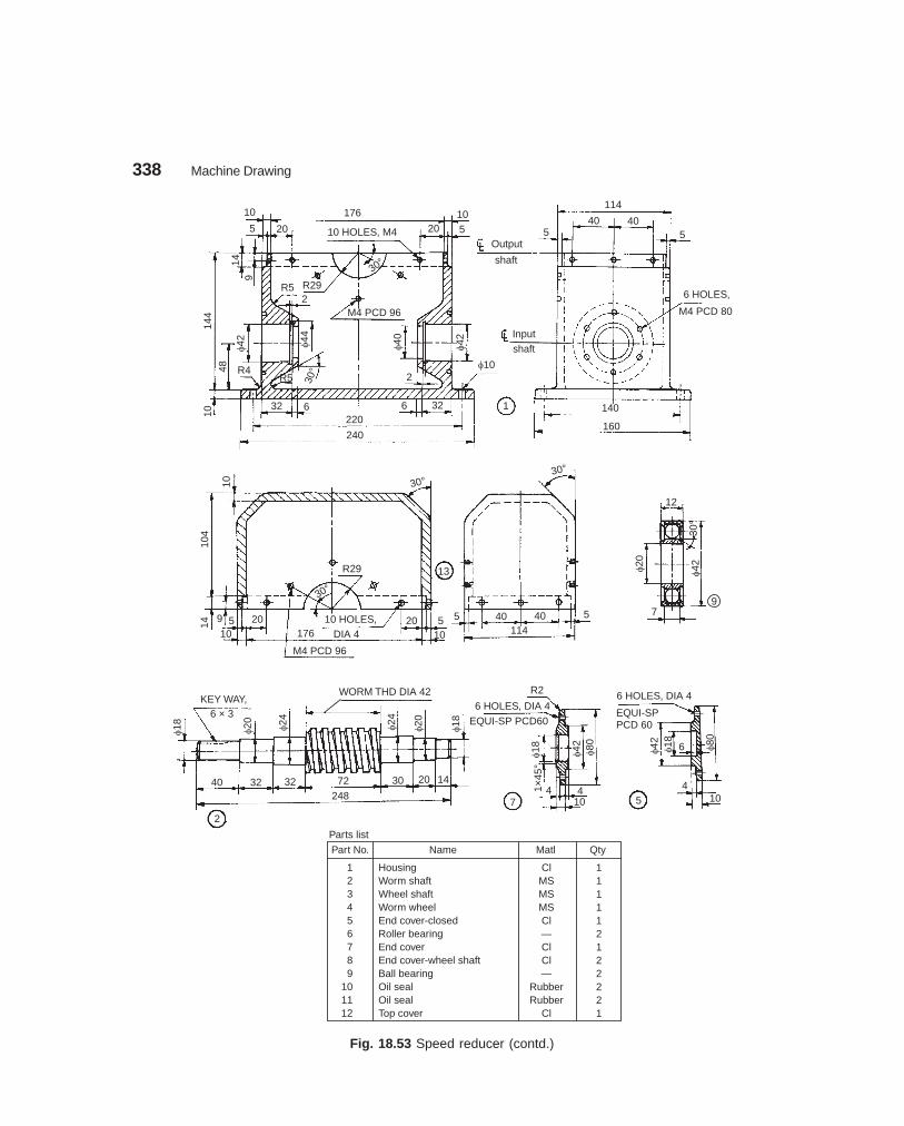
338 Machine Drawing
dharmd:\N-Design\Des18-4.pm5
Fig. 18.53 Speed reducer (contd.)
10
5 20
176
10 HOLES, M4
30°
20105
149
R5 R29
M4 PCD 96
144
48
�42
R4R5
32 6220
240
6 32�40
�42
2�10
1
Output
shaft
Inputshaft
114
40 405
6 HOLES,
M4 PCD 80
140
160
10
104
14
9 5 2010
R29
30°
10 HOLES,176 DIA 4
M4 PCD 96
20 510
5
13
30°
40 40114
5
12
30°
�20
�42
7
KEY WAY,6 × 3
�18 �20 �24
40 32 32 72 30 20 14
248
2
WORM THD DIA 42
�24
�20
�18
6 HOLES, DIA 4
EQUI-SP PCD60
R2
�18 �42 �80
1×45
°
74 4
10 5
6 HOLES, DIA 4
EQUI-SPPCD 60
�42 �18 6 �80
410
Part No. Name Matl Qty
123456789
101112
HousingWorm shaftWheel shaftWorm wheelEnd cover-closedRoller bearingEnd coverEnd cover-wheel shaftBall bearingOil sealOil sealTop cover
ClMSMSMSCl—ClCl—
RubberRubber
Cl
111112122221
Parts list
9
5
2�44
10
30°
30°

Assembly Drawings 339
dharmd:\N-Design\Des18-4.pm5
The closed end cover 5 is used on the right side of the worm shaft and fastened to the housingwhile end cover 7 is fastened to the housing on the left side.
The worm wheel 4 is fitted on the wheel shaft by means of a key. The oil seal 11 and rollerbearing 6 are assembled in both the wheel shaft end covers 8. These end cover assemblies arelocated on the wheel shaft assembly and placed over the housing. The top cover 12 is placed overthe housing and the wheel shaft end covers are fastened to both the housing and top cover, thuscompleting the assembly.
������
The details of a single stage worm gear speed reducer are shown in the Fig. 18.53. Assemble theparts and draw to a suitable scale, (i) sectional view from the front and (ii) the view from the left.
��������� ��� ������ �
The assembly drawings are very critical and the principles of making the assembly drawingsfrom the part drawings are explained in detail in the text. The preparation of assembly drawingsfrom part drawings, require lot of skill. This can be achieved only through practice.
As a guide to the students, for majority of the projects considered in this chapter, oneassembly drawing; plain or sectional, is presented. Some are included in the text itself and for theremaining ones, the views are given below. For example, Fig. 18.1A shows the assembly drawingof the components given in Fig. 18.1 and so on. The students are advised to study these views anddevelop other required ones.
5024
60 TEETHPCD 158
R5R5
KE
YW
AY,6
×2
4
8
30°
�28
�72
�11
6�28
�24
3310 19
124
�36
�48 �58
8
R26 HOLES, DIA 4EQUI-SP, PCD 96
12
�48
�24
30°
86
81×45°
�42
�20
610
KEY WAYS,
6 × 3
�24
2×45°
3
2067
�28
4076 67
�24
20 2×45°
8 1×45°
�36 �24
6 11
30°
Fig. 18.53 Speed reducer
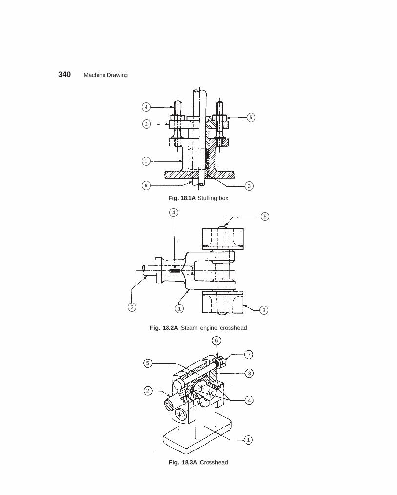
340 Machine Drawing
dharmd:\N-Design\Des18-4.pm5
4
2
1
6 3
5
Fig. 18.1A Stuffing box
54
2 1 3
Fig. 18.2A Steam engine crosshead
6
7
3
5
2
4
1
Fig. 18.3A Crosshead

Assembly Drawings 341
dharmd:\N-Design\Des18-4.pm5
1 2 3
4
Fig. 18.6A Petrol engine piston
5 8 9
10
3
1
4
6
2
7
Fig. 18.7A Radial engine sub-assembly

342 Machine Drawing
dharmd:\N-Design\Des18-4.pm5
3 4 2 1 9 7 5
8
6
Fig. 18.9A Rotary gear pump
5
4
3
2
1
6
9
8
7
9
10
4
7
6
1
3
5
2
8
Fig. 18.10A Air valve Fig. 18.11A Fuel injector

Assembly Drawings 343
dharmd:\N-Design\Des18-4.pm5
4 3 5
6
7
1
2
108 9
Fig. 18.15A Square tool post
1 3 2 4 5
6
Fig. 18.16A Clapper block
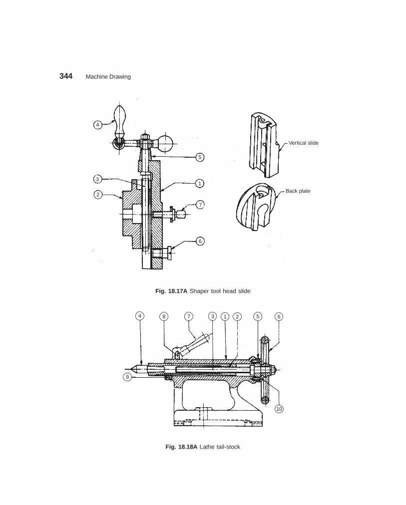
344 Machine Drawing
dharmd:\N-Design\Des18-4.pm5
4
3
2
5
1
7
6
Vertical slide
Back plate
Fig. 18.17A Shaper tool head slide
4 8 7 3 1 2 5 6
9
10
Fig. 18.18A Lathe tail-stock

Assembly Drawings 345
dharmd:\N-Design\Des18-4.pm5
3 2 8 6 7 1 4 5
Fig. 18.20A Revolving centre
2 4 876 5 10
1 3 9
Fig. 18.22A Machine vice
4 2 5 6
1
3
Fig. 18.23A Swivel machine vice

346 Machine Drawing
dharmd:\N-Design\Des18-4.pm5
8 6 9
7
3
5
2
1
4
Fig. 18.24A Drill jig
1012 6 7 13 4
2
3
11
8
1
59
Fig. 18.25A Indexing drill jig

Assembly Drawings 347
dharmd:\N-Design\Des18-4.pm5
6
8
5
3
7
3
4
1
Fig. 18.28A Gate valve
13
8
3
2
6
1
11
12
14
4
7
10
5
9
Fig. 18.29A Screw down stop valve

348 Machine Drawing
dharmd:\N-Design\Des18-4.pm5
2 5
1
4
6
3
Fig. 18.30A Non-return valve (Light duty)
3 4 6
5
1
2
Fig. 18.31A Non-return valve
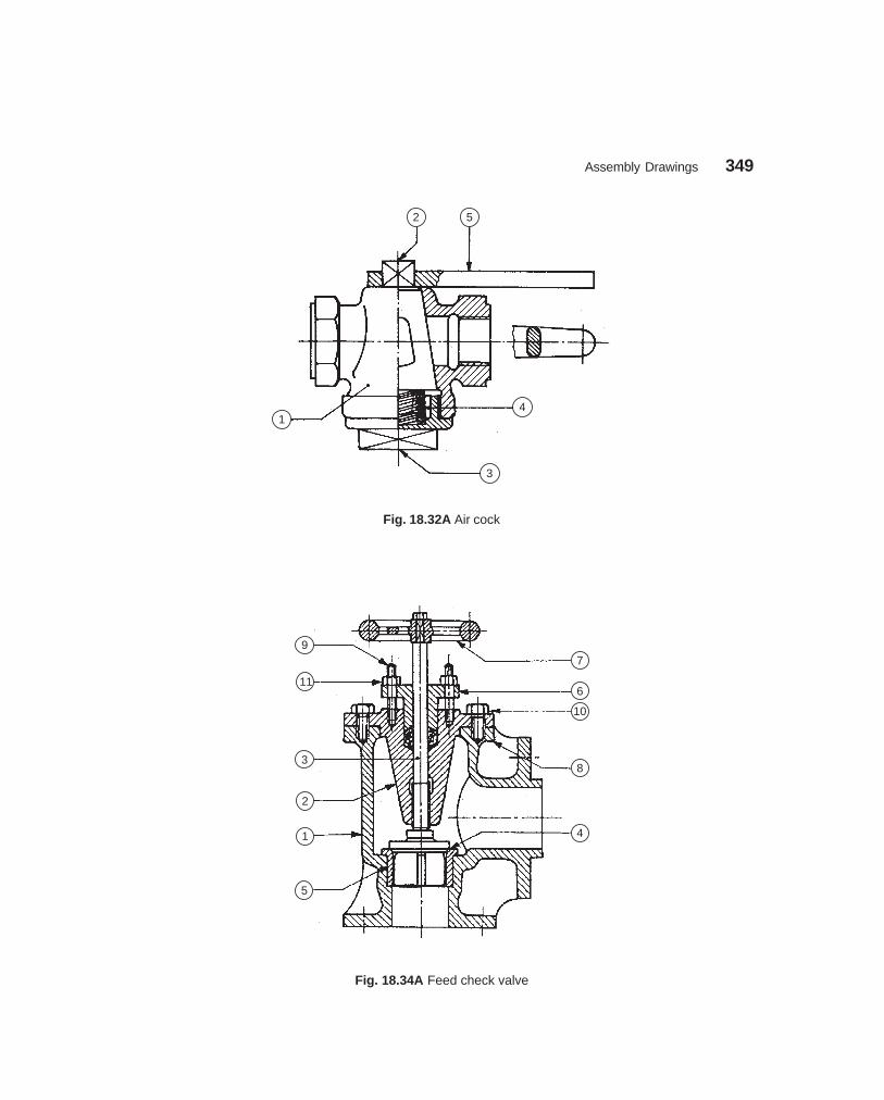
Assembly Drawings 349
dharmd:\N-Design\Des18-4.pm5
2 5
14
3
Fig. 18.32A Air cock
9
11
3
2
1
5
7
6
10
8
4
Fig. 18.34A Feed check valve
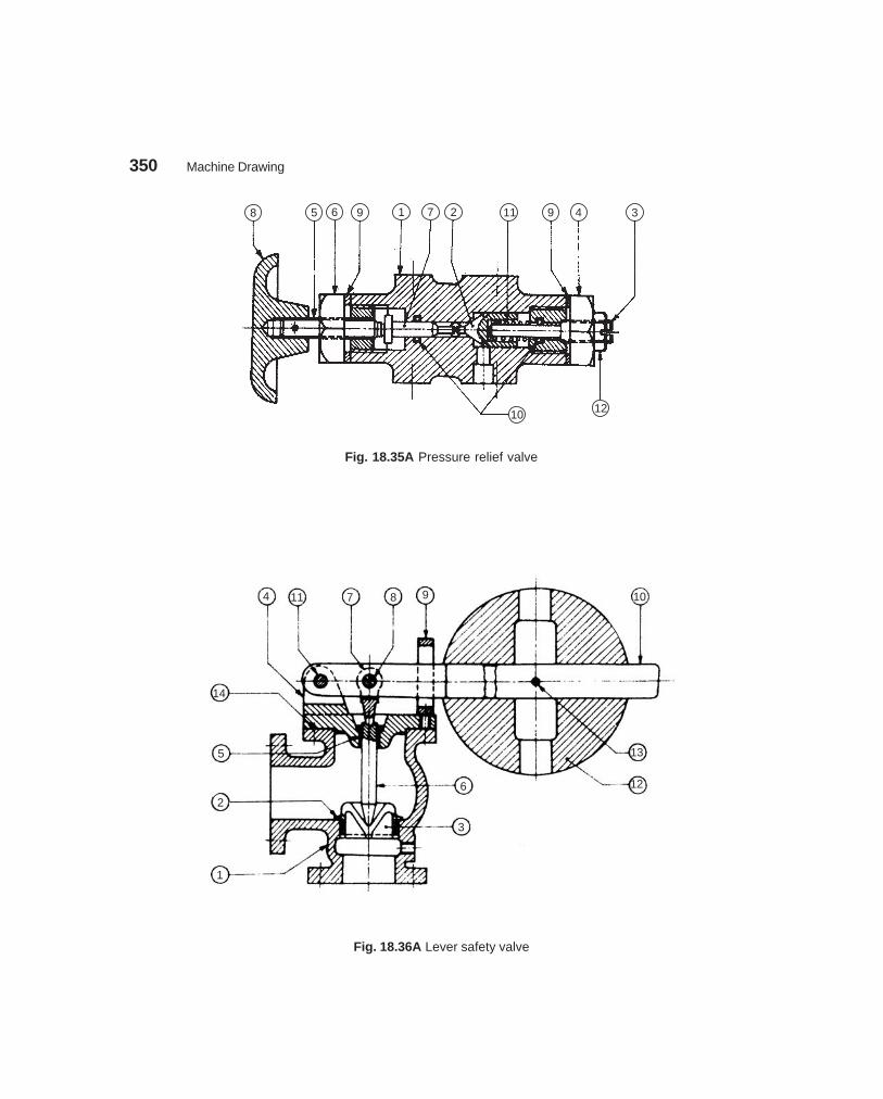
350 Machine Drawing
dharmd:\N-Design\Des18-4.pm5
8 5 6 9 1 7 2 11 9 4 3
1210
Fig. 18.35A Pressure relief valve
4 11 7 8 9
14
5
2
1
6
3
13
12
10
Fig. 18.36A Lever safety valve
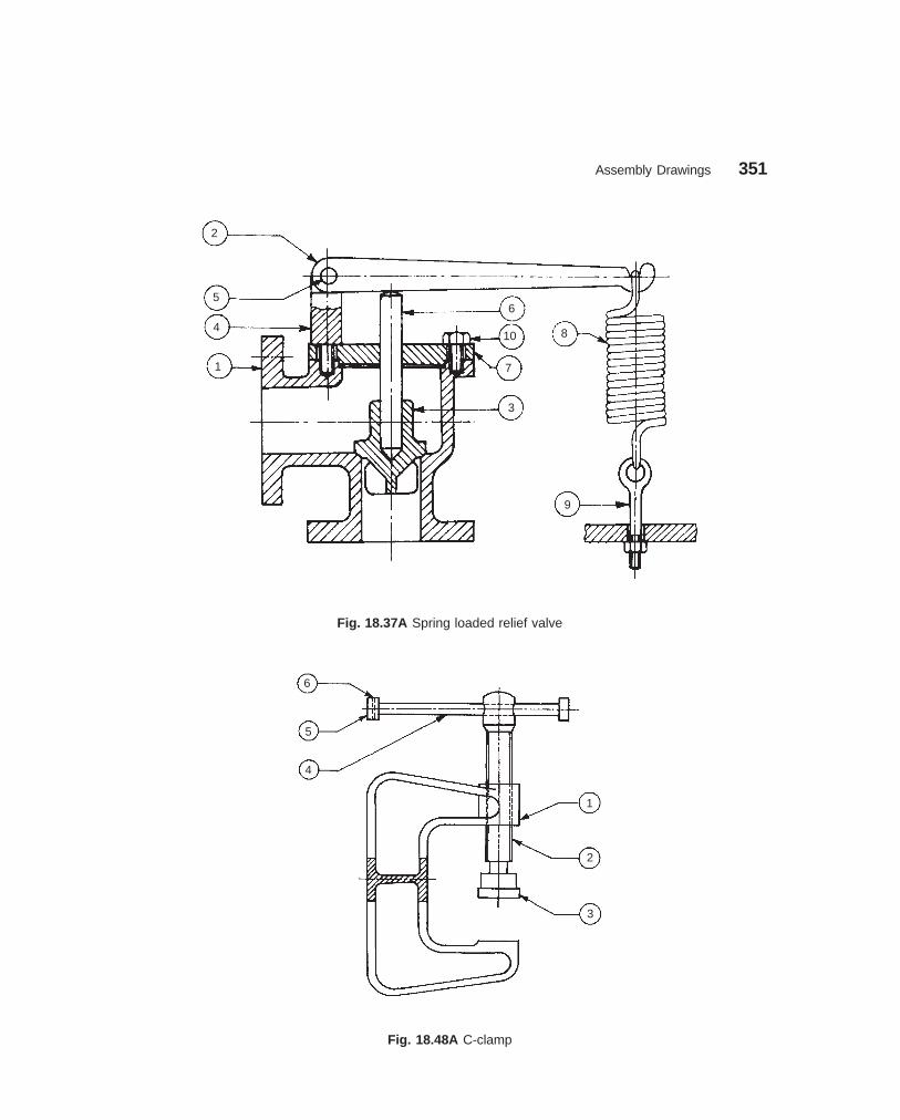
Assembly Drawings 351
dharmd:\N-Design\Des18-4.pm5
2
5
4
1
6
10
7
3
8
9
Fig. 18.37A Spring loaded relief valve
6
5
4
1
2
3
Fig. 18.48A C-clamp

352 Machine Drawing
dharmd:\N-Design\Des18-4.pm5
10
9
2
3
4
1
11
7
8
5
6
Fig. 18.49A Crane hook
6 2 4 5
1 3
Fig. 18.50A V-belt drive

Assembly Drawings 353
dharmd:\N-Design\Des18-4.pm5
6
5
4
7
3
2
1
Fig. 18.51A Screw jack
5
4
1
6
3
2
Fig. 18.52A Pipe vice
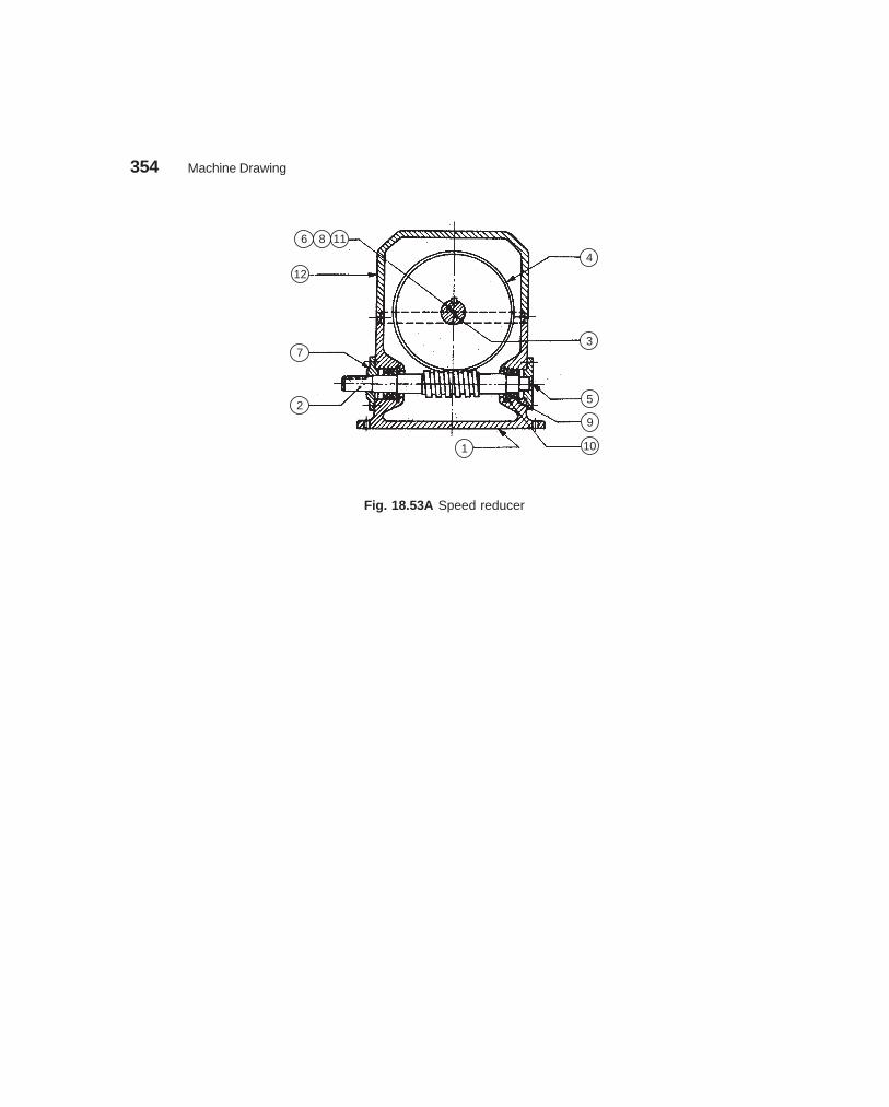
354 Machine Drawing
dharmd:\N-Design\Des18-4.pm5
1186
12
7
2
1 10
9
5
3
4
Fig. 18.53A Speed reducer

355
���� ����������
The first step in developing a new machine is the preparation of design assembly drawings. Afterthe drawing is analysed thoroughly, final assembly drawings are made from these drawings. Tofacilitate the manufacture of the unit, individual parts of the unit are to be produced first, whichrequires the preparation of part drawings. These are prepared from the final assembly drawings.The part drawing must contain all the information required such as size and shape description,dimensions, notes, suitable material, etc., to enable the student to understand the functionalaspects of the unit.
In the classroom training process, students are given final assembly drawings from whichthey are required to prepare part drawings. The assembly drawings may contain a few detailsonly, such as centre distances, locating dimensions and overall dimensions. However, the studentis expected to use the assembly drawing as a guide to prepare the part drawings. While doing so,the detailed dimensions to make part drawings can be transferred directly from the assemblydrawings, according to the scale to which they are made.
The students are expected to read the assembly drawings carefully and visualise the shapesof individual parts, before making part drawings. For this purpose, the students are advised to bethorough with the subject of blueprint reading (Chapter 17).
The steps to be followed to prepare part drawings from the assembly drawing are:1. Understand the assembly drawing thoroughly, by referring to the parts list and the
different orthographic views of the unit.2. Study the functional aspect of the unit as a whole. This will enable to understand the
arrangement of the parts.3. Visualise the size and shape of the individual components.4. As far as possible, choose full scale for the drawing. Small parts and complicated shapes
may require the use of enlarged scales so that their presentation will have a balancedappearance.
5. Select the minimum number of views required for describing each part completely. Theview from the front selected must provide maximum information of the part.
6. The undermentioned sequence may be followed for preparing different views of eachpart :
(i) Draw the main centre lines and make outline blocks, using the overall dimensionsof the views.
(ii) Draw the main circles and arcs of the circles.
19� ���� �����
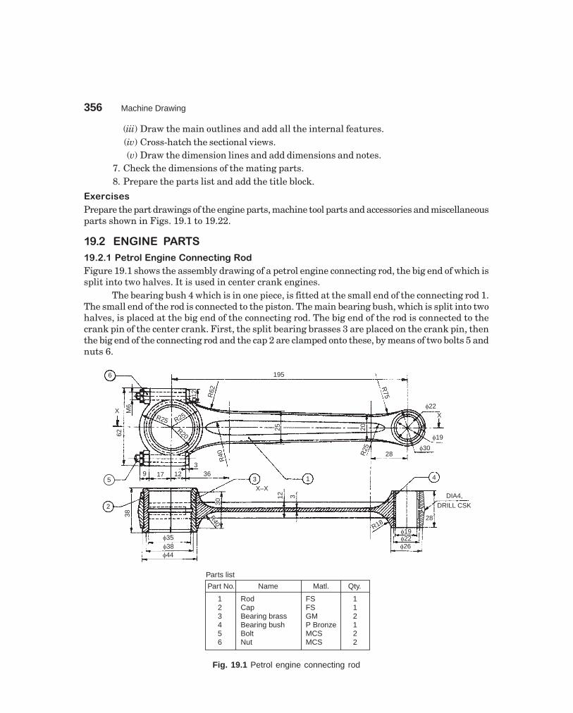
356 Machine Drawing
dharmd:\N-Design\Des19-1.pm5
(iii) Draw the main outlines and add all the internal features.(iv) Cross-hatch the sectional views.(v) Draw the dimension lines and add dimensions and notes.
7. Check the dimensions of the mating parts.8. Prepare the parts list and add the title block.
���������
Prepare the part drawings of the engine parts, machine tool parts and accessories and miscellaneousparts shown in Figs. 19.1 to 19.22.
��� � �� �� �����
��������������������������������
Figure 19.1 shows the assembly drawing of a petrol engine connecting rod, the big end of which issplit into two halves. It is used in center crank engines.
The bearing bush 4 which is in one piece, is fitted at the small end of the connecting rod 1.The small end of the rod is connected to the piston. The main bearing bush, which is split into twohalves, is placed at the big end of the connecting rod. The big end of the rod is connected to thecrank pin of the center crank. First, the split bearing brasses 3 are placed on the crank pin, thenthe big end of the connecting rod and the cap 2 are clamped onto these, by means of two bolts 5 andnuts 6.
6
X
62
M6
12 R62
R25 R25
R20
195
R75
�22X
�19
�3028R
252025
5
2
9 17 123
36
R40
38
�35�38�44
R40
R40
30
3 1
X–X
12 3
4
DIA4,
DRILL CSK
R18�19�22�26
Parts list
Part No. Name Matl. Qty.
123456
RodCapBearing brassBearing bushBoltNut
FSFSGMP BronzeMCSMCS
112122
28
Fig. 19.1 Petrol engine connecting rod

Part Drawings 357
dharmd:\N-Design\Des19-1.pm5
The bearing brasses are made of gun-metal, because it has good resistance to corrosion. Oilgroove is provided at the centre of the bearing. The bearing bush is made of phosphor bronze toprovide low coefficient of friction. Oil groove is provided in this bush for lubrication between thepin and bearing.
������������������������������������
Marine engines are generally of slow-speed and high-power type. As such, all parts of a marineengine have to be sturdy and strong.
Figure 19.2 shows the assembly drawing of a big end of a marine engine connecting rod. Itmainly consists of a rod, a bearing in two halves, a cover plate and bolts. In the case of petrolengine, one half of the bearing is an integral part of the connecting rod, whereas in a marineengine, the bearing halves are separate components to facilitate assembly of the heavy parts ofthe connecting rod.
After the two halves of the bearing brasses 3 have been placed around the crank pin, thecover plate 2 is placed in position and then all these are fastened to the rod end 1 by means of bolts4 and nuts 5. Two snugs 7, one on each bolt, are provided to prevent rotation of the bolts. Splitcotters 6 are used as locking devices for the bolts.
�����������������������������������
In a steam engine, connecting rod is used for connecting the crank with the crosshead. It may beof rectangular or circular in cross-section. The two ends of the rod are referred to as big end andsmall end.
Figure 19.3 shows one particular design of a big end of a steam engine connecting rod,connected to the crank with the help of the strap 3. The end of the connecting rod 1 is forged to arectangular section and the brasses 2 are carried by the strap. The strap and the rod end arefastened to each other by means of a gib 4 and a cotter 5. The cotter has a taper on one side onlyand is prevented from slackening by the set-screw 6.
�� ��!��"���#�
In a petrol engine, fuel under high pressure is ignited by producing intense sparks by means of aspark plug. Figure 19.4 shows an assembly drawing of a spark plug with various parts indicated.In this, the central electrode 3 is screwed into the insulator 2. The insulator is fitted into the shell1 by means of a nut 4 and is made gas tight in the shell by lower 7 and upper 8 sealing gasketsrespectively. The upper end of the central electrode is threaded to receive the plug terminal 6. Thehigh tension (HT) cable connector is fitted to this terminal.
The lower end of the central electrode extends slightly beyond the bottom surface of theshell. Ground electrode 5 is welded to the bottom face of the shell 1. The ground electrode is bentover at right angle so that a spark gap is formed between the two electrodes.
��$�������������������%���
The crosshead in a steam engine, acts as a link between piston rod on one side and connecting rodon the other. Figure 19.5 shows the assembly drawing of a steam engine crosshead. It consists ofthe shoes 2 which are fitted into the crosshead body 1, using the circular projections provided inthe shoes. The shoes are confined to move along the guides provided in the engine frame.
The piston rod is connected to the body by means of the cotter 7. The connecting rod (notshown in the figure) is connected to the crosshead by a pin joint. The bearing 3 is in two piecesand the wedge block 4 and the bolt and nut assembly 5 are used for bearing adjustment.

358 Machine Drawing
dharmd:\N-Design\Des19-1.pm5
Fig. 19.2 Marine engine connecting rod end
1 �40
15
�19
0
�80
9�48
9
270
8 2 7
12
8M10
�72
36 36 50 52 52 50 364
516 121012 16
3
R142
R130
162
70 18
680 80
10
90 118
11
10 R56
R76R56
Part No. Name Matl. Qty.
12345678
Rod endCover endBearing brassBolt M54 × 360Nut, M54CotterSnugLeather packing
FSFSGMMS
MCSMCSMS
1122222
Parts list
46

Part Drawings 359
dharmd:\N-Design\Des19-1.pm5
Fig. 19.3 Steam engine connecting rod end
5
4
1
20
2022
1:25
50
56 3
32
256
38
75
R25
10 105
503
R
20
OIL HOLE,
DIA 3, CSK DIA 6
3
16
10
6
�55
3
100
13
10
2
Part No. Name Matl. Qty.
123456
Connecting rodBrassesStrapJibCotterSet-screw
FSGMMSMS
MCSMCS
121111
Parts list
32
M10M10
�50

360 Machine Drawing
dharmd:\N-Design\Des19-1.pm5
Fig. 19.4 Spark plug
�10
�8
M5
6
66
31.
5
245
54
�8
�10
�15�12
�22�24�21
�18
187.
512
.5
2
4
8
518
27
88
10 1.5
�33
8
112
�20
M36 13
3×45
°
55
118
24
7
5
6
1.5
14 WIDE 4�3
�5
�10
�16
�26
M30
�43
3
Part No. Name Matl. Qty.
12345678
ShellInsulatorCentral electrodeNutGround electrodeTerminalSealing gasketSealing gasket
MCSPorcelain
NickelMCSNickelBrassAsbe-stos
11111111
Parts list

Part Drawings 361
dharmd:\N-Design\Des19-1.pm5
Fig. 19.5 Steam engine crosshead
OIL HOLE,DIA 6 CSK
12228
24
30 42
2411
4
6 168
2121
24
50 �21
R8
18
78 132
210
1
4
30R40 �54
503
M21
50
�18
321
9
30
36
�6
78 60
66
40
32R24
7
2
3
5
12
12
104
R35
�54
�45
�78
12
�42 60
78
144
78 102
Part No. Name Matl. Qty.
1234567
Crosshead bodyShoeBearingWedge blockBolt and nutPistonCotter
WICI
GMMS
MCSFS
MCS
1211111
Parts list
12
Oil
hole

362 Machine Drawing
dharmd:\N-Design\Des19-1.pm5
��&��#����'���������(��
��������� ���� ����
The top speed of a car depends upon the maximum power of its engine, and this is developed nearthe engine’s maximum power. A typical car engine may run at 4000 rpm for a top speed of 110kmh. But road wheels of average size turn at only about 1000 rpm to cover 100 km in an hour. So,they cannot be connected directly to the engine. There must be a system which allows the roadwheels to make one revolution for every four of the engine. This is done by a reduction gear in thefinal drive (differential).
The relation between the rotational speed of the engine and the wheels is the axle ratio; 4:1being common. As long as the car is driven at a steady speed on the level, this gearing is sufficientbut when the car meets a hill, its speed will drop and the engine will falter and stall. A slow-running engine cannot provide enough torque for climbing hills or starting from rest. Selecting alower gear enables the engine to run faster in relation to the road wheels and also multiplies thetorque.������������������
The lowest gear in the gear box must multiply the engine torque sufficiently to start the fullyladen car moving up a steep hill. A small car needs a lower gear ratio of 3.5:1. Other typical gearratios in a small car with a four-speed gear box are 2:1 in second, 1.4:1 in third and 1:1 in topgear. All these are multiplied by the axle ratio, so that, if the axle ratio is 4:1, the correspondingratios between the engine speed and the road wheel speed are 14:1, 8:1, 5.6:1 and 4:1.
��������������������
The gear box shown in Fig. 19.6 is a constant-mesh type in which all the gear wheels cannot befixed to their shafts. There has to be a system which permits all the gear wheels except thoserequired for a particular ratio, to run freely. Usually, all the gear wheels on one shaft are fixed toit and the wheels on the other shaft can revolve freely around their shaft until a ratio is selected.Then, one of the free-running wheels is locked to the shaft, and that pair of wheels can transmitpower.
Transmission gears are made of high quality steel, carefully heat-treated to produce smooth,hard surface gear teeth with a softer but very tough interior. They are usually drop-forged. Theteeth on transmission gears are of two principal types: spur and helical. The helical gear issuperior in that it turns more quietly and is stronger because more tooth area is in contact.
The locking of the gear wheels to a shaft is done by collars, which are splined to the shaft.This method of fixing, allows the collar to revolve with the shaft and also slide along, to lock ontothe gear wheel on either side, or remain between them, allowing both to spin freely.
Around each collar, is a groove engaged by a two-pronged fork which is fixed to a sliding rodmounted in the gear box housing. One, two or three of these selector rods are linked to the gearlever. Moving the gear lever causes selector rod to slide to or fro. As it slides, the collar gripped bythe selector fork is slid along the shaft to engage with, or move away from, a gear.
����������������������������������������
In the simplest type of constant mesh gear box shown, the gears may be engaged simply byshifting the gear lever from one position to the next as fast as possible. To do the job more quietlyand smoothly, the pair of dogs had to be allowed to reach the same speed, so that they would slidetogether without clashing.
Drivers today are relieved from the need for double de-clutching for change of speeds by asynchronising device built into the sliding collars in the gear box. This synchromesh device isusually fitted to all forward gears. Synchromesh works like a friction clutch. It has a collar which

Part Drawings 363
dharmd:\N-Design\Des19-1.pm5
is in two main parts. A sleeve with internal cones [Fig. 19.6 (c)] slides inside the toothed outerring, which forms the dogs to match the gear wheel cones with the parts rotating at the samespeed. The spring loaded outer ring of the collar is pushed forward for the dogs to mesh.
When the collar is pushed towards the gear wheel with which it is to mesh, a conical ringon the gear wheel in front of the dogs comes into contact with the surface of a matching conicalhole in the collar. The friction between the conical surfaces, brings the free-running gear wheelup or down to the speed of the output shaft. The collar continues to move along and the pair of dogsslide smoothly into mesh. However, if the gear lever is moved too fast, the gears will clash.
A typical automobile gear box consists of a cast iron or an aluminium housing, four shafts,bearings, gears, synchronising device and a shifting mechanism. Figure 19.6 shows the assemblyof such a gear box, partially sectioned. This gear box provides four forwardes speeds of the ratios4:1, 2.4:1, 1.4:1 and 1:1 and a reverse speed.
���������� �!���
Figure 19.6 (a) shows the gear box in its neutral position. The housing 1 is made of aluminiumalloy and a supporting plate 2 is fixed to it for supporting the reverse gear shaft 5 at one end; theother end being located in the rib provided inside the housing. The input shaft 3 is supported by aball bearing 7. One end of the output shaft is supported by a ball bearing, while the other end islocated with free running fit, inside the bore (φ 15) provided at the inner end of the input shaft. Theintermediate shaft 4 is supported both sides by the ball bearings.
The gears B, C and E are keyed in position on the intermediate shaft. The gear G isintegral with the shaft. The gear A is keyed onto the input shaft. The gears D and F are constantlyin mesh with the gears C and E but free to rotate on the output shaft when not engaged. The gearH is integral with the toothed ring 8 and slides on the sleeve 11 when operated by the fork 14. Thesleeve 11 is splined to the output shaft and has external splines also on which the toothed ring 8along with gear H slides on a single collar.
Similarly, the sleeve 10 is splined to the output shaft at its inner end, on which is fixed thetoothed ring 9 with internal splines and slides over the sleeve when operated by the fork 13. Threespring loaded balls 12 are provided between the sleeve and the ring to keep them together as asingle collar during free running and also when engaged with the toothed dogs [Fig. 19.6 (c)]. Thebushes 15 act as bearings for the reverse gear shaft.
When the input shaft rotates, power is transmitted to the intermediate shaft continuouslythrough the herring-bone gears A and B. Now, depending on the position of the forks 13 and 14and the corresponding collars, different speeds are obtained. When the fork 13 is in neutralposition and fork 14 is moved until the spur gear H engages with G, then, due to two stepreduction of speed, the lower speed ratio 4:1 is obtained at the output shaft. To obtain the secondgear, the fork 14 is moved to the left until the collar completes the meshing and engages with thedog teeth. This operation arrests the independent free rotation of gear F, by engaging the dogteeth with the toothed ring, and the output shaft through the sleeve which is splined on it. Thegear E on the intermediate shaft transmits power to the output shaft through gear F which is thesecond gear with a ratio 2.4:1.
To obtain the third gear, the gears in mesh are A-B, and C-D with the collar consisting ofsleeve 10 and toothed ring 9 engaged with dog teeth on gear D; the speed ratio being 1.4:1. Whenthe toothed ring 9 engages with the dog teeth on gear wheel A, mounted on input shaft, thetransmission is established directly to the output shaft; resulting in top speed ratio of 1:1.

364M
achine Draw
ing
dharmd:\N
-Design\D
es19-1.pm5
Fig. 19.6 Automobile gear box (contd.)
13 D F H 14 8
11
1
7
6
12
2
15
5
I
3
A
10
9
4
B34T
68.7
5
21T
KE
YW
AY,6
×4 TEETH ON DOG,
24 × 50 × 5818
26T TEETH ON
DOG 30×58×66
SPLINES
24×50×58
33T
39T
�97.
5
8
SP
LIN
ES
30×
58×
66
19
203 5
�80
10
�66
�28
�52.
5
15
�15 25
17
�62
SPLINES, 6×28×20
�65
2
20
�40
�82.
5
2 5
1035°
�73
�85
4 6
45
50
�28
3NO’s AT 120°
10 9 7
75
8 18
15
�52.
5
�25
�85
�55
�40 �2
5
�12
�18
20 18SPLINES,
6 × 28 × 20
145
186
(a)
18 �72.
5
20
20
10 15 18
35 10
29T 22TC E
16TG
21T
8
10
7
�25
�20
�42
�42 �1
5
�25
�25

Part D
rawings
365
dharmd:\N
-Design\D
es19-1.pm5
Fig. 19.6 Automobile gear box
H
G I
(b)
9
10
6
12
Spring loaded ball hold thecollar together
Pressure on the gear levercauses toothed outer ringto slide into engagement
Part No. Name Matl. Qty.
123456789
101112131415
HousingShaft supportInput shaftIntermediate shaftReverse gear shaftOutput shaftBall bearing 6205Toothed ringToothed ringSleeveSleeveSpring loaded ballForkForkBush
Al alloyAl alloyMCSMCSMCSMCS
—MCSMCSMCSMCS
—Forged steelForged steel
Bronze
Forged steel
Forged steel—
111111411116112
A, B, C, D, E, and FHerring bone gears
H and I, Spur gearsG, Spur gear
All gears, module 2.5 mm
Parts List
(c)

366 Machine Drawing
dharmd:\N-Design\Des19-1.pm5
The reverse gear is obtained through the gears A-B, G-I and J-H. The gear I is of largerwidth mounted at the rear of the gear box and it acts as an idler to reverse the direction of theoutput shaft. The position of these gears is shown in Fig. 19.6 (b).
��)��!���*�%��+�����������
Figure 19.7 shows the assembly drawing of a split-sheave eccentric. In this, sheaves 1 and 2,forming a circular disc with a stepped rim is housed in two abutting straps 6 and 7. Two shims 8are used in-between the straps for free movement of the sheave. When the shaft rotates, thesheave rotates eccentrically, imparting reciprocating motion to the eccentric rod. The eccentricrod is connected to one of the straps rigidly.
The straps are semi-circular elements, with an annular recess to accommodate the steppedrim of the sheave. The rotary motion of the sheave is converted into linear motion to the eccentricrod, through the straps. These are held together on the sheave by means of strap bolts, withpacking strips placed between them. These permit adjustment for wear at a later date. Theeccentric rod is connected to one of the straps by means of studs 11.
��� ���,� �� �--.� ������ � /� ������-����
�������������
Tool posts of various designs are available to support the cutting tools in lathe machines. Figure19.8 shows the assembly drawing of a single tool post which supports one cutting tool and is usedon small size lathes. This unit is fixed on the compound rest of the lathe carriage.
The body of the tool post is in the form of a circular pillar 1 with a collar at one end and athreaded hole at the other end. A vertical slot is also provided to accommodate the tool or toolholder. The pillar is slid through a square block 5, which finally is located in the T-slot, providedin the compound rest. The design permits swivelling of the pillar about its vertical axis. A circularring 4 is slid over the pillar and wedge 3 is located in the vertical slot of the pillar. The tool or toolholder is placed over the wedge. By sliding the wedge on the spherical surfaced ring, the tool tipcan be finally adjusted and clamped in position by means of a square headed clamping screw 2,through the pillar head.
����.��%������������
This is used for holding and guiding the cutting tool on the lathe machine. It is fixed on the lathecarriage. The lathe slide rest has a circular base with a cylindrical projection underneath. It isfixed to the carriage by means of two bolts. The projection enables the slide rest to be fixed at anyangle with respect to the axis of the work.
Figure 19.9 shows the assembly of a lathe slide rest. The upper face of the body 1 haschannel shaped section and machined to act as guides for the slide block 2. The slide block hasa T-slot on the upper side for accommodating the tool holder 3. The bottom of the slide blockis machined to form a guide way on one side and takes a wearing strip 5 for the purpose ofsliding.

Part Drawings 367
dharmd:\N-Design\Des19-1.pm5
15
3655
0
88
45°
100
R270
6
8
9
3
1
�47
10 4 5
R24 �45
24 100 10012
6
4180
5 25R220R100
R130
25 R18
550
50° 30
R270R30
R180
754
7
11
4
16 30
200 �7
5
�60
M14R40
20 26 38
2
12
�75
150
230
Part No. Name Matl. Qty.
123456
Sheave pieceSheave pieceBolt M30 × 135Nut M30Split pin 6 × 50Strap
�
CSCSMSMSMSCl
112661
Part No. Name Matl. Qty.
789
101112
StrapShimBolt M30 × 250Lock nut M30Stud M30Washer
ClBrassMSMSMSMS
122222
Parts list
R230
Fig. 19.7 Split-sheave eccentric
A circular hole is provided at the centre of the block for holding the cylindrical portion ofthe nut 4. An adjusting screw 8 passes through the nut and is held to the body by means of abearing plate 6.
By operating the adjusting screw, the slide block is made to move along with the tool holderon the body. A cylindrical tool holder 3 is fitted in the T-slot provided on the slide block. A tool isfixed in the tool holder by means of a screw 9. A circular washer 7 is provided on the slide blockwhich forms a bearing surface for the cutting tool.

368 Machine Drawing
dharmd:\N-Design\Des19-1.pm5
15 2
U/C WIDE 5
DEEP 2
�32
�36
�50
120
1
R14
5
16
76�100
4
3
5
1312
96
8
615
�28
M22
12
�15
18
R145
106
146
�51
�62
9
SERRATED
Part No. Name Matl. Qty.
12345
BodyClamp screwWedgeRingSquare block
MSMCS
CIMSMS
11111
Parts list
Fig. 19.8 Single tool post
����.��%���!���������(��
In a conventional engine lathe, different spindle speeds are obtained by means of belt driven conepulley and back gear arrangement. The step cone pulley and the back gear are accommodated inthe headstock of the engine lathe. This arrangement suffers from (i) slipping of the belt, (ii)change of speed, requiring change of belt position and (iii) lack of positive drive. To overcome thesedraw backs and to provide a positive drive, the belt drive is replaced by a gear drive. A lathe withspeed gear box is known as an all geared lathe. The assembly drawing of an all geared latheheadstock is shown in Fig. 19.10(a). It may be noted that, for the purpose of clarity of the drivemechanism, the shafts are shown as if they are one below the other and in the same plane.
The drive shaft S2 is positioned in the head stock body 1 of the lathe and is driven by anelectric motor through a belt drive, using a V-pulley 5. The headstock also contains an intermediatesplined shaft S3, on which sliding gears are mounted. Further, spindle S4 is also positioned in thehead stock on which work holding devices such as self centering chuck, etc., are attached. Thespindle is mounted on the taper roller bearings 6 and 7, which resist both axial thrust as well astransverse or radial force coming on the spindle. The drive shaft and the intermediate shafts aremounted on the ball bearings 8, 9 and 10. These bearings are protected by means of the cover

Part Drawings 369
dharmd:\N-Design\Des19-1.pm5
plates 11, 12, 13, 14 and 15 which are held in position by the round headed machine screws19 and 20. A live center 17 is mounted in the spindle by means of reduction sleeve 16.
1676
M16×2
�32
�38
32
3
2
�75186
6610
SQ THD 16×4 LH2 OIL HOLES DIA 3
25 �21 3 25 13
35
11
19 16 198 45
�2238
15 �16 1111 11
116
1910
32
�38143�120187
16
3
1
6 8
16 44 16
2 OVAL HOLES,8 × 5
987
38 288
5
1758
4
36
14
58°
1434
18 1829
2929 18
18
1818
36
4141
10
2 HOLES, DIA15
Part No. Name Matl. Qty.
123456789
10
BodySlide blockTool holderNutWearing stripBearing plateWasherAdjusting screwScrewMachine screw
ClClMSMSMSMSMSMSMSMS
1111111112
Parts list
9
19
RR
22
10
3266
�12
Fig. 19.9 Lathe slide rest
The spur gears A, B and H are keyed on the drive shaft, whereas the gear G is an integralpart of the shaft. A compound gear sleeve, consisting of gears D and E is mounted on the inter-mediate splined shaft to which are keyed the gears C and F. All the gears from A to H are of thesame module, 2.5 mm. The compound gear I and J of module 3 mm are also mounted on theintermediate shaft. Compound gears K and L of module 3 mm are fixed to the spindle.
For obtaining different spindle speeds, the gear sleeve consisting of the gears C, D, E and Fis moved on the spline shaft by lever X and the compound gears I and J by the lever Y. Thefollowing gear engagement provides 8 different speeds for the spindle:

370 Machine Drawing
dharmd:\N-Design\Des19-1.pm5
1. A-C-I-K 5. A-C-J-L2. B-D-I-K 6. B-D-J-L3. G-E-I-K 7. G-E-J-L4. H-F-I-K 8. H-F-J-LFor providing drive to the feed gear box from the spindle, gear M of module 2 mm is rigidly
fixed to the spindle.Figure 19.10(b) shows the isometric view of the headstock body and both the side views.
The details of the bearing cover plates are indicated in the side views.
�� ������������%�������������"
Certain jobs requiring milling operations, in relation to their axes of rotation, are usually supportedbetween centers. An assembly drawing of a milling machine tail-stock is shown in Fig. 19.11. Thejob is held between the centre in the dividing head and adjustable center provided in the tail-stock. This is similar to the lathe tail-stock.
To fix the work between centers, the dividing head spindle is first brought to a horizontalposition. Then, one end of the work is supported in the work center of the dividing head spindle,with the help of a mill-dog. The tail-stock position is then adjusted to suit the length of the workand it is then clamped to the table of the machine, in that position. After clamping of the tail-stock, fine adjustment can be made by rotating the knurled hand wheel 3. The knurled handwheel is attached to the center by the screw 4, washer 6 and nut 7. This will allow tail-stockcenter 2 to slide horizontally in its guide. After setting correctly, the center is clamped by meansof screw 5.
Unlike the lathe tail-stock, there is no relative motion between the center and the workpiece in the milling machine tail-stock; hence the center may be made of mild steel.
��$�.��%�����+�����������
It is an attachment to a lathe machine for supporting long slender work pieces against the cuttingtool forces. Figure 19.12 shows an assembly drawing of a lathe travelling rest. The design permitsit to be clamped to the carriage of the lathe, enabling it to travel along with the cutting tool. Thetwo jaws 2 are positioned slightly behind the cutting tool, so that the bearing is taken on theround portion of the job, which has been just finished. The two supporting jaws of the rest, resistthe cutting forces. Jaws may be adjusted by the hexagonal headed screws 3 and clamped inposition in the main body 1 by means of set-screws 4. A flat surface is provided on the jaws, foreffective clamping. A guide strip 5 is used for the proper adjustment of the travelling rest on theguide ways of the carriage. To reduce the damage to the finished surface of the job, the jaws arenormally made of brass.
��&����0*����������1���
Figure 19.13 shows the assembly drawing of a self-centering vice. This is used as a quick actingfixture for locating and holding circular shafts and work pieces for cutting keyways, grooves,slots, etc. The vice consists of a CI body 1 into which a V-block 4 may be fitted tightly. Based onthe size of the workpiece, the size of the V-block is chosen. Two CI jaws 2 are fitted to the bodywith the help of pins and the pins provide swivelling action to the jaws, to clamp the workpieceonto the V-block.
Two cylindrical nuts 7 and 8 are located on the other ends of the jaws. A right hand screw5 engages the nut 7 and the screw has a collar at the other end. A left hand screw 6 is fitted in thecollar and engages the nut 8. The handle 9 is fixed to the other end of the screw 6 by means of thetaper pin.
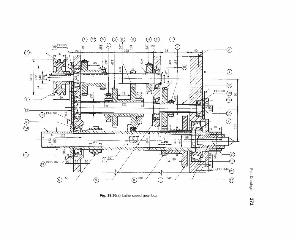
Part D
rawings
371
dharmd:\N
-Design\D
es19-1.pm5
Fig. 19.10(a) Lathe speed gear box
11
19
A S2 B
C
D E G H 8 I
J20
18
1
S3
19
14
10
7
17
15
20
16
5
12
19
6
S4
13
19
M
F
9 K L
�110
�72
�40
�20
36
R46
�25
40 33T
47T
�30
Key
Key
24
39T
25T
54T
228
18T
33T 20
93 40
16T
40T
50
PCD 90
R54
125
�42
�50
R60
PCD 102 10 25 10
50 T
39T
6
�30
40X
�60
�78
�40
95
�70
50
30T 54T
10 PCD144
R80
M60
40 105
90
6 PCD 60
R32
�20
�25
42
122
�36
�25
Y
PCD75

372 Machine Drawing
dharmd:\N-Design\Des19-1.pm5
Fig. 19.10 (b) Lathe speed gear box casing—(i) Isometric view,(ii) View from the right, (iii) View from the left.
(i)
S4
15
14
(ii)
S3
12
11
S2 S4
13
1S3
102 58
7544 80
65
120
46
(iii)
Part No. Name Matl. Qty.
1S2S3S4
56789
101112
BodyDrive shaftIntermediate shaftSpindlePulleyTaper roller bearing (32211)Taper roller bearing (32214)Ball bearing 6005Ball bearing 6006Ball bearing 6004Cover plateCover plate
ClMSMS
MCSCl
ClCl
111111122111
Part No. Name Matl. Qty.
1314151617181920
Cover plateCover plateCover plateReduction sleeveLive centreCirclipRound HD SCR M5×15Round HD SCR M5×20A to H spur gears module 2.5I to L spur gears module 3M spur gear module 2
ClClCl
MCSHCS
MSMS
MCSMCSMCS
111111
124841
Parts list
200

Part Drawings 373
dharmd:\N-Design\Des19-1.pm5
Fig. 19.11 Milling machine tail-stock
R3066
3
35 M12
�28
�28
R15
125
25
�40�40
30150
610
18
5 2
60°
180100
3635
14 18
�25
60 9 12
�28
�28
�80
R125
6
7
3
1
18
�18150
4
Parts list
Part No. Name Matl. Qty.
12
34567
BodyCentre
Hand wheelScrewScrewWasherNut
ClCase hardened
alloy steelCast steel
MSMSMSMS
11
11111
�30
M15

374 Machine Drawing
dharmd:\N-Design\Des19-1.pm5
Fig. 19.12 Lathe travelling rest
X
4
M12
10 48 �54
240
42 30
12
48
X
130
24
12
3624
3678
18
5102
252
10°X–X
R115
R72 108
M15 12 �2
4
12
�12
48727212
2
3
R200
33 33120
Part No. Name Matl. Qty.
12345
BodyJawScrewScrewGuide strip
CIBrassMCSMCSMS
12221
Parts list

Part D
rawings
375
dharmd:\N
-Design\D
es19-1.pm5
Fig. 19.13 Self-centering vice
104
OIL NIPPLE
5
70X–X
24
5
322020
6 16 14 24 1482 16
15
�26
�34
322
2 HOLES, M6FOR TENONS
7
5
10
1
4
11
2
336
226
16 R110
�5090°54
10
1430
�20
7530
42SQ
THD
DIA
61R
H
10124
12
90° 16 28
46
�30
25
�30
12
2556
112
�22
40 156 R26
CSK SCR
�40
R10
15
16 10
WEB 3 NO.
�28
�15
�28
36 80
8
6
4060
6040
102
R10
40
18
R6
Part No. Name Matl. Qty.
123456789
1011
BodyJawJaw plateV-BlockScrewScrew, LHNut (cylindrical)Nut, LH (cylindrical)HandleLocating pinPin
CICIMSMSMSMSMSMSCIMSMS
12211111112
Parts list
1410
X
9
X
DIA 5
Tape
rpi
n
SQ
TH
DD
IA16
LH
64
376 Machine Drawing
dharmd:\N-Design\Des19-1.pm5
When the handle is operated, the two jaws are moved towards or away from the V-block, byturn-buckle principle. However, to ensure positive movement of the jaws, the translatory movementof the screws 5 and 6 is arrested by means of locating pin 10; the square head of which fits into thecorresponding groove in the collar of the screw. Two tenons (not shown) are fitted to the base ofthe body to ensure proper alignment of the vice axis with respect to the machine spindle axis.
��)���������2���#��
Figure 19.14 shows a simple milling fixture. The fixture is located on the machine table by twotenons 7 and clamped to the machine table in the T-slots. The workpiece is located using the fulldiameter locating pin 8 and flattened locating pin 4. The job is clamped by two heavy duty clamps2 to the fixture base.
The cutter setting is obtained by using the setting block 3, for both depth and transversesetting. The setting block is fixed by means of locating pins 9 and dowel pins 10. The clamps arepositioned by guide pin 11 and rigidly fixed by clamping screws 5 and clamping nuts 6.
��3����������/�����4��
Drill jigs are used when it is necessary to move the workpiece, relative to the machine spindle,between machining operations. The workpiece is located and clamped to a movable member,which can be indexed to the required position, relative to the drill bush and then locked while eachfeature is machined.
Figure 19.15 shows a simple indexing drill jig to produce four radial holes in the work-piece. The jig body 1 is equipped with an indexing lever 3 for locking the job in the requiredposition. The rotating pin 5 and the indexing plate are located and clamped to the jig body, bymeans of a locking screw 4. The jig body is also provided with bush plate 2, which accommodatesdrill bush 7, for guiding the drill bit. For quick loading and unloading the job in the jig, C-washer8 and clamp 6 are used. Locating pin 9 and dowel pins 10 are used for proper location and fixingof bush plate in the jig body.
After locking the rotating pin by the indexing lever and the locking screw, a radial hole isdrilled. The job is indexed to the next position by loosening the locking screw and disengaging theindexing lever. The rotating pin (with index plate and job) is indexed to the next position andlocked. The procedure is repeated till all the four radial holes are drilled. The spring is held inposition, by the spring retainer 10.
��������������(���"�����
The pierce and blank tool illustrated in Fig. 19.16, used for the production of washers, is a follow-on type. It consists of a cover plate 3, which is located relative to the base 1 by means of guide pins8 and guide block 7. The punch 5 and the blanking tool 6 are located in the tool holder 4 which isfinally held by the cover plate.
The die block 2 is fixed to the base, relative to the tool holder and tools. The hole in the feedstock is pierced by the punch first and then the feed stock is positioned under the blanking toolwhich shears the washer. One washer is completed at each stroke of the press. The hole left by theblanking operation is used to position the stock against the spring loaded stop 9.
� � �����..� �-5�� �����
� ��(��6*�00����"
This is used to remove sediments collected at the bottom of a boiler. When operated, water rushesout from the boiler (being under pressure) carrying the sediments along with it. The blow-off cockis fitted at the lowest part of the boiler, where the sediments are expected to collect. The side

Part Drawings 377
dharmd:\N-Design\Des19-1.pm5
flange of the cock is fitted to the boiler shell, whereas the bottom flange is fitted to the pipe,carrying the water and sediments. The assembly drawing of a blow-off cock is shown in Fig. 19.17.
Slot to be milled
Workpiece
1 8 2 9 7 511
6
1222
14
�10�5 22
R12
�8
120
56 26 12
20
R6
20
R14
R12
18 18136
204
76
10
4 3
428
10
2234
414
16
28
4816
1010
1418
M8
31818
�20 20 10
88
28
12
16
20 6 684 2 14
6
Part No. Name Matl. Qty.
1
2
3
4
5
6
Fixture base
Clamp
Setting block
Flattened location pin
Clamping screw with spring
Clamping nut
CI
MS
MS
HCS
MS
MS
1
2
1
1
2
2
Parts list
Part No. Name Matl. Qty.
7
8
9
10
11
Tenon
Locating pin
Locating pin
Dowel pin
Guide pin
HCS
HCS
HCS
HCS
HCS
2
2
2
2
2
16
1010 55
Fig. 19.14 Milling fixture
The blow-off cock comprises a hollow conical cock 2 fitting into the corresponding hole inthe body 1. Both the cock and the body have vertical slots and when the slot in the cock is broughtin line with the slot in the body, water flows out of the boiler. By turning the cock through 90°,the passage may be closed. To prevent leakage of water, gland 3 is tightened to the body. Akeyway is provided in the gland cover to make sure that the cock is closed before the handle isremoved.
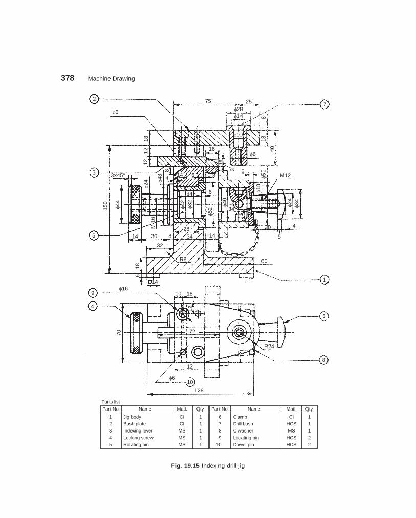
378 Machine Drawing
dharmd:\N-Design\Des19-1.pm5
Fig. 19.15 Indexing drill jig
2
�5
75 25�28�14
7
618
40
�10
�6
3 6
1612
1218
3 3×45°
150
�44
�24 �4
88
414 6 3
34 6
�42
�32
5
M16
14 30 8
32
3428
186
14
R6
14
�52
�40
34
60
1
�50
�18
M12
�24
�34
4
5
30
�169
4
10 18
12
70 72
12
�610
128
6
8
R24
Part No. Name Matl. Qty.
1
2
3
4
5
Part No. Name Matl. Qty.
Parts list
Jig body
Bush plate
Indexing lever
Locking screw
Rotating pin
CI
CI
MS
MS
MS
1
1
1
1
1
6
7
8
9
10
Clamp
Drill bush
C washer
Locating pin
Dowel pin
CI
HCS
MS
HCS
HCS
1
1
1
2
2
16

Part Drawings 379
dharmd:\N-Design\Des19-1.pm5
Fig. 19.16 Pierce and blank tool
200
�44
�20
3
�40 �24
20 14 20
�40
640
�30
�14 4
90
�14
10° 13
6
28
7
5
2
8
1
4
6
8 826
43
6
�32
8
�18
9
10 �16�44 �28
42 26
�24
22
Feed
�12
108
28
22
15
�6
15
56
R1222
22 54 120
186
220
Part No. Name Matl. Qty.
1
2
3
4
5
Parts list
Base
Die block
Cover plate
Tool holder
Punch
MS
Tool steel
MS
MS
Tool steel
1
1
1
1
1
Part No. Name Matl. Qty.
6
7
8
9
10
Blanking tool
Guide block
Guide pin
Stop
Spring retainer
Tool steel
MS
MS
HCS
MS
1
2
2
1
1

380 Machine Drawing
dharmd:\N-Design\Des19-1.pm5
Fig. 19.17 Blow-off cock
114�78�68�56
�64 3
2
�48�80
32
�94
22
�54�64
�44�60
�13280
59
22
4
1124
3
7040
5293
�40
2211
10
6
14°
8
89
8
8 9
108
4236
622
630
60 100 1
104 HOLES,
�112
�72 30
40
40
80114
R17
Part No. Name Matl. Qty.
1
2
3
Parts list
Body
Cock
Gland
CS
GM
CS
1
1
1
DIA12

Part Drawings 381
dharmd:\N-Design\Des19-1.pm5
� �����������!�1��+�
The function of a steam stop valve is to regulate the amount of steam passing through the steampipe. It is operated manually.
Figure 19.18 shows one design of a steam stop valve. The valve seat 7 is screwed into thevalve body 1. The valve 6 is attached to the spindle 8 by a collar 9 and a pin. The cover 2 isattached to the body along with the stuffing box, by studs and nuts 11. A bridge 5 is attached tothe cover, by means of two studs with collars 12. The spindle is screwed into the bridge and ahand wheel is kept in position at the end of the spindle by a nut 13. When the hand wheel isoperated, the valve moves perpendicular to the seat and allows the steam to pass from the left tothe right side of the valve.
� ������'��������0��7�1��+�
In Ramsbottom safety valve, spring load is used to lift the valves, when excess pressure of steamis built-up. It is mostly used in a locomotive boiler. Whenever steam pressure exceeds the designedvalue of the spring force, the excess pressure lifts the valves, allowing steam to escape till thepressure decreases to the permissible value.
Figure 19.19 shows the assembly drawing of a Ramsbottom safety valve. It consists of twovalve chests provided in cast iron housing 1. There are two valves 2 of the same size and shape,which are held in position against their seats 3 by the pivots of lever 5. The lever is loaded bymeans of spring 6, placed centrally between the chests. One of the pivots 4 is pinned to the lever,whereas the other is forged integral with the lever itself.
� �/��!%��������#�����
Figure 19.20 shows the assembly drawing of a diaphragm regulator. This is used on gas lines toregulate the outlet pressure of the gas. The gas enters the regulator at A and leaves from B. Theline pressure of a gas is indicated by the pressure gauge (not shown in figure) provided at C.Similarly, the outlet pressure is shown by the guage to be provided at D.
When the gas is let into the regulator, it forces the diaphragm assembly, to find its passagethrough B. For obtaining the required pressure of the gas at the outlet of the regulator, load onthe spring 4 is adjusted. The spring is located on the screw 6, by means of a locator 5 andconnected to the diaphragm assembly 2, by screwing the cover 3 onto the body 1. The requiredadjustment is thus obtained by operating the screw 6, observing the outlet pressure guage locatedat D.
� $���������#�����(���"
Plummer blocks, when they are solid, are used mainly for end supports for the shafts and cannotbe used as intermediate supports, because of the interference of the other shaft mountings, suchas gears and pulleys. The split type of plummer block, whether the plane of splitting is horizontalor inclined, is more flexible in its use and may be used as intermediate shaft support or even asend support.
The angle plummer block shown in Fig. 19.21, consists of a cast iron pedastal or base withinclined surface at 30° to the vertical. It also consists of a cast iron cover 2, which is used foradjustment of wear in the brasses 3 and for the renewal of the brasses. This also facilitates easyinstallation of the bearing. The brasses are supported in the base and they are prevented fromrotation by a snug provided in the bottom brass. The brasses are also prevented from movingaxially, by the collars provided at the ends. The cover is bolted to the base by means of two studs4 and nuts 5. For reducing the friction between the brasses and the shaft, lubricating oil isapplied through the bush 6.

382 Machine Drawing
dharmd:\N-Design\Des19-1.pm5
Fig. 19.18 Steam stop valve
�220
�50
24 M20
10
24 M246024
�28
90 �120 �36
63 �24
45
16
3036
3610
5
8
3616
0�2
40
�120
�28 50
28
39
�65
�22�160
9
2828
�22
16
9
SQTHD
123
6�32
45°
120
66
10
16
22
R22
4
R14
4
�16
f32f32 1618 9 6
625
2516
6
M140
40 16
340
4 WEBSTHICK 6
228 HOLESPCD 195
�244
36 90
R22 18
14
Part No. Name Matl. Qty.
1234567
Parts list
BodyCoverGlandNeck bushBridgeValveValve seat
CICI
GMGMMSGMGM
1111111
Part No. Name Matl. Qty.
89
1011121314
SpindleCollarHand wheelStud with nutStud with collarNutStud with nut
GMGMCIMSMSMSMS
1116212
13
10
5
28
12
3
11
2
4
1
7
�170
75
6
9
DIA 34×6
9

Part D
rawings
383
dharmd:\N
-Design\D
es19-1.pm5
Fig. 19.19 Ramsbottom safety valve
3 2 Y
96
X
R12 �24
R15 36
72
4818
�9
�60�118
X
24 3015
30
12
24
�100R10
18
6
99
9
54M81 R12
52
4
9
1
12
�72
R95
6 18
1212
30
� 12
�4840
8
�96
�240
Y
24
R12R18
R60
192
384
5
15
6
7
8
10
11
X–X
90°
66
66
12
�18 �1
2
3636
99
63
3
510 54
�60
�66
3 WINGS,
EQUI-SP
Y–Y12
15
120
�12
�18
6 612
�72
R1212
24 1845
60
M18
72
12 24
�96
�192
6 DIA9HOLES,PCD 192
Part No. Name Matl. Qty.
123456789
1011
HousingValveValve seatPivotLeverSpringSafety linkEye boltWasherNutNut
CIGMGMMSMS
HCSMSMSMSMSMS
12211121111
Parts list
R10
R15

384M
achine Draw
ing
dharmd:\N
-Design\D
es19-1.pm5
Fig. 19.20 Diaphragm regulator
R140
6
�30
3
5
122
×10
U/C
1
50
32�3
A
M20 DEEP 10
60
�68
22C
12
�12 D
R25
4
16
�44
�8
�12
M14 DEEP 11
�25
�3
B 30°
20
M64�18
�8 64
10
5
�18
M12
50
�1464
6 �6
2
4
6
22 22
�19
RECESS,
DEEP 5
R12
R3
R12
R28
Part No. Name Matl. Qty.
1
2
3
4
5
6
Parts list
Body
Diaphragm assembly
Cover
Spring (42 free length,
wire 3, 7¾ turns,
flat ends)
Locator
Screw
f
Brass
Rubber
Brass
SpS
Brass
MS
1
1
1
1
1
1
R12

Part Drawings 385
dharmd:\N-Design\Des19-1.pm5
Fig. 19.21 Angle plummer block
4
3
27
515
3
14 OIL HOLE, DIA2
CSK DIA8
R55
R43
R30
23R
32 30°
10
84
2
STUD, M10×55
5
1
77
5515
20
5
3
R4
12
20 92 78 20
SNUG, DIA6×7
44 70
15
�50
3
60 10
�14
�35
6
�63
�70
Part No. Name Matl. Qty.
1
2
3
4
5
6
Parts list
Base
Cover
Brasses
Stud
Nut with washer
Bush
CI
CI
GM
MS
MS
GM
1
1
2
2
2
1
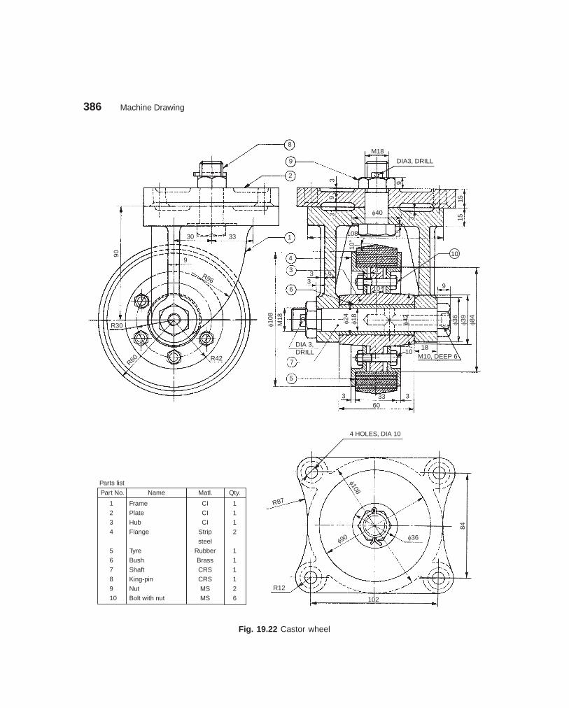
386 Machine Drawing
dharmd:\N-Design\Des19-1.pm5
Fig. 19.22 Castor wheel
8
9
�36
2
30 33
90
9
R96
R30
R60 R42
M18
DIA3, DRILL
939
3 �40
1515
3
108 1.5
1
4
3
6
3 93
3
10 9
�108
M18
DIA 3,
7
5
�24
�18
�42
�39
�84
18M10, DEEP 6
3 33360
4 HOLES, DIA 10
R87
�108
�90 �36
84
R12
102
Part No. Name Matl. Qty.
1
2
3
4
5
6
7
8
9
10
Parts list
Frame
Plate
Hub
Flange
Tyre
Bush
Shaft
King-pin
Nut
Bolt with nut
CI
CI
CI
Strip
steel
Rubber
Brass
CRS
CRS
MS
MS
1
1
1
2
1
1
1
1
2
6
10°
10DRILL
10
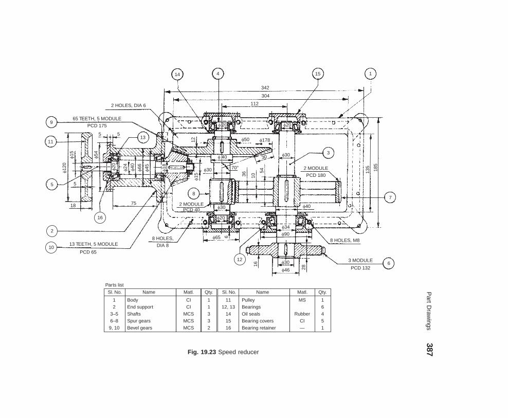
Part D
rawings
387
dharmd:\N
-Design\D
es19-1.pm5
Fig. 19.23 Speed reducer
9
11
5
2
10
14 4 15 1
13
16
8
3
7
126
2 HOLES, DIA 6
65 TEETH, 5 MODULE
PCD 175
5 5
�120
�15
5
18
�54
�20
�24
�40
�66
�45
�18
75
13 TEETH, 5 MODULE
PCD 65
8 HOLES,
DIA 8
2 MODULEPCD 40
12
�30
�15
342
304
112
�50 �178
� 40
70°
36 10
54
30 �30
2 MODULE
PCD 180
�40
135
185
�30
�20
�65 6�34
�90
16�30
�46 28
8 HOLES, M8
3 MODULE
PCD 132
�20� 20
Sl. No. Name Matl. Qty.
1
2
3–5
6–8
9, 10
Sl. No. Name
Parts list
Body
End support
Shafts
Spur gears
Bevel gears
CI
CI
MCS
MCS
MCS
1
1
3
3
2
11
12, 13
14
15
16
Pulley
Bearings
Oil seals
Bearing covers
Bearing retainer
Matl. Qty.
MS
Rubber
CI
—
1
6
4
5
1

388 Machine Drawing
dharmd:\N-Design\Des19-1.pm5
� &��������8%���
Castor wheels are used on trolleys for moving them in any direction with minimum effort. Acastor assembly is shown in Fig. 19.22. It consists of a frame 1 made of cast iron. The frame isfreely suspended from the plate 2 by king-pin 8 and nut 9. The assembly is kept intact by a split-pin. The brass bush 6 is pressed into the hub 3. The rubber tyre 5 is placed on the hub and keptin position by the two flanges 4 which are clamped by bolts 10. This wheel assembly is located inthe frame by the shaft 7. The shaft is positioned with a nut and a split-pin. A grease nipple is fixedon the head of the shaft, to provide lubrication between the shaft and bush bearing.
� )��!�������#���
Gear trains are used for transmitting power and also to change the speeds between two or moreshafts. Figure 19.23 shows a speed reducer in which bevel gears and spur gear trains are used toobtain speed reduction. It consists of the gear box body 1 to which is fixed the end support 2. Thespur gear 7 is fixed on the shaft 3 along with the roller bearings 12 and 13. The driven gear 6 isthen keyed in position.
The bevel gear 9 and spur gear 8 are mounted on the shaft 4 along with the bearings at theends. The bevel gear 10 is mounted on the shaft 5 along with the bearings. The driver pulley 11 isfixed with a key on this shaft. The speed reduction takes place in two stages between the bevelgears 10 and 9 and between spur gears 8 and 7.
The bearings are provided with bearing covers 15, oil seals 14, bearing retainer 16, andcirclips wherever necessary. Eight tapped holes of M8 and free holes of φ 8 are provided on the bodyto fix the cover. The holes of φ 6 are made in the body for dowel pin location.
��������
The assembly drawing of a speed reducer is shown in Fig. 19.23. Draw the details of the following,to suitable scale:
(i) End support 2, (ii) Shaft 4, (iii) Spur gear 7, (iv) Bevel gear 9, and (v) Bearing cover 15.

���� ���������
A production drawing, also known as working drawing, supplies information and instructions forthe manufacture or construction of machines or structures. A production drawing should provideall the dimensions, limits, special finishing processes, surface quality, etc. The particulars ofmaterial, the number of components required for the assembly, etc., are given in the title block.The production drawing of a component should also indicate the sub-assembly or main assemblywhere it will be assembled.
Since the working drawings may be sent to other companies to make or assemble the unit,the drawings should confirm with the standards followed in the country. For this reason, aproduction drawing becomes a legal document between the parties, in case of disputes inmanufacturing.
Working drawings may be classified into two groups : (i) detail or part drawings and (ii)assembly drawings.
���� ����� � ������� �������
������������� �� ��� ����
A detail or part drawing is nothing but a production or component drawing, furnishing completeinformation for the construction or manufacture of the part. This information may be classifiedas:
1. Shape description This refers to the selection of number of views to describe the shapeof the part. The part may be drawn in either pictorial or orthographic projection; the latter beingused more frequently. Sectional views, auxiliary views and enlarged detailed views may be addedto the drawing in order to provide a clear image of the part.
2. Size description Size and location of the shape features are shown by properdimensioning. The manufacturing process will influence the selection of some dimensions, suchas datum feature, tolerances, etc.
3. Specifications This includes special notes, material, heat treatment, finish, generaltolerances and number required. All this information is mostly located near the title block.
4. Additional information Information such as drawing number, scale, method ofprojection, date, names of the parts, the draughter's name, etc., come under additional informationwhich is included in the title block.
Since the craftsman will ordinarily make one component at a time, it is advisable to preparethe production drawing of each component, regardless of its size, on a separate sheet. Figures 20.1and 20.2 show the detailed drawings of a template jig and gear.
389
20������� �������
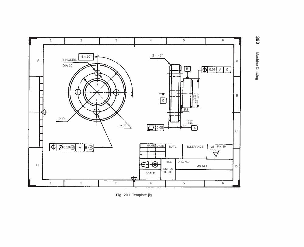
390M
achine Draw
ing
dharmd:\N
-Design\D
es20-1.pm5
Fig. 20.1 Template jig
1 2 3 4 5 6
A
D
A
B
D
1 2 3 4 5 6
4 × 90°4 HOLES,
DIA 10
� 95
� 60
0.18 M MA B
2 × 45°
B 0.05 A C
C
0.08
–0.0
0
25–0
.05
SCALE
TITLE
TEMPLATE JIG
-
DRG No.
MD 24.1
MATL TOLERANCE FINISH2512.5
NAMENAME DATE
CA
– 0.00
12– 0.25
R3

Production Drawings 391
dharmd:\N-Design\Des20-1.pm5
Fig. 20.2 Gear
1 2 3 4
2 3 4
A
B
C
D
E
F
A
B
E
F
�0.06 A2.5
1.252.5
1.25
A
�50
H7
�75
53.8
+0.
1
2 × 45°
3 CHAMFERS
0.1 A12
.512
.5
1.6 × 45°2 CHAMFERS
0.25 A30
50
Number of teeth Z 50
Module m 3
Helix angle 16°
RH
�
D rectioni
14 Js9±0.02
�50 H7+0.000+0.025
Hardness BHN 240–280
NAME DATEMATL.STEEL45 C
TOLERANCE
± 0.5
F N SHI I
2512.5
SCALE
TITLE
HELICALGEAR
DRG No.PD. 24–2
�16
1.82
–0.0
0–0
.08
+0.
0
14Js9

392 Machine Drawing
dharmd:\N-Design\Des20-1.pm5
���������� �������������� ����
It is usually made for simple machines or jobs, consisting of a relatively smaller number of simpleparts. All the dimensions and information necessary for the manufacture of a part and for theassembly of the parts are given directly on the assembly drawing. Separate views of specific parts,in enlargement, showing the mating of parts, may also be drawn, in addition to the regularassembly drawings. Figures 20.3 and 20.4 show the detailed assembly of a tea-poy and crankassembly respectively.
Fig. 20.3 Detailed assembly drawing
��������������� ��������������� ����������
The type of manufacturing process influences the selection of material and detailed features of apart (Fig. 20.5). As shown in Fig. 20.5a, if the component has to be cast, then rounds and filletsare to be added to the part. Additional material will also be provided where surface requiresfinishing.
Several drawings may be made for the same part, each one giving only the informationnecessary for a particular stage in the manufacture of the part. A component which is to beproduced by forging, for example, may have one drawing showing the forged part (Fig. 20.5b) withno machining details and a separate drawing for the machining of the forging (Fig. 20.6).

Production Drawings 393
dharmd:\N-Design\Des20-1.pm5
Fig. 20.4 Crank
����� !���"
���������� ��� �����#���������$��
Connecting rod assembly of a petrol engine, the big end of which is split into two halves is shownand described in Chapter 19 (Fig. 19.1).
The component drawings of the above assembly are shown in Fig. 20.7, with details oftolerances, surface finish, etc., as required for production work. The rod and cap are made offorged steel and machined to close tolerances at both the big end as well as the small end asshown. The bearing brasses are made of gun-metal, because it has good resistance to corrosion.
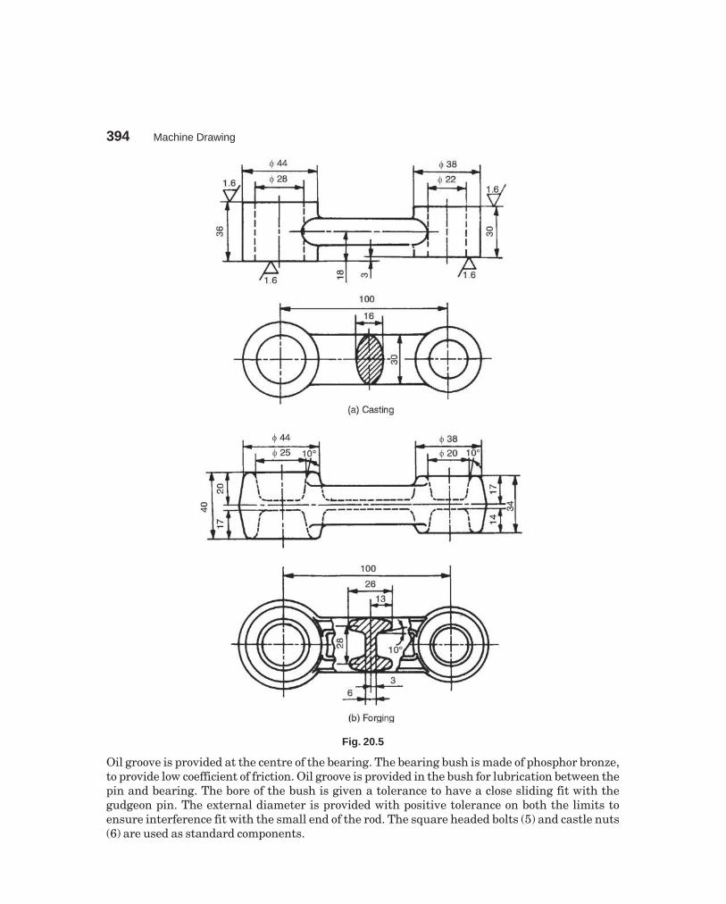
394 Machine Drawing
dharmd:\N-Design\Des20-1.pm5
Fig. 20.5
Oil groove is provided at the centre of the bearing. The bearing bush is made of phosphor bronze,to provide low coefficient of friction. Oil groove is provided in the bush for lubrication between thepin and bearing. The bore of the bush is given a tolerance to have a close sliding fit with thegudgeon pin. The external diameter is provided with positive tolerance on both the limits toensure interference fit with the small end of the rod. The square headed bolts (5) and castle nuts(6) are used as standard components.

Production Drawings 395
dharmd:\N-Design\Des20-1.pm5
Fig. 20.6
THEORY QUESTIONS
20.1 What is production or working drawing of a component?20.2 What information must be provided on production drawing of a machine to facilitate its manufac-
ture and assembly.20.3 Why working drawings must be prepared as per the standards?20.4 Classify and describe the various types of working drawings.20.5 What is a working assembly drawing?20.6 What kind of drawings are to be prepared for producing, (a) forged component, and (b) cast
component.
DRAWING EXERCISES
20.1 Prepare working drawings of the following components of the split sheave eccentric, shown inFig. 19.7.(a) Sheave piece (1)(b) Sheave piece (2), and(c) Strap (7).Indicate the fits and tolerances recommended for the above components.
20.2 Make the working drawings of the components of the angle plummer block, shown in Fig. 19.21.Indicate suitable fits and the corresponding tolerances for the parts: (a) Brasses and base, (b)Brasses and the shaft (not shown).
20.3 Study the lathe speed gear box shown in Fig. 19.10a and make a working drawing of the spindle.Indicate the tolerances, surface finish, etc., wherever necessary.
20.4 Study the milling machine tail-stock shown in Fig. 19.11 and prepare the production drawings of,(a) body (1), (b) centre (2), and (c) screw (4). Indicate the fits and the corresponding tolerances onthe body and centre. Write down the process sheet for making the body.
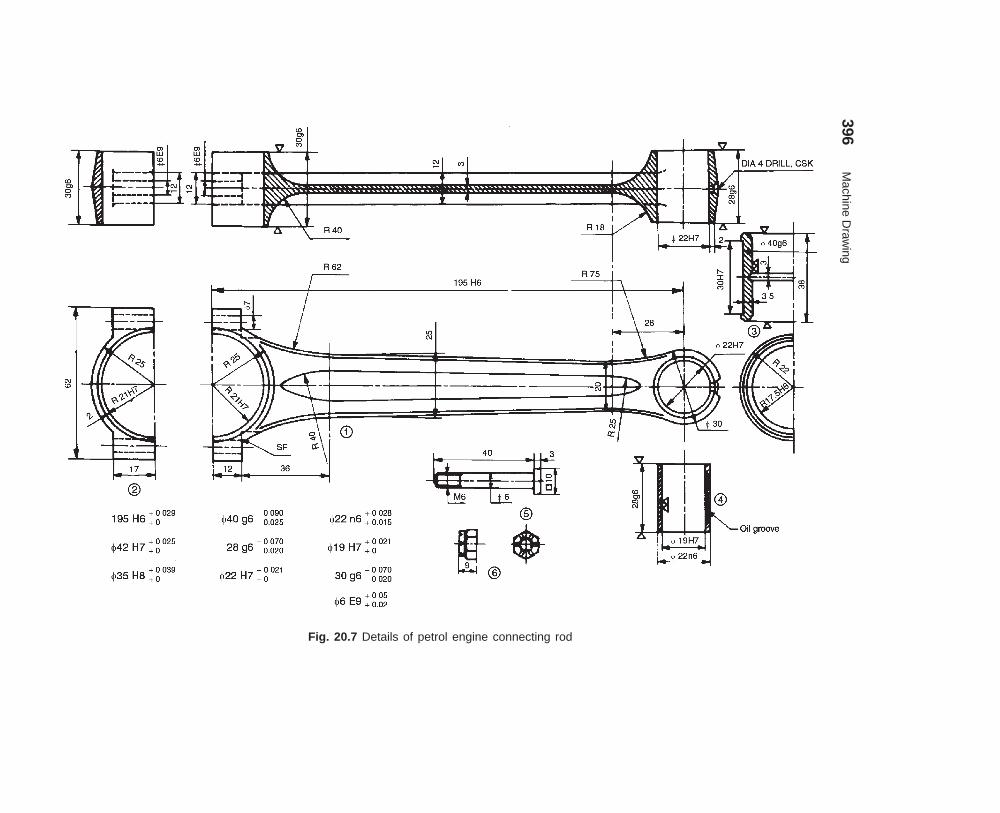
396M
achine Draw
ing
dharmd:\N
-Design\D
es20-1.pm5
Fig. 20.7 Details of petrol engine connecting rod

397
���� ����������
Engineering drawing, in general is applied to drawings for technical use and is concerned withthe direct graphical representation of designs for physical objects, as used in engineering andscience. Computer aided draughting on the other hand, is the application of conventionalcomputer techniques, with the aid of data processing systems, to present a graphical solution.It deals with the creation, storage and manipulation of models of objects and their pictures. Theuser generates graphics by interactive communication with the computer. Graphics are displayedon a video display and can be converted into hard copy with a plotter or printer.
Presently, there are many independent graphics software packages available for usewith micro-computers. Graphics package is a set of functions, which are called by the user in hisapplication program to generate the drawings and pictures. AutoCAD was developed to run onany micro-computer system.
Interactive computer graphics helps in developing simulation models of real life systems,where a lot of risk is involved otherwise. For instance, flight simulators can be used to train thepilots before handling the actual planes.
����� ������
AutoCAD provides a set of entities for use in constructing the drawing. An entity is a drawingelement such as a line, circle, etc. By typing a command on the keyboard or selecting it from amenu, the entity can be drawn. Parameters should be supplied for the chosen entity in responseto the prompts on the screen. The entity is then drawn and appears on the screen. The effect ofevery change made appears on the screen immediately.
These entities may be erased or moved or copied to form repeated patterns. Theinformation about the drawing also may be displayed.
����� ��� ���� �� �����
Computer aided graphics systems have three major components: the draughter, hardware andsoftware. The physical components of a computer constitute the hardware, such as computerterminal, input devices and output devices. Software is the draughter’s instructions to thecomputer.
������ ��������
Computers execute the instructions in the input after receiving the input from the user andthen produce output. These are classified by size, viz., main frames, mini-computers and micro-computers.
21������� ���
��������

398 Machine Drawing
dharmd:\N-Design\Des21-1.pm5
���������������
It consists of a keyboard, a cathode ray tube and inter-connections with the computer. Theterminal allows the user to communicate with the system.
���������������
Keyboard generally resembles typewriter and normally contains many functional keys. Thispermits communication through a set of alphanumeric and functional keys.
������� �!"���������#���$ ��%
A CRT is a video display device, consisting of a phosphor coated screen and electron gun. Theelectron gun throws a beam and sweeps-out raster lines on the screen. Each raster line consistsof a number of dots called pixels. By turning the pixels on and off, the images are generated onthe screen. One measure of quality of picture produced on the screen is resolution and for goodquality of graphics to be drawn, high-resolution screens are used.
�����&����!!��'
The plotter makes a drawing as instructed by the computer. Flat bed plotters and drum typeplotters are in vogue. Both black and white and colour graphics can be made by the use ofdifferent pens.
�����(�����!��'
Inexpensive impact type of printers, dot matrix printers have rectangular print heads, composedof pins which can be manipulated to form a character. These patterns of pins make dottedcharacters on paper, when they are forced against ribbon. The output of the dot matrix printersis of low quality and hence they find limited use in graphics applications. These printers areused especially when continuous paper is fed. Ink jet and laser printers are now-a-days usedwhich may be able to print on A4 size cut sheets. The print quality is very good and both linesketches and photographs can be printed. For the purpose of desktop publication, these printersare recommended.
�����)���*�!�+��'
A drawing may be scanned after placing it on the digitizer, thereby converting the picture to adigital form, based on the x, y co-ordinates of individual points. These drawings can also bestored for later use or corrected/modified. Thus, a digitizer is a graphics input device to thecomputer for display, storage or modification.
�����,�-�.�!��'�����/���.!��'
These devices enable the user to interact with the computer, in a more natural way. The locatorsgive the position information. The computer receives the co-ordinates of a point from a locator.The examples are thumb wheels, joystick, mouse, track balls, etc. The selectors are used to picka particular object, but no information is provided about its screen position, eg., light pen.
����� �/�-01� �� 2��-�31
In co-ordinate geometry, a line segment consists of infinite number of points whereas in computergraphics a segment has a finite number of pixels. A pixel is the smallest screen element, whichcan be specified individually. The entire screen resembles a two dimensional array of pixels.These points are addressed by their x and y co-ordinates; the value of x increases from left toright and y likewise from bottom to top. Displays have been built with as many as 4096 × 4096addressable points and with as few as 256 × 256. The particular points, which lie on the linesegment selected, are displayed with the required intensity. This means that they cannot bepositioned with infinite precision.

Computer Aided Draughting 399
dharmd:\N-Design\Des21-1.pm5
����������!!��*�!"�����4��*'
AutoCAD drawing may be plotted either by a pen plotter or a printer plotter. Pen plotters arevery accurate and multiple colours may be obtained. Printer plotters have limited resolutionand smaller paper sizes and produce monochrome output. However, printer plotters are usuallyfaster than pen plotters. For pen plotter, PLOT command is used, whereas for a printer plotter,PRPLOT command is used.
While beginning a plot from the main menu, tell AutoCAD, which portion of the drawingto be plotted. Specify the part of the drawing to be plotted by entering: Display, Extents, Limits,View or window: the response specifies a rectangular area of the drawing.
By Specifying:D (Display) — this option plots the view that was displayed in the current view
port just prior to the last SAVE or END command for that drawing.E (Extents) — this option is similar to ZOOM extents. The extents are updated
automatically as one draws new entities.L (Limits) — plots the entire drawing area as defined by the drawing limits.V (View) — plots a view that was previously saved, using the drawing editor’s
view command.W (Window) — plots any portion of the drawing. Specify the lower left corner and
upper right corner of the area to be plotted.
���&� 50/ /��6�����0��3� /1/���Operating system falls in the category of system software. An operating system is a set ofprograms designed to manage the entire operations of computer system. Basically the operatingsystem performs two fundamental tasks for the computer:
(i) managerial task (ii) interface taskThe operating system does not do any specific task, but it is a general program which
assists the user by doing the following operations:— Controlling all the operations including input/output operations, arithmetic operations
and internal transfer of information.— Communicating with peripheral devices (printer, disk and tape device).— Supporting the running of other software.One can say that the computer system without an operating system is like an office
without a manager.
���(� /�0���3� 0#!� 0�
Once AutoCAD 2004/05 software is located on to the computer and the operating system isavailable, one can start using the facility. Soon the computer is turned on, the operating systemis automatically loaded. Various application icons appear on the windows screen. AutoCAD canbe started by double-clicking on the AutoCAD icon available on the desktop of the computer.
The various components of the initial AutoCAD screen are as shown in Fig. 21.1 andFig. 21.2 consisting of :
1. Drawing Area The drawing area covers a major portion of the screen. Various objectscan be drawn in this region by the use of AutoCAD commands. The position of thepointing device is represented on the screen by the cursor. On the lower left corner, acoordinate system icon is present. On the top right corner, standard windows buttonsare also available.
2. Command Window At the bottom of the drawings area, command window is presentand commands can be entered by keyboard.

400 Machine Drawing
dharmd:\N-Design\Des21-1.pm5
3. Status Bar At the bottom of the screen, status bar is displayed, which will make it easyto change the status of some AutoCAD functions by proper selection.
4. Standard Tool Bar Standard tool bar displays coordinates and they will change onlywhen a point is specified. The absolute coordinates of the cursor will be specified withrespect to the origin.
5. Snap Snap mode allows the cursor to be moved in specified/fixed increments.6. Grid By choosing this button, grid lines are displayed on the screen and can be used as
reference lines to draw AutoCAD objects.7. Ortho By selecting the orthomode, lines can be drawn only at right angles on the screen.8. Polar The movement of the cursor is restricted along a path based on the angle set as
the polar angle. One can use either polar mode or orthomode only at a particular time.One can also use function keys for quick access to certain commands. Only important functionsdefined by AutoCAD 2004 are given below:
Function Key Function
F1 Online helpF2 Toggles between command window on and offF5 Switches among Isoplanes Top, right and leftF6 Toggles between coordinates on and offF7 Toggles between grid on and offF8 Toggles between orthomode on and offF9 Toggles between snap mode on and offF10 Toggles between Polar tracking on and off
������ ������� ������ ����!�"#
After starting AutoCAD and when the cursor is in the drawing area, to perform an operation,commands must be invoked. The following methods are provided to invoke the commands.
1. Keyboard Using keyboard, command name can be typed at the command prompt andby pressing ENTER or SPACE BAR, the command can be invoked.
2. Menu The menu bar is at the top of the screen which displays the menu bar titles. Asthe cursor is moved over this, various titles are highlighted and by means of pick button,a desired item can be chosen. Once it is selected, the corresponding menu is displayeddirectly under the title. A command can be invoked by picking from this (Fig. 21.3a).
3. Draw Toolbar This is an easy and convenient way to invoke a command. This isdisplayed on the left extreme of the initial AutoCAD screen (Fig. 21.3b) and very easy tochoose by picking.
4. Tool Palettes These are shown on the right side of the monitor screen (Fig. 21.2). Aneasy and convenient way of placing blocks/patterns of hatching in the present drawing.By default, AutoCAD displays the tool palettes on the right of the drawing area. Varioushatching patterns also can be selected from this.
������ �����!$���� ��$%��&��#
Developing a drawing by AutoCAD is done by interactive technique, so that it is easy to follow andachieve the results. The popular interactive techniques are layers, drawing insertion, objectsnap, zooming, panning, plan view and 3D views, view ports, resolution, editing the drawingand many more.

Computer Aided Draughting 401
dharmd:\N-Design\Des21-1.pm5
Fig. 21.1
Fig. 21.2

402 Machine Drawing
dharmd:\N-Design\Des21-1.pm5
Fig. 21.3 (a) Invoking the ELLIPSE 21.3 (b) The Draw toolbar
The layering concept is similar to the transparent overlays used in many draughtingapplications. This allows the user to view and plot-related aspects of a drawing separately or inany combination. In drawing insertion, a drawing can be stored in a drawing file and this maybe inserted in subsequent drawings for any number of copies. To refer to geometric features ofexisting objects when entering points, the object snap may be used. The visual image of thedrawing on the screen may be magnified or shrunk by zooming. Whereas, panning allows viewingdifferent portions of the drawing, without changing the magnification. In plan view, theconstruction plane of the current user co-ordinate system is parallel to the screen. The drawingmay also be viewed from any point in space (even from inside an object). The graphics area ofthe screen can be divided into several view ports, each displaying a different view of the drawing.Physical resolution refers to the amount of detail that can be represented. This resolution canbe changed at any time. The editing facilities of AutoCAD make it easy to correct or revise adrawing. Multiple copies of an object, arranged in rectangular or circular patterns are easy tocreate.
���)� �-0���3� 6���0���0�3
While planning a drawing in Auto CAD, one has to organize some of the information such aschoosing the units, co-ordinates, etc.���)��� �7������!��/�'!��
The system used by all the CAD packages is generally the rectangular cartesian co-ordinatesystem designated as x, y and z axes. The positive direction of these axes follows the right handrule. Any point in space can therefore be designated by the co-ordinate values of these 3 axes.viz., x, y and z.

Computer Aided Draughting 403
dharmd:\N-Design\Des21-1.pm5
The co-ordinates can be input into the system by:(i) The direct input of co-ordinate values in the respective order of x, y and z. If z co-
ordinate is not mentioned, then the values are assumed to be at a single given level.(ii) Specifying the co-ordinates in an incremental format from the current cursor posi-
tion in the drawing area. The distance is specified by using @ parameter before theactual values. The incremental values apply to all the ordinates.
(iii) Point co-ordinates may also be specified using the polar co-ordinate format. It canalso be an extension of the incremental format.
(iv) Using the mouse button, the cursor may be taken to the required position and thebutton is clicked.
It is generally necessary to specify the limits of the drawing with the help of the commandLIMITS, where the user will be asked to specify the lower left corner and upper right corner ofthe drawing sheet size. This establishes the size of the drawing.
���)���5�'�.�3����!��.� ������'
By way of choosing the basic commands in AutoCAD, one can make simple drawings. Thevarious entities that can be used for making an AutoCAD drawing in 2D are: point, line, ellipse,polygon, rectangle, arc, circle, etc.
Generally AutoCAD provides a default option as <> in each of the command response.The value shown in the angle brackets is the most recently set value. To have the same value,one has to simply press the <Enter> key. The various options available for each command areshown in the command window. But the user need to respond by choosing one letter in mostcases, which makes the AutoCAD choose the right option.
���)������4��*���!�!�7����
The point command locates a point in the drawing.Command: POINT (one has to give the location)POINT: 25, 45 location of the point. Thus, a point is placed at the given location (25, 45).After setting the limits of the drawing, the following drawing aids/tools may be used to
locate specific points on the screen (electronic drawing sheet).ORTHO Command—this is orthogonal drawing mode. This command constrains the lines
drawn in horizontal and vertical direction only.Command: ORTHOON/OFF <current>:
SNAP Command—this command is used to set increments for cursor movement. If thescreen is on SNAP mode, the cursor jumps from point to point only. The cursor movement canbe effectively controlled using the SNAP command. This is useful for inputting the data throughdigitizer/mouse.
Command: SNAPSnap spacing or ON/OFF/Aspect/Locate/Style <current>: 0.1 (default)
GRID Command-working on a plain drawing area is difficult since there is no means forthe user to understand or correlate the relative positions or straightness of the various objectsmade in the drawing. The command enables to draw dotted lines on the screen at pre-definedspacing. These lines will act as graph for reference lines in the drawing. The grid spacing can bechanged at will. The grid dots do not become part of the drawing.
Command: GRIDGrid spacing or ON/OFF/Snap/Aspect <0>: 0.5 (default)

404 Machine Drawing
dharmd:\N-Design\Des21-1.pm5
Function keys may create drawing aids/tools also. The function keys F7, F8 and F9 act astoggle keys for turning ON or OFF of GRID, ORTHO and SNAP tools respectively.
HELP Command—AutoCAD provides with complete help at any point of working in theprogram. HELP can be obtained for any of the individual commands. Most of the informationrequired by the user is generally provided by the help which is always instantaneous.
SAVE Command—AutoCAD provides the following commands to save the work/drawingon the hard disk/ floppy diskette:
SAVE SAVEAS QSAVECommand: SAVESave drawing as <current name>: KLNI
���)������4��*���!�!�7-��
Lines can be constrained to horizontal/vertical by the ORTHOcommands. CLOSE option uses the starting point of the firstline segment in the current LINE command as the next point.
1. Lines can be drawn using co-ordinate system(rectangular cartesian co-ordinates). To draw arectangle (Fig. 21.4a):
Command: LINEFrom point: 10, 20 ↵To point: 40, 20 ↵To point: 40, 60 ↵To point: 10, 60 ↵To point: ↵
2. It is also possible to specify the co-ordinates inthe incremental format as the distances from thecurrent cursor position in the drawing area. Thedistance is specified by using the @ parameterbefore the actual value. To construct a triangleof given altitude (30) and base (40) (Fig. 21.4b):
Command: LINEFrom Point: 10, 20 ↵To point: @ 40, 0 ↵To point: @ – 20, 30 ↵To point: ↵
3. It is also possible to specify the point co-ordinateusing the ploar co-ordinate format. To construct ahexagon (Fig. 21.4c) of side 30:
Command: LINEFrom point: 10, 20 ↵ (A)To point: @ 30<0 ↵ (B)To point: @ 30<60 ↵ (C)To point: @ 30<120 ↵ (D)To point: @ 30<180 ↵ (E)To point: @ 30<240 ↵ (F)To point: close
(40, 60)(10, 60)
(10, 20) (40, 20)
(a)
(30, 50)
(10, 20) (50, 20)
(b)
Fig. 21.4
CF
E D
A B(10, 20)
(c)
240° 180°
120°
60°

Computer Aided Draughting 405
dharmd:\N-Design\Des21-1.pm5
���)�&����4��*���!�!�7�--�/�
This command allows one to draw ellipses or egg shaped objects. From Release 13 onwards,ellipse is treated as a separate entity. The methods available for making ellipses are:
1. By means of axis end points: (Fig. 21.5a)Command: ELLIPSE <axis end point 1>/ center: point ↵Axis end point 2: (point)
Axis end point
Axis endpoint 1
Axis endpoint 2
(a)
Axis end point
Axis endpoint
(b)
Centre
Fig. 21.5
<other axis distance>/ Rotation:Now, if the distance is entered, AutoCAD interprets it as half the length of the other axis.2. By means of centre, axis end points (Fig. 21.5b)
Command: ELLIPSE <axis end point 1>/ centre: C ↵Centre point and one end point of each axis should be provided for the response of the
AutoCAD.
���)�(����4��*���!�!�7��-13��
This option permits to make/draw polygons from 3 to 24 sides in a number of ways:1. For making inscribed/circumscribed polygon with a side parallel to x-axis: (Fig. 21.6a, b)
(100, 200)
(a) Inscribed
(100, 200)
(b) Circumscribed
Fig. 21.6
Command: POLYGONNumber of sides: 8Edge/ <centre of polygon>: 100, 200 ↵Inscribed / circumscribed about a circle (I/C): I or C ↵Radius of circle: 80

406 Machine Drawing
dharmd:\N-Design\Des21-1.pm5
2. With edge option, specifying the size of the edge andorientation: (Fig. 21.7)
Command: POLYGONNumber of sides: 7Edge/<center of polygon>: E ↵First end point of edge: 15, 15 ↵Second end point of edge: 15, 30 ↵
The above and various other entities that can be usedfor making an AutoCAD drawing may also be selectedfrom the tool bar.
���)�)����4��*���!�!�7�� �0�3-�
A rectangle is a polygon based on two opposite cornerpoints, known as diagonal points (Fig. 21. 8).
Command: RECTANGLEFirst corner: 10, 15 ↵Second corner: 60, 50 ↵
Or from the tool bar menu icon, the pointing device can drag the rectangle and therectangle can be completed.
���)�,����4��*���!�!�7 � -�
Circle command offers several methods for drawing circles, the default being to choose a centrepoint and enter or pick a diameter or radius (Fig. 21. 9).
R2B
Centre, radius Centre, diameter
f40
3-points
2-points
2
1
R
TTR-Option
Fig. 21.9
Command: CIRCLE1. 3P/ 2P/ TTR/ <centre point>:
Pick a centre point or enter an option
(15, 30)
(15, 15)
Fig. 21.7
(60, 50)
(10, 15)
Fig. 21.8
Computer Aided Draughting 407
dharmd:\N-Design\Des21-1.pm5
2. Diameter/ <Radius><current default>: select D or R
3. 3P (3 point) option: one is prompted for a first, second and third point. The circle willbe drawn to pass through these points.
4. 2p (2 point) option: one is prompted for the selection of two points which form theopposite ends of the diameter.
5. TTR option: allows one to define a circle based on two tangent points and a radius.The tangent points can be on lines, arcs or circles.
���)�8����4��*���!�!�90�
Arc command permits to draw an arc, using a variety of methods.
Command: ARC
1. Centre/ <start point>: pick a start point using mouse or select C for more options.
2. Centre/End/ <second point>: pick a second point of the arc or select C, if option is C.
3. Angle/length of chord/end point: pick end point of the arc, if option is E.
4. Angle/Direction/Radius/ <centre point>: pick end point of the arc or specify the option.Options (Fig. 21. 10.)
Angle — “included angle” prompt appears, to enter the value.
Centre — enter the location of an arc’s centre point-at the prompt centre-pick apoint,
Direction — enter a tangent direction from the starting point of an arc. At this prompt,pick a point with cursor.
End — at this prompt, pick the end point of the arc.
Length — enter the length of a arc’s chord. At this prompt, enter a length or dragand pick a length with cursor.
Radius — at the prompt “radius”, enter a radius value.
Start point — enter the beginning point of an arc.
���,� �5:� �� /�-� ���
Editing capabilities are the most useful part of AutoCAD system, by making use of the alreadyexisting drawing. For the purpose of editing an object, it is necessary to make selection of theobjects in the drawing. There are various options available for the selection of an object:
1. Pick box—the cursor is converted to a small box/square, called pick box. By pressingthe left button of the mouse when the pick box touches an entity, the object can beselected for editing.
2. Window option—a single or group entities can be selected by bringing them fully insidea rectangular window. Entities, which lie only partially inside the boundaries of window,will not be selected. Rectangular window may be created by picking the first corner, bypressing the left button and then moving the mouse to the desired position of diagonallyopposite corner. Selection of the object is complete, by pressing the button again.

408 Machine Drawing
dharmd:\N-Design\Des21-1.pm5
1
2
3
3-point
2
3Centre, start, end
1
1
Start, centre, angle
3
2
1
Start, centrelength (of chord)
2
3
12
angle
Start, end, angle
1
2
Start, end, angle
Radius1
Start, end, direction
2
3
1
3Start, centre, end
2
Centre, start, angle
1
2 angle
Centre, start, length
1
2
Length ofchord
Fig. 21.10
���,������!� ������'
The commands used for modifying the drawings fall under this category. Using these commands,the objects may be erased, retrieved, moved to another location, made into multiple copies,rotated, enlarged, mirror imaged, part of a drawing may be moved and the above effects canalso be reversed (undo).
ERASE Command—this lets the entities to be permanently removed from the drawing.The command format is
Command: ERASE
Select objects: (desired objects) once it is entered, the objects/portion of the object is erased/deleted.
OOPS Command—this restores the entities that have been inadvertently ERASED.Whenever ERASE command is used, a list of entities erased is retrieved by this command.
Command : OOPS
Once it is entered, it restores all the entities erased by the recent ERASE command.Once another ERASE is done, the list of entities erased by the previous ERASE command isdiscarded. OOPS cannot be used to restore them.
AutoCAD allows backup step by step to an earlier point in an editing session, usingthe UNDO command. This stores all the sequences made by the user in the current drawingsession.

Computer Aided Draughting 409
dharmd:\N-Design\Des21-1.pm5
UNDO Command—this command allows to undo several commands at once. Thiscommand is used for correcting any errors made in the editing process. When a SAVE option isused, then the UNDO cannot do anything before that.Command: UNDO
If the response contains a number, that many number of preceding operations will beundone.
REDO Command—if REDO is entered immediately after a command that undoessomething, it will undo the UNDO.Command: REDO
An UNDO after REDO will redo the original UNDO.OFFSET Command—this constructs an entity parallel to another entity at either a
specified distance or through a specified point.MIRROR Command—this allows to mirror the selected entities in the drawing. The
original objects can be deleted (like a move)/retained (like a copy).MOVE Command—the move command is used to move one/more existing drawing entities
from one location in the drawing to another.COPY Command—this is used to duplicate one or more existing drawing elements at
another location without erasing the original.
���,����;���� ������
This command acts like a Zoom lens on a camera. It is used to change the scale of the display.This can be used to magnify part of the drawing to any higher scale, for looking closely at somefine detail in the drawing. This is often quite useful during the construction stage. If zoomcloser, more details are visible but only a part of the drawing is seen, whereas if zoom out,larger portion of the drawing is seen but less details are visible. This command can be invokedfrom standard tool bar, from the pull down menu bar, from screen menu or from the commandarea by entering zoom.Command: ZOOM
All /Centre/ Dynamic/Left /Previous /Vmax/Window/ <scale>:By choosing the option:All — complete drawing is seen in the drawing limits, even though a part of the
drawing lies outside the limits, earlier.Centre — this option permits to specify the desired centre point. By specifying the
height of window, the magnification can be increased/decreased.Left — it permits to specify the lower left corner of the display window instead of
the centre.Dynamic — this displays the portion of the drawing specified already. Generally selects
any portion of the drawing.Extents — all the objects in the drawing are magnified to the largest extent possible
in display.Previous — the previous display extents are restored to the monitor, but the erased
objects do not reappear.Window — by entering two opposite corners of a window, the area inside the window
is enlarged /reduced.

410 Machine Drawing
dharmd:\N-Design\Des21-1.pm5
Scale — by entering a display scale factor, the size of the object can be changed atwill in its appearance.
���,��� ��''7"�!."��*�������!!����6�����*
It is common practice to fill an area with a pattern of some sort. The pattern can help differentiatebetween components, or it can signify the material composition of an object. This is accomplishedby HATCH command. Hatching generates line entities for the chosen pattern and adds them tothe drawing. AutoCAD normally groups these lines into a general block.
HATCH Command—performs hatching. The pattern filling is illustrated in Fig. 21.11,by selecting appropriate choice in response to HATCH command.
Command: HATCHPattern (? Name/ u, style) <default>:
Pattern name may be entered by choosing various available patterns which will bedisplayed by choosing u, by interaction, the angle, spacing between the lines and double hatcharea may be specified. By choosing style (Fig. 21.11), pattern filling may be achieved.
ab
Area to be hatched
abab
Normal style(default)
ab
Outer most style
abab
Ignore style
Fig. 21.11
���,��� !���!�� ������'
END Command — this command exits the drawing editor and returns to the mainmenu and updates the drawing file.
SAVE Command — this command saves the new/modified drawing and returns to themain menu. However, without exiting the drawing editor, if thechanges are to be periodically saved, it is desirable to use thiscommand. It protects the work from possible power failures, editingerrors, etc.
Command: SAVEFile name <current>: return to save the current fileQUIT Command — this exits the drawing editor without saving the updated version
of the current drawing and returns to the main menu. The AutoCADchecksup with the user for one more confirmation to avoid theaccidental quitting since all the editing work done would be lost.
TEXT Command — text may be added to a drawing by means of the TEXT command.Text entities can be drawn with a variety of character patterns orfonts and can be stretched, compressed or drawn in a verticalcolumn by applying a style to the font.
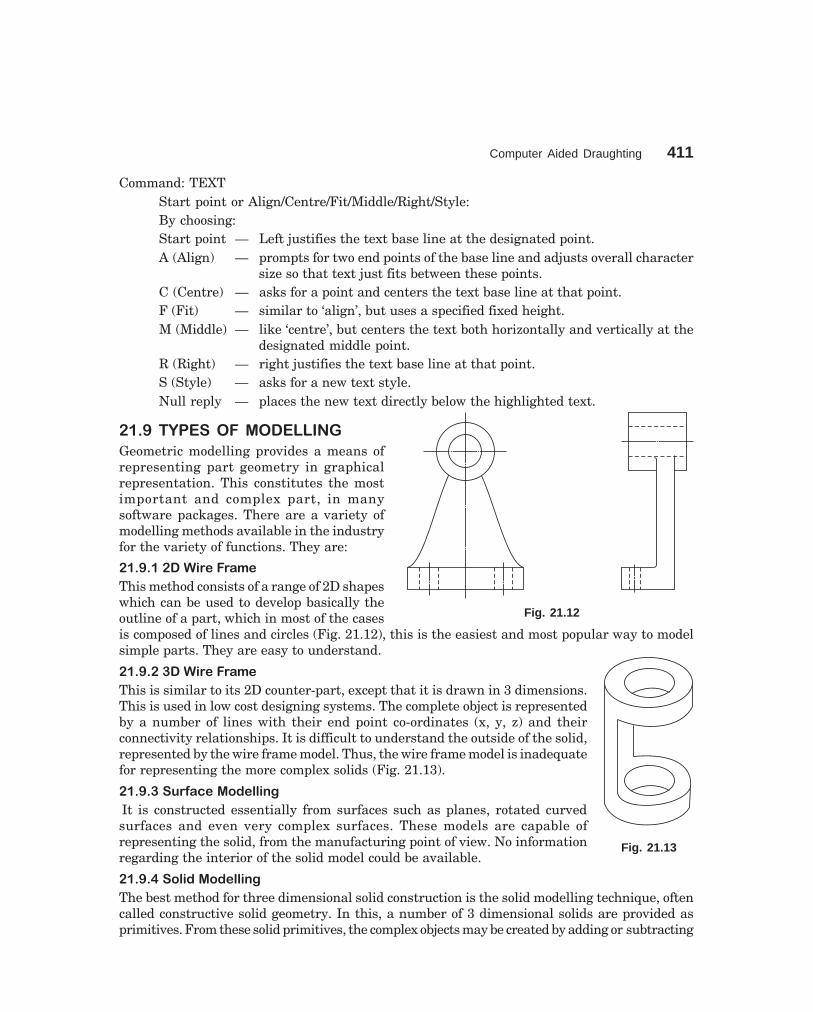
Computer Aided Draughting 411
dharmd:\N-Design\Des21-1.pm5
Command: TEXTStart point or Align/Centre/Fit/Middle/Right/Style:By choosing:Start point — Left justifies the text base line at the designated point.A (Align) — prompts for two end points of the base line and adjusts overall character
size so that text just fits between these points.C (Centre) — asks for a point and centers the text base line at that point.F (Fit) — similar to ‘align’, but uses a specified fixed height.M (Middle) — like ‘centre’, but centers the text both horizontally and vertically at the
designated middle point.R (Right) — right justifies the text base line at that point.S (Style) — asks for a new text style.Null reply — places the new text directly below the highlighted text.
���8� �1��/��6�����--�3
Geometric modelling provides a means ofrepresenting part geometry in graphicalrepresentation. This constitutes the mostimportant and complex part, in manysoftware packages. There are a variety ofmodelling methods available in the industryfor the variety of functions. They are:
���8����������6����
This method consists of a range of 2D shapeswhich can be used to develop basically theoutline of a part, which in most of the casesis composed of lines and circles (Fig. 21.12), this is the easiest and most popular way to modelsimple parts. They are easy to understand.
���8����������6����
This is similar to its 2D counter-part, except that it is drawn in 3 dimensions.This is used in low cost designing systems. The complete object is representedby a number of lines with their end point co-ordinates (x, y, z) and theirconnectivity relationships. It is difficult to understand the outside of the solid,represented by the wire frame model. Thus, the wire frame model is inadequatefor representing the more complex solids (Fig. 21.13).
���8���/#�<�.����������*
It is constructed essentially from surfaces such as planes, rotated curvedsurfaces and even very complex surfaces. These models are capable ofrepresenting the solid, from the manufacturing point of view. No informationregarding the interior of the solid model could be available.
���8���/�������������*
The best method for three dimensional solid construction is the solid modelling technique, oftencalled constructive solid geometry. In this, a number of 3 dimensional solids are provided asprimitives. From these solid primitives, the complex objects may be created by adding or subtracting
Fig. 21.12
Fig. 21.13

412 Machine Drawing
dharmd:\N-Design\Des21-1.pm5
the primitives. A solid is a model that clearly identifies any point in space at either inside oroutside of the model. Each body is represented as a single object and not as a complex collectionof surfaces.
����=� �������
One can view a drawing from any point in space. The VPOINT command permits to set theviewing point for the current view port. AutoCAD generates the drawing, projecting the entitiesso that they appear as one would see them from that point in space.
Command: VPOINTRotate/<view point><current>.
By choosingRotate: specify the view point in terms of two angles; one with respect to the x-axis (in x-y
plane) and another from x-z plane.<view point>: one can enter x, y and z components of the desired view point (separated by
commas). A specification of “1, -1, 1” would produce top, right, front view. To generate perspectiveviews, one has to use DVIEW command.
EXAMPLE: An upright cylinder at zero elevation with a radius 10 units and a height of40 units and enclosed in a square box (at zero elevation with a thickness of 15 units) can beproduced with the following sequence of commands:
Command: ELEVNew current elevation <0>: ↵New current thickness <0>: ↵Command: CIRCLE (draw a circle with 10 units of radius)Command: ELEVNew current elevation <0>: ↵New current thickness <40>: 15 ↵Command: LINE (draw a square around circle)In the normal 2D (top) view, this would appear on the screen as shown in Fig. 21.14a. With
a view point (1, -1, 1) top, right side, front views appear as shown in Fig. 21.14b.
(a)
(b)
Fig. 21.14

Computer Aided Draughting 413
dharmd:\N-Design\Des21-1.pm5
����'�� ()����� ��)��"��!��# (��*+#, �#�-!.�"
0, 0, 1 top view0, – 1, 0 front view1, 0, 0 R side view– 1, 0, 0 L side view1, – 1,1 top, front, right side view– 1, – 1, 1 top, front, left side view
������ ��� ����/
The rectangular portion of the graphics screen in which a drawing is displayed is called theview port. The screen may be divided into multiple view ports and individual controls can beexercised on each view port. One can have upto 4 view ports on screen at once (Fig. 21.15).AutoCAD Release 13 can display 16 view ports maximum on the computer monitor. Each viewport can display a different view of the drawing. Panning and zooming can be performed in eachview port independently. View ports are useful for checking the correctness of a design. Onecan edit the drawing in one view port and immediately see the results in all the view ports.
Though several view ports can be displayed on the screen, one can work in only one of theview ports at a given time, known as current view port. This active view port is recognized by aheavy border. The cursor will be in the form of cross hairs when it is inside the current port andwill be an arrow outside it. Various views may be displayed in these view ports, such as: 3Dview, top view, side view, front view, etc.
Command: VIEW PORTSSave/restore/delete/join/single/?/2/ <3>/4:
Fig. 21.15
By choosing:Save option — the active view port can be saved by giving a name upto 31 characters
and may be recalled at any time.Restore option — this restores any saved view port configuration. However, name of
the configuration to restore, has to be supplied.

414 Machine Drawing
dharmd:\N-Design\Des21-1.pm5
Delete option — it deletes a saved view port configuration by supplying the particularname of the view port to be deleted.
Join option — it allows two adjacent view ports into a single view port by selectingfirst the dominant view port and then selecting the other view port.The dominant view port will inherit the second view port by mergingboth.
Single option — this allows to display a single view port, displaying the activeconfiguration.
? option — it displays the number and co-ordinates of the current view portand the identification number and screen positions along with thenames and screen positions of the saved view port configurations.
2 option — it allows the division of the current view port into equal parts, eitherhorizontally or vertically, based on the choice.
3 option — it permits the division of the current view port into three ports.4 option — it creates 4 windows of equal size.
������ ��0�����6� ��� ������/
From the basic 3D primitives more complex solids can be built. A few such simple solids areshown in Fig. 21.16.
(a) (b) (c)
Fig. 21.16
��������������4��� �������
Cylinder offers several methods of drawing a 3D solid cylinder. The default is to choose a centrepoint, then pick or enter the diameter/radius and height.
Command: CYLINDER
1. Elliptical / <centre point> <0, 0, 0>: ↵ or pick a centre point2. Diameter / <radius>: provide a diameter or radius by picking or entering3. Centre of other end / <height>: pick a point or enter a value
Options:
Centre — allows to create a cylinder with a circular base.Elliptical — allows to create a cylinder with an elliptical base.Centre of other end — allows to specify top end of the cylinder.Height — allows to specify the height of the cylinder.
Computer Aided Draughting 415
dharmd:\N-Design\Des21-1.pm5
��������������4� ���
Cone offers several methods for drawing a 3D solid cone. The default is to choose a centre point,then pick or enter the diameter/radius and apex.
Command: CONE1. Elliptical /<centre point> <0, 0, 0): pick a centre point or enter E2. Diameter / <radius>: provide a diameter or radius3. Apex /<height>: provide the apex or height
Options:Centre — allows to create a cone with a circular base.Elliptical — allows to create a cone with an elliptical base.Centre of other end — allows to specify top end of the cone.Height — allows to specify the height of the cone.
��������������4���5�>
The box command creates a 3D solid box.
Command: BOX1. Centre/ <corner of box> <0, 0, 0>: pick up the first corner point for the box2. Cube/length/ <other corner>: pick up a second corner point or enter a value3. <Height>: provide the box height by picking two points or entering a valueOptions:Centre — allows to create a 3D box using a specified centre point.Cube — allows to create a 3D box with all sides equal.Length — allows to enter values for length, width and height.
������ ��0�����6� ����/��� /�-�/
Complex solids can be created from both solid primitives and swept solids. Boolean operationscan be used to create composite solids from two or more solids. Solid modelling is a built-infacility with AutoCAD 14, which provides for region and solid modelling. Region models are twodimensional closed areas consisting of lines, polylines, arcs, circles and ellipses. From these,mass properties and surface areas can be assessed. Solid models are true shape 3D objects.
The region command allows creating 2D enclosed areas from existing overlapping closedshapes (loops).
����������� ���!����*���'
Command: REGION1. Select objects: select objects to be combined into a region2. Press: ↵A composite region may be created by subtracting, combining or finding the intersection
of regions.To create composite regions (Fig. 21.17a, b):
Command: Union, Subtract and Intersect1. Select objects: select the regions to be combined into a composite region2. Press ↵ to end the command

416 Machine Drawing
dharmd:\N-Design\Des21-1.pm5
Objects may be selected in any order to unite them with the union command and when itis required to subtract one region from the other, first select the region from which it is requiredto subtract. Condition: these regions exist overlapping, earlier to the operations.
(a) Union (b) Subtract
Fig. 21.17
��������/�������������*
A composite solid can be created from both solid primitives and swept solids or by extruding a2D object, Boolean operations can be used.
Options:
Union — allows combining the volume of two or more solids into one. Select theobjects to join and AutoCAD creates a single composite object.
Subtract — allows to remove the common area shared by two sets of solids. One mustfirst select the solid from which to subtract and then the solid (s) whichare to be subtracted.
Intersect — allows creating a composite solid that contains only the common volumeof two or more overlapping solids.
����������''����?��!�
Mass prop calculates and displays the mass properties of 2D and 3D objects. For solids, it providesvolumetric information such as mass, volume, centre of gravity, principal axes and moments ofinertia.
Command: MASS PROP
1. Select objects: pick the solid model (s) to be analysed. This will display all the propertiesof the object(s) on the screen
2. Write to a file <N>: if one wants the information written to a file, type Y and providea file name.
For regions, the mass properties displayed are area, perimeter, centroid, moment of inertia,product of inertia and radius of gyration.
������ /� ���0-� ��
When a section plane cuts a part of the solid and the remaining part of the solid is projected,that view is known as sectional view. Sectional views are chosen to reveal the inner details (hidden).One may use full section, half section or off-set section to reveal the hidden details of the object

Computer Aided Draughting 417
dharmd:\N-Design\Des21-1.pm5
150°
30°
Top
Left Right
90°
(refer Chapter 2 and section 2.6) and the sectioned zone in any view is shown by cross-hatchedlines. Thin lines represent the cross-hatched lines. It is possible to change the hatching lines.
SOL VIEW uses orthographic projections with floating paper space view ports to layoutmulti-and sectional view drawings of 3D solids.
Command: SOLVIEW
UCS/ ORTHO/ AUXILIARY / SECTION/ <EXIT>:By choosing the option section-use the original view port and specify two points at the
prompts to define the section plane. Then define the viewing side by specifying a point on oneside of the cutting plane, for the next prompt.
����&� /����� � ��0�3
The command “isoplane” permits to switch the cursor orientation between the left, top andright isometric planes when the snap mode is set to the isometric style.
Command: ISOPLANE
Left /top/ right/ <toggle>: enter the choice to move to right, isoplane left or isoplane top.By pressing ctrl and E keys simultaneously, toggle takes place between the isometric planes.
����&���/�!!��*�'���!��.�3��������/��?
Use snap command for choosing between thestandard orthogonal snap style and isometric snapstyle-by selecting style. The grid points are arrangedalong 30°, 90° and 150° lines. The distance betweenthe grid lines is determined by the vertical spacing.
To draw the cube in isometric view(Fig. 21.18):
Command: isoplane-by choosing top, left andright planes, one at a time, the squares are drawn tocomplete the cube. Isometric circles are drawn usingthe command ellipse and selecting iso-circles option.This is possible when isometric snap is on.
����(� 50/ � ����/���3
In many applications, a drawing should contain annotations showing lengths or distances orangles between objects to convey the desired information. Dimensioning is the process of addingthese annotations to a drawing. AutoCAD provides four basic types of dimensioning; linear,angular, diameter and radius.
DIM and DIMI Commands—DIMI command allows executing one dimensioning commandand then returns to the normal command mode. If several dimensioning commands are to beexecuted, DIM command should be used. In this mode, the normal set of AutoCAD commandsis replaced by a special set of dimensioning commands. To end the process of dimensioning,EXIT command has to be used.
The dimensioning commands can be grouped into six categories:1. Linear — is done with a horizontal, vertical, aligned and rotated command.
However, rotated command requires specifying the dimension lineangle explicitly.
Fig. 21.18

418 Machine Drawing
dharmd:\N-Design\Des21-1.pm5
80
Horizontal
60 20
Continuing
60
Vertical
85
50
Base line dimension
Diameter
Leader dimension
f30
45°
Angular
75
Aligned dimension Radius
R45
�50
Fig. 21.19
2. Angular — is used to dimension angles. Here, one has to select two non-parallellines to introduce the angular dimension.
3. Diameter — this can be invoked for dimensioning arcs and circles.4. Radius — it is almost identical to diameter dimensioning, except that only a
radius line is drawn. This line has only one arrow.5. Associative — used to make various changes to associative dimension entities.6. Dimensioning utility commands
— to draw a centre line or centre mark for a circle/arc, this command isused.
AutoCAD generally uses same type of dimensions and dimension label components as standarddraughting. Figure 21.19 gives examples of types of dimensions possible: linear, angular,diametric, radial and aligned. A number of variables such as extension lines, text location,tolerance specifications, arrow styles and sizes, etc., actually control the way in which thedimensions may appear in the drawings.
����(��������'�����*�6#������!��'
The student is already exposed to some definitions of fundamentals. However, the following arespecific for AutoCAD: (i) Base line dimension-a series of dimension lines, all starting at thesame extension line, that measure successive linear distances. (ii) Continuing dimension—aseries of dimension lines that follow one another along successive linear distances.
����(��������'�����*���!"��'
The procedure to be followed for dimensioning in AutoCAD is as follows:

Computer Aided Draughting 419
dharmd:\N-Design\Des21-1.pm5
1. Set-up the basic parameters for dimensioning. They are,(a) arrow head size,(b) arrow head type,(c) extension line offset, and(d) placement of dimension text.
2. Identify what to measure–pick the end points, lines, arcs or circles or other points ofexisting drawing entities using OSNAP if neccessary.
3. Specify where the dimension line and text are to be located.4. Approve AutoCAD’s measurements or can type one’s own text.
����(����-�����������'���'
Command: DIM
Dim: hor/ver/ali/cont/ang/diam/rad/leaderChose any one based on the requirement (Fig. 21.19)First extension line origin or return to select: ↵Select line, arc, or circle: pickDimension line location: pickDimension text <value>: ↵Dim: exit
����(��� ��!��#��*�-�����������'���'
Often a series of related dimensions must be drawn, sometimes several dimensions are measuredfrom the same base line; other times one long dimension is broken into shorter segments thatadd upto the total measurement. The base line and continue commands are provided to simplifythese operations. Draw the first dimension, using horizontal, vertical, aligned or rotatedcommands. Then enter base line or continue. AutoCAD proceeds directly to the “second extensionline origin” prompt, and then asks for the dimension text. The dimension line is placed at thesame angle as the previous dimension.
Fig. 21.20
When the base line command is used, AutoCAD offsets each new dimension line by anamount to avoid overlaying the previous dimension line. The first dimension line is extended

420 Machine Drawing
dharmd:\N-Design\Des21-1.pm5
accordingly. Dimension line off-setting can also occur with the continue command if either thenew or previous dimension has its arrows outside the extension lines. In Fig. 21.20, the horizontal;dimensions are drawn using continue command and the vertical dimensions are drawn usingbase line command.
����(�&��>��?���<��������'�����*
For the example considered, (Fig. 21.21), the method of dimensioning with the associated dialoguewith AutoCAD is given below, in the same serial order:
1. Command: dim linearFirst extension line origin or return to select:—int ofSecond extension line origin:—cen ofDimension line location (text/angle/horizontal/vertical/rotated): pickDimension text <130>:
2. Dim: baseSecond extension line origin: — cen ofdimension text <260>:
3. Command: dim linearFirst extension line origin or return to select:— int ofSecond extension line origin: — cen ofDimension line location (text/angle/horizontal/vertical/rotated): pickDimension text <25>:
4. Dim: verticalFirst extension line origin or return to select: — int ofSecond extension line origin: —cen ofDimension line location (text/angle/horizontal/vertical/rotated): pickDimension text <20>:
5. Dim: baseSecond extension line origin: — cen ofDimension text <75>:
6. Dim: baseSecond extension line origin: — int ofDimension text <150>:
7. Dim: HorizontalFirst extension line origin or return to select: pickSecond extension line origin: pickDimension line location (text/angle/horizontal/vertical/rotated): pickDimension text <120>:
8. Dim: VerticalFirst extension line origin or return to select: pickSecond extension line origin: pickDimension line location (text/angle/horizontal/vertical/rotated): pickDimension text <80>:

Computer Aided Draughting 421
dharmd:\N-Design\Des21-1.pm5
615
0
f20
9
107 120
11
f60
10
880
1130
2 260
3 25
10 204 75
5
Fig. 21.21
9. Dim: leaderLeader start: pickTo point: pickTo point: ↵Dimension text <20>: φ20Dim: exit
10. Command: DimSelect arc or circle: pickSelect arc or circle; pickSelect arc or circle: pickSelect arc or circle: ↵
11. Dim: diameterSelect arc or circle: pickDimension text <60>: φ60
����)� ��-1-��� $�-��%
Polyline is basically a composite curve which is a combination of linear and arc segments inAutoCAD. The other property that can be varied is the thickness of the line drawn. Specialproperties of the polyline are:
(a) All the connected segments are treated as single entity.(b) Width of line of any or all segments can be varied.(c) It can also be a closed curve.(d) Line type can be varied as required along various segments of the line.

422 Machine Drawing
dharmd:\N-Design\Des21-1.pm5
Command: PLINE
Front point: 15, 25 (starting point). Once the starting point is selected, the computer willindicate current line width; 0,0 (default value)
When entered, the prompt responds:Arc/Close/Half width/Length/Undo/Widt/<end point of line>:By choosing (Fig. 21.22):
(8, 6)
(4, 5)(4, 5)
Arc
(8, 6)
(11, 5)
(10, 3)Close
(4, 5)(8, 6)
Half-width
Existing line
New line (5units)
(4, 5) (6, 5)
(4, 5)
(8, 6)
(9, 3) (4, 5)
(8, 6)
(4, 5) (8, 5)
Length Undo
w = 1 unit w = 4 units
Fig. 21.22
Arc — one can draw an arc with proper choice or selectionClose — from the present position, the line joins with the starting pointHalf width — in case the starting width is chosen earlier; from this point, the width
of the line will be half of itLength — length of the line may be given or co-ordinates may be given to draw
the lineUndo — the previous operation is reversedWidth — one can specify the width at this point and also have a tapered line
drawn by suitably instructing both starting width and ending width<End of line> — (default) by just entering, PLINE stops at the above pointNOTE PLINE may be used similar to LINE command with added advantages.
����/ �001��
Features: 1. Creates an object parallel to and at a specified distance2. Draw parallel lines, concentric circles, arcs, etc (Fig. 21.23).
The response of the computer to the command:
Command: OFFSET
Offset distance or through <current>:By choosing the option offset distance.
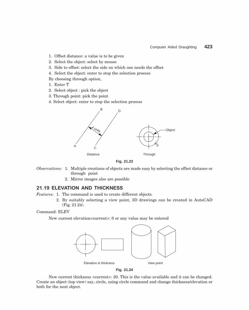
Computer Aided Draughting 423
dharmd:\N-Design\Des21-1.pm5
1. Offset distance: a value is to be given2. Select the object: select by mouse3. Side to offset: select the side on which one needs the offset4. Select the object: enter to stop the selection processBy choosing through option,1. Enter T2. Select object : pick the object3. Through point: pick the point4. Select object: enter to stop the selection process
B D
A C
4 units Object
p
Distance Through
Fig. 21.23
Observations: 1. Multiple creations of objects are made easy by selecting the offset distance orthrough point
2. Mirror images also are possible
����8� �-��0���� 0��� �2 ���//
Features: 1. The command is used to create different objects.2. By suitably selecting a view point, 3D drawings can be created in AutoCAD
(Fig. 21.24).
Command: ELEV
New current elevation<current>: 0 or any value may be entered
Elevation & thickness View point
Fig. 21.24
New current thickness <current>: 20. This is the value available and it can be changed.Create an object (top view) say, circle, using circle command and change thickness/elevation orboth for the next object.
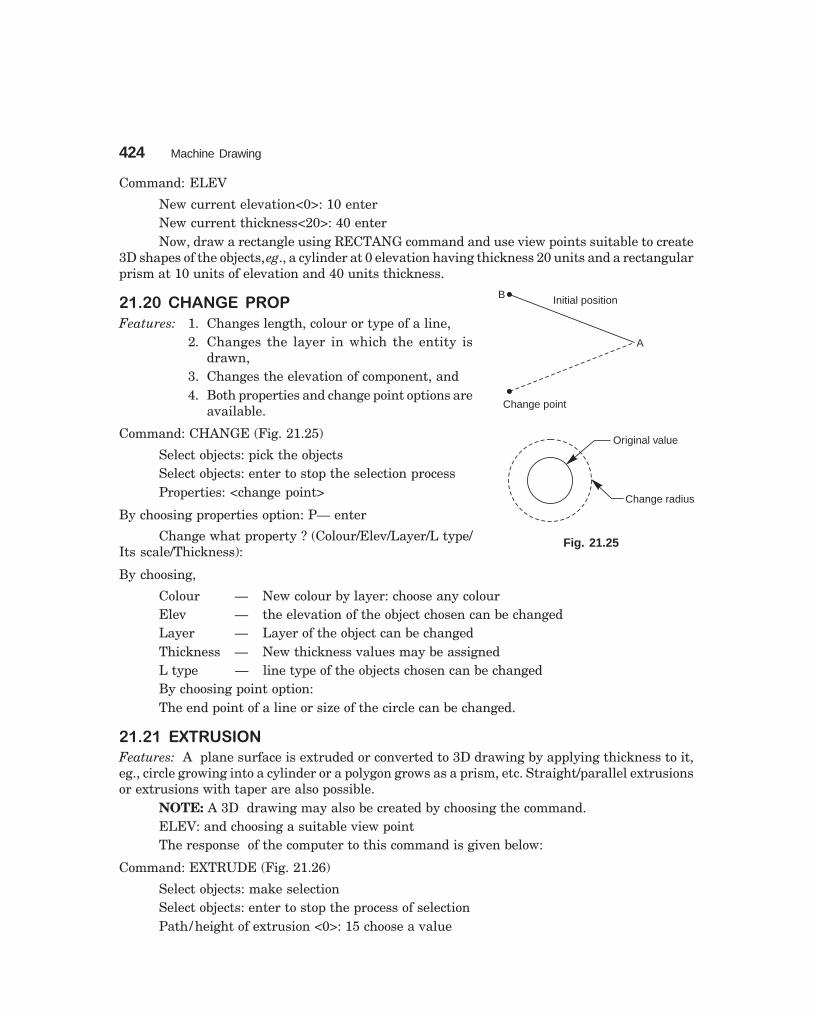
424 Machine Drawing
dharmd:\N-Design\Des21-1.pm5
B
A
Change point
Original value
Change radius
Initial position
Command: ELEV
New current elevation<0>: 10 enterNew current thickness<20>: 40 enterNow, draw a rectangle using RECTANG command and use view points suitable to create
3D shapes of the objects, eg., a cylinder at 0 elevation having thickness 20 units and a rectangularprism at 10 units of elevation and 40 units thickness.
����=� 20�3�� ����
Features: 1. Changes length, colour or type of a line,2. Changes the layer in which the entity is
drawn,3. Changes the elevation of component, and4. Both properties and change point options are
available.
Command: CHANGE (Fig. 21.25)
Select objects: pick the objectsSelect objects: enter to stop the selection processProperties: <change point>
By choosing properties option: P— enter
Change what property ? (Colour/Elev/Layer/L type/Its scale/Thickness):
By choosing,
Colour — New colour by layer: choose any colourElev — the elevation of the object chosen can be changedLayer — Layer of the object can be changedThickness — New thickness values may be assignedL type — line type of the objects chosen can be changedBy choosing point option:The end point of a line or size of the circle can be changed.
������ �@�� /��
Features: A plane surface is extruded or converted to 3D drawing by applying thickness to it,eg., circle growing into a cylinder or a polygon grows as a prism, etc. Straight/parallel extrusionsor extrusions with taper are also possible.
NOTE: A 3D drawing may also be created by choosing the command.ELEV: and choosing a suitable view pointThe response of the computer to this command is given below:
Command: EXTRUDE (Fig. 21.26)
Select objects: make selectionSelect objects: enter to stop the process of selectionPath/ height of extrusion <0>: 15 choose a value
Fig. 21.25

Computer Aided Draughting 425
dharmd:\N-Design\Des21-1.pm5
Extrusion taper angle <0>: by default or choose a valueNow, select a suitable view point for 3D images of the chosen objects.
Object selected V-point after extrusion
Fig. 21.26
OBJECTIVE QUESTIONS
1. What is CAD?2. Graphics can be converted into hard copy with a _________3. What is Graphic's package?4. Computer aided graphics systems have 3 major components. What are they ?5. What is digitizer?6. What are the applications of locators and selectors?7. Two example of single user operating systems are _________ and _________.8. Two examples of multi-user operating systems are _________ and _________.9. DOS is used on _________ computers.
10. Two types of DOS commands are_________ and _________.11. What do you understand by drawing limits and extents?12. What is layering concept?13. How do you begin a new drawing?14. How do you select an existing drawing for editing?15. How to exit from AutoCAD?16. Zooming shrinks the drawing. (True / False)17. Panning changes the magnification of the drawing.(True / False)18. Use of editing facilities of AutoCad:_________ ____________________ _______19. AutoCAD editor screen has_________areas. What are they?20. What is a status line?21. In AutoCAD 14 _________ _________ helps to set-up a drawing.22. In release 14,_________ provide introduction to the methods for starting a new drawing.23. ________command constrains the lines drawn horizontal and vertical directions only.24. _________command sets increments for cursor movements.25. Grid command helps the user by _________ _________ _________.

426 Machine Drawing
dharmd:\N-Design\Des21-1.pm5
26. Help can be obtained by —————— command.27. _________ command saves the work.28. List 4 important options of zoom command.29. Object selection is achieved by _________ and_________30. List 5 important edit commands and mention their applications.31. List the utility commands.32. Differentiate between DIM and DIMI commands.33. List the categories of dimensioning commands.34. Distinguish between Normal, Outer-most and Ignore styles of hatch command.35. When do you use PLOT and PRPLOT commands?36. Explain how a line can be drawn by (i) Cartesian coordinate method. (ii) Incremental
form and (iii) Polar coordinate form.37. How to draw an ellipse? Explain.38. Give the procedure for describing a polygon of 7 sides of side 30 mm.39. What are the various modelling techniques on ACAD?40. What do you understand by VPOINT command?41. What is VIEW PORTS?42. What are the options available on VIEWPORTS command?43. Which option is chosen to know the number and co-ordinates of current view port?44. How do you draw a cylinder, cone and box?45. What are the applications of primitives?46. When do you choose the command PLINE?47. What is the response of a computer for the command OFFSET?48. What are the features of the command Elev and thickness?49. Explain the features of CHANGE PROP command.50. What do you achieve by EXTRUSION command?51. List the various options available to draw an arc.52. What are the options available to draw a circle?53. Distinguish between 2 point and 3 point option of drawing a circle.54. List the various Boolean operations that may be performed on a computer.55. _________ operations can be used to create composite solids.56. Region command allows _________ _________ ___________ _________57. _________ allows to combine the volume of two or more solids into one.58. _________ allows to remove common area shared by two sets of solids.59. Intersect allows to create a composite solid that contains only ______ ______60. Mass prop provides ______ ______ for solid.61. Mass prop displays ______ ______ for regions.62. Solview command provides ______ ______ ______ ______ ______ ______63. Explain the functions of the command Isoplane.64. Explain the various dimensioning methods of AutoCAD.65. Distinguish between base line and continue commands.

Computer Aided Draughting 427
dharmd:\N-Design\Des21-1.pm5
66. List the various options available for the command DIM.67. Describe how do you make centre lines for an arc or circle.68. Solid modelling can be created by _________ a 2D object.69. _________ models are true shape 3D objects.70. Describe the responses of a computer for the command RECTANG.
ANSWER
2. Plotter/printer 4. (a) draughter, (b) hardware and (c) software7. MS-DOS, MS-Windows 95 8. UNIX, LINUX9. personal 10. internal, external
16. True 17. False19. four 21. Use Wizard22. instructions 23. ORTHO24. SNAP 25. creating reference lines26. HELP 27. SAVE29. Pick box, Window option 55. Boolean56. to create 2D enclosed areas 57. Union58. Subtract 59. common volume of two or more overlapping solids.60. volumetric information 61. area properties62. multi and sectional view drawings 68. extruding69. Solid

�������������� ��
Choose the correct answer or fill in the blanks, for the objective questions given below:
������� �
1. Production drawing is also called _________.(a) Machine drawing (b) Working drawing
2. _________drawing is useful to know the overall dimensions of the assembled unit.(a) Schematic (b) Catalogue
3. Instruction manual drawing helps in _________.(a) Making spares (b) Location of parts
4. Machine shop drawing is provided with_________.(a) Actual dimensions (b) Dimensions with machining allowances
5. Exploded assembly drawing represents _________ .(a) Position of parts in the sequence of assembly(b) Assembly drawing
������� �
1. The drawing sheet nearer to foolscape paper is _________ .(a) A4 (b) A0
2. Only _________ method of projection is recommended by BIS.(a) First angle (b) Third angle
3. As far as possible dimensions should be placed _________ the view of the drawing.(a) Outside (b) Inside
4. Dimension line _________ be used as extension line.(a) Should (b) Should not
5. Projection and dimension lines are drawn as _________ lines.(a) Thick (b) Thin
6. When several arcs of same size are dimensioned _________ leaders are used.(a) Separate (b) Extended
7. A radius of 25 mm is indicated on the drawing as _________ .(a) R 25 (b) 25R.
8. In aligned and uni-directional method of dimensioning, horizontal dimension line is_________ for placing the dimension.(a) Broken (b) Not broken
9. Hatching lines are drawn at an angle of _________ to the axis or to the main outline of thesections.(a) 60° (b) 45° (c) 30°
428

Objective Questions 429
dharmd:\N-Design\Des22-1.pm5
10. The size of the letters must be constant irrespective of the size of the drawing (True/False).11. The centre line should end at the outline of the drawing (True/False).12. Dimensions may be marked from hidden lines (True/False).13. Extension lines should end at the dimension line (True/False).14. Dimension lines should not cross each other (True/False).15. Centre lines are drawn in thick lines (True/False).16. Leader lines are drawn in thick lines (True/False).17. While drawing hidden lines, begin with a dash, not with a space (True/False).18. Invisible arcs begin with a space (True/False).19. Invisible small arcs may be made solid (True/False).20. Two axes intersect at short dashes (True/False).21. Leader line terminating within the outline of an object is indicated by a dot (True/False)22. The thickness of the line of a letter with 14 mm height in B type lettering is 1 mm (True/
False).23. Hatching is interrupted for dimensioning (True/False).24. Cutting plane is shown as thick continuous line (True/False).25. The smallest drawing sheet is designated as _________ .26. As per the latest BIS, SP:46-1988, _________ method of projection is to be used for drawing.27. The standard size of title block is _________.28. Each feature shall be dimensioned _________ only on a drawing.29. As far as possible dimensions should be expressed in _________ unit only.30. Dimensions should be taken from _________ lines.31. _________ of projection lines and dimension lines should be avoided.32. Where space is limited, arrow heads are replaced by _________ .33. Dimension lines, leader lines, projection lines and hatching lines are drawn as _________
lines.34. Centre lines are drawn as _________ .35. Visible lines and edges are drawn as _________ .36. The inclination of inclined lettering is _________ to the horizontal.37. Hidden lines are represented by _________ lines.38. Sectioned portion is represented by _________ lines.39. The length and width ratio of arrow head is _________ .40. Leader lines should be inclined to the horizontal at an angle greater than _________ degrees.41. In aligned dimensioning, the dimension is placed _________ the dimension line.42. For non-horizontal dimension, the dimension line is broken for _________ dimensioning
method.43. In aligned dimensioning, dimensions for non-horizontal lines are placed _________ the
dimension line.44. A _________ is placed below the dimension, when it is out of scale.45. In a situation where the dimensions are crowded, they should be shown as _________.46. Dimension notes are written in _________ letters and as per _________ abbreviations.47. The abbreviation SF stands for _________.
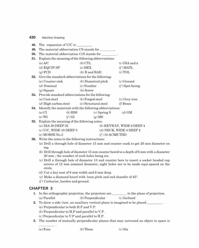
430 Machine Drawing
dharmd:\N-Design\Des22-1.pm5
48. The expansion of U/C is _________.49. The material abbreviation CS stands for _________.50. The material abbreviation CrS stands for _________ .51. Explain the meaning of the following abbreviations:
(a) A/C (b) CYL (c) DIA and φ(d) EQUIP-SP (e) HEX (f ) MATL(g) PCD (h) R and RAD (i) TOL
52. Give the standard abbreviations for the following:(a) Counter sink (b) Diametral pitch (c) Ground(d) Nominal (e) Number (f ) Spot facing(g) Square (h) Screw
53. Provide standard abbreviations for the following:(a) Cast steel (b) Forged steel (c) Grey iron(d) High carbon steel (e) Structural steel (f) Brass
54. Identify the materials with the following abbreviations:(a) CI (b) HSS (c) Spring S (d) GM(e) WI (f ) GI (g) MS
55. Explain the meaning of the following notes:(a) DIA 30 DEEP 25 (b) KEYWAY, WIDE 8 DEEP 4(c) U/C, WIDE 10 DEEP 5 (d) NECK, WIDE 4 DEEP 2(e) MORSE No.2 (f ) 10 ACME THD
56. Write the notes to the following instructions:(a) Drill a through hole of diameter 15 mm and counter sunk to get 20 mm diameter on
top.(b) Drill through hole of diameter 15 mm counter bored to a depth of 6 mm with a diameter
20 mm ; the number of such holes being six.(c) Drill a through hole of diameter 13 and counter bore to insert a socket headed cap
screws of 12 mm nominal diameter, eight holes are to be made equi-spaced on thecircle.
(d) Cut a key seat of 8 mm width and 6 mm deep.(e) Make a diamond knurl with 1mm pitch and end chamfer of 45°.(f ) Carburise, harden and ground.
������� �
1. In the orthographic projection, the projectors are _________ to the plane of projection.(a) Parallel (b) Perpendicular (c) Inclined
2. To draw a side view, an auxiliary vertical plane is imagined to be placed _________ .(a) Perpendicular to both H.P and V.P.(b) Perpendicular to H.P and parallel to V.P.(c) Perpendicular to V.P and parallel to H.P.
3. The number of mutually perpendicular planes that may surround an object in space is_________ .(a) Four (b) Three (c) Six

Objective Questions 431
dharmd:\N-Design\Des22-1.pm5
4. In the third angle projection, the object is imagined to be placed _________ .(a) Below H.P and behind V.P. (b) Above H.P and infront of V.P.(c) Above H.P and behind V.P.
5. In the first angle projection, the view obtained on the auxiliary vertical plane (AVP) placedto the right of the object is called _________ .(a) View from the left (b) View from the right(c) View from below.
6. In the third angle projection, to obtain the view from left, the AVP is assumed to be on the_________ of the object.(a) Right side (b) Left side (c) Top.
7. In _____ _____ projection, any view is so placed that it represents the side of the objectaway from it.
8. In _____ _____ projection, any view is so placed that it represents the side of the objectnearer to it.
9. A surface of an object appears in its true shape when it is _________ to the plane ofprojection.
10. The view from above of an object is obtained as a projection on the _________ plane bylooking the object normal to its _________ surface.
11. The view from the front of an object is obtained as a projection on the _________ plane bylooking the object _________ to its front surface.
12. In first angle projection:(a) The view from above is _________ the view from the front.(b) The view from the right is placed on the _____ _____ of the view from the front.
13. In the third angle projection :(a) The view from above is _________ the view from the front.(b) The view from the left is placed on the _________ of the view from the _________ .
14. The side view of an object is obtained as a projection on the _________ plane by looking theobject _________ to its _________ surface.
15. The number of views required for an object depends on its _________ .16. In the first angle projection, the object is positioned in-between the observer and the plane
of projection (True/False).17. In the third angle projection, the object is positioned in-between the observer and the plane
of projection (True/False).18. In both the methods of projection, the views are identical in shape and detail (True/False).19. The location of different views w.r.t. the view from the front is different in both the methods
of projection (True/False).20. In the first angle projection, the object is imagined to be placed above the H.P and behind
V.P (True/False).
������� �
1. Sectional views reveal _________ .(a) Inner details (b) External features(c) Overall size of the object

432 Machine Drawing
dharmd:\N-Design\Des22-1.pm5
2. To obtain full section, _____ _____ of the object is imagined to be removed.(a) One fourth (b) One third (c) One half
3. In half sectional view, _____ _____ of the object is imagined to be removed.(a) One half (b) One fourth (c) One third
4. _________ and _________ should not be shown in section.(a) Web (b) Key(c) Shaft along axis (d) Shaft across the axis
5. Pulley arms are shown as revolved sections (True/False).6. Rivet sectioned across is not hatched (True/False).7. Rivet sectioned along the length is hatched (True/False).8. Fasterners are not hatched in longitudinal sections (True/False).9. In drawing, sectioned view of a right hand internal thread appears as left hand thread
(True/False).
������� �
1. A thread is specified by _____ _____ and _________.2. _________ is the distance measured parallel to the axis between corresponding points on
adjacent threads.3. _________ is the distance the screw advances axially in one turn.4. Pitch and lead are equal in _____ _____ threads, however it is not the same in _________
threads.5. _________ thread is used in brass pipe work.6. _________ thread profile has rounded ends.7. For transmitting power in one direction _________ thread is used.8. _________ thread is used for transmitting high power.9. _________ thread is stronger than square thread.
10. _________ thread is used in the screw Jack.11. _________ thread is used on the lead screw of a lathe.12. _________ thread is used on the shaft for transmitting power to worm wheels.13. _________ is the included angle of ISO metric screw thread.14. In the metric screw thread, basic profile is rounded at the _________ diameter of external
thread and _________ diameter or internal thread.15. In double start threads, pitch is equal to _________ of lead.16. Threads are specified as coarse or fine based on _________ value.17. In conventional representation of threads, the root diameter is represented by _____ _____
circle.18. Both left and right hand threads are used in _____ _____.19. For coarse thread, there is only one standard pitch (True/False).20. The size across flats in a hexagonal nut is _________.
(a) 1.5D (b) 0.9D (c) 1.5D + 3 (d) 1.2D21. The angle of a metric thread is _________.
(a) 55° (b) 45° (c) 47 1/2° (d) 60°

Objective Questions 433
dharmd:\N-Design\Des22-1.pm5
22. The angle of an ACME thread is _________ degrees.(a) 48 (b) 90 (c) 29 (d) 45
23. The distance across corners of a hexagonal nut is equal to _________.(a) 2D (b) 1.5D (c) 1.2D
24. The angle of worm thread is _________ degrees.(a) 45 (b) 29 (c) 55
25. The angle of a buttress thread is _________ degrees.(a) 90 (b) 50 (c) 45 (d) 29
26. In conventional representation of external thread in section, the hatching is extended uptothe core diameter (True/False).
27. In conventional representation of internal thread in section, the hatching is extended uptothe root (major) diameter (True/False).
28. The height of hexagonal nut is _________.(a) D (b) 1.1D (c) 1.3D
29. In conventional sectioned representation of threads in engagement, hatching is extendedupto core diameter of the bolt and its nominal diameter is shown as continuous line (True/False).
30. A washer is used for adjusting the height of the bolt (True/False).31. _________ neck is used to prevent the rotation of the bolt.32. _________ bolt is used for lifting heavy machinery.33. Stud bolt has threads to full length (True/False).34. The thickness of locknut is more than the standard nut (True/False).35. _________ nut is used to protect the bolt end from damages.36. A screw has threads to full length (True/False).37. A bolt has threads to full length (True/False).38. Cap screws are smaller in size when compared to machine screws (True/False).39. _________ is used to tighten socket headed screws.40. Set-screws are used only for transmitting very light loads (True/False).41. Grub screw is a cap screw (True/False).42. _________ locknut is used in automobile works.43. A spring washer is used to adjust the height of the nut (True/False).44. _________ foundation bolt is common and simple.45. _________ is used in Lewis foundation bolt.46. _________ is used in cotter foundation bolt.
������� �
1. A key is a temporary joint (True/False).2. A cotter is a permanent joint (True/False).3. Pin joints may be temporary or permanent joints (True/False).4. The standard taper on the face of a key is _________.5. Taper sunk key is tapered on both sides (True/False).6. Saddle keys are used for light duties (True/False).

434 Machine Drawing
dharmd:\N-Design\Des22-1.pm5
7. Sunk keys are used for light duties (True/False).8. Woodruff key is a type of sunk key (True/False).9. Feather key is a sunk key with uniform width and thickness (True/False).
10. Feather keys are used with _________.(a) Gears (b) Flywheel (c) Pulleys.
11. _________ fit exists between feather key and keyway.12. A knuckle joint is a _________ joint used to fasten two circular rods.13. Knuckle joints are used in _________ links.14. A cotter of rectangular cross-sections has uniform thickness/width, however it is varying
in width/thickness.15. A cotter joint with a jib is used to join two circular rods (True/False).16. Pin joints fasten two rods under axial loads (True/False).17. A knuckle joint is used to fasten two square rods (True/False).
������� �
1. Rigid couplings are used for shafts which are _________.(a) Slightly mis-aligned (b) Inclined (c) Co-axial
2. In a butt or half-lap coupling, the sleeve is normally fitted to the shafts by means of_____ _____.(a) Saddle key (b) Feather key (c) tight fit
3. In split-muff couplings, the number of bolts will always be _________.(a) Even (b) Four (c) Odd
4. In the solid flanged couplings, the flange is _________.(a) Separate, mounted using a sunk key(b) Integral with the shaft(c) Fitted with interference fit
5. In flanged coupling, the flanges are joined together by means of _________.(a) Hex. headed bolts (b) Headless taper bolts (c) Key
6. In solid flanged coupling, the flanges are joined by means of _________.(a) Hex. headed bolts (b) Headless taper bolts (c) Cotter pin
7. For ensuring correct alignment; in flanged coupling _________ is provided.8. A coupling is called protected flanged coupling because _ _ _ _ _ .9. Shaft couplings are permanent in nature (True/False).
10. Shaft couplings are used only to take axial loads (True/False).11. A universal coupling connects two shafts, only when the angle between them is very small
(True/False).12. An Oldham coupling connects two shafts, when they are _________.
(a) Intersecting (b) Parallel (c) Coaxial13. The inevitable bearing wear is taken care of in _________ _________ .
(a) Rigid couplings (b) Dis-engaging couplings (c) Flexible couplings14. Relative rotation between the shafts in bushed-pin type flanged coupling is taken
care of by _____ _____.

Objective Questions 435
dharmd:\N-Design\Des22-1.pm5
15. Mis-alignment of shafts in compression coupling is taken care of by _____ _____ _____ .17. When the power transmission from one shaft to another is intermittent, _________ coupling
is used.18. The power is transmitted in cone coupling by _________, whereas in claw coupling, by
_________.19. Non-aligned couplings are used to transmit power between two shafts which are _____
_____ .20. Non-aligned _________ coupling is recommended for connecting intersecting shafts.21. Oldham coupling is recommended to connect two _________ shafts.22. Flexibility in cushion coupling is provided by _____ _____ .
������� �
1. In joints for CI pipes, the flanges are not integral with the pipe lines (True/False).2. Socket and spigot joints are used for connecting underground pipe lines (True/False).3. For high pressure application, the pipe is strengthened by _ _ _ _ _ .4. For larger diameter pipes, the flanges are strengthened by _________.5. In copper pipes, flanges are _________.
(a) Integral with pipe (b) Brazed to the pipe (c) Keyed to the pipe6. For solid drawn WI or steel pipes, the flanges are _________.
(a) Screwed (b) Keyed (c) Brazed7. _____ _____ joint is used on pipes which can not be connected using a coupler.8. _____ _____ facilitates making and breaking of the joints, without disturbing the pipe
layout.9. _________ joints are used to accomodate expansion or contraction due to variation of fluid
temperature.10. _ _ _ _ _ is placed between two pipes to act as expansion joint.11. __________ packing prevents the leakage in stuffing boxes.12. When expansion joint is used, the pipes are __________.
(a) Rigidly clamped (b) Supported on rollers13. Elbows, Tees and crosses are used to connect or branch-off the pipes at _____ _____ .14. _____ _____ is used to connect two pipes of different diameter.15. __________ is used to close the end of a pipe.16. __________ is a small pipe, threaded throughout on the outside.17. With reference to pipe fitting, MTA stands for _____ _____ _____ .18. With reference to pipe fitting, FTA stands for _____ _____ _____.19. __________ is used to connect a PVC pipe line to a metal pipe.20. __________ is used to connect metal pipe and all types of valves, etc.21. __________ is the equivalent PVC pipe for half inch GI pipe.22. 50 mm is the equivalent PVC pipe for __________ GI pipe.23. PVC pipes are joined by __________ cement.

436 Machine Drawing
dharmd:\N-Design\Des22-1.pm5
������� �
1. _________ pulley is used to mount at an intermediate location on a shaft.2. Pulleys are mounted on shafts by __________keys.3. Pulley with grooves is used with __________ belts.4. Step cone pulleys are mounted on driver and driven shafts in __________ directions.5. Different belts are used on the pairs of steps of cone pulleys (True/False).6. When a number of machines are operated from a single power source, each one is provided
with a _____ _____ _____ pulley arrangement.7. __________ belts are preferred when shafts are nearer to each other.8. __________ belts are used when centre distance between two shafts is more.9. Loose pulley is used to transmit the power (True/False).
10. Diameter of the loose pulley is slightly less than that of the fast pulley (True/False).11. __________ cause less pull on the shaft for the same amount of power transmission.12. __________ is used for transmission of power over large distances.
������� ��
1. Riveted joints are permanent joints (True/False).2. ________ and __________ is done to make the riveted joint air tight.3. Width of the fullering tool is _____ _____ width of the bevelled edges of the plate.
(a) equal to (b) less than (c) greater than4. Width of the caulking tool is _____ _____ width of the bevelled edges of the plate.
(a) equal to (b) less than (c) greater than5. In chain riveting, adjacent rows are placed directly opposite to each other (True/False).6. In zig-zag riveting, the rivets in adjacent rows are placed directly opposite to each other
(True/False).7. ________ is the distance from the edge of the plate to the centre of the nearest rivet.8. Pitch is the distance between the centres of the adjacent rivets in the same row (True/
False).9. The distance between the centre of a rivet in a row to the next rivet in the adjacent row in
zig-zag riveting is called __________ .10. Lap joints are classified based on number of rows of rivets (True/False).11. The cover plate in a butt joint is called __________ .12. The plates are bevelled in __________ joint.13. The two plates are square in __________ joint.14. Straps are bevelled (True/False).15. ________ joints are used for joining thick plates.16. In single strap butt joint, the thickness of the strap is __________ than the main plate.17. In double strap butt joint, the thickness of the straps is __________ than the main plate.18. Two cover plates are used in making a lap joint (True/False).19. Riveting produces a __________ joint.
(a) Flexible (b) rigid (c) dis-engaging type.

Objective Questions 437
dharmd:\N-Design\Des22-1.pm5
������� ��
1. Welding produces a __________ joint.(a) Temporary (b)Permanent
2. A circle at the elbow of the welding symbol indicates __________.3. Welding on site is indicated by __________ at the elbow.4. In the process of welding, SAW stands for _____ _____ _____.5. Welding symbol on the continuous line represents _ _ _ _ _ .6. Welding symbol placed on the dashed line represents _ _ _ _ _ .7. Length of the weld is indicated on the __________ side of the weld symbol.8. __________ is the welding symbol with machining finish.9. Welding symbol with grinding finish is represented by __________.
10. __________ is the welding process designation for oxy-acetylene welding.11. Carbon arc welding is represented by __________ .12. If a weld is to have a flat finish, __________ should be added above the symbol.
������� ��
1. Journal bearings can support only _____ _____.(a) axial loads (b) radial loads (c) inclined loads
2. Thrust bearings are mainly used to resist radial loads (True/False).3. A pivot bearing is used for horizontal shafts (True/False).4. A collar thrust bearing is generally used on horizontal shafts (True/False).5. Bearings are classified into __________ and __________ categories.6. In a journal bearing, the load is in __________ direction to the shaft axis.7. __________ bearing is used for long shafts requiring intermediate support.8. Snug is provided to the brasses to prevent __________.9. Hangers are used to support line shafts (True/False).
10. ________ bearing supports a shaft running parallel to a wall.11. The size of the wall bracket depends on the biggest size of the pulley mounted on the shaft
(True/False).12. The size of the pillar bracket depends on the size of the pulley mounted on the shaft (True/
False).13. Ball bearings are used to resist axial loads on shafts (True/False).14. Roller bearings are used to resist normal loads acting on shafts (True/False).15. The bearing designation 308 represents _ _ _ _ _ .16. Locking washer is used to prevent the __________ movement of the bearing.
������� �
1. Chains are positive drive machine elements (True/False).2. Gears are positive drive power transmission machine elements (True/False).3. _________ chains are used for bicycles.4. Inverted tooth chains are also called silent chains (True/False).5. The distance between the centres of the articulating joints is called _________.6. Smaller sprockets are known as _________ .

438 Machine Drawing
dharmd:\N-Design\Des22-1.pm5
7. The chain consists of integer number of pitches with _________ number preferably.(a) Odd (b) Even
8. Gears are used for power transmission from one shaft to another, when the centre distancebetween them is _________.(a) small (b) large
9. A module is always expressed in _________.(a) mm (b) cm
10. Helical gears are used to connect _________ shafts.(a) Non-parallel (b) Parallel
11. A herring bone gear is a _________ gear.12. The rack and pinion arrangement is used to transform rotary motion into translatory
motion but not vice versa (True/False).13. The addendum is equal to module in spur gears (True/False).14. Worm gearing is used for speed reducers (True/False).15. _________ gearing is suitable for two shafts at 90°.
������� ��
1. A fixture is used to guide the tool (True/False).2. A jig is used to guide the tool (True/False).3. A workpiece is represented in _____ _____ lines in jig or fixture drawing.4. In jigs and fixtures drawing, workpiece is considered as transparent (True/False).5. Workpiece location should prevent _________ degrees of motion.
(a) 6 (b) 3 (c) 46. The inside diameter of a drill bush is ground to a running fit _________.7. The outside diameter of a drill bush with press fit is _________.
(a) p6 (b) h6 (c) f68. _________ are provided to the fixture to locate it with respect to machine axis.9. _________ weight is provided on a turning fixture base.
10. To set the cutter, _________ block is provided on milling fixtures.
������� ��
1. The extreme permissible size for any dimension of a part is _________.(a) limit (b) nominal size (c) tolerance
2. Tolerance is denoted by number symbol followed by a letter symbol (True/False).3. Fundamental tolerances are given for letter symbols (True/False).4. Upper deviation for hole is indicated as EI (True/False).5. ES stands for E’cart _________.6. EI stands for E’cart _________.7. The algebraic difference between the maximum limit and nominal size is known as
_________ .(a) Deviation (b) Upper deviation (c) allowance
8. The grade of tolerance obtained by centre lathe turning is _________.9. Honing produces the tolerance grade of _________.
(a) 10 (b) 15 (c) 6 (d) 0

Objective Questions 439
dharmd:\N-Design\Des22-1.pm5
10. In unilateral tolerance, the limits will be on _____ _____ of the basic size.11. In bilateral tolerance, the limits are on _____ _____ of the basic size.12. _________ basis system of fits are normally used.13. In hole basis system, the lower deviation is _________ for the letter symbol H.14. Shaft basis system is preferred in _________ industries.
(a) Textile (b) Automobile (c) Aircrafts15. If the allowance is positive, it results in _____ _____.
(a) Clearance fit (b) interference fit16. If the allowance is negative, the fit is _________.
(a) Interference (b) Clearance (c) Transition17. For shrink fit with a hole of H8, the shaft tolerance is given by _________.
(a) n6 (b) c7 (c) U818. A clearance fit is obtained from _________.
(a) H7/n6 (b) H7/g6 (c) H7/m619. The fit recommended on shaft for ball bearing mounting is _________.
(a) H7/g6 (b) H7/f6 (c) H7/m620. The fundamental deviations are given in _________ units.21. Fundamental tolerance of a shaft of size 30 mm for grade 6 is _________.22. Fundamental deviation of shaft of size 18 mm and letter symbol ‘f ’ is _________.23. Lower deviation of a hole of size 30 H7 is _________.24. The lower deviation of 30m6 is _________.25. The upper deviation of 30m6 is _________.
������� ��
1. Higher the smoothness of the surface, better is the corrosion resistance (True/False).2. With better surface finish, friction between mating parts is not reduced (True/False).3. Surface roughness is indicated by _________.
(a) Rt (b) Ra4. Surface flatness is measured by _________.
(a) Micrometer (b) Feeler guage (c) Optical flat5. Roughness value Ra is given in _________ units.6. The Ra value for turning is _________ to _________.7. The Ra value for honing is _________.
(a) 0.025 (b) 0.4 (c) 0.0158. The roughness value for lapping is _________.
(a) 0.012 (b) 0.06 (c) 0.049. The roughness value for super finishing is _________ to _________.
10. The roughness value for forging is _________ to _________.11. The roughness grade for 50 µm is _________.12. The roughness value for grade N2 is _________.13. Lay indicates the surface finish pattern (True/False).14. Two triangles indicate _________ _________.
(a) Fine finish (b) Rough finish

440 Machine Drawing
dharmd:\N-Design\Des22-1.pm5
��� �!�
������� �
1. (b) 2. (b) 3. (b) 4. (a) 5. (a)
������� �
1. (a) 2. (a) 3. (a) 4. (b) 5. (b) 6. (a) 7. (a) 8. (b) 9. (b) 10. F 11. F 12. F 13. F 14. T 15. F 16. F 17. T18. F 19. T 20. F 21. T 22. F 23. T 24. F 25. A4 26. First angle 27. 170 × 65 28. once 29. mm 30.visible 31. Crossing 32. dotes 33. thin 34. Thin lines 35. Thick lines 36. 75° 37. dotted 38. hatching39. 3:1 40.30 41. above 42. Uni-directional 43. along 44. dash 45. Staggered 46. Capital, standard47. Spot facing 48. undercut 49. cast steel 50. Chromium steel 51. (a) Across corners (b) cylinder(c) Diameter (d) Equi-space (e) Hexagonal (f ) Material (g) Pitch circle diameter (h) Radius (i)Tolerance 52. (a) CSK (b) DP (c) GND (d) NOM (e) NO (f) SF (g) SQ (h) SCR 53. (a) CS (b) FS (c)Grey I (d) HCS (e) ST (f) BRASS 54. (a) cast iron (b) High speed steel (c) spring steel (d) Gun metal(e) Wrought iron (f) Galvanised iron (g) Mild steel 55. (a) Diameter of 30 mm with 25 mm depth (b)key way of 8 mm width and 6 mm depth (c) Under cut of width 10 mm and depth 5 mm (d) Neckof width 4 mm and depth 2 mm (e) Morse taper 2 (f ) ACME thread of 10mm nominal diameter 56.(a) DRILL DIA 15 CSK 20 (b) 6 HOLES, DIA 15 C' BORE DIA 20 DEEP 6 (c) 8 HOLES, DIA 13EQUIP-SP C'BORE FOR M12 SOCKET HD CAP SCR (d) KEYSEAT WIDE 8, DEEP 6 (e)DIAMOND KNURL 1 RAISED 45° (f ) CARB, HDN AND GND
������� �
1. (b) 2. (a) 3. (c) 4. (a) 5. (a) 6. (b) 7. First angle 8. Third angle 9. Parallel 10. Horizontal, top11. Vertical, normal 12. (a) below (b) left side` 13. (a) below (b) left, front 14. Profile, Normal, side15. Complexity 16. True 17. False 18. True 19. True 20. False
������� �
1. (a) 2. (c) 3. (b) 4. (a, c) 5. True 6. False 7. False 8. True 9. True
������� �
1. Nominal diameter, pitch 2. Pitch 3. Lead 4. Single start, multi-start 5.Sharp V 6. BSW 7.Buttress 8. Square 9. ACME 10. Square 11. ACME 12. Worm 13. 60° 14. Minor, major 15. Half16. Pitch 17. Thin, incomplete 18. Coupler nut 19. True 20. (c) 21. (d) 22. (c) 23. (a) 24. (b) 25. (a)26. True 27. True 28. (a) 29. True 30. False 31. Square 32. Eye 33. False 34. False 35. Cap ordome 36. True 37. False 38. False 39. Allen key 40. Ture 41. False 42. Castle 43. False 44. eye 45.Key 46. Cotter
������� �
1. True 2. False 3. False 4. 1:100 5. False 6. True 7. False 8. True 9. True 10. (a) 11. Clearance 12.Pin 13. Suspension 14. Thickness, width 15. False 16. False 17. False
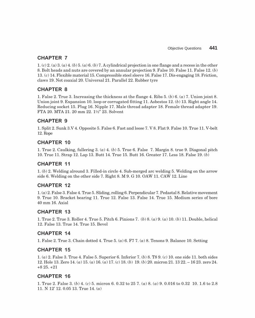
Objective Questions 441
dharmd:\N-Design\Des22-1.pm5
������� �
1. (c) 2. (a) 3. (a) 4. (b) 5. (a) 6. (b) 7. A cylindrical projection in one flange and a recess in the other8. Bolt heads and nuts are covered by an annular projection 9. False 10. False 11. False 12. (b)13. (c) 14. Flexible material 15. Compressible steel sleeve 16. False 17. Dis-engaging 18. Friction,claws 19. Not coaxial 20. Universal 21. Parallel 22. Rubber tyre
������� �
1. False 2. True 3. Increasing the thickness at the flange 4. Ribs 5. (b) 6. (a) 7. Union joint 8.Union joint 9. Expansion 10. loop or corrugated fitting 11. Asbestos 12. (b) 13. Right angle 14.Reducing socket 15. Plug 16. Nipple 17. Male thread adapter 18. Female thread adapter 19.FTA 20. MTA 21. 20 mm 22. 1½″ 23. Solvent
������� �
1. Split 2. Sunk 3.V 4. Opposite 5. False 6. Fast and loose 7. V 8. Flat 9. False 10. True 11. V-belt12. Rope
������� ��
1. True 2. Caulking, fullering 3. (a) 4. (b) 5. True 6. False 7. Margin 8. true 9. Diagonal pitch10. True 11. Strap 12. Lap 13. Butt 14. True 15. Butt 16. Greater 17. Less 18. False 19. (b)
������� ��
1. (b) 2. Welding alround 3. Filled-in circle 4. Sub-merged arc welding 5. Welding on the arrowside 6. Welding on the other side 7. Right 8. M 9. G 10. OAW 11. CAW 12. Line
������� ��
1. (a) 2. False 3. False 4. True 5. Sliding, rolling 6. Perpendicular 7. Pedastal 8. Relative movement9. True 10. Bracket bearing 11. True 12. False 13. False 14. True 15. Medium series of bore40 mm 16. Axial
������� ��
1. True 2. True 3. Roller 4. True 5. Pitch 6. Pinions 7. (b) 8. (a) 9. (a) 10. (b) 11. Double, helical12. False 13. True 14. True 15. Bevel
������� ��
1. False 2. True 3. Chain dotted 4. True 5. (a) 6. F7 7. (a) 8. Tenons 9. Balance 10. Setting
������� ��
1. (a) 2. False 3. True 4. False 5. Superior 6. Inferior 7. (b) 8. T8 9. (c) 10. one side 11. both sides12. Hole 13. Zero 14. (a) 15. (a) 16. (a) 17. (c) 18. (b) 19. (b) 20. micron 21. 13 22. – 16 23. zero 24.+8 25. +21
������� ��
1. True 2. False 3. (b) 4. (c) 5. micron 6. 0.32 to 25 7. (a) 8. (a) 9. 0.016 to 0.32 10. 1.6 to 2.811. N 12’ 12. 0.05 13. True 14. (a)

��������
Table 1 Tensile properties of standard steels
σUt σYNew Designation Old DesignationN mm/ 2 N mm/ 2
Fe 290 (St 30) 290 170FeE 220 — 290 220Fe 310 (St 32) 310 180Fe 230 — 310 230Fe 330 (St 34) 330 200FeE 250 — 330 250Fe 360 (St 37) 360 220FeE 270 — 360 270Fe 410 (St 42) 410 250FeE 310 — 410 310Fe 490 (St 50) 490 290FeE 370 — 490 370Fe 540 (St 55) 540 320FeE 400 — 540 400Fe 620 (St 63) 620 380FeE 460 — 620 460Fe 690 (St 70) 690 410FeE 520 — 690 520Fe 770 (St 78) 770 460FeE 580 — 770 580Fe 870 (St 88) 870 520FeE 650 — 870 650
Table 2 Tensile properties of carbon steels (unalloyed) (stress values in N/mm2)
Condition Hot rolled or Cold drawn Hardened and Cast hardenednormalised (20 to 40 mm dia) tempered refined and
quenchedDesignation (core properties)
New Old σUt σUt σUt σUt
7C4 C07 320–40010C4 C10 340–420 450 50014C6 Cl4 370–450 50015C8 C15Mn75 420–500 510 50020C8 C20 440–520 510 50025C8 C25Mn75 470–57030C8 C30 500–600 570 60035C8 C35Mn75 550–650 60040C8 C40 580–680 610 70050C4 C50 600–780 630 800
NOTE—Yield stress may be taken as 55 to 65% of ultimate stress unless otherwise specified.
442

Annexure 443
dharmd:\N-Design\Des23-1.pm5
Table 3 Recommended heat treatment data for carbon and alloy steels
Hot workingDesignation of temperature Normalising Hardening Quenching Tempering
steel °C °C °C °C
30C8 1200–850 860–890 860–890 Water or oil 550–66035C8 1200–850 850–880 840–880 Water or oil 530–76040C8 1200–850 830–860 830–860 Water or oil 550–66045C8 1200–850 830–860 830–860 Water or oil 530–67050C8 1150–850 810–840 810–840 Oil 550–66055C8 1150–850 810–840 810–840 Oil 550–66040C10S18 1200–850 830–860 830–860 Oil 550–66040Mn2S12 1200–850 840–870 840–870 Oil 550–66020C15 1200–850 860–900 860–900 Water or oil 550–66027C15 1200–850 840–880 840–880 Water or oil 550–66037C15 1200–850 850–870 850–870 Water or oil 550–66040Cr4 1200–850 850–880 850–880 Oil 550–70035Mn6Mo3 1200–900 — 840–860 Water or oil 550–60035Mn6Mo4 1200–900 — 840–860 Oil 550–66040Cr4Mo3 1200–850 850–880 850–880 Oil 550–72040Cr13Mo10V2 1200–850 – 900–940 Oil 570–65040Cr7A110Mo2 1200–850 – 850–900 Oil 550–70040Ni14 1200–850 830–860 830–860 Oil 550–65035Ni10Cr3Mo6 1200–850 — 830–850 Oil Up to 66040Ni10Cr3Mo6 1200–850 — 830–850 Oil Up to 66040Ni6Cr4Mo2 1200–850 — 830–850 Oil 550–66040Ni6Cr4Mo3 1200–850 — 830–850 Oil 150–200 or
550–66035Ni3Cr5 1200–850 — 810–830 Air or Oil 250
Table 4 Hardness obtained by Induction/Flame hardening
Steel designation Hardness, HRC
C30 45–50C 35 Mn 75 51–57C 45 55–61C 55 57–6237 Mn 2 53–5947 Mn 2 54–6035 Mn 2 Mo 28 53–5940 Cr 1 54–6050 Cr 1 57–6250 Cr 1 V 23 57–6240 Cr 1 Mo 28 54–6040 Ni 3 54–6035 Ni 1 Cr 60 54–6040 Ni 2 Cr1 Mo 28 54–60

444 Machine Drawing
dharmd:\N-Design\Des23-1.pm5
Fin
e se
ries
Coa
rse
seri
es
Table 5 Dimensions for metric screw threads (mm)
Major Minor diameter Depth ofSize Pitchdiameter
Pitch diameterBolt Nut thread
M2.5 0.45 2.5 2.208 1.948 2.013 0.276M3 0.5 3 2.675 2.387 2.459 0.307M4 0.7 4 3.545 3.141 3.242 0.429M5 0.8 5 4.480 4.019 4.134 0.491M6 1 6 5.350 4.773 4.918 0.613M8 1.25 8 7.188 6.466 6.647 0.767M10 1.5 10 9.026 8.160 8.376 0.920M12 1.75 12 10.863 9.853 10.106 1.074M16 2 16 14.701 13.543 13.835 1.227M20 2.5 20 18.376 16.933 17.294 1.534M24 3 24 22.051 20.320 20.752 1.840M30 3.5 30 27.727 25.706 26.211 2.147M33 3.5 33 30.727 28.706 29.211 2.147M36 4 36 33.402 31.093 31.67 2.454
M8 × 1 1 8 7.350 6.773 6.918 0.613M10 × 1.25 1.25 10 9.188 8.466 8.647 0.767M12 × 1.25 1.25 12 11.188 10.466 10.647 0.767M16 × 1.5 1.5 16 15.026 14.16 14.376 0.920M20 × 1.5 1.5 20 19.026 18.16 18.376 0.920M24 × 2 2 24 22.701 21.546 21.835 1.227M30 × 2 2 30 28.701 27.546 27.835 1.227M36 × 3 3 36 34.051 32.32 35.752 1.840
Table 6 Tap drill sizes
Metric coarse threads British Standard Whitworth (BSW) threads
Size Pitch Max. minor Drill size size Threads per Max. minor Drill size(mm) (mm) diameter (mm) (inch) inch diameter (mm)
(mm) (mm)
1.4 0.3 1.165 1.1 1/16 60 1.231 1.21.6 0.35 1.321 1.25 3/32 48 1.910 1.851.8 0.35 1.521 1.45 1/8 40 2.590 2.552 0.4 1.679 1.6 5/32 32 3.211 3.2
2.2 0.45 1.838 1.75 3/16 24 3.744 3.72.5 0.45 2.138 2.05 7/32 24 4.538 4.53 0.5 2.599 2.5 1/4 20 5.224 5.1
3.5 0.6 3.010 2.9 5/16 18 6.661 6.54 0.7 3.422 3.3 3/8 16 8.052 7.9
4.5 0.75 3.878 3.7 7/16 14 9.379 9.25 0.8 4.334 4.2 1/2 12 10.610 10.56 1 5.153 5 9/16 12 12.176 127 1 6.153 6 5/8 11 13.598 13.58 1.25 6.912 6.8 3/4 10 16.538 16.59 1.25 7.912 7.8 7/8 9 19.411 19.25
10 1.5 8.676 8.5 1 8 22.185 2211 1.5 9.676 9.5 1 1/8 7 24.879 24.7512 1.75 10.441 10.2 1 1/4 7 28.058 2814 2 12.210 12 1 3/8 6 30.555 30.516 2 14.210 14 1 1/2 6 33.730 33.5
(Contd.)

Annexure 445
dharmd:\N-Design\Des23-1.pm5
Table 6 Tap drill sizes
Metric coarse threads British Standard Whitworth (BSW) threads
Size Pitch Max. minor Drill size size Threads per Max. minor Drill size(mm) (mm) diameter (mm) (inch) inch diameter (mm)
(mm) (mm)
18 2.5 15.744 15.5 1 5/8 5 35.921 35.520 2.5 17.744 17.5 1 3/4 5 39.096 3922 2.5 19.744 19.5 1 7/8 4 1/2 41.648 41.524 3 21.252 21 2 4 1/2 44.823 44.527 3 24.252 2430 3.5 26.771 26.533 3.5 29.771 29.536 4 32.270 3239 4 35.270 35
42 4.5 37.799 37.5
Table 7 Properties and uses of irons, plain-carbon steels and alloy steels
Material and approximate Tensile strengthcomposition (%) (Mpa)
Typical uses
Wrought iron Fe (almost pure) 340 Chain links, ornamental work, etc.Grey cast irons 170–350 Brackets, machine frames, pistons, cylinders,(3-4) C, (1.2-2.8) Si, pipes, pulleys, gears, bearings, slides, etc.(0.5-1) MnMalleable irons 280–510 Brake drums, levers, links, shafts, hinges,(2-3) C, (0.1-0.5) P, spanners, chains, wheels, vice bodies, etc.(0.5-6) S, (1-5) Si,(0.4-2.1) Ni, (0.1-5) CrSpheroidal-graphite (SG) irons 370–725 Machine frames, pump bodies, pipes, crankshafts,Nodular irons hand tools, gears dies, office equipment, etc.Low-carbon steels 430–480 Lightly stressed parts, nails, car bodies, chains,(up to 0.25) C rivets, wire, structural parts, etc.Medium-carbon steels 480–620 Axles, spindles, couplings, shafts, tubes gears,(0.25-0.6) C forgings, rails, hand tools, dies, ropes, keys, etc.High-carbon (tool) steels 620–820 Hammers, chisels, screws, drills, taps, dies, blades,(0.6-1.5) C punches, knives, chisels, saws, razors.Nickel steels 310–700 Axles, crankshafts, car parts, camshafts, gears,(0.1-4) C, (0.04-1.5) Mn, pins, pinions, etc.(1-5) NiStainless steels 650-900 Chemical plants, kitchen equipment, cutlery,(0.05-0.1) C, (0.8-1.5) Mn, springs, circlips, etc.(8.5-18) Ni, (12.5-18) CrLow-alloy nickel-chrome steels 930–1500 Highly stressed parts: conrods, shafts, gears,(1-5) Ni, (0.6-1.5) Cr driving shafts, crankshafts, etc.Manganese steels 700–850 Cutting tools, stone crushing jaws, dredging(0.35-1.2) C, (1.5-12.5) Mn equipment, press tools, railway crossings, etc.Heat-resisting steel 690 Components exposed to high temperatures, etc.(0.1) C, (1.5) Si , (1) Mn,(19) Cr, (1) Ni
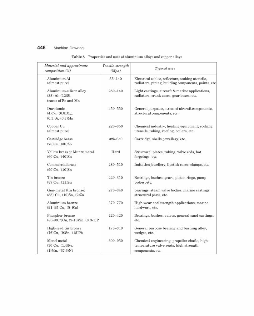
446 Machine Drawing
dharmd:\N-Design\Des23-1.pm5
Table 8 Properties and uses of aluminium alloys and copper alloys
Material and approximate Tensile strengthcomposition (%) (Mpa)
Typical uses
Aluminium Al 55–140 Electrical cables, reflectors, cooking utensils,(almost pure) radiators, piping, building components, paints, etc.
Aluminium-silicon alloy 280–140 Light castings, aircraft & marine applications,(88) Al, (12)Si, radiators, crank cases, gear boxes, etc.traces of Fe and Mn
Duralumin 450–550 General purposes, stressed aircraft components,(4)Cu, (0.8)Mg, structural components, etc.(0.5)Si, (0.7)Mn
Copper Cu 220–350 Chemical industry, heating equipment, cooking(almost pure) utensils, tubing, roofing, boilers, etc.
Cartridge brass 325-650 Cartridge, shells, jewellery, etc.(70)Cu, (30)Zn
Yellow brass or Muntz metal Hard Structural plates, tubing, valve rods, hot(60)Cu, (40)Zn forgoings, etc.
Commercial brass 280–510 Imitation jewellery, lipstick cases, clamps, etc.(90)Cu, (10)Zn
Tin bronze 220–310 Bearings, bushes, gears, piston rings, pump(89)Cu, (11)Zn bodies, etc.
Gun-metal (tin bronze) 270–340 bearings, steam valve bodies, marine castings,(88) Cu, (10)Sn, (2)Zn structural parts, etc.
Aluminium bronze 370–770 High wear and strength applications, marine(91–95)Cu, (5–9)al hardware, etc.
Phosphor bronze 220–420 Bearings, bushes, valves, general sand castings,(86-90.7)Cu, (9-13)Sn, (0.3-1)P etc.
High-lead tin bronze 170–310 General purpose bearing and bushing alloy,(76)Cu, (9)Sn, (15)Pb wedges, etc.
Monel metal 600–950 Chemical engineering, propeller shafts, high-(30)Cu, (1.4)Fe, temperature valve seats, high strength(1)Mn, (67.6)Ni components, etc.

Annexure 447
dharmd:\N-Design\Des23-1.pm5
Table 9 Properties and uses of plastics
TensileGroup Compound strength Typical uses
(Mpa)
Cellulosics Cellulose nitrate 50 Handles, piano keys, toilet seats, fountain(Celluloid) pens, spectacle frames, instrument labels, etc.
Cellulose acetate 20–60 Photographic film, artificial leather, lamp shades,(Tricel) toys, combs, cable covering, tool handles, etc.
Vinyls Polyvinyl chloride 50 Pipes, bottles, chemical plant, lighting fittings,(Rigid PVC) curtain rails, cable covers, toys, balls, gloves,(Plasticized PVC) etc.
Polypropylene 35 Pipes and fittings, bottles, crates, cable insulation,tanks, cabinets for radios, shoe heels, pumps, etc.
Polystyrene 50 Vending machine cups, housings for cleaners andcameras, radio cabinets, furniture, toys, etc.
Fluorocarbons Polytetrafluorethylene 21 Excellent Bearings, gaskets, valves, chemical plant,(PTFE), (‘Teflon’, etc.) electrical-insulation tapes, non-stick coatings
for frying pans.
Polyamides Nylon 66 70 Bearings, gears, cams, pulleys, combs, bristles forbrushes, ropes, fishing lines, raincoats, containers.
Acrylics Polymethylmethacrylate 55–80 Lenses, aircraft glazing, windows, roof lighting,(‘Perspex’, ‘Plexiglas’, etc.) sinks, baths, knobs, telephones, dentures,
machine guards.
Phenolics Phenol formaldehyde 50–60 Vaccum cleaners, ashtrays, buttons, cameras,(‘Bakelite’, etc.) electrical equipment, dies, handles, gears,
costume jewellery.
Melamine and Urea 45–75 Electrical equipment, handles, cups, plates, trays,formaldehyde radio cabinets, knobs, building panels, etc.
Epoxides Epoxy resins 60 Adhesives, surface coatings, flooring, electrical(‘Bakelite’, ‘Araldite’, etc.) insulation, glass-fibre laminates, furniture, etc.
High-pressure Laminates (‘Tuflon’, 12–80 (Paper 1’s) electrical insulation, (Fabric 1’s) gears,laminates ‘Formica’, etc.) bearings, jigs, aircraft parts, press tools,
(Decorative 1’s) table tops, trays.

448 Machine Drawing
dharmd:\N-Design\Des23-1.pm5
Table 10 SI units
Sl. No. Physical quantity Name of SI Unit Symbol
BASIC SI UNITS
1. Length metre m
2. Mass kilogram kg
3. Time second s
4. Electric current ampere A
5. Thermodynamic temperature kelvin K
6. Luminous intensity candela cd
DERIVED SI UNITS
1. Frequency hertz Hz = 1 c/s
2. Force newton N = kg m/s2
3. Work, energy, quantity of heat joule J = Nm
4. Power Watt W = J/s
5. Area square metre m2
6. Volume cubic metre m3
7. Density (mass density) kilogram per cubic metre kg/m3
8. Velocity metre per second m/s
9. Angular velocity radian per second rad/s
10. Acceleration metre per second squared m/s2
11. Angular Acceleration radian per second squared rad/s2
12. Pressure (stress) newton per square metre N/m2
13. Dynamic viscosity newton second per square metre Ns/m2
14. Kinematic viscosity square metre per second m2/s
15. Entropy joule per kelvin J/K
16. Specific heat joule per kilogram kelvin J/kg K
17. Thermal conductivity watt per metre kelvin W/mK

449
�����
AAssembly drawing 264
air cock 310air valve 276blow off cock 310bushed pin type flanged coupling 323C-clamp 331clapper block 285crane hook 332crosshead 265drill jig 298eccentric 273feed check valve 310floating reamer holder 294footstep bearing 329four jaw chuck 299fuel injector 276gate valve 303indexing drill jig 299knuckle joint 322lathe tail-stock 289lever safety valve 315machine vice 294marine engine connecting rod end 267milling machine tail-stock 289multiplate friction clutch 279non-return valve 306Oldham coupling 324pipe vice 335piston 270plummer block 327pressure relief valve 314protected flanged coupling 323radial engine sub assembly 271Ramsbottom safety valve 318revolving center 291
rotary gear pump 273screw down stop value 306screw jack 335self-centring chuck 299shaper tool head slide 287single plate clutch 276single tool post 284socket and spigot joint 321speed reducer 335spring loaded relief valve 318square tool post 284steam engine connecting rod end 265steam engine crosshead 265stuffing box 265swivel bearing 329swivel machine vice 294universal coupling 326v-belt drive 334
BBearings 176
rolling contact 183radial 184thrust 185
sliding contact 176footstep 181journal bearing 176
Blueprint reading 251Bolted joint 85Bolts
foundation 98other forms of 91
CConventional representation 24
machine components 24materials 24

450 Machine Drawing
dharmd:\n-Design\ind.pm5
Cotter joints 109Chain drives 189
roller chains 189Computer aided draughting 397
basic geometric commands 403creation of 3D primitives 414creation of composite solids 415types of modeling 411
Cutting planes 21
DDimensioning 25
method of execution 28principle of 25
Dimensionsarrangement of 32chain 32combined 32parallel 32
Drawing sheet 10borders and frames 11centering marks 12grid reference system 13metric reference graduation 12sizes 10title block 11trimming marks 13
Drawings 2assembly drawing 3machine drawing 2machine shop drawing 5one view 48part drawing 2patent drawing 9principles of 10production drawing 2sub-assembly drawing 3three view 50two view 48
FFits 228
clearance 227interference 228transition 227
Fixturescomponents of 204types of 205
GGearing
bevel 197helical 196spur 195worm and worm gear 197
Gears 191types of 191
Graphic language 1importance of 1
JJigs
components of 200types of 203
KKeys 103
feather 106saddle 103splines 107sunk 105wood rough 108
Knuckle joint 113
LLeader lines
termination of 17Lettering 18
dimensions 18Limit system 208Lines 14
thickness 15
NNuts
locking arrangements 94other forms of 91
OObjective questions 428Orthographic projections 43
PPart drawings 355
angle plummer block 381automobile gear box 362blow-off cock 376

Index 451
dharmd:\n-Design\ind.pm5
castor wheel 388diaphragm regulator 381indexing drill jig 376lathe slide rest 366lathe speed gear box 368lathe travelling rest 370marine engine connecting rod end 357milling fixture 376milling machine tail stock 370petrol engine connecting rod 356pierce and blank tool 376Ramsbottom safety valve 381self centering vice 370spark plug 357speed reducer 388split sheave eccentric 366steam engine connecting rod end 357steam stop valve 381steam, engine crosshead 357tool post 366
Pipe fittings 135Pipe joints 127
expansion 133socket and spigot 131union join 131
Production drawings 389types of 389
Pulleys 142fast and loose 145flat belt 142rope 147v-belt 145
RRiveted joints 180
classification of 152Rivet heads 151Riveting 150
SScales 13
designation 13recommended 13specification 13
Screwed fastenes 77Screw thread
designation 81forms of 78nomenclature 77representation of 82set screws 93thread series 80
Sectional view 64auxiliary section 66full section 64half section 65Shaft couplings 115claw 120cone 122cushion 125fiexible 119oldham 124rigid 115universal 123
Standard abbreviations 37Surface roughness 242
indication of 245symbols 245
VViews
designation of 45presentation of 45relative positions of 45selection of 47spacing of 50
WWelded joints 161
symbols 161Welds
dimensioning of 168edge preparation of 168