This model suggests a systematic sequential approach to ... · Water fall Model: Also known as...
31
Water fall Model: Also known as classic life cycle or linear sequential model. This model suggests a systematic sequential approach to software development. Linear sequential model start at the system level is go through analysis, design, coding and testing. In this model, all activities will be performed in linear order. No activity should be start before finishing the previous activity. Activities in waterfall Model: 1.System requirement 2.Software requirement 3.Analysis 4.Design 5.Code generation 6.Testing 7.Maintenance/support Advantages of Water fall Model: Work well for smaller project. Documentation is made at each stage (phase). Well-structured engineering process. Phases are processed and completed one at a time. 1
Transcript of This model suggests a systematic sequential approach to ... · Water fall Model: Also known as...

Water fall Model: Also known as classic life cycle or linear sequential model. This model suggests a systematic sequential approach to software development. Linear sequential model start at the system level is go through analysis, design, coding and testing. In this model, all activities will be performed in linear order. No activity should be start before finishing the previous activity.
Activities in waterfall Model: 1.System requirement 2.Software requirement 3.Analysis 4.Design 5.Code generation 6.Testing 7.Maintenance/support
Advantages of Water fall Model: Work well for smaller project. Documentation is made at each stage (phase). Well-structured engineering process. Phases are processed and completed one at a time.
1

Disadvantages of Water fall Model: Backtracking is not possible.” Means that the activities cannot be revered back at any stage.” Real project rarely follow this model. It is difficult for the customer to express all the requirement at the beginning, so this model cannot be used in such situations.
2

Spiral Model: It is a combination of prototyping and linear sequential model but in a systematic manner the name of the model defines itself since the activities in this model can be organized like a spiral. The spiral has many cycles. Each cycle includes the same phases during the fast release the software is just a paper model whereas the complete version of the software are produced in later iteration. Risk model is the unique activity of this model. Prototyping is used for the reduction of risk. This model has following framework activated. 1.Customer communication 2.Planning 3.Risk analysis 4.Engineering 5.Construction and Release 6.Customer Evaluation
Advantages of spiral model: It focuses on eliminating errors and unattractive alternatives in early phases. Works good for complex, dynamic and innovative projects. High amount of risk analysis. 3

Drawbacks of spiral model: Can be a costly model to use. Risk analysis requires highly specific expertise. Management and control is very difficult. If in first stages. The risk are not managed then it will create problem.
4
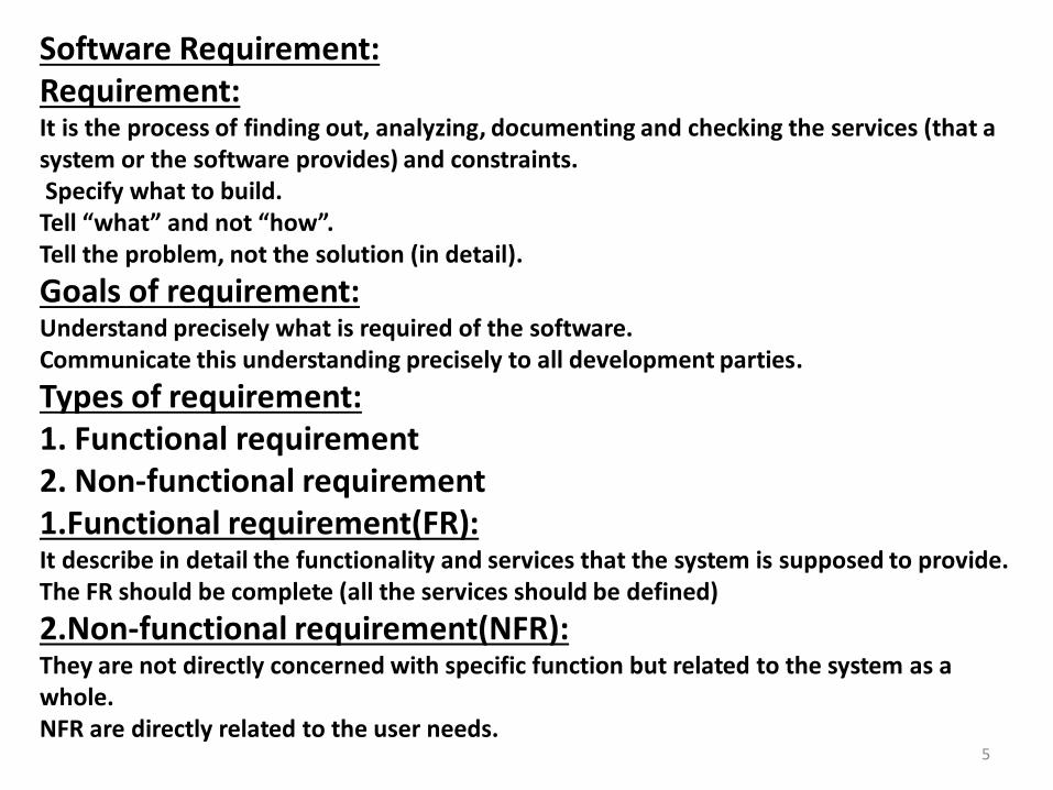
Software Requirement: Requirement: It is the process of finding out, analyzing, documenting and checking the services (that a system or the software provides) and constraints. Specify what to build. Tell “what” and not “how”. Tell the problem, not the solution (in detail).
Goals of requirement: Understand precisely what is required of the software. Communicate this understanding precisely to all development parties.
Types of requirement: 1. Functional requirement 2. Non-functional requirement 1.Functional requirement(FR): It describe in detail the functionality and services that the system is supposed to provide. The FR should be complete (all the services should be defined)
2.Non-functional requirement(NFR): They are not directly concerned with specific function but related to the system as a whole. NFR are directly related to the user needs. 5

Increment model: When to use? If it is too risky to develop the whole system at once, then the incremental development should be considered.
Increment model: It is the hybrid model means that combination of linear sequential and prototyping model. Basic idea behind this model is that it delivers software in small but usable pieces called increments. Each and every increment refines the software.
Example of incremental model: Word processing software is developed using the incremental model i.e: 1st increment: Text, New, Save, open, Close 2nd increment: cut, copy, paste, bold 3rd increment: Background, Spelling and grammar, Themes, images 4th increment: Charts, Shapes, Graphics 5th increment: Import, Export. And thus this process going on till the complete development.
6

Advantages of Incremental: Low risk of project failure. Customers become used to the system. Most essential gets more testing. In large project it is useful.
Disadvantages of incremental: The increment should be small. It is difficult to identify the facilities that all increments should require.
7

Prototyping Model: When the customers and the software developer both does not know about all the requirements, so, the customer just describe what type of the system he want only..
Types of prototyping model: Throw away prototyping Evolution prototyping
1. Throw away prototyping: This approach suggests that the constructed prototype should be discarded and the software should build
2.Evolution prototyping: it is an initial developing process for giving the users a working system and refining this by getting feedback from the end users until an adequate system has been developed.
Advantages of prototyping: Appropriate for small or medium size interactive system. This model is usefully in situations where the user requirements unclear or ambiguous. New version (better) is provided.
8

Disadvantages of prototyping: Suffer from bad documentation. Long-term maintenance is a problem. Project management difficulties.
9
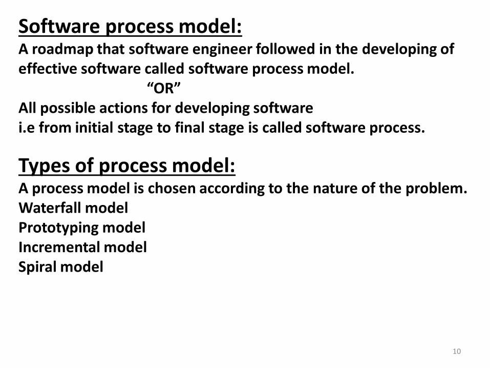
Software process model: A roadmap that software engineer followed in the developing of effective software called software process model. “OR” All possible actions for developing software i.e from initial stage to final stage is called software process.
Types of process model: A process model is chosen according to the nature of the problem. Waterfall model Prototyping model Incremental model Spiral model
10

Application of software: 1.system software: System software is a collection of program written to serve other program. e.g. compiler, operating systems, driver etc.
2. application software: Set of program written by experts for non-experts to accomplish certain task in a convenient way. Business software, database and educational software are some form of application software.
11

Software design Data Design: A repetitive process through which the requirement of the user are transformed to such a format that be used for a code generation.
Design principle: There are 10 principles. 1): The design should not suffer from the tunnel vision. 2): Design should be traceable to analysis model. 3): Design should not re-invent the wheel. 4): The minimum intellectual difference between the software is the real world problem. 5): There should be uniformity and integrity. 6): Design should accommodate change. 7): Design should be Structure to degrade gently. 8): The design should enhance the quality of the software. 9): The design should be review to minimize the conceptual errors. 10): Coding is not design and design is not coding.
12

Architectural Design: “The decomposition of the project into modules and to show the control relationship among the modules is called architectural design.” Architectural style: 1): Data Centered Architectures: A database resides at the center and is accessed frequently by other components that update, delete and modify data within the store. If there is any modification in the client, it will be visible to only that client.
2): Data Flow Architecture: It applies in situation where input is transformed to output by a number of computational components. The style is composed of two things. Pipes (b) Filter Pipes are simple connectors and the filters are processes that accept the input and generate the output after processing it. However, the filter does not require knowledge of the working of its neighboring filters. 13

3): Call and Return: This is most commonly used approach. It is having a calling module and receiving module. The receiving module accepts the input and returns the required response.
This method can be used by two ways. (a): Main program/Sub program (b) Remote Procedural call 4): layered Architecture: In this architecture, a number of different layers are defined, each accomplishing operations or supposed to perform a specific job. Outermost layer is the user interface layer then the inner layer is the application layer then intermediate layer provide utility services.
14

User Interface Rules: User interface design creates an effective communication medium between a human and a computer. The rules are grouped up into 3 categories: Place the user in control. Reduce the user memory load. Make the interface consistent
(a): Place the user in control: To give the impression to the user that he/she has the whole control of the software. To provide choices for flexible interactions. Define the interaction mode that does not force the user to do unnecessary actions. Allow the user interactions to be interruptible and undoable. Streamline interactions as skill level advance and allow the interaction to be customized. 15

(b): Reduce the user memory load: Interfaces should be designed in such a way that the user need not to memorize following are the design principle that enable an interface to reduce the user’s memory load. Establish meaningful defaults. To define shortcuts. Reduce demand in short term memory. Disclose information in a progressive fashion.
(c): Make the interface consistent: (i) All the visual information are organized according to a design standard that is maintained throughout all screen displays. (ii) If the users are familiar to some already build up standards then these may not be changed. E.g. if we are using Ctrl+C for copy, its standard then it must be used in the new software.
16

Component level design: It represents the software at a level that is close to code. It may be in the form of; 1). Graphical Design Notation. 2). Tabular Design Notation. 3). Text-based Program is composed of many functions. A program is composed by 4 basic constructs. a). Sequential b). Conditional c). Selection d). integrative
1): Graphical Design Notation: A): flow chart b): box diagram
a): flow chart: A flow chart is quite simple pictorially.
b): box diagram: A box is used to indicate a processing step.
17

2): Tabular Design Notation: In tabular we do not consider all the 4 constructs. Used in special situation. It can be applied on additional construct only.
3): Text-based: PDl: program Development language.
It is also called structured English, PDL and pseudo code.
PDL Rules: 1). There should be fixed syntax for all construct. 2). A list of key words should be defined. 3). Data declaration facility should be there. 4). Free syntax be describe the processing features.
18

ERD (Entity Relationship Diagram): ERD is a data model use for describing the structure of the data that system process, which specify in term of entity, attributes and their relationship. ERD shows the diagrammatic representation of data Modeling.
Steps for ERD: 1). Find out data objects and its attributes. 2). Define Relationship 3). Explore Cardinality and modality.
19

Functional Modeling: It is the 2nd activity of analysis modeling. This shows that how data flows inside the system. Diagrammatically it can be represented by DED
Symbols:
d):
c):
a):
b):
External Entity (ip/op)
Data flow
Data store
Internal Entity (Process)
20

DFD (Data Flow diagram): As we know that ERD describes objects and relationships between these objects and at that stage (ERD) we don,t know what system actually does? i.e how the system will be operated and how it accepts input to transforms output. So , all these are impossible to depict in ERD so for this purpose we use DFDs. For Funtional Modeling the technique which is used is called DFD. DFD show the flow of data throug a system. DFD show the movement of data.
Level in DFD: Level 0 Level 1 Level 2
Rules for DED: 1). The level ‘0’ DFD should represent the software as a single circle. 2). Define primary input and outputs. 3). Refine to the next level. 4). Label the arrows and circles. 5). Flow continuity must be maintain. 6). One circle should be refined at a time. 21
Behavioral Modeling: Behavioral Modeling model the overall behavior of system in graphical and textual form. The way in which the system responds or reacts to an event is called behavioral modeling. It concerns with the operational aspects of system. Diagrammatically it can be represented by STD (state transition Diagram). State is any observational mode of behavior. STD shows the states of the system and the transition among them caused by some events.
22
Data Dictionary: This is also called data repository. It contains data about data. It is simply a record of data about data. Although the format of data dictionary varies from tool to tool but most contain the following. Name e.g. student Ali student Where use / how use Content description notation i.e.= is composed + add,[1] either or Supplementary data types, initial value, restriction limitation
23

System Requirements: System requirement are more detailed description of the user requirements. It is the detail system requirement written by a team of developer for a client. It provides a base for system design and include the following design information. 1). The initial architecture of the system show be defined, including all the sub system. 2). It show the interaction of the system with other external systems that consumer or produce information.
24
Analysis Modeling: Definition: A combination of text and diagrams to represent the data, functions and behavior in a straight forward and understandable way that will be used for correctness, completeness and consistency.
Data Modeling: It defines all the data objects that are processed within the system, the relationships between the data objects and other supplementary information. Diagrammatically it can be represented by ERD.
Data Objects: Anything about which we have some composite information (hacking multiple characteristics). E.g. Student, Teacher etc...
Attributes: Properties of the data object that clarify its meaning. E.g. id, name, f/name etc.
25

Relationship: The association or connection among the data objects to have a bound among them. It is of two types. a). Cardinality b). Modality
Cardinality: The maximum number of occurrence of a entity with respect to another entity. The cardinality may be; One to One One to Many Many to Many
26

27
Prototyping Process Model:
Communication
Deployment Feedback
Constructional prototype
Quick plan/Quick Design
Advantages: 1). Users are actively involved in the development. 2). Errors can be detected much earlier. 3). Quick user feedback available leading to better solution. 4). By using the prototyping the user get the true working environment of the actual system to be designed & developed.
Disadvantage: 1). Time consuming & costly. 2). The developer has loses focus of the real purpose of prototypes & hence may compromise with the quality of the software. 3). Prototype can leads to false expectations.

28
Incremental Process Model:
Analysis Increment 1 Design Code Test Delivery of Increment 1
Increment 2
Increment n Analysis Design Code Test Delivery of Increment n
Advantage: 1). It can result in better testing, since testing each increment is likely to be easier then testing entire system. 2). Similar to prototype, each increment provide feedback which is useful for determing further/final requirement of system. 3). Customers get important functionality early.
Disadvantages: 1). Require good planning & design. 2). Require early definition of a complete & fully functional system to allow for the definition of increments. 3). Expensive.
29
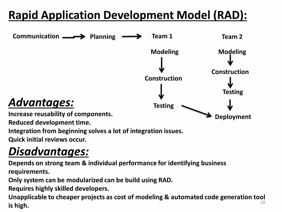
Rapid Application Development Model (RAD):
Communication Planning
Modeling
Construction
Testing
Team 1 Team 2
Modeling
Construction
Testing
Deployment
Advantages: Increase reusability of components. Reduced development time. Integration from beginning solves a lot of integration issues. Quick initial reviews occur.
Disadvantages: Depends on strong team & individual performance for identifying business requirements. Only system can be modularized can be build using RAD. Requires highly skilled developers. Unapplicable to cheaper projects as cost of modeling & automated code generation tool is high.

30
Steps of Requirement Engineering: 3.Elaboration: Where basic requirement are refined & modified. Present the functional & technical model. The end-result of elaboration is an analysis model that defines the informational, functional & behavioral domain of the problem.
Analysis Model:
e
xsxxxxddddxxErrrvsvsvvfffff Data dictionary
Behavioral Modeling
Process speciation Modeling
Data modeling

31
Use case:
1. Shows how the system is going to be used.
2. Help the user & developer.
3. Aid the tester.
4. Traceability. Book Search
Book Reserve
Book Return
Update catalog
Student
Liable