THIS MANUAL MUST BE LEFT WITH THE HOMEOWNER FOR …
8
Page 1 THIS MANUAL MUST BE LEFT WITH THE HOMEOWNER FOR FUTURE REFERENCE WARNING Improper installation, adjustment, alteration, service or maintenance can cause personal injury, loss of life, or damage to property. Installation and service must be performed by a licensed professional installer (or equivalent) or a service agency. Shipping and Packing List Check unit for shipping damage. Consult last carrier immediately if damage is found. Qty. Part Description 1 Digital ventilation controller (includes outdoor temperature sensor) 1 Motorized damper (spring-closed, power-open) 1 24VAC transformer Application Healthy Climate LVCS Ventilation Control System provides fresh air intake which can be used with any furnace or air handler. Fresh air is brought into the return air system, where it can be filtered. The controller allows fresh air intake using a motorized damper when outdoor conditions are appropriate. In very cold climates, balanced ventilation is recommended. Ventilation control system can be used with an exhaust fan to provide balanced ventilation. Per ASHRAE 62.2-2010, very cold climates are those that have more than 9000 annual heating degree-days based on 65°F day. Specification Operating temperature range 20 - 160°F Maximum current through VENT relay 2A Input voltage 22 - 30 VAC Minimum VA required 2.0 VA Ventilation time/hour 0-60 minutes Operation Principles Working in conjunction with a normally closed motorized damper, the digital ventilation controller makes decisions regarding when – and how long – to ventilate. It does this through continuous monitoring of indoor relative humidity, outdoor temperature, and user-adjusted timer settings. Ventilation time may be satisfied by a heating, cooling, or fan call initiated by the thermostat, or from a fan call initiated by the ventilation controller itself. Indoor relative humidity is monitored to help prevent high humidity conditions inside your home. If the indoor RH is above 55% and the outdoor temperature is above 50°F the damper will not open due to the potential of introducing excess humidity into the conditioned space unless mode A (time-based ventilating regardless of temperature or humidity) is selected on the controller. If the outdoor air temperature is • Below 0°F or above 100°F in modes B, and C. • Below 0°F or above 90°F in mode D. The normally closed motorized damper to the outside will not open. This function can be disabled by selecting mode A on the 4-way mode selector (see figure 8) where the outdoor air temperature and indoor humidity is not used as an input. CAUTION Improper wiring to the HVAC equipment could cause damage to the digital ventilation controller and/or the HVAC equipment. VENTILATORS 505,007M 08/2018 Supersedes 04/2016 LVCS VENTILATION CONTROL SYSTEM INSTALLATION, OPERATION AND MAINTENANCE INSTRUCTIONS FOR HEALTHY CLIMATE ® LENNOX VENTILATION CONTROL SYSTEM (LVCS) FOR USE WITH FURNACES AND AIR HANDLERS
Transcript of THIS MANUAL MUST BE LEFT WITH THE HOMEOWNER FOR …

Page 1
THIS MANUAL MUST BE LEFT WITH THE HOMEOWNER FOR FUTURE REFERENCE
WARNINGImproper installation, adjustment, alteration, service or maintenance can cause personal injury, loss of life, or damage to property.
Installation and service must be performed by a licensed professional installer (or equivalent) or a service agency.
Shipping and Packing List
Check unit for shipping damage. Consult last carrier immediately if damage is found.
Qty. Part Description1 Digital ventilation controller (includes outdoor temperature
sensor)
1 Motorized damper (spring-closed, power-open)
1 24VAC transformer
Application
Healthy Climate LVCS Ventilation Control System provides fresh air intake which can be used with any furnace or air handler. Fresh air is brought into the return air system, where it can be filtered. The controller allows fresh air intake using a motorized damper when outdoor conditions are appropriate. In very cold climates, balanced ventilation is recommended. Ventilation control system can be used with an exhaust fan to provide balanced ventilation. Per ASHRAE
62.2-2010, very cold climates are those that have more than 9000 annual heating degree-days based on 65°F day.
Specification
Operating temperature range 20 - 160°F
Maximum current through VENT relay 2A
Input voltage 22 - 30 VAC
Minimum VA required 2.0 VA
Ventilation time/hour 0-60 minutes
Operation Principles
Working in conjunction with a normally closed motorized damper, the digital ventilation controller makes decisions regarding when – and how long – to ventilate. It does this through continuous monitoring of indoor relative humidity, outdoor temperature, and user- adjusted timer settings. Ventilation time may be satisfied by a heating, cooling, or fan call initiated by the thermostat, or from a fan call initiated by the ventilation controller itself.
Indoor relative humidity is monitored to help prevent high humidity conditions inside your home.
If the indoor RH is above 55% and the outdoor temperature is above 50°F the damper will not open due to the potential of introducing excess humidity into the conditioned space unless mode A (time -based ventilating regardless of temperature or humidity) is selected on the controller.
If the outdoor air temperature is
• Below 0°F or above 100°F in modes B, and C.
• Below 0°F or above 90°F in mode D.
The normally closed motorized damper to the outside will not open. This function can be disabled by selecting mode A on the 4-way mode selector (see figure 8) where the outdoor air temperature and indoor humidity is not used as an input.
CAUTIONImproper wiring to the HVAC equipment could cause damage to the digital ventilation controller and/or the HVAC equipment.
VENTILATORS
505,007M08/2018Supersedes 04/2016
LVCS VENTILATION CONTROL SYSTEM
INSTALLATION, OPERATION AND MAINTENANCE INSTRUCTIONS FOR HEALTHY CLIMATE® LENNOX VENTILATION CONTROL SYSTEM (LVCS)
FOR USE WITH FURNACES AND AIR HANDLERS

Page 2
Figure 1. Typical Fresh Air Intake for Attic Installation
Figure 2. Typical Fresh Air Intake for Basement Installation
WARNINGElectric Shock Hazard. Can cause injury or death. Unit must be grounded in accordance with national and local codes.
Line voltage is present at all components when unit is not in operation on units with single-pole contactors. Disconnect all remote electric power supplies before opening access panel. Unit may have multiple power supplies.
Installation
LVCS requires installation of a motorized damper, fresh air intake (such as wall mounted hood), fresh air intake duct, digital ventilation controller, and 24VAC transformer.
Fresh air intake duct and damper should be installed between the outdoor wall and the return side of the HVAC equipment. The digital ventilation controller should be mounted in the return/mixing plenum and wired to the thermostat and the HVAC equipment.
INSTALLATION OF FRESH AIR INTAKENOTE - Fresh air intake should be located in accordance with local codes. Refer to installation guidelines as follows:
• At least 6 feet* away from dryer vents and furnace exhaust (high efficiency furnaces)
• A minimum of at least 6 feet* from sources of contaminated air (including driveways, oil fill pipes, gas meters, garbage containers or swimming pools)
• At least 18 inches* above the ground, or the depth of expected snow accumulation, whichever is higher
• At least 3 feet* from the inside/outside corner of the building
• Do not locate in any indoor space
• Provide 1/4" mesh screen or similar in the fresh air intake.
* Local code may require greater distances. Refer to figures 1 and 2 for typical attic and basement installations.
OUTSIDEWALL
FRES
H AIR
FRESH AIRINTAKE DUCT
MOTORIZEDDAMPER
VENTILATIONCONTROLLER
AIRFLOW
FURNACE/AIR HANDLERFILTER
FRESH AIRINTAKE HOOD
W/SCREEN
RETURN DUCT SUPPLYDUCT
HUMIDIFIER
6” minimum
VENTILATION CONTROLLERAIR FLOW(RETURN)
FILTER FURNACE/AIR HANDLER
FRESH AIRINTAKE HOOD
W/SCREEN
FRESH AIRINTAKE DUCT
MOTORIZEDDAMPER
FRES
H AIR
GABLE END WALL, BAND JOIST, OR PORCH SOFFIT
SUPPLYPLENUM
6” minimum
90-948
90-948

Page 3
Figure 3. Damper and Fresh Air Duct Installation
Figure 4. Digital Ventilation Controller
SUPPLY DUCT
ROUNDDAMPER
DO NOT INSULATE ACTUATOR
AIR FLOWDIRECTION
90-2117
INSTALLATION OF DAMPER AND FRESH AIR INTAKE DUCTNOTE - Support all ducts in accordance with local code or SMACNA standards.
CAUTIONDamper should be installed in fresh air duct only, and should be installed as close to the return duct as possible.
CAUTIONDo not force damper blades by hand, as damage may occur.
1. The motorized damper must be installed on a rigid return air duct or plenum. If flexible duct has been used rather than rigid duct for the return air, a field-provided return air mixing box must be installed. Position damper so that crimped end is downstream and attach damper to a return air duct, plenum, or mixing box.
2. Install 6 inch fresh air intake duct between the fresh air intake and damper. If metal fresh air duct is used, secure duct using 1/2 inch sheet metal screws (not included) and duct tape. If flexible fresh air duct is used, use proper strapping material to attach the duct to damper. Fresh air intake duct run should be as short as possible
3. The fresh air intake duct and damper must be fully insulated and all seams must be sealed to prevent condensation from forming. Refer to figure 3.
INSTALLATION OF DIGITAL VENTILATION CONTROLLER
CAUTION1. Do not mount the digital ventilation controller on the
supply plenum duct. The unit will not withstand the supply temperatures.
2. When installing the digital ventilation controller on down-flow furnaces, ensure blower continues to run after a heat call is satisfied to eliminate high temper-atures from damaging the digital ventilation control ler.
3. Do not mount the digital ventilation controller down-stream of a fresh air intake, humidifier or bypass out let. False humidity conditions will cause the digital ventilation controller to operate incorrectly
4. UVC light may damage ventilation control system components. Do not install ventilation control sys tem components where they may be exposed to UVC light.
The digital ventilation controller must be mounted in the return duct. For proper operation, the digital ventilation controller must be at least 6 inches upstream from the following:
• Fresh air intake duct connection
• Humidifier
• Humidifier bypass duct connection
In installations where it is difficult to mount the digital ventilation controller 6 inches upstream from the fresh air intake duct (when using a mixing box with flex duct returns for example), then mount the digital ventilation controller as close to the main return duct as possible.
Do not install the digital ventilation controller on the bottom side of duct. Also, do not install the digital ventilation controller within 6 feet of direct UVC light exposure or within 3 feet of indirect UVC light exposure.
NOTE - Make sure the digital ventilation controller sensor gasket is sealed tightly around the drilled hole. Do not install the digital ventilation controller without the gasket.

Page 4
1. Remove the knob.
2. Remove the cover by pulling at the bottom and swing out and up.
3. After the location of the digital ventilation controller is selected, drill a 3/4 inch hole for the RH sensor (the RH sensor extends from the back of the controller).
• Route wire from the R, C and W terminals on the digital ventilation controller to the corresponding terminals on the furnace / air handler/heat pump control. Do not remove any existing R, C, and W leads already connected. See figure 6 for the terminal locations.
NOTE - Due to the digital ventilation controller being wired to W and G, ventilation would initiate with a call just from the heat pump. In the case where the digital ventilation controller is setup with an outdoor temperature sensor and the temperature is below 20°F (mode B), ventilation would only be allowed when there is an electric heat call.
• Disconnect the thermostat wire from the HVAC terminal G and connect it to the digital ventilation control G terminal.
• Wire Gf on the digital ventilation control to the HVAC terminal G. The only wire connected to HVAC G will be from the ventilation control Gf terminal.
• Wire the 24VAC transformer (provided with the ventilation control system only). The transformer should be continuously energized, do not wire into the HVAC blower circuit. The transformer, damper and the digital ventilation controller VENT terminals will be wired in series.
MOTORIZED DAMPER AND 24VAC TRANSFORMERThe normally closed damper should be wired in series with a continuously energized 24VAC transformer (provided) and connected to the terminals labeled VENT of the digital ventilation controller. See figure 6.
The 24VAC transformer will require 110VAC power supply and should be installed according to the local codes. Wire 24VAC transformer to power source other than furnace fan motor circuit. The transformer can be powered off the 120VAC line at the junction box before it enters the furnace. See furnace manufacturer’s recommendations for wiring. 24VAC transformer is rated for use with one fresh air damper only and no additional components.
OUTDOOR TEMPERATURE SENSORThe temperature sensor should be installed in the fresh air intake hood (not provided) or in the fresh air intake duct.
NOTE - The outdoor temperature sensor should be within 3 feet of the outside wall when mounted inside the fresh air intake duct.
• Use standard 18-22 AWG thermostat wire to field wire outdoor temperature sensor to the digital ventilation controller.
• The outdoor temperature sensor is not affected by field wire length up to 300 feet between the sensor and controller. Do not route the wire alongside wires carrying high voltage (120VAC or greater) as interference may occur.
• Strip wire 1/4 inch, and insert the field wires from the sensor into the terminals labeled ODT on the digital ventilation controller. See Figure 6 for terminal locations.
• Do not mount in direct sunlight or below the expected snow line on exterior wall.
4. Before removing the adhesive backing, use the controller to mark the mounting holes and place anchors if applicable.
5. Clean the mounting surface of the duct, remove the adhesive backing from the gasket on the digital ventilation controller, and secure the digital ventilation controller to the duct making sure to align mounting holes and the RH sensor with the drilled hole.
• Mounting to Metal Duct: use field-provided sheet metal screws to secure controller to duct.
• Mounting to Duct Board: Use field-provided screws and anchors to secure controller to duct.
NOTE - Digital Ventilation Controller Replacement - When replacing an X4153 with an Y5862, the duct opening left by the removed digital ventilation controller must be covered completely. Locate and install the new controller as instructed above.
Field Wiring
DIGITAL VENTILATION CONTROLLERNOTE - 18-22 AWG thermostat wire should be used.
CAUTIONImproper wiring to the HVAC equipment could cause damage to the digital ventilation controller and/or the HVAC equipment.
Figure 5. Mounting Digital Ventilation Controller (Metal Duct)
3/4" DIAMETER HOLE
90-1830

Page 5
Figure 6. Wiring the Digital Ventilation Controller (Conventional 24VAC Thermostat Used)
Figure 7. Wiring the Digital Ventilation Controller (Lennox Communicating Thermostats and Indoor Units)
CONTINUOUSLY POWERED24 VAC TRANSFORMERTHERMOSTAT
OUTPUTSINPUTSPOWER
GWCR VENTODT Gf
120 VAC
FURNACE
NOTUSED
Y5862 DIGITAL VENTILATION CONTROLLER TERMINAL STRIP
DAMPER
R
C
W
Y
GG
Y
W
C
R
iComfort WI-FI OR S30 SMART HUB CONNECTIONS
Y5862 LVCS DIGITAL VENTILATION CONTROL
120V COILRELAY
24VAC LVCSDAMPER TRANSFORMER
LENNOX COMMUNICATING INDOOR UNIT
56L68
POWER INPUTS OUTPUTS
OUTDOORTEMP. SENSOR
VENTILATIONDAMPER
NEUTRAL
OUTDOOR INDOOR
EAC/ACC120V
HVAC HEAT OR COOL CALL, OR THE FAN IS IN CONTINUOUS OPERATION, THE VENTILATION CONTROLLER WILL OPEN OUTDOOR AIR DAMPER TO VENTILATE IF THE OUTDOOR TEMPERATURE AND INDOOR HUMIDITY ARE WITHIN THE LIMITS OF THE VENTILATION CONTROLLER.
LVCS SET CYCLE TIME TO 1 HOURSET VENTILATION TIME TO 60 MINUTES
NOTE: USE THE iComfort CIRCULATE FAN PERCENTAGE OF ON* TIME TO CONTROL VENTILATION TIME
90-1829

Page 6
* If the indoor RH is above 55% and the outdoor temperature is above 50°F the damper will not open because of the potential of introducing excess humidity into the conditioned space.
ROTARY DIP SWITCH
Position Description ChartA
(Time Only)Timer controlled ventilation (no temperature or humidity limits).
This setting can be calculated with ASHRAE 62.2-2010 standard. (Temperature and humidity sensors are ignored.)
B (Default)
Timer controlled ventilation with humidity and temperature limits.
VENTILATION PREVENTED*VENTILATION ALLOWED
VENTILATION ALLOWED WITH HEAT
100°
20°
0°
55%INDOOR RELATIVE HUMIDITY
OU
TDO
OR
TEM
PERA
TURE
(F)
50°
VENTILATION PREVENTED
15% 25% 35% 45% 65%
C (Cold
Climate)
Timer controlled ventilation with humidity and temperature limits.
VENTILATION PREVENTED*
VENTILATION ALLOWED
100°
0°
55%INDOOR RELATIVE HUMIDITY
OU
TDO
OR
TEM
PERA
TURE
(F)
50°
VENTILATION PREVENTED
15% 25% 35% 45% 65%
D (Warm
Climate)
Timer controlled ventilation with humidity and temperature limits.
VENTILATION PREVENTED*VENTILATION ALLOWED
VENTILATION ALLOWED WITH HEAT
0°
55%INDOOR RELATIVE HUMIDITY
OU
TDO
OR
TEM
PERA
TURE
(F)
50°40°
VENTILATION PREVENTED
15% 25% 35% 45% 65%
90°
Figure 8. Operating Modes
Mode Selection
This digital ventilation controller is equipped with rotary DIP switch (see figure 8).
• The A mode allows the controller to ventilate based on time only.
• The B, C and D modes allow the digital ventilation controller to ventilate based upon time, outdoor temperature and indoor humidity.
Page 7
Figure 9
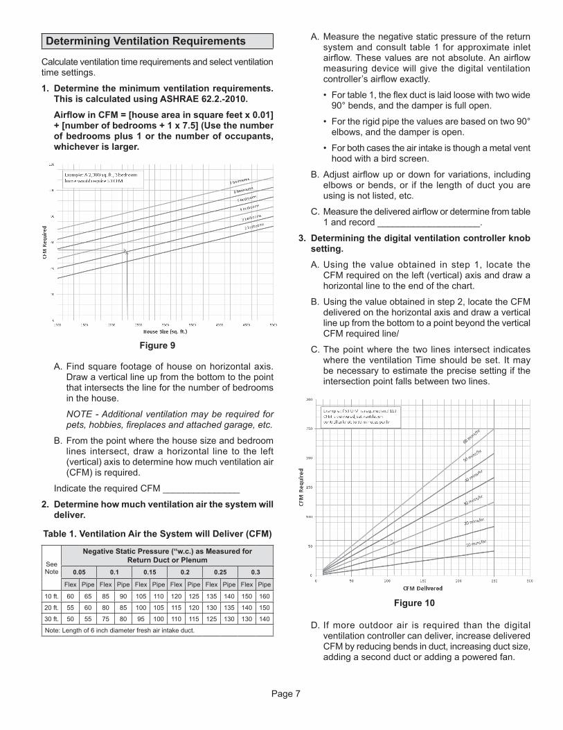
Figure 10
Determining Ventilation Requirements
Calculate ventilation time requirements and select ventilation time settings.
1. Determine the minimum ventilation requirements. This is calculated using ASHRAE 62.2.-2010.
AirflowinCFM=[houseareainsquarefeetx0.01]+[numberofbedrooms+1x7.5](Usethenumberofbedroomsplus1orthenumberofoccupants,whicheverislarger.
D. If more outdoor air is required than the digital ventilation controller can deliver, increase delivered CFM by reducing bends in duct, increasing duct size, adding a second duct or adding a powered fan.
A. Measure the negative static pressure of the return system and consult table 1 for approximate inlet airflow. These values are not absolute. An airflow measuring device will give the digital ventilation controller’s airflow exactly.
• For table 1, the flex duct is laid loose with two wide 90° bends, and the damper is full open.
• For the rigid pipe the values are based on two 90° elbows, and the damper is open.
• For both cases the air intake is though a metal vent hood with a bird screen.
B. Adjust airflow up or down for variations, including elbows or bends, or if the length of duct you are using is not listed, etc.
C. Measure the delivered airflow or determine from table 1 and record ____________________.
3. Determiningthedigitalventilationcontrollerknobsetting.
A. Using the value obtained in step 1, locate the CFM required on the left (vertical) axis and draw a horizontal line to the end of the chart.
B. Using the value obtained in step 2, locate the CFM delivered on the horizontal axis and draw a vertical line up from the bottom to a point beyond the vertical CFM required line/
C. The point where the two lines intersect indicates where the ventilation Time should be set. It may be necessary to estimate the precise setting if the intersection point falls between two lines.
A. Find square footage of house on horizontal axis. Draw a vertical line up from the bottom to the point that intersects the line for the number of bedrooms in the house.
NOTE - Additional ventilation may be required for pets, hobbies, fireplaces and attached garage, etc.
B. From the point where the house size and bedroom lines intersect, draw a horizontal line to the left (vertical) axis to determine how much ventilation air (CFM) is required.
Indicate the required CFM _______________
2. Determinehowmuchventilationairthesystemwilldeliver.
Table1.VentilationAirtheSystemwillDeliver(CFM)
See Note
NegativeStaticPressure(“w.c.)asMeasuredfor Return Duct or Plenum
0.05 0.1 0.15 0.2 0.25 0.3
Flex Pipe Flex Pipe Flex Pipe Flex Pipe Flex Pipe Flex Pipe
10 ft. 60 65 85 90 105 110 120 125 135 140 150 160
20 ft. 55 60 80 85 100 105 115 120 130 135 140 150
30 ft. 50 55 75 80 95 100 110 115 125 130 130 140
Note: Length of 6 inch diameter fresh air intake duct.

Page 8
System Checkout
Troubleshooting
Table2.TroubleshootingSymptom TroubleshootingProcedureHVACblowerdoesnotturn on in Test Mode.
1. Make sure HVAC equipment has power.2. Check the wiring for R, C, W, G and Gf at both the HVAC equipment and the digital ventilation controller.3. Check voltage across the digital ventilation controller R & C and C & Gf terminals. Voltage should be in the 22 to
30VAC range.
Damper does not open in Test Mode.
1. Make sure HVAC equipment has power2. Check the wiring for R, C, W, G and Gf at both the HVAC equipment and the digital ventilation controller.3. Check voltage across the digital ventilation controller R & C and C & Gf terminals. Voltage should be in the 22 to
30VAC range.4. Check wiring diagram to make sure the damper is wired in series with the circuit board and transformer.
The damper does not openwiththebloweroperating.
1. The damper will not operate once the ventilation time interval has been met. For example, if the knob is turned to 5 minutes and 5 minutes has elapsed, the damper will close and it will stay closed until the next 1-hour interval.
FOR ALL MODES EXCEPT MODE A2. If the indoor RH is above 55% and the outdoor temperature is above 50°F the damper will not open because of the
potential of introducing excess humidity into the conditioned space.3. If the outdoor temperature is below 0°F or above 100°F the damper stays closed.4. Verify that the outdoor temperature sensor is installed properly.5. Turbulence in the return duct, plenum or mixing box can give false readings. Confirm proper location.6. In Mode B, a heat call is required for ventilation under 20°F.7. In Mode D, a heat call is required for ventilation under 40°F.
Blowerturnsonunexpectedly.
If ventilation time has not been met, the controller will activate the blower. This is normal operation.
Table3.ErrorCodesError Code TroubleshootingProcedureE1 - RH Sensor Rotate knob to the TEST/RESET position. After 5 seconds, the green indicator will blink, resetting the error.
If E1 returns, replace the controller.
E2 - Controller Knob Rotate knob to the TEST/RESET position. After 5 seconds, the green indicator will blink, resetting the error. If E2 returns, replace the controller.
E3 - Outdoor Temperature Sensor
1. Make sure that the outdoor temperature sensor (ODT) is properly connected to the ODT terminals on the controller.
2. Measure the resistance of the ODT sensor by removing the wires from the terminals and measuring the resistance across the wires with an ohmmeter. Confirm the reading with the temperature in the table. If the resistance value does not match the temperature value, replace the ODT sensor.
3. Reset error by rotating knob to TEST/RESET then back to the normal settings.
NOTE - ODT must be installed for modes B, C and D.
Outdoor Temperature (°F)
Resistance (k ) ±10
-30 231.8-20 163.4-10 117.30 84.8
10 62.220 46.130 34.440 26.150 19.960 15.370 11.980 9.390 7.3100 5.8
Turn the time setting knob to the TEST/RESET position. If the installation is correct the HVAC blower will turn on (independent of heat or cooling operations) and the damper will open for 1 minute unless the knob is turned off of TEST/RESET. If the system does not operate, then see the troubleshooting section.
Return the time setting knob to the calculated setting. Donot leave inTEST/RESET,thedigitalventilationcontrollerwillnotoperate.
Repair Part LennoxCatalogNumberDigital ventilation controller Y5862
Motorized damper (spring-closed, power-open) X4152
24VAC transformer 22N03
Outdoor temperature sensor 58N66
10011432 8.18B2206797C