West Sound Consortium Options - West Sound Consortium Options 2015

This Manual has been created as part of the consortium objectives within the:
Integrated WASH and Protection Response to DRC and South Sudan refugee influx
(in) South Western and West Nile regions of Uganda.
In partnership with the European Union Civil Protection and Humanitarian Aid (ECHO),
OXFAM; and Engineers Without Borders USA.
This publication was produced with the financial support of the European Union. Its contents are the sole
responsibility of Engineers Without Borders and do not necessarily reflect the views of the European Union.
2 SPWS Operation and Maintenance Manual
Table of Contents
Abbreviations ...................................................................... Error! Bookmark not defined.
Definitions ...................................................................................................................... 6
Normative References .................................................................................................... 8
Background and Structure of this Manual ....................................................................... 9
GENERAL O&M MANAGEMENT AND SAFETY CONSIDERATIONS ....................................... 10
1. General Introduction to Solar Powered Water Systems ......................................... 11 Appropriate Applications ...................................................................................................................... 11 Advantages and Disadvantages of Solar Powered Water System ........................................................ 12 Difference between Solar Powered and Conventional (grid/diesel generator powered) Water
Pumping ....................................................................................................................................................... 13 Components of Solar Powered Water Systems .................................................................................... 14
1.4.1. The Solar Module Array ................................................................................................................. 17 1.4.2. How Shade affects the Solar Array ................................................................................................ 19 Definitions and Terminology ................................................................................................................. 19
1.5.1. Operation vs. Maintenance vs. Diagnostics / Testing .................................................................... 19
2. Management, Roles and Responsibilities ............................................................... 21 Tasks and Responsibilities of the Scheme Operator (SO) ..................................................................... 21 Tasks and Responsibilities of the System Technician (ST) .................................................................... 22 Record-Keeping ..................................................................................................................................... 23
3. Safety for Solar Powered Water System Operations & Maintenance ..................... 24 Personal Protective Equipment (PPE) ................................................................................................... 24 Electrical Hazards .................................................................................................................................. 25
3.2.1. Types of Electrical Hazards ............................................................................................................ 26 3.2.2. Solar Panels ................................................................................................................................... 27
3.2.2.1. General Recommendations for Safety when working on Solar Panels .................................. 27 3.2.2.2. Do Not Open MC-4 Connectors .............................................................................................. 28
3.2.3. Grounding and Bonding ................................................................................................................. 29 3.2.4. Lightning Storms ............................................................................................................................ 30 3.2.5. Pump House / Pump Enclosure ..................................................................................................... 31 3.2.6. Submersible Pump Motor and Pump ............................................................................................ 31 3.2.7. Pump Motor Controller ................................................................................................................. 32 3.2.8. Wire Insulation .............................................................................................................................. 32 3.2.9. Skilled Technician Requirements ................................................................................................... 32 3.2.10. Testing and Diagnostics Safety .................................................................................................... 32 3.2.11. Summary of Major Electrical Safety Rules ................................................................................... 33 Chemical Hazards .................................................................................................................................. 33 Fire Hazard ............................................................................................................................................ 34 Equipment Safety and Care .................................................................................................................. 35
3.5.1. Well ................................................................................................................................................ 35 3.5.2. Pressure Line from Well to Storage Tank ...................................................................................... 36 3.5.3. Storage Tank .................................................................................................................................. 36

3 SPWS Operation and Maintenance Manual
3.5.3.1. Ladder Safety.......................................................................................................................... 36 3.5.4. Distribution System ....................................................................................................................... 37 Personal Safety ..................................................................................................................................... 37
4. Routine Operation and Preventative Maintenance ................................................ 39 General Guidance ................................................................................................................................. 39 Routine / Daily Operation ..................................................................................................................... 40
4.2.1. Daily Water Production Record ..................................................................................................... 40 4.2.2. Capturing Water Production Data ................................................................................................. 42
4.2.2.1. How to use a Piezometer ....................................................................................................... 42 4.2.2.2. How to read the Water Meter ............................................................................................... 43
4.2.3. Daily Record/Checklist ................................................................................................................... 43 4.2.3.1. Solar Panel Care ..................................................................................................................... 44 4.2.3.2. Pump ...................................................................................................................................... 44 4.2.3.3. Pump Controller (Inverter) ..................................................................................................... 45 4.2.3.4. Daily Pump and Pump House Activities ................................................................................. 45
Regular (Weekly) Operations and Preventative Care ........................................................................... 46 4.3.1. ROUTINE (WEEKLY) ACTIVITY SHEET ............................................................................................. 47 4.3.2. Solar Panels ................................................................................................................................... 49 4.3.3. Lightening Arrestor and Grounding ............................................................................................... 49 4.3.4. Well head ....................................................................................................................................... 49 4.3.5. Submersible Pump and Motor ....................................................................................................... 50 4.3.6. Pump Controller / Inverter ............................................................................................................ 50 4.3.7. Pump House / Pump Enclosure ..................................................................................................... 50 4.3.8. Pressure Line from Well to Storage Tank ...................................................................................... 50 4.3.9. Chlorine Dosser ............................................................................................................................. 51 4.3.10. Storage Tank ................................................................................................................................ 52 4.3.11. Distribution System ..................................................................................................................... 52 4.3.12. Taps and Tap Stands .................................................................................................................... 53
5. Trouble-Shooting and Minor Repair ....................................................................... 54

4 SPWS Operation and Maintenance Manual
Foreword
Engineers Without Borders – USA is a non-profit humanitarian organization established to
partner with developing communities worldwide in order to improve their quality of life. In
Uganda we have among others partnered with the Ministry of Water and Environment and
several other non-governmental organizations including Oxfam.
As a partner implementing the ECHO–HIP funded “Integrated WASH and Protection
Response to DRC and South Sudan refugee influx in South Western and West Nile regions of
Uganda” program with Oxfam-Uganda, one of the key deliverables for Engineers Without
Borders (EWB) - USA is capacity development in the management, operation and maintenance
of water systems in refugee settlements and host communities with a focus on transitioning to
sustainable operation and technical capacity of institutional operators.
This manual is primarily designed as a practical guide for field engineers evaluating, designing
and installing solar powered gravity-fed water systems (SPWS). The body of the document
contains general instructions, design, installation and operation and maintenance guidance. The
appendices at the end of the document are a series of field instruments intended to be printed
out and carried in the field to aid design and installation.
The authors and contributors that formed the team led by Engineers Without Borders – USA
include: Philip Powell, Louis Woofenden, Mac Prather, Eric Lundborg, Larry Bentley, and
Francis Okello.
I further would like to acknowledge the support of OXFAM Kenya, the GLOWSI project,
Water Missions, IOM, and all those who provided valuable information and support towards
this effort.
Zoe Pacciani
Country Director

5 SPWS Operation and Maintenance Manual
Abbreviations
AC Alternating Current
DC Direct Current
ECHO European Civil Protection for Humanitarian Aid Operations
EMC Electromagnetic compatibility
EWB - USA Engineers Without Borders USA
Ia Current (DC or AC) in ampere (from any source)
IEC International Electrochemical Commission
Im Motor current
Impp Solar PV panel maximum power point current in ampere
Irms Motor current (root mean square) effective value of AC
waveform
KVA Kilo-volt-ampere
KW Kilowatts
LCD Liquid Crystal Display
LED Light Emitting Diode
M3/h Flow rate
MWE Ministry of Water and Environment
NGO Non-Governmental Organization
O&M Operation and Maintenance
PSi Pounds per square inch
PV Photovoltaic
SO Scheme operator
SPWS Solar Powered Water System
ST System Technician
TDH Total Dynamic Head
TDS Total Dissolved Solids
UNBS Uganda National Bureau of Standards
Va Generator voltage DC (Volt)
Vm Motor voltage
Vmpp Solar PV panel maximum power point voltage DC (V)
VoC Solar PV panel open circuit voltage DC (V)
Vrms Motor voltage (root mean square) effective value of AC
waveform
WASH Water and Sanitation Hygiene

6 SPWS Operation and Maintenance Manual
Definitions
Array Any number of photovoltaic modules connected together to
provide a single electrical output. Arrays are often designed to
produce significant amounts of electricity.
Barres The force required to push water through the pipes. Also known
as PSi.
Grounding Grounding is accomplished by connecting neutral conductors to
the electrical grounding system, which is connected to the earth
by means of one or more grounding electrodes, typically ground
rods, plates or rings, buried metal water pipe, well casings or
structural building steel in contact with the earth. From Glossary
of Solar Pumping and Electricity
Electrical Bonding Electrical bonding is the practice of intentionally electrically
connecting all exposed metallic items not designed to carry
electricity in a room or building as protection from electric
shock. From Glossary of Solar Pumping and Electricity
Hertz
Incident Irradiance The irradiance on a surface, either tilted or flat, which will vary
depending on the tilt angle of the surface.
Inverter A device that converts direct current (DC) electricity into
alternating current (AC) electricity (single-phase or three-phase).
The device can also be referred to as a PV Converter.
Irradiation The sum of the incident irradiances at a given location on earth
over the course of a solar day (given in units of kWh/m2/day).
Maximum Power
Point (MPP)
The point on the current-voltage (I-V) curve of a module under
illumination, where the product of current and voltage is
maximum. [UL 1703] For a typical silicon cell panel, this is
about 17 volts for a 36-cell configuration.
Maximum Power Point
Tracker (MPPT)
A power conditioning unit that automatically operates the PV-
generator at its maximum power point under all conditions. An
MPPT will typically increase power delivered to the system by
10% to 40%, depending on climate conditions and battery state
of charge. You usually get more gain in winter and in colder
weather due to the higher panel output. Most MPPT controllers
are down converters - from a higher voltage to a lower one
Photovoltaic (PV) System PV systems convert irradiance (solar power) from the sun into
electricity.
PSi The force required to push water through the pipes. Also known
as Barres.
Sine Wave Inverter An inverter that produces utility-quality, sine wave power forms
Solar Array (or PV Array) A configuration of solar panels arranged and wired together to
output power as a single unit.
Solar Array Racking System Structural system designed and constructed to support the solar
array per the design conditions.

7 SPWS Operation and Maintenance Manual
Solar Irradiance The power per unit area received by the sun (the sun emits an
average of 1,367 Joules per second per square meter of surface
area, and of this, a maximum of approximately 1,000 Watts per
meter squared (W/m2) reaches the earth’s surface).
Solar Panels/Solar Modules Solar panels use sunlight (or light energy from the sun) to
produce electricity. Solar panels can also be referred to as
photovoltaic modules or generators (or PV modules or
generators) or a combination of those terms (such as solar PV
panels or photovoltaic solar panels). Solar PANEL and Solar
MODULE are used interchangeably throughout the document.
Solar Pump This term typically refers to pumps that have a controller
integrated into the pump and motor. It should be recognized that
these pumps can take any type of DC power input and not solar
exclusively.
Stand-Alone (PV system) An autonomous or hybrid photovoltaic system not connected to
a grid. May or may not have storage, but most stand-alone
systems require batteries or some other form of storage
Standard Test Conditions
(STC)
Conditions under which a module is typically tested in a
laboratory: (1) Irradiance intensity of 1000 W/square meter
(0.645 watts per square inch), AM1.5 solar reference spectrum,
and (3) a cell (module) temperature of 25 degrees C, plus or
minus 2 degrees C (77 degrees F, plus or minus 3.6 degrees F).
[IEC 1215]
STC Standard Test Conditions, defined as a cell temperature of 25°C,
an irradiance of 1,000 W/m2, and an air mass coefficient of 1.5
(AM1.5) (reference IEC 61215).
TDH Total Dynamic Head is the total elevation lift (including friction
loss) required of the pump in the water supply system.
Volt (V) A unit of measure of the force, or 'push,' given the electrons in
an electric circuit. One volt produces one ampere of current
when acting a resistance of one ohm.

8 SPWS Operation and Maintenance Manual
Normative References IEC Standards refers to the International Electrotechnical Commission Standards, to which
Uganda adheres. These standards provide the minimum guidance necessary ensure the safety
and quality of a product or procedure.
IEC 60364-1 Low-voltage electrical installations –
Part 1: Fundamental principles, assessment of general characteristics, definitions
IEC 61936-1 Power installations exceeding 1 kV AC – Part 1: Common rules
IEC TS 62257-5 Recommendations for renewable energy and hybrid systems for rural
electrification –
Part 5: Protection against electrical hazards
IEC 62548 Photovoltaic (PV) arrays – Design requirements
IEC 62253 Photovoltaic pumping systems – Design qualification and performance
measurements
IEC 60038 IEC standard voltages

9 SPWS Operation and Maintenance Manual
Background and Structure of this Manual One of the key challenges that the water sector grapples with is the poor operation and
maintenance of especially solar powered water systems. The solar powered water system is a
relatively recent technology of which uptake is on the rise mainly because of its low O&M
requirements. The systems are operated and maintained by scheme operators and technicians
with varying levels of qualification. Part of the reason why there is currently poor operation
and maintenance of solar powered water systems is the lack of a manual and training to guide
the scheme operators and technicians. This manual is therefore intended to for Scheme
Operators (SO) and Technicians (ST) as a guide on the operation and maintenance of solar
powered water systems.
The manual is divided into three major sections:
The Introduction to Solar Powered Water System and Important Safety Considerations
section gives a general introduction to solar pumping stations and discusses safety measures
needed to protect maintenance personnel and system users from site electrical, mechanical and
hydraulic hazards.
The Scheme Operator section targets the scheme operators in charge of routine operation and
basic preventive maintenance. It details when and how to complete typical monitoring tasks. It
also provides basic assessment procedures to determine if certified System Technicians or other
professional electricians need to be contacted to complete more complicated system repairs.
The System Technician section describes advanced repair activities to be carried out by
System Technicians (ST), who should possess a technical certificate/diploma in Engineering
from a recognized technical institute and have at least two years of practical experience in the
water supply sector, preferably in the design, installation or maintenance of water supply. The
section includes a list of common problems that arise in solar pumping systems which require
technical expertise. A list of possible causes is also provided to assist System Technicians (ST)
in identifying the source of the problem. Level 2 repairs require a professional electrician or
plumber and generally should not be attempted without this skilled supervision. Level 2
electrical procedures often require advanced diagnostics or work with energized equipment.
Level 2 hydraulic procedures often require having to shut down the hydraulic system to
perform a repair a pipe or operating component of the system.
Adhering to this manual will provide quality support and safety for the Solar Powered Water
System and personnel while minimizing operation and maintenance costs.

10 SPWS Operation and Maintenance Manual
GENERAL O&M MANAGEMENT AND SAFETY CONSIDERATIONS

11 SPWS Operation and Maintenance Manual
1. General Introduction to Solar Powered Water Systems It is common knowledge today that the prime source of energy supporting all forms of life is
the sun. The energy obtainable from fuel wood, fossil fuels and hydropower for example can
be traced to the sun. The virtually inexhaustible solar energy apparently far exceeds the global
energy needs (AEPC, 2003). With the ever-increasing concern about the environmental impact
of some sources of energy including petroleum, gas and coal, harnessing solar energy becomes
a default and logical alternative. The solar photovoltaic (PV) pumping system is one of the
applications for photovoltaics and can be classified based on the end-use application of the
technology.
A solar powered water system is like any other pumping system, except its power source is
solar energy. Solar pumping technology covers the entire energy conversion process, from
sunlight, to electrical energy, to mechanical energy, to stored energy. The solar irradiation is
captured by the solar electric panels, which then converts the sunlight into electricity. Through
a control box, whose major function is to condition the electricity from the panels, the pump
motor is powered and this drives the pump to pump the water into the reservoir. Water from
the reservoir is then supplied to the user. Figure 1 illustrates major components and the basic
functional principle of a solar powered water system.
Figure 1. Illustration of a Typical Solar Water Pumping System (Source: World Bank)
Appropriate Applications Solar powered water systems have been used in various contexts in Uganda with increasing
frequency. Solar energy, as a power source, has become a popular solution, particularly in rural

12 SPWS Operation and Maintenance Manual
areas where the national grid does not reach. Solar powered water systems are also being
installed in refugee settlements due to the relatively low operation and maintenance costs as
discussed below.
There are a number of suitable applications for solar powered water systems. These include:
• Potable water supply for institutions;
• Community scale water supply schemes for gravity-fed and stand-alone solar powered
water systems;
• Large scale water supply schemes using a solar-hybrid power combination to cover the
full scope of the demand;
• Livestock water supply;
• Small scale irrigation.
Advantages and Disadvantages of Solar Powered Water System
Solar powered water system has both advantages and disadvantages. Some of the advantages
include:
• Low costs: Consumes no fuel because it utilizes freely available sunlight as power
source. This significantly reduces operation and maintenance costs.
• Zero pollution: Unlike diesel-based systems (i.e. where a diesel generator powers the
pump), solar pumping produces clean energy with zero exhaust gases, noise or other
pollutants. Using solar instead of diesel-powered systems reduces carbon emissions by
2.6 kg per litre of diesel used. This accumulates to up to several tons per year.
• Durable: Solar pumping systems are durable and reliable. PV panels have a design life
of over 20 years, and solar pumps have few moving parts and require little maintenance
resulting in an increased overall sustainability of the system.
• Flexible: Solar pumping systems are modular so can be tailored to current power needs
and easily expanded by adding PV panels and accessories. Solar pumping systems can
be phased to reduce initial capital cost; a smaller system can initially be installed and
as demand increased the system can be easily scaled up.
• Safe: Properly installed solar systems are safe and low risk due to low system voltage.
Adequate protection minimizes fire risk.
• Autonomous: Stand-alone solar systems can be installed in remote locations,
eliminating expensive extensions of grid power.
• Future-oriented: Ongoing research and development in solar technology not only
points to increased global awareness and preference for solar water pumping
technology, but also results in higher efficiency and lower cost.
Some of the disadvantages of solar powered water systems and appropriate mitigation
measures include:
Table 1: Disadvantages of Solar Powered Water Systems and their Mitigation Measures Disadvantages Mitigation Measures

13 SPWS Operation and Maintenance Manual
High initial investment (capital) costs. The relatively high investment cost is gradually
coming down, thanks to research and innovation.
In addition, the payback is quick due to low
operation and maintenance costs, sometimes in
as little as 2 years.1
Increased water storage requirements sometimes
2 to 3 times the daily water demand due to
limited pump time based on sun-hours2.
To reduce the storage capacity to 30 – 50% of the
maximum daily demand, install a hybrid
solar/diesel pumping system so that water can
still be pumped when solar energy is not
available.
Specialized technicians in solar pumping may
be difficult to access in some areas.
Focused investment in the capacity development
of operators and technicians is required.
Panel theft. Sensitise communities and provide simple
antitheft measures.
Difference between Solar Powered and Conventional (grid/diesel generator powered) Water Pumping
While it may seem obvious that the main difference between solar and conventional (grid or
diesel) powered water pumping is the power source, this actually affects the flow of water over
the course of a day. Conventional power sources, or grid and fuelled generator have the
potential to power a water pump for 24 hours per day at a constant rate. Solar power, on the
other hand, drives a pump during sun-hours only and this rate slowly increases as the sun’s
intensity increases, and decreases at the end of the day as the sun’s intensity decreases.
The illustrations below explain how solar water pumping differs from other modes of pumping.
1 ECHO report, February, 2018 2 Sun-Hours refers to the number of hours the sun will shine directly on the solar modules to produce power.
While the sun may start to shine early in the morning the angle of the sun does not reach the panels until later in
the day. Sun hours for solar water pumping are most commonly calculated as

14 SPWS Operation and Maintenance Manual
Figure 2. Typical Flow Rate Curve with Grid Powered Fixed Speed Pump
Typically, when a fixed speed motor running an ordinary pump is powered from grid, a fixed
flow rate is expected over multiple hours as illustrated above.
Figure 3. Typical Flow Rate Curve with Solar Powered Pump
Conversely, under solar powered water systems, variable speed pumps are normally used and
as such, the flow rate will vary over time as shown in the curve above. The blue area represents
a constant flow rate for 8 hours while the red area represents an exemplary solar powered
pumping profile that corresponds to a typical solar irradiance profile.
Solar irradiance (the power per unit area - W/m2, received from the sun) is relatively little in
the morning and increases gradually over time until it peaks around midday hours. It then
decreases gradually until it disappears at sunset.
Components of Solar Powered Water Systems The main difference between solar powered water system and pumping with grid or generator
power is the source of energy. Solar powered water systems usually comprise of the following
components as shown in Figure 1 above and Figure 2 below:

15 SPWS Operation and Maintenance Manual
Figure 4. Illustration of a Typical Solar Water Pumping System Components
Components unique to solar powered water systems:
• Solar module array
• Lightening Arrestor
• Grounding Rods
• Combiner Box
• Inverter/Controller
Common components:
• Motorized Water Pump
• Transmission line (from the pump to the storage tank)
• Valves
• Chlorine Doser
• Storage tank or reservoir
• Distribution lines
The system can be separated into a Solar Pumping system which includes the power source,
the pump and motor, the well, and the high- pressure line to the storage tank and the distribution
system which carries the water from the tank to the tap stands/distribution points. The figure
below is an example of the components of the Solar Pumping System with the component
locations. The following figure shows the components of the gravity distribution system.
These two systems are joined at the water storage tank but operate independently and are
maintained with different types of skills. The operator or L1 technician monitors the entire
two system and implements repairs completely on the distribution system (may need plumbing

16 SPWS Operation and Maintenance Manual
support). The L2 technician primarily focuses on diagnosis on the pumping supply system for
annual monitoring and as requested diagnosis and repair.
Figure 5. Solar Pumping System Components
Figure 6. Gravity Distribution System

17 SPWS Operation and Maintenance Manual
1.4.1. The Solar Module Array The electrical components of the solar module array each have very specific jobs:
Solar panels: capture the sun’s energy and convert it to DC.
Solar panels can be connected in “strings”.
Strings can be connected again either in “parallel” or in “series”.
Figure 7. Two Parallel Groups with Three Series Panels per Group
Combiner Box
Combines 2 strings together in a parallel connection.
+ -
Panel 270
Panel 270
Solar Solar
+ - + -
Panel 270
Solar
+ -
Panel 270
Panel 270
Solar Solar
+ - + -
Panel 270
Solar
+ -
Sa
fety
Sw
itch
String 2
= 122.7 volts
String 1
= 122.7 volts
DC
Two Parallel Groups with Three Series
Panels per Group
CKTBKR

18 SPWS Operation and Maintenance Manual
Figure 8. Two Parallel Groups with Three Series Panels per Group
Electrical cables: carry the energy (DC) to the combiner box (when used)
Combiner Box: Combines the energy from all the different “strings”
Inverter: Converts the energy from DC to AC to run the pump*
* Even “DC” pumps run on AC energy, they just have an “in-built” inverter that make the
exchange from DC to AC without the need of an inverter in the pumphouse.
Combiner Box
+ -
Panel 270
Panel 270
Solar Solar
+ - + -
Panel 270
Solar
+ -
Panel 270
Panel 270
Solar Solar
+ - + -
Panel 270
Solar
+ -
Sa
fety
Sw
itch
= 122.7 volts= 122.7 volts
Inverter -Controller
Pump Pump Motor
DC
AC
The Solar Module Array• Electrical Components• How they work• How they go together
Two Parallel Groups with Three Series
Panels per Group
CKTBKR

19 SPWS Operation and Maintenance Manual
1.4.2. How Shade affects the Solar Array The below images from Lorentz shows how even minimum shading can affect the output of
the solar panels.
Definitions and Terminology
1.5.1. Operation vs. Maintenance vs. Diagnostics / Testing “Operation” is ongoing, recurring day-to-day work involved in the running of a technical
facility for the purpose of producing value for beneficiaries or users. Activities associated with
operation include but are not limited to controlling system parameters, scheduling and
conducting inspections as well as monitoring and overseeing of facilities and processes.
“Preventive Maintenance/Servicing” is the routine recurring work required to keep a facility
or scheme in such condition that it may be continuously used at its original or designed capacity
and efficiency for its intended purpose. Typically, it includes tasks such as adjusting,
lubricating, cleaning, and replacing components.
Diagnostics and Testing are the procedures taken to ascertain the source of failure when it is
not obvious.
“Corrective Maintenance/Repair” comprises repair activities necessary to re-establish
proper functioning condition or service of equipment. It may be both, planned and/or
unplanned. Some equipment at the end of its service life may warrant overhaul.

20 SPWS Operation and Maintenance Manual
“Overhaul” means the restoration of an item to a completely serviceable condition as
prescribed by maintenance serviceability standards.

21 SPWS Operation and Maintenance Manual
2. Management, Roles and Responsibilities 3
Constant water service to the consumer is your responsibility!
The most important thing to remember as a scheme operator or technician is that it is your
responsibility to ensure:
• Functionality of the water system
• Reliability of the water supply
• Rapid response or limited down time when repairs are necessary
• Professionalism
• Client satisfaction is your main goal
The scheme operator has a set role to be the primary on site control and monitoring of the
system and the responsibility of operating the system, maintaining the components as shown
in the next section along with visual monitoring for specific failure and repairs for the system
elements they are trained to provide a fix. In general, they are responsible for the overall
distribution system. Some more complex repairs may require the help of a plumber. The
scheme operator is also responsible for notifying the supervising technician when they observe
problems that are in components where general diagnosis requires the supervising technician.
As an example, hearing abnormal noises from the well pump motor/pump during running or
observing abnormal operating values on the controller.
The supervising technician is responsible for the assessment of the overall performance of the
solar pumping system and its components. They must be able to perform a system performance
check as described in the Technician’s section that follows. They must be able to determine
proper performance of the solar panels, well, pump, pump motor, controller, inverter, high
pressure line, and the storage tank along with foot valves, check valves, low water pump
switches, pressure gages, and storage tank shutoff switches.
Tasks and Responsibilities of the Scheme Operator (SO) The operator is responsible for:
• Safely start up and shut down the solar pumping system independently
3 https://www.youtube.com/watch?v=zJXzlk5251U

22 SPWS Operation and Maintenance Manual
• Regular cleaning of solar panels to remove dust or other matter;
• Trimming of trees to minimize shading;
• Maintaining a tidy and clean pumphouse and surrounding areas.
• Daily operations record-keeping;
• Daily inspection and preventative maintenance;
• Chlorine dosing as scheduled;
• Water Quality - Chlorine and Turbidity Monitoring;
• Groundwater Monitoring;
• Safety;
• Contact a certified System Technician when:
o the pump sounds unusual;
o there is a reduction in pumping rate even when the sun is bright;
o there are any electrical problems;
o there are major transmission or distribution issues beyond the operator’s
ability to repair.
Tasks and Responsibilities of the System Technician (ST) Responsibility includes:
• Perform routine system maintenance on modules, arrays, power conditioning equipment
(inverters, generator), system protection, and structural systems.
• Verify system functionality and conformity to performance expectations.
• Check electrical installation for proper wiring, polarity, grounding, or integrity of
terminations.
• Identify and resolve any deficiencies in system installation or materials.
• Identify electrical, environmental, and safety hazards.
• Measure and analyse system performance and operating parameters to assess operating
condition of systems or equipment.
• Program, adjust, or configure inverters and controls for desired set points and operating
modes.
• Test operating voltages to ensure operation within acceptable limits for power
conditioning equipment, such as inverters and controllers.
• Chlorine and Turbidity monitoring and analysis.
• Groundwater monitoring analysis.
• Necessary technical repairs beyond the Operator’s capacity.
• Support the Operator’s to build their knowledge, capacity, and confidence in their job.
• Job Site Safety.

23 SPWS Operation and Maintenance Manual
Record-Keeping Record-keeping is essential to keep track of the system performance, problems that arise, and
repairs that have been made. Records should be kept by the Scheme Operator and Technician
and stored in a safe location. Necessary records include:
1. Daily Operations
2. Weekly Operations
3. Minor Repairs
4. Record necessary repairs and/or possible issues and report weekly to Technician
5. Major Repairs
6. Scheduled Preventative Care and System Maintenance
7. Quarterly Inspections (Technician)
8. Annual Audits (Technician)

24 SPWS Operation and Maintenance Manual
3. Safety for Solar Powered Water System Operations &
Maintenance Safety of system users and workers is always paramount and must come before the safety of
the system, though both are addressed in this document. In general, safety is an element of
work culture that must be established by everyone working on a system or jobsite. Those at the
highest supervisory levels bear responsibility for ensuring a culture of safety, but everyone is
responsible for safety on the site and everyone is responsible for stopping and reporting unsafe
conditions.
You are responsible for your own safety. Always evaluate risks to human safety before
proceeding with any work on the system. If conditions change pause and re-evaluate risks. If
you feel unsafe STOP. Never proceed with any task that may be unsafe. If in doubt always call
a certified System Technician or, if unavailable, another professional electrician.
This Section is broken into the following categories:
1. Personal Protective Equipment
2. Electrical Hazards
3. Equipment Safety and Care
4. Chemical Hazards
5. Fire Hazards
6. Personal Safety
Personal Protective Equipment (PPE)
Personal Protective Equipment should be
provided by the System Management and
includes:
Hard Hats – to be used when climbing to heights
above 2m and when there is a danger of items
falling from above.
Hearing protection – to be used when using loud
equipment, like when inside the pumphouse
operating the generator.
Eye protection – to be used when working on
electrical equipment, with chemicals, and to protect from dust.
Respiratory protection – to be used when working with chemicals like chlorine or fuel.

25 SPWS Operation and Maintenance Manual
Gloves – to be used to protect the hands when working with chemicals or fuel.
Electrical Hazards ⚠ Energized systems can be lethal when handled inappropriately even if they appear to
be unpowered. Always take extreme care and treat electrical systems with extreme
caution.
The operating voltages of Ugandan solar pumping systems, which are
commonly at or above 600 volts direct current (DC), present a serious
electrocution hazard, even with dry skin. Systems with lower operating
voltages present a serious risk when water is present. The electrical
resistance of wet skin is around 500 ohms. Thus, a voltage of only 50 volts
can result in currents of 100 milliampere resulting in possible death, as seen in Table 2.
Table 2. Effects of Electricity on the Human Body
Current Reaction
Below 1 milliampere Generally not perceptible
0.5 milliampere Faint tingle
1 milliampere Slight shock felt; not painful but disturbing. Average individual can let
go. Strong involuntary reactions can lead to other injuries.
6–25 milliampere (women) Painful shock, loss of muscular control
9–30 milliampere (men) The freezing current or " let-go" range. Individual cannot let go, but can
be thrown away from the circuit if extensor muscles are stimulated.
50–150 milliampere Extreme pain, respiratory arrest, severe muscular contractions. Death is
possible.
1,000–4,300 milliampere Rhythmic pumping action of the heart ceases. Muscular contraction and
nerve damage occur; death likely.
10,000 milliampere Cardiac arrest, severe burns; death highly likely.
Source: W.B. Kouwenhoven, " Human Safety and Electric Shock," Electrical Safety Practices,
Monograph, 112, Instrument Society of America, p. 93. November 1968.

26 SPWS Operation and Maintenance Manual
4Serious injuries and death can be caused by electrical hazards such as arc flash, shocks, burns,
falls, and fires.
Proper maintenance and safety procedures protect both maintenance personnel and individuals
collecting water from the system. A quality electrical design always takes electrical hazards
into account from the beginning and implements safe practices to eliminate electrical
exposures. Appropriate training of Scheme Operators (SO) and System Technicians (ST) is
essential to maintain these safety practices.
3.2.1. Types of Electrical Hazards
• Damaged or bare wires
Fault current may travel through a body, causing
electrical burns or death, if power supply is not
grounded
• Path has been broken
• There are live parts or bare wires
4 Source of graphics: OSHA

27 SPWS Operation and Maintenance Manual
• Extreme conditions and rough treatment can change electrical equipment from
safe to hazardous
Avoid creating a dangerous environment by
ensuring wires are strung properly w
without damage to the wire.
3.2.2. Solar Panels
⚠ Solar panels have unique characteristics that make them difficult to work on safely.
Adhering to safety guidelines is of utmost important since solar panels are energized
anytime the sun is up. Doing maintenance during night hours is not safe or practical.
It is essential to understand the grounding applied to the solar panels in order to safely operate
the system. Panel frames that are connected mechanically to metal roofs are always connected
to the grounding electrode using the required size of wire. In some schemes, the negative wire
to the panels is grounded at some point to the grounding electrode. The roof, panel frames and
negative wire will have the full string output voltage at any point between these conductive
surfaces and the positive conductor of the solar panels whether the breakers and/or safety
switches are closed or not.
3.2.2.1. General Recommendations for Safety when working on Solar Panels
1. Don’t work in bad weather
2. Don’t sit on the Solar Module
3. Cover the Solar Modules while working on them
4. Do not wear metallic jewelry2 when working around electrical components
5. Work with someone
6. Have a good ladder to reach the solar modules for cleaning and working on
X

28 SPWS Operation and Maintenance Manual
Figure 9. Solar Panel Cautions and Requirements
Figure shows the typical connection of solar panels to the solar storage system. The solar
panels are connected to the system using MC-4 male and female connectors to ensure fully
insulated connectors at the panel location. The top of Figure shows the details of each
connector. The solar panel side of the connector is usually applied at the factory but the
combiner side connector has to be attached to the cable and requires a technician (ST) to add
the connector to the string electrical wires as shown.
As is noted in the lower part of Figure , the conductors connecting the panels to the safety
switches and the combiner box which are located at the inverter/charge controller location must
travel down the roof, turn under the roof, enter the space above the ceiling or wall and travel
to the location of the other solar equipment then down the wall to the safety switch and the
combiner box.
3.2.2.2. Do Not Open MC-4 Connectors
Never break load or fault currents with the MC-4 connectors. MC-4 connectors are
not designed to open when load is flowing through the connector.
Always use the breaker at the container box to open the load on the panels in a string. This
breaker is specifically designed to handle the high temperature arcing that occurs during load
and fault current interruption. Also open the safety switches to isolate both the neutral lead
and the positive lead of the solar panels.

29 SPWS Operation and Maintenance Manual
3.2.3. Grounding and Bonding
Although proper grounding helps remove shock hazards, Scheme Operators (SO)
and users of the solar powered water pumping system should never remove any electrical
equipment covers. If removed covers or uninsulated wiring are found, do not touch these
components. Immediately contact a certified System Technician (ST) for support.
Grounding and electrical bonding protect against electric shock resulting from a conductor
coming into contact with exposed metal. Figure illustrates a grounding and bonding system.
It demonstrates the safety concept of an equipotential barrier around the equipment with
exposure to the electrical energy. The figure starts with the three ground rods that connect the
system to the zero voltage earth. This zero voltage earth safety ground is extended from the
ground rods to all of the electrical enclosures using bare copper conductors which effectively
connect the boxes to zero earth voltage and make them safe for operators and other people to
touch. As long as the electrical enclosures remain closed this connection places a zero voltage
level around all of the electrical equipment which is referred to as and equipotential barrier. If
the encloser is opened the barrier is removed and the person will be exposed to live equipment
with potential lethal electrical shock. Opening of the electrical enclosure containing these
voltages is only done with qualified system technicians who understand the proceedures and
personal protective systems required for this action.
This connection of a grounding electrode to all metallic electrical enclosures which can contact
electrical conductors in the event of insulation breakdown is the method required by the IEC
safety standards referenced in this report. A grounding electrode must be included in the system
design and maintained in proper working order to protect personnel and users of the solar
pumping system. This design creates a protective barrier around energized conductors and
equipment. When combined with an overcurrent protective system, it can quickly remove
failed insulation from service and eliminate the exposure to shock hazard.
Panel frames and metal support mounts must be grounded for protection from lightning strikes.
This may consist of the metal frames being in direct contact with the concrete footings and can
be supplemented by deliberate bonding of the PV panel frames to the painted metal support
mounts by removing the paint at the bolted connections before assembly.
If the frames are galvanized metal, no additional bonding to the panels should be needed. If the
borehole is cased with a metal casing, it must also be bonded to the solar PV grounding
conduction.

30 SPWS Operation and Maintenance Manual
Figure 10. Grounding and Bonding Schematic
3.2.4. Lightning Storms
Never service a solar powered water pumping system during a lightning storm.
Due to the increased risk of shock, solar pumping systems should never be serviced or actively
managed during a lightning storm. Pumping system structure and components may attract
direct lightening. Lightning rods are intended to ground the lightning strike and disperse it
through the ground. During a storm this creates a physical danger zone around the entire area
that receives a lightning strike.5
5 http://www.edu4hazards.org/lightning_crouch.html
Alternate Energy Source
for Hybrid Solar
Utility or Generator
Three 2 meter ground rods driven into soil with bare copper conductors from a ground clamp at the top of the ground rods to the solar panels, combiner box, pump controller, metal pipes, wire conduits and alternate energy sources. Apply surge protection at controller on the DC wires to the solar and on the AC wires to the alternate energy source as appropriate.
Ground Rods for equipotential shield of electrical equipment enclosures

31 SPWS Operation and Maintenance Manual
Remain outside the fenced solar panel enclosure and pump house at all times when lightning
is a threat. Also ensure that no one enters the system premises during storms. Furthermore,
during a storm quickly move away from the system and lightening rod without delay. Do not
remain near the system during a storm – As a last resort protective measure only put your feet
together as closely as possible so that you can squat close to the ground without touching the
ground (or concrete) with your hands. This is demonstrated in Figure 6.
Figure 11. Lightning Crouch
For additional information on lightning protection of pump systems, see Section 4.11.4 of the
Field Manual.
3.2.5. Pump House / Pump Enclosure The pump house provides protection for electrical controls and equipment.
Chemicals should not be stored in the pump enclosure. Any chemical should be stored
appropriately away from the well and system equipment. The pumphouse should be kept clear
of clutter, waste, food, and other potential contaminants or invitations for pests to nest or reside
inside the pumphouse risking damage to the electrical equipment.
Do not allow water to pool on the floor of the pumphouse.
Water is an electrical conductor and this can create a hazardous
environment, particularly if damaged or bare wires are lying on
the floor.
3.2.6. Submersible Pump Motor and Pump The pump motor and pump are located within the well. They
convert electrical energy from the controller into the mechanical and hydraulic energy needed
to move water to the storage tank. If the well casing or riser pipe are metal, it is very important
to correctly connect the pump motor wiring to the ground in the well casing. This system should
be tested and remain in place for the life of the well pumping system. If the electrical insulation
of the motor breaks down without a grounded system, it can result in lethal voltages near water,
causing a hazardous condition for personnel and users of the solar pumping system.
X

32 SPWS Operation and Maintenance Manual
If the well casing and riser pipe are not metal, then the pump and motor do not need additional
grounding.
3.2.7. Pump Motor Controller The pump motor controller provides for conversion of the electricity coming from the solar
panels through the combiner box. It provides protection and control requirements for the
electrical motor of the pump. The controller has wires running from it to the storage tank to
sense the state of the high water contact in the tank and the low water contact in the well and
turn off and on the pump motor in response to these inputs. Normally, the voltages on the
sensing cables to these switches are below the voltages that can cause currents of 1 milliampere
for safety reasons. It is essential that grounding and surge protection be applied to the direct
current from the solar panels and any alternate electrical sources to prevent damage of the pump
controller. The pump controller should only be opened by the System Technician (ST).
3.2.8. Wire Insulation The wires from the solar panels to the safety switches/combiner box is continuously energized.
Damage to wires and insulation in this area can lead to harmful fault currents or electric shock
hazards. These currents will not damage the solar panels, but will shock people who come into
contact with them. Damage may be caused by unprotected conductor movement due to wind
and thermal cycling as well as contact during panel cleaning and roof repair.
Wiring from the solar panels to the safety switch/combiner box must be enclosed in conduit to
prevent insulation wear in areas exposed to wind, thermal cycling, or damage from
animals/rodents. They must be regularly inspected for potential failure points. This is especially
important where the wires exit the roof near sharp edges of metal roofing or penetrate the roof
through metal roofing material as well as areas where exposure to animals/rodents occur.
3.2.9. Skilled Technician Requirements Only qualified electrical technicians, such as the System Technician (ST), can work on the
roof, solar panel wiring, MC-4 connectors or any other part of the system before it passes
through the breakers and safety switches because these components must be treated as
energized equipment.
Work on the equipment directly connected to the solar panels must be done by a qualified
electrical technician (e.g. System Technician (ST)) using proper personal protective equipment
(PPE), including electrically insulated gloves, and following specific safety procedures used to
operate on energized equipment. Always refer to manufacturer’s specific instructions for safety
precautions.
3.2.10. Testing and Diagnostics Safety System Technicians (ST) have procedures that require them to open the equipotential
grounding barrier systems to do testing and diagnostics on the operating solar pumping system.
They are required to be trained as electricians, follow set procedures, and have proper personal
33 SPWS Operation and Maintenance Manual
protective equipment (PPE) such as insulated gloves to prevent the accidental contact with the
electrical sources they are working on. Since this system is a combination of a hydraulic and
electrical equipment the plumbers should also be provided safety training to make sure they
are aware of the impacts of water and electricity contact while working on this combination
electrical and hydraulic system.
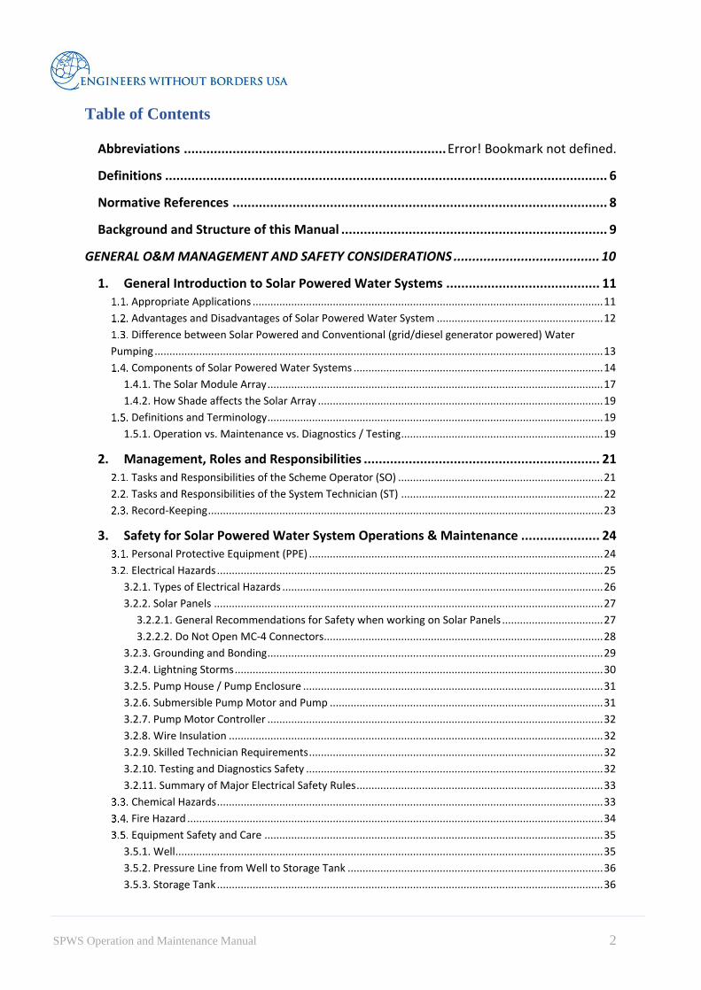
3.2.11. Summary of Major Electrical Safety Rules
Table 3. Summary of Major Electrical Safety Rules
⚠
Energized systems can be lethal when handled inappropriately even if they
appear to be unpowered. Always take extreme care and treat electrical systems
with extreme caution!
⚠
Although proper grounding helps remove shock hazards, Scheme Operators
(SO) and users of the solar powered water system should never remove any
electrical equipment covers. If removed covers or uninsulated wiring are found,
do not touch these components. Immediately contact a certified System
Technician (ST) for support!
⚠ Never service a solar powered water system during a lightning storm!
⚠ Intrusion of any foreign material into the well may result in sickness or death of
system users or severe harm to the system equipment!
⚠
Solar panels have unique characteristics that make them difficult to work on
safely. Adhering to safety guidelines is of utmost important since solar panels
are energized anytime the sun is up. Doing maintenance during night hours is
not safe or practical!
⚠ Never break load or fault currents with the MC-4 connectors. MC-4 connectors
are not designed to open when load is flowing through the connector!
Chemical Hazards Of primary concern is the handling of chlorine or fuel.
Never climb a ladder with an open container of chlorine.

34 SPWS Operation and Maintenance Manual
Always use gloves, eye-wear (in case of splash), and a respiratory mask when working with
chlorine or fuel.
If a chemical burn occurs the following are instructions for minor burn management from the
Burn Injury Resource Centre6. For major burns, the person should be immediately transported
to the nearest clinic or hospital.
First aid should be administered as soon as a chemical burn has occurred.
1. Remove the cause of the chemical burn.
2. For liquid chemicals, remove any clothing or other items that the chemicals may have
spilled on. Wash thoroughly any chemicals off the skin under running water for 15-30
minutes.
3. For dry chemicals, wash the area with a large amount of water to flush the chemical
from the skin; don’t use small amounts of water as they may activate the chemicals. If
there is no water then brush the dry chemical with a clean cloth.
4. Loosely cover the burn with a dry, sterile bandage.
5. If the chemical gets into the eyes, the eyes should be flushed with water immediately,
continue flushing the eyes with running water and get medical help immediately, if
there are contact lenses try to remove them.
6. If the chemical substance is swallowed or inhaled, seek medical attention
immediately.
7. Minor chemical burns will generally heal without further treatment.
8. Don’t do the following: a) Apply any household remedy to a chemical burn. b) Break
blisters or remove dead skin from a chemical burn.
9. For a Call your doctor and/ or proceed to the nearest ER.
Fire Hazard Due to the handling of fuel for the generator, fire hazards are also present. It is imperative that
flames, including cooking stoves, are kept at a minimum distance of 5m from the Pump House
(where the generator is housed) at all times.
Never attempt to extinguish a fuel fire with water.
A bucket with sand should be kept in the pumphouse to soak up fuel spills and to extinguish
small fuel fires.
If a fire breaks out and a person suffers minor burns the following advice is given by the Mayo
Clinic 7for treating minor burns. If a major burn occurs, the person should immediately be
transported to the nearest clinic or hospital.
1. Cool the burn. Hold the burned area under cool (not cold) running water or apply a
cool, wet compress until the pain eases.
6 https://www.burn-injury-resource-center.com/chemical-burns-part-ii/ 7 https://www.mayoclinic.org/first-aid/first-aid-burns/basics/art-20056649

35 SPWS Operation and Maintenance Manual
2. Remove rings or other tight items from the burned area. Try to do this quickly
and gently, before the area swells.
3. Don't break blisters. Fluid-filled blisters protect against infection. If a blister breaks,
clean the area with water (mild soap is optional). Apply an antibiotic ointment. But if
a rash appears, stop using the ointment.
4. Apply lotion. Once a burn is completely cooled, apply a lotion, such as one that
contains aloe vera or a moisturizer. This helps prevent drying and provides relief.
5. Bandage the burn. Cover the burn with a sterile gauze bandage (not fluffy cotton).
Wrap it loosely to avoid putting pressure on burned skin. Bandaging keeps air off the
area, reduces pain and protects blistered skin.
6. If needed, take an over-the-counter pain reliever, such as ibuprofen (Advil, Motrin
IB, others), naproxen sodium (Aleve) or acetaminophen (Tylenol, others).
7. Watch for signs of shock. If the person shows signs of shock such as disorientation,
he or she may have sustained worse injuries than it appears and should be
immediately transported to the nearest clinic or hospital.
Equipment Safety and Care The following sections focus on safety of system components. Figure is a simplified drawing
of the solar powered water system showing its major components and associated risks.
Figure 12. Solar Pumping System Schematic
3.5.1. Well Well safety focusses on preventing contamination due to the introduction of harmful materials
at the wellhead.
Intrusion of any foreign material into the well may result in sickness or death of
system users or severe harm to the system equipment.

36 SPWS Operation and Maintenance Manual
A protective cover and a casing extending above ground level will provide adequate protection,
as illustrated in Figure . Construction of a well enclosure, such as a pump house will further
protect the well and well water quality.
Figure 13. Example of a Well Casing Seal from Jue Water System, Arua District, Uganda.
3.5.2. Pressure Line from Well to Storage Tank The pressure line runs from the well to the top of the storage tank. The pump normally includes
a one-way (non-return) valve that prevents the water in this line from draining back into the
well. Breakage of this line will result in large water losses because of high pressures in the line
caused by the elevation difference between the storage tank and well.
3.5.3. Storage Tank
The storage tank should be considered a confined space and should never be entered
by personnel.
The storage tank is normally sized to handle between one to three days demand. One safety
consideration for this system is structural failure over time where large parts of the tank lose
structural integrity when personnel or users are near the tank. Close monitoring of this structure
is required to mitigate this risk. Instructions for monitoring are provided in the detailed sections
for SO Scheme Operators and ST Technicians below.
3.5.3.1. Ladder Safety
It is dangerous to climb to heights over 2 meters. Do not carry tools or containers when
climbing the ladder to the tank. Ensure you always have three points of contact with the ladder
when climbing. Wear suitable footwear and the necessary PPE.

37 SPWS Operation and Maintenance Manual
3.5.4. Distribution System The gravity supplied distribution system is made up of distribution pipes connected to water
delivery points. Delivery points may range from simple pipe stands for stored water access to
more complex components such as connections to schools, businesses, and healthcare facilities
as examples. The distribution system makes up the largest part of the geography of the water
delivery. Safety considerations of this system are associated with the entrance of contaminants
into the water delivery and the risk of draining the stored water in the storage tank. The
monitoring of this system for breakage, above ground exposure to damage from uncovering
the pipe, leakage from pipe connections, valves, pipe stands, customer delivery connection
equipment and blockage because of the smaller pipe sizes.
Personal Safety Personal safety is of great concern, particularly in remote areas. To ensure your safety and
reduce risks to your person:
• Ensure a clean environment clearing the area, including a radius around the fence, to
reduce risk of insect, rodent, or snake infestation.
• Ensure the area is locked at all times, particularly at night.
• Post the necessary hazard signs around the compound to remind yourself and warn
others of the danger.
• Prepare with your management an emergency response plan should attack or theft
occur.
38 SPWS Operation and Maintenance Manual
OPERATION AND MAINTENANCE ACTIVITIES:
SYSTEM OPERATOR

39 SPWS Operation and Maintenance Manual
4. Routine Operation and Preventative Maintenance
General Guidance The following section details the operations and maintenance tasks for each component of a
solar pumping system. These tasks are typically performed by a “Scheme Operator” who is
responsible for the daily routine operation of the system and for basic preventive maintenance
of system components. A summary of these tasks is included as an attachment following this
section: Daily Activities and Daily Checklist. Additional daily routines may be required by the
system management that may supplement, complement, or replace this checklist. Follow
management instructions on the daily requirements for each specific system. Operation of solar
pumping systems includes both activities related to running the water service, such as operating
technical equipment, and inspection and monitoring activities, such as meter reading and record
keeping. Inspection and monitoring activities must be performed to identify problems in time
to take corrective action before major breakdowns or contaminations occur.
Data about the system’s performance should be regularly logged to identify any deterioration
of the system over time. Recorded data should include all parameters available such as:
• Dynamic Water Level
• Pump Start/End Time
• Water Meter Start/End reading
• Total Run hours and Production (Solar)
• Total Run hours and Production (Generator)
Always include the date and time that a recording is made to better understand how the system
is changing with time. This data will be captured either in the daily or weekly checklists as well
as in system management required additional checklists.
The guidelines below apply to most solar pumping systems. However, maintenance of pumps
depends on the type of pump and energy supply, the type and design of the well, and finally of
the overall design of the scheme and daily demand. Thus, Scheme Operators should adhere to
the guidelines in this document as well as instructions in the manual and safety guidelines of
the pump manufacturer.

40 SPWS Operation and Maintenance Manual
Routine / Daily Operation
Table 4. Regular Operation, Inspection and Preventative Care Daily Activity Sheet
System Component Daily Routine Activities
General
Follow the official pumping schedule for the operating mode of
the scheme.
Note: Normal operation will not require intervention of the Scheme
Operator, but failure of float switch or operation on emergency diesel
may require the Scheme Operator to follow manual schedules
determined for each site.
Solar Array Check if solar panels need washing.
Check for debris on panel surface and any resulting damage.
Well / Wellhead
Record Dynamic water level before starting pumping in the
morning, when switching to generator power, and at the end of
the day.
Pump
Record pumping times.
Record pump pressure when running.
Water meter Record water meter reading at the beginning and end of each
pumping cycle (solar and generator).
Controllers / Inverters, etc.
General Note: When switching between solar and generator
power, it is best to let the pump sit for two minutes as the voltage
rush may damage the pump.
Record electrical device LED status, input and output voltage,
current and power if available on controller and/or inverter.
Check and record any warning lights or alarms.
Pump house Maintain a clean facility at all times.
Tank / Distribution System Check for evidence of tank overflow (e.g. wet ground, erosion).
Check for tank level falling below normal operating conditions.
4.2.1. Daily Water Production Record The daily water production record is usually required by system management and would look
similar to the example on the following page. This record is important for assessing the water
usage, supply, and recharge of the system.

Daily Water Production Record

4.2.2. Capturing Water Production Data Capturing the water production data is a simple routine that requires capturing the time, water
meter reading and three times per day checking the dynamic water level in the well.
Tools required:
o Piezometer
o Clock
o Calculator
o Record sheet
o Pen or pencil
It is important to inform the system supervisor or system management should any of the
equipment fail to show readings or if any of the tools become broken, lost or otherwise
inoperable.
4.2.2.1. How to use a Piezometer
The piezometer is used in ground water level measurement in boreholes. It consists of a pipe
that is sealed along its entire length and installed in a borehole such that it must be open to
water flow at bottom and open to atmosphere at the top.
To measure the water level:
• Lower the water level sounder probe from the surface with the help of the connecting
flat cable for taking observations.
• Record reading when it makes contact with water. A buzzer sound will sound and an
LED light will come on, both located on the reel.
Figure 13. Piezometer example

43 SPWS Operation and Maintenance Manual
4.2.2.2. How to read the Water Meter
The water meter installed at each point may be slightly different, but they will all show the
same, or similar, things. The most important is the M3 of water that has passed through the
pipes since the meter was installed. This is identified as below. It is this number that is recorded
in the water production record. The other, smaller dials on the meter show water flow and
sometimes also water loss.
8
4.2.3. Daily Record/Checklist The daily record sheet, different from the water production record captures data important to
assessing the overall efficiency of the system and to provide an opportunity for early detection
of potential minor and major system flaws.
Date: System:
Conducted By:
System Component Activity Check
Completed
Notes/Repairs
Solar Photovoltaic
Array
Wash panels.
Is there any exposed or lose or
disconnected wiring? Check for any
damage from rodents or animals.
Pump
(over and above
regular operations
procedures provided
by operator)
Is pump or discharge piping leaking?
Record pump pressure when running.
10.00 12:00 14:00 16:00
8 https://www.wessexwater.co.uk/your-account/water-meters/reading-your-meter

44 SPWS Operation and Maintenance Manual
Controllers/Inverters
Record electrical Power
10.00 12:00 14:00
Note any faults or error alarms
Pumphouse / Pump
Enclosure
Check area around pump and pumphouse
for trash and debris.
4.2.3.1. Solar Panel Care
1. Check for a source of shading on the panels
such as vegetation or structures.
Visually inspect the area for possible
sources of shade.
Note that shading of even one panel will
reduce power from all panels because of
the electrical properties of the
connections.
Trim or remove any vegetation around
the solar panels as well as any erection
of structures that will block sunlight.
2. Wash panels.
Wash during early hours when it is not yet hot.
Remember to remove jewellery, belts, etc that may scratch the
panels.
Make sure the ladder you are using is in good repair.
Use a soft sponge and water only. DO NOT USE SOAP.
Squeegee dry the panels to ensure that water spotting does not
occur during drying.
3. Check if the panels are cracked.
If yes, contact the System Technician (ST) to request support.
4.2.3.2. Pump
Check if pump or discharge piping leaks.
Visually inspect connections at wellhead for leaks.
Contact System Technician (ST) to fix leaks.
Due to the high pressure at the pump repairs to the discharge pipe require shutting
the system down which should only be attended to by the System Technician.
Record pump pressure when pump is running.
View pump pressure on pump pressure gauge.
If pressure is outside of expected range, contact System Technician (ST).
Figure 14. Example of a Dirty and
Shaded Solar Panel
Figure 15. Squeegee

45 SPWS Operation and Maintenance Manual
Expected range will be different for each
system. “Expected range” is the pressure
you normally record. For example, if every
day the pressure records around 8 Psi, but
suddenly the pressure drops to 4 Psi, this
indicates a problem that should be
addressed immediately.
4.2.3.3. Pump Controller (Inverter)
1. Record electrical LED status, input and output,
current and power if available on controller
and/or inverter.
Check for readings which differ
significantly from normal recoded data.
If the electrical discharge is not in the expected range,
request technical support.
For example, if the voltage usually reads 502.7, like the
example shown, and suddenly the voltage drops to 300,
this means that there is either a problem with the panels
(if during midday when sun in strong and there is no
shade or cloud cover), or, if the pump is not running,
that it is time to switch the system to the generator. If
the pump is still running, record the data and keep an
eye on the system for signs of shutting down.
Check for Alarms
Most common alarms (red LED lights) will show one of the two following
indicators:
• FAULT, or
• WELL DRY
If the error reads “WELL DRY”, call the System Technician.
If the error reads “FAULT”, check to see if the pump is running*9. If the pump is
running, the pressure shows in normal range and there are no unusual sounds, then
it could be that the inverter has an internal error, contact the System Technician.
If the pump is not running, the system may need to be re-started.
To re-start the system, the system operator will then refer to the re-start
procedure in the manufacturers operating manual to restart the specific
equipment at their site.
4.2.3.4. Daily Pump and Pump House Activities
Check area around pump for trash and debris.
Remove and dispose of trash and debris.
This is important to ensure that insects, rodents or snakes do not disturb regular
operation or cause physical harm.
9 *Check also the trouble-shooting guide in Section 5.
Figure17. Example Pump
Controller Display
Figure 16. Example of a Pump Pressure
Gauge at the Jue Water System4

46 SPWS Operation and Maintenance Manual
Regular (Weekly) Operations and Preventative Care The following sections outline normal daily or weekly operations of the solar pumping system
and should be followed as a general guideline supplemental to manufacturer’s specific
guidelines and management directions. The instructions in this section include detailed
information on daily data collection.
This section is organized to follow the natural flow of the energy and the water, so starting with
the solar array and ending at the distribution points (tap stands).
Figure 18. System Components

47 SPWS Operation and Maintenance Manual
4.3.1. ROUTINE (WEEKLY) ACTIVITY SHEET
System Component Inspection Result Action / Response
Solar Photovoltaic
Array
Check for a source of shade on the
panels such as vegetation or
structures.
Trim or remove any vegetation
around the solar panels as well as
any erection of structures that will
block sunlight.
Check area around solar panels for
debris for trash and debris and spider
webs or any other insect nesting.
Remove and dispose of trash and
debris. Carefully remove webs and
nests.
Wash panels.
Do during early hours when it is
not yet hot. Use a soft sponge and
water only.
Are there any cracks in the panels? If yes, request technical support
from ST.
Is there any exposed or lose or
disconnected wiring? Check for any
damage from rodents or animals.
If yes, request technical support
from ST.
Is the panel mounting strong and well
attached? Are there cracks or any
other sign of weakening?
If yes, request technical support
from ST.
Well / Wellhead
Check to ensure well head has not
been damaged, exposing the user to
potential bacteria or serious illness as
a result.
If any sign of damage is showing,
contact the System Technician
(ST) to request support.
Pump Check area around pump for debris
for trash and debris.
Remove and dispose of trash and
debris.
Controllers/Inverters,
etc Clean protective box
If there is any sign of electrical
burn, contact System Technician.
Plug any holes.
Pump house / Pump
Enclosure
Check enclosure for cracks and
damage?
If cracked repair cracks with
cement.
Pressure
line
Are any pipes exposed? If yes, bury pipe.
Are any valves leaking? If yes, request technical support
from ST.
Are any pipes leaking? If yes, request technical support
from ST.
Are any connections leaking? If yes, request technical support
from ST.
Are any valves stuck (cannot be
moved), loose, or missing?
If yes, request technical support
from ST.

48 SPWS Operation and Maintenance Manual
Chlorine Doser
Are there any blockages in the inlet?
If there is any sign of blockages due
to dirt, clean the tank and the inlet
pipe
Has the solution tank lid been
damaged or removed?
If the lid is missing replace the lid
or place a purchase order for a new
lid.
Is it leaking? If yes, request technical support
from ST.
Has the dosing rate increased or
dropped significantly?
If yes, request technical support
from ST.
Tank
Has the tank lid been damaged or
removed?
If the lid is missing replace the lid.
If the lid is damaged request
technical support to fix the lid or
place a purchase order for a new
lid.
Is the tank (itself) cracked or leaking? If yes, request technical support
from ST.
Are connections to the tank leaking? If yes, request technical support
from ST.
Is the tank stand (support) damaged
in any way?
If yes, request technical support
from ST.
Is the tank leaning? If yes, request technical support
from ST.
Distribution Line
Are any pipes exposed? If yes, bury pipe.
Are any valves leaking?
If the valve is loose, tighten the
fittings, If the fittings still remove
valve and replace gasket. Replace
entire valve as necessary.
Are any pipes/connections leaking?
If the pipe is leaking at a fitting,
tighten the fitting. If the leak
continues, request technical
support.
Are any valves stuck (cannot be
moved), loose, or missing?
If yes, follow instructions for
repair.
Taps and Standpipes
Are any taps loose? If yes, tighten tap.
Are any taps leaking?
If yes, tighten tap. If it continues to
leak replace gasket or entire tap as
necessary.
Are any taps stuck or blocked? If yes, replace tap.

49 SPWS Operation and Maintenance Manual
Are any tap handles missing? If yes, replace handle/replace tap.
Are any standpipes leaning or falling
over?
Straighten and construct support
for tap stand or secure to existing.
4.3.2. Solar Panels
Check if wiring is exposed, loose/sagging, or disconnected. Check if wires were damaged by
rodents or animals.
If yes, contact the System Technician (ST) to request support.
Check if the panel mounting is strong and well attached. Check for cracks or any other sign of
weakening.
Check and tighten loose bolts.
If signs of rust are showing, repaint the area with anti-corrosive paint to avoid
further weakening from rust.
If there are any visible areas of weakness, contact the System Technician (ST) to
request support.
Check the area around solar panels for trash and debris, spider webs or any other insect nesting.
Remove and dispose of trash and debris.
Carefully remove spider webs and insect nests. Call a beekeeper or someone who
can handle dangerous insect.
4.3.3. Lightening Arrestor and Grounding
Check to make sure the Lightening arrestor is secure, without risking to fall and damage the
solar panels.
Check to ensure that the grounding rod/s are secure and have no signs
of damage.
If there are any visible signs of damage or disconnection, these
could be costly or deadly, contact the System Technician (ST) to
request support.
4.3.4. Well head Check to ensure well head has not been damaged, exposing the user to potential bacteria or
serious illness as a result.
If any sign of damage is showing, contact the System Technician (ST) to request
support.
If the well head has been damaged and there is a possibility of entry wither by dirt,
insects or animals, the well may need to be flushed.
This is a serious problem. Do not take it lightly.

50 SPWS Operation and Maintenance Manual
4.3.5. Submersible Pump and Motor The majority of necessary regular controls and preventative care measures for the pump are
completed on a daily basis to ensure smooth functionality and reliability of the pump. However,
each pump will have its own manufacturer recommendations, detailed in the manufacturer
manuals. Pump failure will require the trouble-shooting of the technician or pump
supplier/mechanic.
4.3.6. Pump Controller / Inverter Inspect the wiring for potential failures, damage, or exposed wires.
Clean the inverter box.
Remove dust and cobwebs
Repair holes so that insects or rodents cannot enter and nest causing serious damage to
the equipment.
If any sign of damage to wiring, contact the System Technician (ST) to request
support.
If there appears to be a burnt fuse, or
if there appears to be any blackened
areas indicating an electrical burn,
there may be a wiring fault. Contact
the System Technician (ST) to
request support.
4.3.7. Pump House / Pump Enclosure
1. Check enclosure for cracks and damage.
Physically walk around the pump
house inspecting the walls
foundations and roof, entrances and exits of any piping looking for any sign of
damage.
Minor foundation, wall, or other concrete cracks or issues identified can usually be
repaired with mortar.
Roof damage may require replacement or repair of roofing material, depending on
the problem.
Check if the enclosure lock is functional.
Lock enclosure, replace lock and/or repair locking hardware as necessary.
4.3.8. Pressure Line from Well to Storage Tank Physically walk the pressure line from the pump to the tank, while checking for the following
problems:
Check Air release valve
Make sure valve is not blocked
Figure 19. Example of Damaged and
Leaking Piping Outside a Pump House

51 SPWS Operation and Maintenance Manual
Ensure during pumping the valve exhausts air and closing without excessive
leakage
Check the drain valve annually, if it expels air, contact the System Technician to
request support
During maintenance close the shutoff valve
1. Check backwash valve
Ensure no leakage. If yes, contact the System Technician (ST) to request support.
Ensure the gate valve towards the riser pipe is closed
Ensure back wash pipe has end cap to block out vermin.
2. Check if valves are leaking.
If yes, contact the System Technician (ST) to request support.
3. Check if pipes are leaking.
Look for obvious signs of leakage, i.e. wet ground or puddles, as you walk the line
for inspection.
If yes, contact the System Technician (ST) to request support.
4. Check if any pipes are exposed.
If any pipes are exposed, re-bury the pipe by carefully re-digging the trench around
and beneath the pipe, burying the pipe and covering it again with dirt.
Ensure that the pipe has not been damaged while exposed by inspecting the area
for visible signs of leakage or running the pump and watching the pipe for leakage.
If the pipe has been damaged, contact the System Technician (ST) to request
support.
5. Check if connections are leaking.
Visually inspect for signs of leakage at the surface.
If yes, contact the System Technician (ST) to request support.
6. Check if any valves are stuck (cannot be moved), loose, or missing?
If yes, contact the System Technician (ST) to request support.
Because the pressure line is pressurized, most repairs will require a System Technician
(ST) to restrict water flow at the pump house.
4.3.9. Chlorine Dosser
1. Check for blockages in the inlet
If there is any sign of blockages due to dirt, clean the tank and the inlet pipe
2. Check if lid of chlorine solution tank lid is damaged or removed?
If the lid is missing replace the lid or place a purchase order for a new lid.
3. Check the dosing rate increased or dropped significantly?
If yes, request technical support from ST.
4. Check if leaking?
If yes, request technical support from ST.

52 SPWS Operation and Maintenance Manual
4.3.10. Storage Tank
1. If the tank lid is easily accessible, check if it has been damaged or removed.
If the lid is missing replace the lid.
If the lid is damaged contact the System Technician (ST) to fix the lid or place a
purchase order for a new lid.
Check if the tank is cracked or leaking.
Conduct a visual inspection of the tank and its surrounding ground to look for
visible signs of leakage.
If yes, contact the System Technician (ST) to request support.
Check if the tank connections are leaking.
If yes, contact the System Technician (ST) to request support.
Check for damage to the tank support structure.
If yes, contact the System Technician (ST) to request support.
Check if the tank is leaning.
If yes, contact the System Technician (ST) to request support.
4.3.11. Distribution System Physically walk the distribution lines from the tank to each of the distribution points, checking
for the following problems. If distribution lines must be repaired, close the tank outlet or
distribution valve at the location in need of repair to interrupt water supply and perform repairs.
Ensure that replacement parts are the same pipe type and size as the original parts.
1. Close and open tank discharge valve on distribution side of tank outlet (mainline).
Open and close valve slowly to maintain the integrity of the valve and prevent the
water hammer effect.
If any stiffness or leaks found, repair and replace parts as necessary.
Check if pipes are exposed.
If yes, bury pipes.
Check if any valves are leaking.
If the valve is loose, tighten the fittings carefully to ensure fittings are snug but not
overtightened so as to reduce the thread quality and risk further leakages.
If the fittings still leak, remove valve and replace gasket.
Replace entire valve as necessary.
Check if any pipes/connections are leaking.
If the pipe is leaking at a fitting, tighten the fitting.
If the leak continues, replace the fitting.
Check if any valves are stuck (cannot be moved), loose, or missing.
If yes, repair or replace the valve.
Check for low flow or low pressure at use points.
Low pressure or flow may indicate leakage.

53 SPWS Operation and Maintenance Manual
4.3.12. Taps and Tap Stands If taps or tap stands must be repaired, close the tank outlet or distribution valve at the location
in need of repair to remove water supply and perform repairs. Ensure that replacement parts
are the same pipe type and size as the original parts.
1. Check if taps are loose.
If yes, tighten tap.
Check if taps are leaking.
If yes, tighten tap.
If it continues to leak replace gasket or entire tap as necessary.
Check if taps are stuck or blocked.
If yes, replace tap.
Check if tap handles are missing.
If yes, replace handle/tap.
Check if standpipes are leaning or falling over.
Straighten and construct support for tap stand or secure to existing support.

54 SPWS Operation and Maintenance Manual
5. Trouble-Shooting and Minor Repair
Finding the root cause of any malfunction is an important first step towards finding a good
solution. During trouble shooting where there is risk of contact with electricity, always shit off
the electricity and in addition, wear the necessary PPE. The table below shows common issues,
their possible causes and the steps needed to diagnose and fix the problem.
Table5. Trouble-shooting and Minor Repair
Issue/Problem Possible cause Diagnosis and Fix
Well pump won’t
start.
No power to switch
box.
1. Ensure that the main electrical disconnect arm
(main switch) is in the up (energized)
position.
2. If the main switch is facing down, the system
is shut off.
3. Return to on position with arm facing up.
4. If problem continues, contact Technician.
Circuit breaker or
overload relay tripped.
1. Open control panel.
2. Find the circuit breaker that has “tripped” (is
in the down position).
3. Reset breaker or overload relay (return to up
position).
4. If the breaker continues to trip, contact
Technician.
Burned out fuse. 1. Pull down (de-energize) the main electrical
disconnect arm (main switch) before opening
the panel and replacing the fuses.
2. Open the panel to identify the burnt fuse (a
burnt fuse will appear slightly burned).
3. If none of the fuses appear burned, remove
and replace each fuse ensuring a strong
connection.
4. If neither of these are the problem, contact
Technician.
5. If fuses continue to burn out, contact
Technician.
Short, broken or loose
wire.
Notify Technician.
None of the Above Notify Technician!

55 SPWS Operation and Maintenance Manual
Well pump starts
and stops too
frequently
(excessive cycle
rate).
Leaking foot valve or
check valve.
With the pump off, listen for water running back
into the well and check the water flow meter and
see if it is running backward.
Pump pressure
has increased
Closed or partially
closed valves, blocked
or partially blocked
pipe, along pressure
line.
Walk the transmission line to see if there is an
obvious problem. Ensure all valves are fully
open. Notify Technician.
Change over
switch is over-
heating
Current reaching
switch is greater than
that for which the
switch is rated.
Notify Technician.
Inverter is
Overheating
Blocked ventilation
due to dust in the
inverter fins
Regularly check the cooling fins during the
operational period and to establish that the
cooling or ventilation system is actually
operating correctly.
Installing and cleaning dust filters and removing
undergrowth that impedes airflow, etc.
Inverter Isolation
Fault
Short-circuit between
various parts of the
circuit due to moisture
and damage to the
sleeve on the cabling,
faulty installation,
poor connection of the
DC cables to the
panel, or moisture in
the connection part of
the PV module more
common in areas with
high humidity and/or
close to the sea.
Ensure DC cables are of high quality and
correctly installed, i.e. that the cable bushing is
watertight and correct level of protection (IP) is
selected for the inverter cabinet and the inverter
building.
Notify Technician.

56 SPWS Operation and Maintenance Manual
Inverter does not
restart after a grid
fault
voltage peaks which
occur during sudden
deactivation could
trigger cut-outs in the
system
Notify Technician.
Tank is
overflowing.
The float switch may
be defective.
Notify Technician.
Connections
to/from tank are
leaking.
Gasket deterioration Notify Technician.
Tank is leaning or
pedestal is
damaged.
Physical damage Notify Technician.
Taste and odour
complaints.
Long detention time.
Growth of algae or
other organisms.
Contaminant entry.
Leaching from
internal coatings or
new concrete tank.
Source water potential
for taste and odour
such as high levels of
hydrogen sulphides.
Notify Technician.
High Chlorine
content during
water testing at
distribution points
Water is insufficient
for dilution.
Chlorine dosage is too
high.
Add more chlorine until Technician has verified
problem.
Notify Technician.
Red water. Metals uptake from
metal surfaces from
lack of or improper
cathodic protection.
Iron or manganese.
Notify Technician.
Sand sediment in
the water.
Notify Technician.

57 SPWS Operation and Maintenance Manual
Water appears
turbid or a light
tan colour.
Storage tank /
reservoir is
contaminated or rusty.
Notify Technician.
Surface water entering
or influencing well.
Notify Technician.

58 SPWS Operation and Maintenance Manual
Regular Inspection and Preventative Care DAILY ACTIVITY SHEET
System Component Daily Routine Activities
General
Follow the official pumping schedule for the operating mode of the
scheme.
Note: Normal operation will not require intervention of the Scheme Operator,
but failure of float switch or operation on emergency diesel may require the
Scheme Operator to follow manual schedules determined for each site.
Solar Array Check if solar panels need washing.
Check for debris on panel surface and any resulting damage.
Well / Wellhead Record Dynamic water level before starting pumping in the morning,
when switching to generator power, and at the end of the day.
Pump
Record pumping times.
Record pump pressure when running.
Water meter Record water meter reading at the beginning and end of each pumping
cycle (solar and generator).
Controllers / Inverters, etc.
General Note: When switching between solar and generator power, it is
best to let the pump sit for two minutes as the voltage rush may damage
the pump.
Record electrical device LED status, input and output voltage, current
and power if available on controller and/or inverter.
Check and record any warning lights or alarms.
Pump house Maintain a clean facility at all times.
Tank / Distribution System Check for evidence of tank overflow (e.g. wet ground, erosion).
Check for tank level falling below normal operating conditions.

Regular Inspection and Preventative Care DAILY WATER PRODUCTION RECORD

Regular Inspection and Preventative Care DAILY CHECKLIST
Date: System:
Conducted By:
System Component Activity Check
Completed
Notes/Repairs
Solar Photovoltaic
Array
Wash panels.
Is there any exposed or lose or
disconnected wiring? Check for any
damage from rodents or animals.
Pump
(over and above
regular operations
procedures provided
by operator)
Is pump or discharge piping leaking?
Record pump pressure when running.
10.00 12:00 14:00 16:00
Controllers/Inverters
Record electrical Power
10.00 12:00 14:00
Note any faults or error alarms
Pumphouse / Pump
Enclosure
Check area around pump and
pumphouse for trash and debris.

Regular Inspection and Preventative Care ROUTINE (WEEKLY) ACTIVITY SHEET
System Component Inspection Result Action / Response
Solar Photovoltaic Array
Check for a source of shade on the
panels such as vegetation or
structures.
Trim or remove any vegetation
around the solar panels as well
as any erection of structures
that will block sunlight.
Check area around solar panels for
debris for trash and debris and spider
webs or any other insect nesting.
Remove and dispose of trash
and debris. Carefully remove
webs and nests.
Wash panels.
Do during early hours when it
is not yet hot. Use a soft
sponge and water only.
Are there any cracks in the panels? If yes, request technical
support from ST.
Is there any exposed or lose or
disconnected wiring? Check for any
damage from rodents or animals.
If yes, request technical
support from ST.
Is the panel mounting strong and well
attached? Are there cracks or any
other sign of weakening?
If yes, request technical
support from ST.
Well / Wellhead
Check to ensure well head has not
been damaged, exposing the user to
potential bacteria or serious illness as
a result.
If any sign of damage is
showing, contact the System
Technician (ST) to request
support.
Pump Check area around pump for debris
for trash and debris.
Remove and dispose of trash
and debris.
Controllers/Inverters, etc Clean protective box
If there is any sign of electrical
burn, contact System
Technician.
Plug any holes.
Pump house / Pump
Enclosure
Check enclosure for cracks and
damage?
If cracked repair cracks with
cement.
Pressure
line
Are any pipes exposed? If yes, bury pipe.
Are any valves leaking? If yes, request technical
support from ST.
Are any pipes leaking? If yes, request technical
support from ST.
Are any connections leaking? If yes, request technical
support from ST.

Are any valves stuck (cannot be
moved), loose, or missing?
If yes, request technical
support from ST.
Chlorine Doser
Are there any blockages in the inlet?
If there is any sign of blockages
due to dirt, clean the tank and
the inlet pipe
Has the solution tank lid been
damaged or removed?
If the lid is missing replace the
lid or place a purchase order
for a new lid.
Is it leaking? If yes, request technical
support from ST.
Has the dosing rate increased or
dropped significantly?
If yes, request technical
support from ST.
Tank
Has the tank lid been damaged or
removed?
If the lid is missing replace the
lid. If the lid is damaged
request technical support to fix
the lid or place a purchase
order for a new lid.
Is the tank (itself) cracked or leaking? If yes, request technical
support from ST.
Are connections to the tank leaking? If yes, request technical
support from ST.
Is the tank stand (support) damaged
in any way?
If yes, request technical
support from ST.
Is the tank leaning? If yes, request technical
support from ST.
Distribution Line
Are any pipes exposed? If yes, bury pipe.
Are any valves leaking?
If the valve is loose, tighten the
fittings, If the fittings still
remove valve and replace
gasket. Replace entire valve
as necessary.
Are any pipes/connections leaking?
If the pipe is leaking at a
fitting, tighten the fitting. If
the leak continues, request
technical support.
Are any valves stuck (cannot be
moved), loose, or missing?
If yes, follow instructions for
repair.
Taps and Standpipes Are any taps loose? If yes, tighten tap.

Are any taps leaking?
If yes, tighten tap. If it
continues to leak replace
gasket or entire tap as
necessary.
Are any taps stuck or blocked? If yes, replace tap.
Are any tap handles missing? If yes, replace handle/replace
tap.
Are any standpipes leaning or falling
over?
Straighten and construct
support for tap stand or secure
to existing.

Regular Inspection and Preventative Care WEEKLY CHECKLIST
Date: Scheme:
Conducted by:
System Component Activity Check
Completed Notes / Repairs
Solar Photovoltaic
Array
Check for a source of shade on the panels
such as vegetation or structures.
Check area around solar panels for debris
for trash and debris and spider webs or
any other insect nesting.
Are there any cracks in the panels? Yes / No
Is there any exposed or lose or
disconnected wiring? Check for any
damage from rodents or animals.
Is the panel mounting strong and well
attached? Are there cracks or any other
sign of weakening?
Well / Wellhead Is there any visible damage to the
wellhead? Yes / No
Pump
Check area around pump for debris for
trash and debris.
Controllers /
Inverters etc.
Clean control box.
Inspect for any signs of damage to wires
or electrical burn.
Pump house /
Pump Enclosure Check enclosure for cracks and damage?
Pressure
line
Are any pipes exposed?
Are any valves leaking?
Are any pipes leaking?
Are any connections leaking?
Are any valves stuck (cannot be moved),
loose, or missing?
Chlorine Doser
Check solution tank for damage or
leakages.
Check dosing rate for significant changes
Tank
Has the tank lid been damaged or
removed?
Is the tank (itself) cracked or leaking?
Are connections to the tank leaking?
Is the tank stand (support) damaged in
any way?

Is the tank leaning?
Distribution Line
Are any pipes exposed?
Are any valves leaking?
Are any pipes/connections leaking?
Are any valves stuck (cannot be moved),
loose, or missing?
Taps and
Standpipes
Are any taps loose?
Are any taps leaking?
Are any taps stuck or blocked?
Are any tap handles missing?
Are any standpipes leaning or falling
over?