This lab involves using software network analyzers to …blough.ece.gatech.edu/4110/lab5.doc · Web...
29
ECE 4110 Internetwork Programming Lab 5: Setting up a Network Using Cisco Routers, Switched and VLAN Technology Group Number: ________ Member Names: _________________________ _________________________ Date Issued: October 3, 2008 Date Due: October 8, 2008 NOTICE: Because there are only three setups, each group will need to sign up for timeslots on the sheets attached to the lab door. You can only sign up for a total of 2 hours (4 slots) at a time, AND YOU MUST USE THE SAME SETUP FOR THE ENTIRE LAB. These can either be in a row or spread out, but no group can have more than 4 slots reserved at any one time. Once one of your slots has expired, you can sign up for another one. See Appendix C for instructions on how to save and reload your work if you need to leave and continue later. Please read the entire lab before you show up to start working on it. Fill this blank in after you make your reservation: We signed up for PLAYSTATION #: ________________ Lab Goals Configure switches and routers on a network Understand VLANs Understand routing and sub-interfaces PART I Section I: Logging into the Routers/Switches All of the routers and switches are accessible from a Digi console CM32. There are three playstatations: playstation1 (Enterprise), playstation2 (Bad ISP/University), and playstation3 (Good ISP). From here on in, they will be referred to as playstationX, where X is the number of the playstation you are working on. The following instructions describe how to access the Digi console CM32 and log into a port which is in turn connected to the console port of the Cisco equipment: 1
Transcript of This lab involves using software network analyzers to …blough.ece.gatech.edu/4110/lab5.doc · Web...
ECE 4110 Internetwork ProgrammingLab 5: Setting up a Network Using Cisco Routers, Switched and VLAN Technology
Group Number: ________
Member Names: _________________________ _________________________
Date Issued: October 3, 2008Date Due: October 8, 2008
NOTICE: Because there are only three setups, each group will need to sign up for timeslots on the sheets attached to the lab door. You can only sign up for a total of 2 hours (4 slots) at a time, AND YOU MUST USE THE SAME SETUP FOR THE ENTIRE LAB. These can either be in a row or spread out, but no group can have more than 4 slots reserved at any one time. Once one of your slots has expired, you can sign up for another one. See Appendix C for instructions on how to save and reload your work if you need to leave and continue later.
Please read the entire lab before you show up to start working on it.
Fill this blank in after you make your reservation: We signed up for PLAYSTATION #: ________________
Lab Goals
Configure switches and routers on a network Understand VLANs Understand routing and sub-interfaces
PART I
Section I: Logging into the Routers/Switches
All of the routers and switches are accessible from a Digi console CM32. There are three playstatations: playstation1 (Enterprise), playstation2 (Bad ISP/University), and playstation3 (Good ISP). From here on in, they will be referred to as playstationX, where X is the number of the playstation you are working on. The following instructions describe how to access the Digi console CM32 and log into a port which is in turn connected to the console port of the Cisco equipment:
You may use any free mini-net computer with your own hard drive inserted into it to communicate with the rack of equipment. In order to connect to the CM32 you need to set up your mini-net’s machine network card to access its network:# ifconfig eth0:0 192.168.254.<100+group #> So group 1 is 192.168.254.101, and so forth. You will need to do this every time you power off your machine. What this does is set up a virtual interface, so you have two IP addresses on one network card. This allows you access to two networks with only one interface card.
You will be using a series of scripts to help you set up the routers and save your work. These scripts are described in detail in Appendix C. First, go to Appendix C and install the scripts (on your hard drive) according to the directions. Once this is done, MAKE SURE NO ONE ELSE IS USING THE PLAYSTATION YOU WANT TO USE. This is very important, as you are about to reset the equipment configuration, and all of their work will be lost.
1
Now that you are sure no one else is using the playstation, reset your chosen playstation by running the reset_pX script in the mnet_tools_v1.5 directory. Several windows should pop up. DO NOT CLOSE THEM UNTIL IT IS SAFE TO DO SO. If you are on playstation 1 or 2, you will get an error in one of the windows about VPN or Firewall processing not being enabled; ignore this for now. Once all of the other windows say it is safe to close them, do so. Now run the download_pX script to save the current configuration. From now on, you’ll run the download_pX script to save your work, and the upload_pX to restore the configuration of the playstation to the last saved state. Before running the upload script, MAKE SURE NO ONE ELSE IS USING THE PLAYSTATION.
Once you have reset your playstation, connect to the CM32:#ssh [email protected] it comes up, Type yes to the RSA question.password: playstationX (Note X is a number)
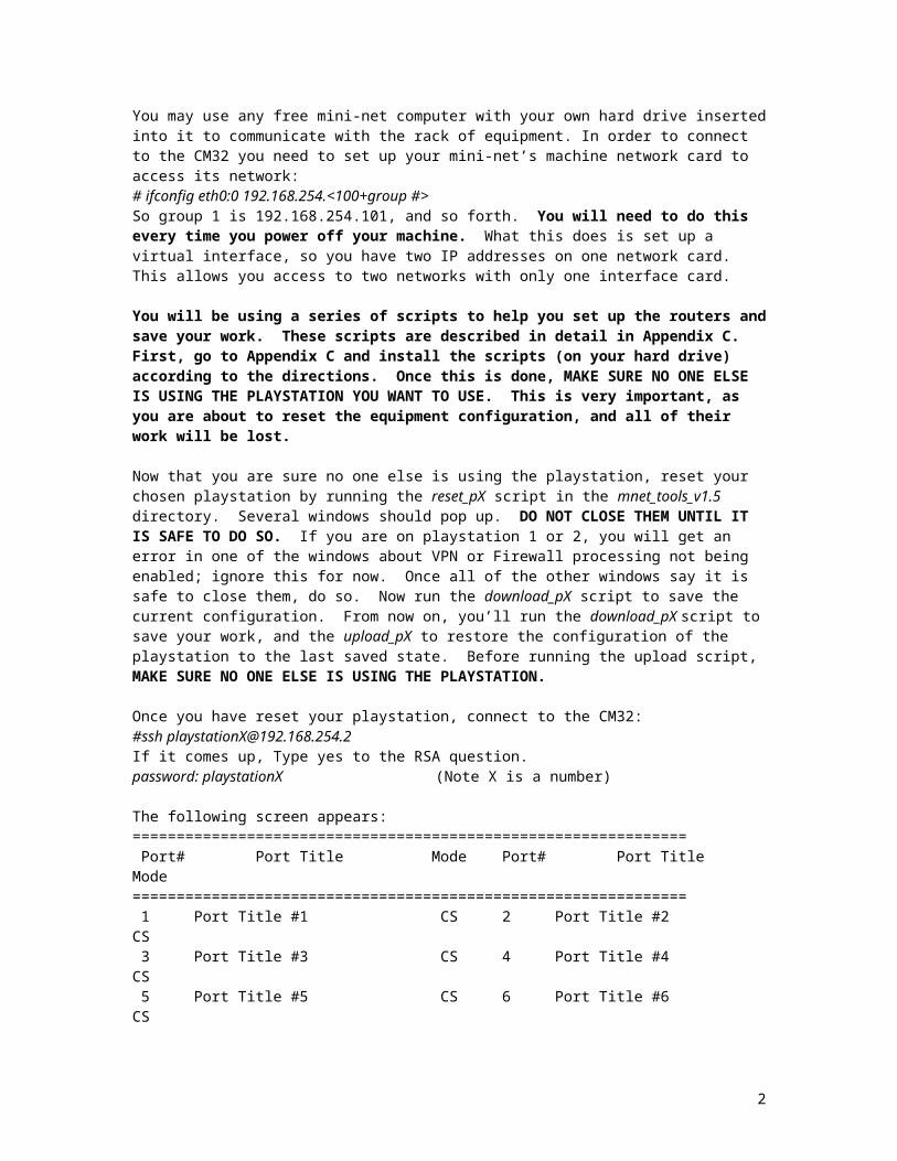
The following screen appears:=============================================================== Port# Port Title Mode Port# Port Title Mode =============================================================== 1 Port Title #1 CS 2 Port Title #2 CS 3 Port Title #3 CS 4 Port Title #4 CS 5 Port Title #5 CS 6 Port Title #6 CS 7 Port Title #7 CS 8 Port Title #8 CS 9 Port Title #9 CS 10 Port Title #10 CS 11 Port Title #11 CS 12 Port Title #12 CS 13 Port Title #13 CS 14 Port Title #14 CS 15 Port Title #15 CS 16 Port Title #16 CS 17 Port Title #17 CS 18 Port Title #18 CS 19 Port Title #19 CS 20 Port Title #20 CS 21 Port Title #21 CS 22 Port Title #22 CS 23 Port Title #23 CS 24 Port Title #24 CS 25 Port Title #25 CS 26 Port Title #26 CS 27 Port Title #27 CS 28 Port Title #28 CS 29 Port Title #29 CS 30 Port Title #30 CS 31 Port Title #31 CS 32 Port Title #32 CS
Enter command (1-32 serial port, others for exit) ------>
Each router/switch has a console port connected to a port on the digiconsole. The digiconsole port numbers are what identifies each router and are printed to the left of each machine on the racks in the back of the room.
Table 1. Console manager port assignmentsPart Console Manger Port AssignmentPlaystation1Cisco 3550 Switch 5Cisco 1760 Router (Mars) 7Cisco 1760 Router (Saturn) 8Cisco 1760 Router (Earth) 9Playstation2Cisco 3550 Switch 14Cisco 1760 Router (Mars) 16Cisco 1760 Router (Saturn) 17Cisco 1760 Router (Earth) 18Playstation3
2
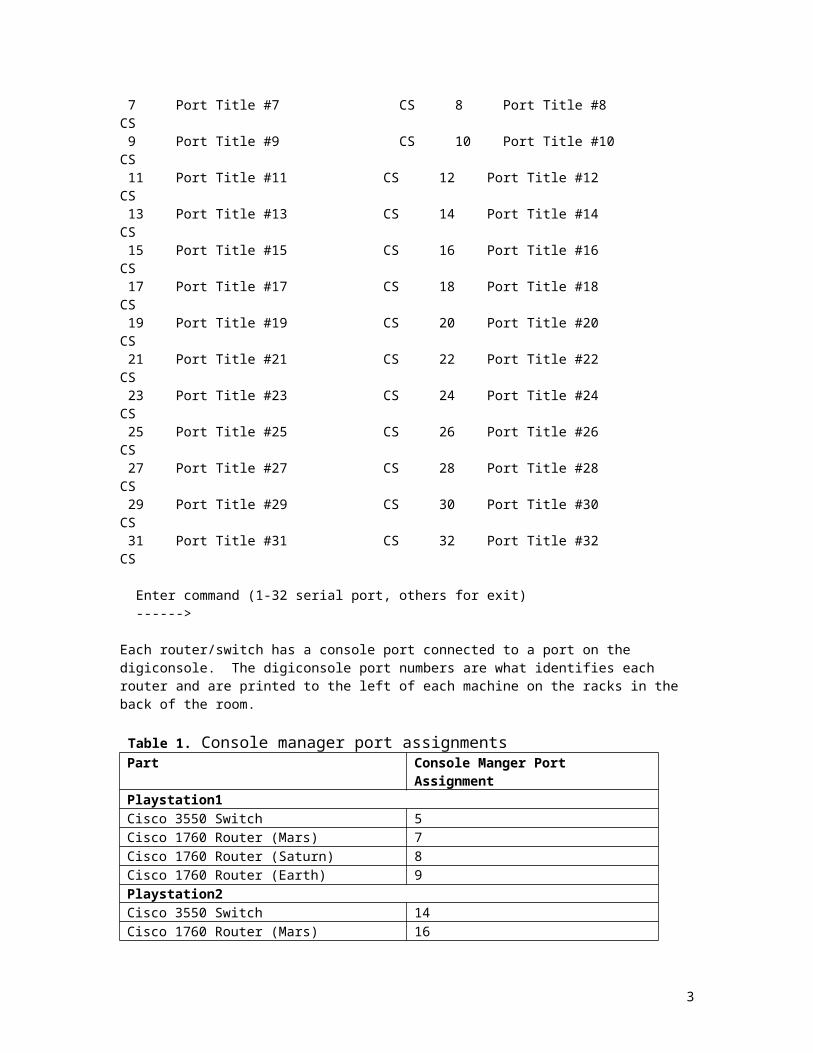
Cisco 3550 Switch 23Cisco 1760 Router (Mars) 25Cisco 1760 Router (Saturn) 26Cisco 1760 Router (Earth) 27
Go to the rack and locate the switch and 3 routers you will be using by the numbers in Table 1. Then, type in the number for the 3550 switch into the port selection screen. You may need to hit <ENTER> a few times to get a prompt. You are now logged into the network device at the port you specified. To log out of that device, type control-Z and then hit x.
Figure 1 shows the network topology that we will be creating with the switch and routers. It shows the three physical routers (Mars, Saturn, and Earth) as well as the 6 VLANs we will be creating on the switch. Go ahead and fill in the Digi #’s for the different components. Make sure you write down the number of the playstation you are working on. (You are only filling in four blanks Digi #______ and the playstation blank at this point in the lab).
Section II: Switch Configuration
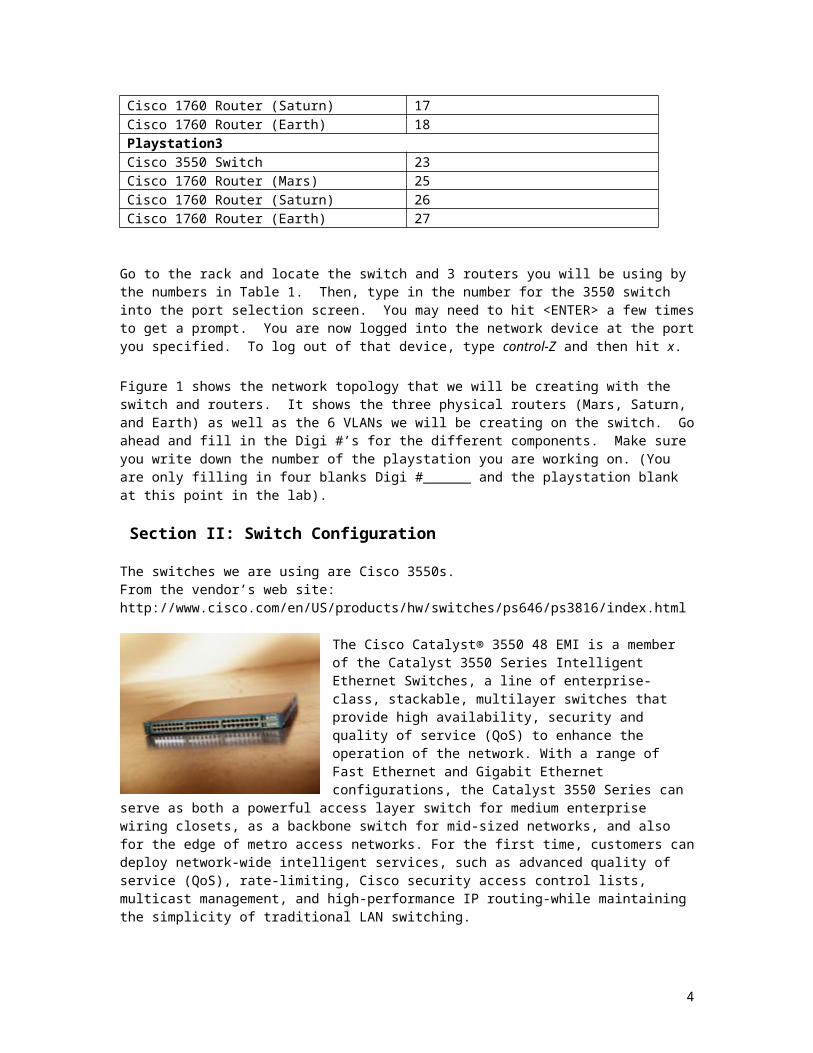
The switches we are using are Cisco 3550s.From the vendor’s web site:http://www.cisco.com/en/US/products/hw/switches/ps646/ps3816/index.html
The Cisco Catalyst® 3550 48 EMI is a member of the Catalyst 3550 Series Intelligent Ethernet Switches, a line of enterprise-class, stackable, multilayer switches that provide high availability, security and quality of service (QoS) to enhance the operation of the network. With a range of Fast Ethernet and Gigabit Ethernet configurations, the Catalyst 3550 Series can serve as both a powerful access layer switch for medium enterprise wiring closets, as a backbone switch for mid-sized networks, and also for the edge of metro access networks. For the first time, customers can deploy network-wide intelligent services, such as advanced quality of service (QoS), rate-limiting, Cisco security access control lists,
multicast management, and high-performance IP routing-while maintaining the simplicity of traditional LAN switching.
VLAN configuration is typically easy; however, there are a few things that you need to know to be successful. Cisco defines a VLAN as a broadcast domain within a switched network. VLANs allow you to segment your switched network so that broadcast domains are smaller, leaving more bandwidth for your end nodes. Devices that are in one VLAN do not received broadcasts from devices in another VLAN. For devices on different VLANs to communicate, a layer 3 devices (usually a router) must be used.
The first time you connect to Cisco equipment you will be in the EXEC-Mode and the prompt should have the form equipment_name>. The EXEC-Mode provides a very limited subset of commands. To get a list of commands type ‘?’.
To enter the Privileged EXEC-Mode from the EXEC-Mode, type enable<ENTER>. If a password is requested, enter the password owen. The prompt should be of the form equipment_name#. To get a list of the commands available in this mode type ‘?’.
The Global Configuration Mode allows you to make changes to the running configuration. To enter the Global Configuration Mode, type configure terminal<ENTER>. When in the Global Configuration Mode the prompt is of the form equipment_name(config). To exit back to Privileged EXEC-Mode, type exit.Note: You have to be in the Privileged EXEC-Mode to enter the Global Configuration Mode.
3
In any of the modes, you can hit ‘?’ to see a list of commands. This even works for multiple word commands. Try configure ? in Privileged EXEC-Mode to see what all the possible arguments are.
Refer to Appendix A for a list of switch configuration commands and their descriptions.
While in Privileged EXEC-Mode, you can view the running configuration by typing show running-config. This contains information about all the interfaces and vlans you’ve set up.
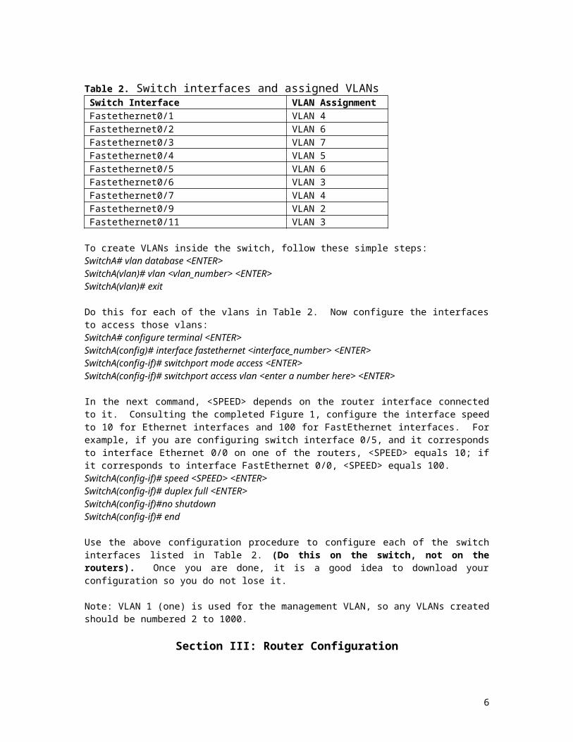
Table 2 lists the different switch interfaces we will be using, along with their respective VLAN connections. Consulting this table, label the router interfaces in Figure 1 with their respective switch interface assignments. For example, VLAN 6 is assigned across two switch interfaces, FastEthernet0/2 and FastEthernet0/5. In Figure 1, there are two router interfaces which connect to VLAN 6, so assign switch interface 0/2 to one, and switch interface 0/5 to the other.
Table 2. Switch interfaces and assigned VLANsSwitch Interface VLAN AssignmentFastethernet0/1 VLAN 4Fastethernet0/2 VLAN 6Fastethernet0/3 VLAN 7Fastethernet0/4 VLAN 5Fastethernet0/5 VLAN 6Fastethernet0/6 VLAN 3Fastethernet0/7 VLAN 4Fastethernet0/9 VLAN 2Fastethernet0/11 VLAN 3
To create VLANs inside the switch, follow these simple steps:SwitchA# vlan database <ENTER>SwitchA(vlan)# vlan <vlan_number> <ENTER>SwitchA(vlan)# exit
Do this for each of the vlans in Table 2. Now configure the interfaces to access those vlans:SwitchA# configure terminal <ENTER>SwitchA(config)# interface fastethernet <interface_number> <ENTER>SwitchA(config-if)# switchport mode access <ENTER>SwitchA(config-if)# switchport access vlan <enter a number here> <ENTER>
In the next command, <SPEED> depends on the router interface connected to it. Consulting the completed Figure 1, configure the interface speed to 10 for Ethernet interfaces and 100 for FastEthernet interfaces. For example, if you are configuring switch interface 0/5, and it corresponds to interface Ethernet 0/0 on one of the routers, <SPEED> equals 10; if it corresponds to interface FastEthernet 0/0, <SPEED> equals 100.SwitchA(config-if)# speed <SPEED> <ENTER>SwitchA(config-if)# duplex full <ENTER>SwitchA(config-if)#no shutdownSwitchA(config-if)# end
Use the above configuration procedure to configure each of the switch interfaces listed in Table 2. (Do this on the switch, not on the routers). Once you are done, it is a good idea to download your configuration so you do not lose it.
Note: VLAN 1 (one) is used for the management VLAN, so any VLANs created should be numbered 2 to 1000.
4
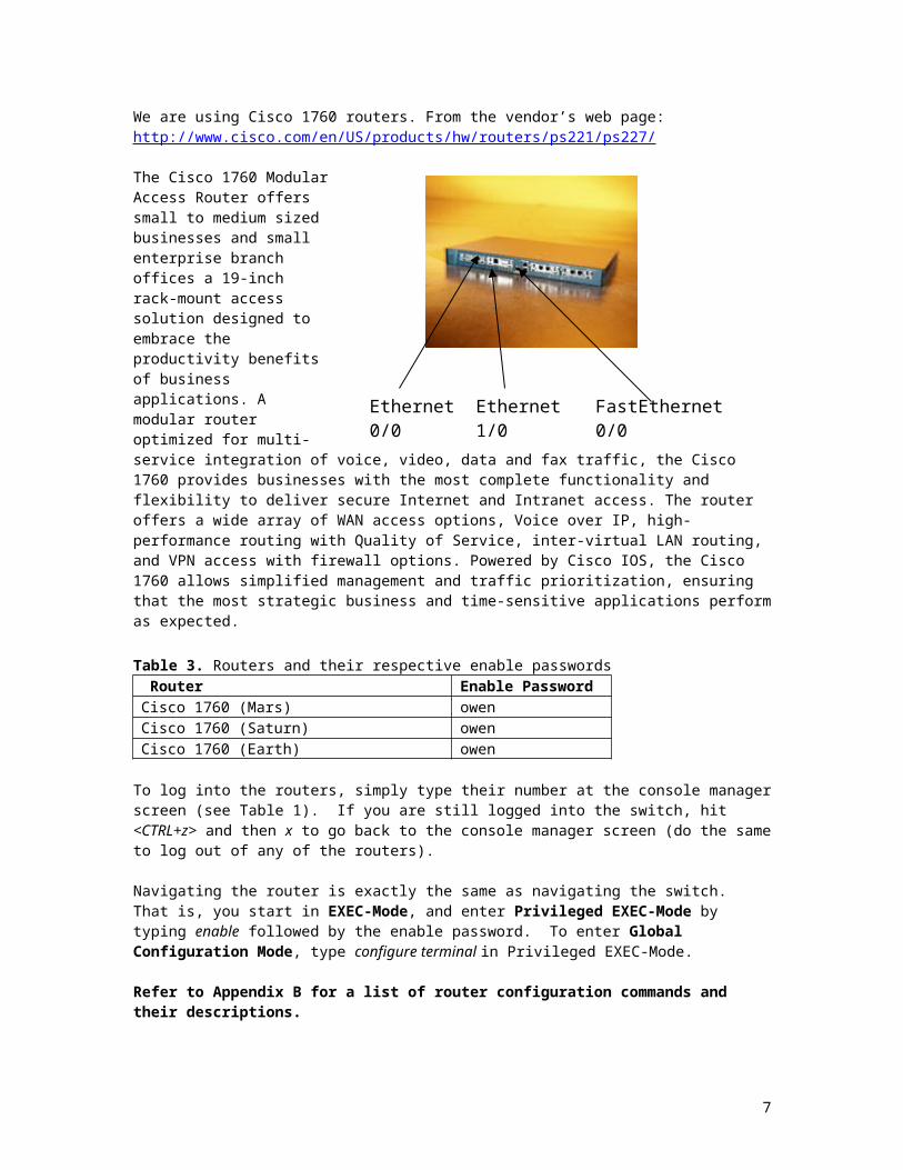
Ethernet 0/0 Ethernet 1/0 FastEthernet 0/0
Section III: Router Configuration
We are using Cisco 1760 routers. From the vendor’s web page:http://www.cisco.com/en/US/products/hw/routers/ps221/ps227/
The Cisco 1760 Modular Access Router offers small to medium sized businesses and small enterprise branch offices a 19-inch rack-mount access solution designed to embrace the productivity benefits of business applications. A modular router optimized for multi-service integration of voice, video, data and fax traffic, the Cisco 1760 provides businesses with the most complete functionality and flexibility to deliver secure Internet and Intranet access. The router offers a wide array of WAN access options, Voice over IP, high-performance routing with Quality of Service, inter-virtual LAN routing, and VPN access with firewall options. Powered by Cisco IOS, the Cisco 1760 allows simplified management and traffic prioritization, ensuring that the most strategic business and time-sensitive applications perform as expected.
Table 3. Routers and their respective enable passwords Router Enable PasswordCisco 1760 (Mars) owenCisco 1760 (Saturn) owenCisco 1760 (Earth) owen
To log into the routers, simply type their number at the console manager screen (see Table 1). If you are still logged into the switch, hit <CTRL+z> and then x to go back to the console manager screen (do the same to log out of any of the routers).
Navigating the router is exactly the same as navigating the switch. That is, you start in EXEC-Mode, and enter Privileged EXEC-Mode by typing enable followed by the enable password. To enter Global Configuration Mode, type configure terminal in Privileged EXEC-Mode.
Refer to Appendix B for a list of router configuration commands and their descriptions.
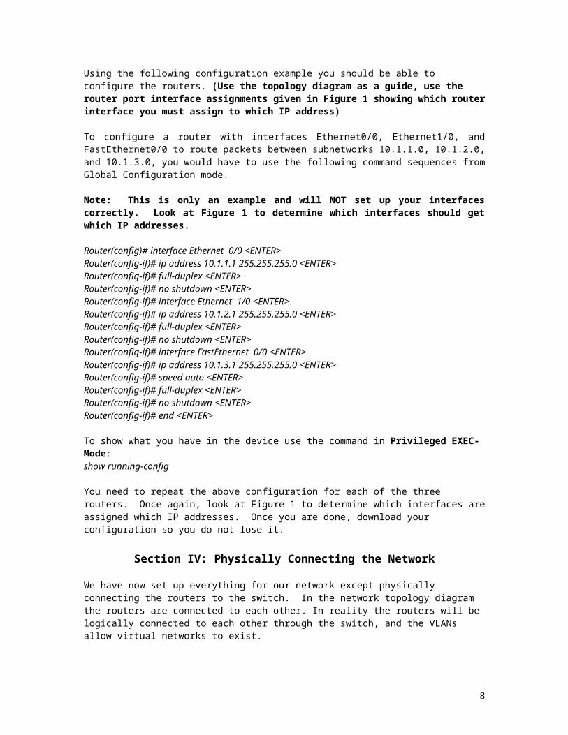
Using the following configuration example you should be able to configure the routers. (Use the topology diagram as a guide, use the router port interface assignments given in Figure 1 showing which router interface you must assign to which IP address)
To configure a router with interfaces Ethernet0/0, Ethernet1/0, and FastEthernet0/0 to route packets between subnetworks 10.1.1.0, 10.1.2.0, and 10.1.3.0, you would have to use the following command sequences from Global Configuration mode.
Note: This is only an example and will NOT set up your interfaces correctly. Look at Figure 1 to determine which interfaces should get which IP addresses.
Router(config)# interface Ethernet 0/0 <ENTER>
5
Router(config-if)# ip address 10.1.1.1 255.255.255.0 <ENTER>Router(config-if)# full-duplex <ENTER>Router(config-if)# no shutdown <ENTER>Router(config-if)# interface Ethernet 1/0 <ENTER>Router(config-if)# ip address 10.1.2.1 255.255.255.0 <ENTER>Router(config-if)# full-duplex <ENTER>Router(config-if)# no shutdown <ENTER>Router(config-if)# interface FastEthernet 0/0 <ENTER>Router(config-if)# ip address 10.1.3.1 255.255.255.0 <ENTER>Router(config-if)# speed auto <ENTER>Router(config-if)# full-duplex <ENTER>Router(config-if)# no shutdown <ENTER>Router(config-if)# end <ENTER>
To show what you have in the device use the command in Privileged EXEC-Mode:show running-config
You need to repeat the above configuration for each of the three routers. Once again, look at Figure 1 to determine which interfaces are assigned which IP addresses. Once you are done, download your configuration so you do not lose it.
Section IV: Physically Connecting the Network
We have now set up everything for our network except physically connecting the routers to the switch. In the network topology diagram the routers are connected to each other. In reality the routers will be logically connected to each other through the switch, and the VLANs allow virtual networks to exist.
Before you start, there should only be one cable connected to each piece of equipment (including equipment you are not using). The routers should only have one cable going to the Console port (the switch console ports are on the back). All other cables should be removed and stored in the box marked playstationX, where X is the number of the playstation you are using. Only use the cables located in this box to wire up your playstation, and place them back in the box when you are finished.
Consulting Figure 1, wire the three interfaces on each router to their corresponding interfaces on the switch. On each router, Ethernet 0/0 is the left interface card (labeled 10 BT ETHERNET), Ethernet 1/0 is the right interface card (labeled 10 BT ETHERNET), and FastEthernet 0/0 is the port labeled 10/100 ETHERNET. The wires should only go from the routers to the switch, i.e. no two routers should be physically connected together.
Example:
From the topology diagram, router Mars’ Ethernet 0/0 port is connected to VLAN 4 (10.1.3.0/24). When configuring the router, this port should have been assigned an IP address from VLAN4 (10.1.3.1). You should also have assigned this port a corresponding interface port on the switch (lets say FastEthernet0/1). All that remains to do is to connect the Ethernet 0/0 port on the router to the FastEthernet0/1 port (port 1) on the switch. The light for port 1 should turn orange, and after about half a minute change to green. Repeat this process for all three interfaces on all three routers. When you are done, there should be nine green lights on the switch (not counting the green light for port 24).
If the lights do not turn from orange to green after a long time, there may be a problem with the network you set up. Log into the router that is having the problem and type show running-config in Privileged EXEC-Mode to check that all three interfaces have been set up correctly.
As a second turn in figure, draw lines in figure 2 at the back of the lab handout in the turn in section to show what you physically wired to what.
6
Once all the lights are green, you should be able to have the routers ping each other; simply log into Privileged EXEC-Mode and type ping <IP>, where <IP> is the IP address of the interface you want to ping. Ping the two neighboring interfaces from each router (i.e. from Mars, ping the interfaces on Earth and Saturn connected to VLAN4 and VLAN3).
Section V: Setting Up Routing
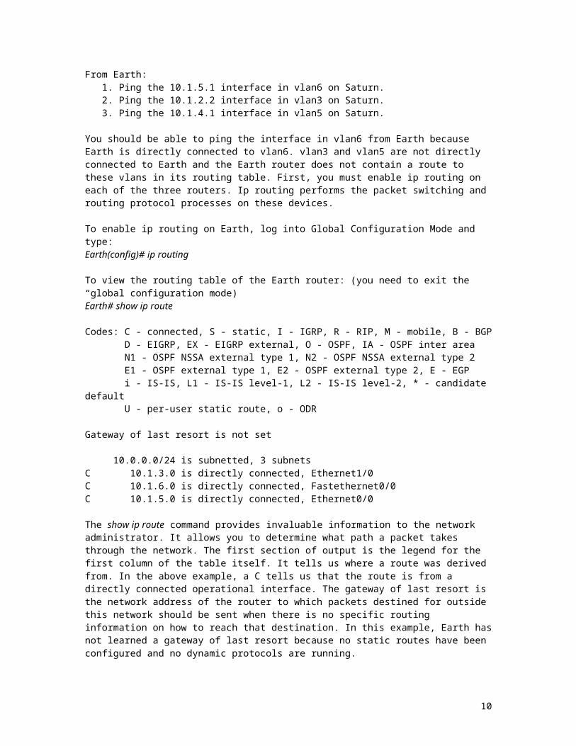
From Earth:1. Ping the 10.1.5.1 interface in vlan6 on Saturn. 2. Ping the 10.1.2.2 interface in vlan3 on Saturn.3. Ping the 10.1.4.1 interface in vlan5 on Saturn.
You should be able to ping the interface in vlan6 from Earth because Earth is directly connected to vlan6. vlan3 and vlan5 are not directly connected to Earth and the Earth router does not contain a route to these vlans in its routing table. First, you must enable ip routing on each of the three routers. Ip routing performs the packet switching and routing protocol processes on these devices.
To enable ip routing on Earth, log into Global Configuration Mode and type:Earth(config)# ip routing
To view the routing table of the Earth router: (you need to exit the “global configuration mode)Earth# show ip route
Codes: C - connected, S - static, I - IGRP, R - RIP, M - mobile, B - BGP D - EIGRP, EX - EIGRP external, O - OSPF, IA - OSPF inter area N1 - OSPF NSSA external type 1, N2 - OSPF NSSA external type 2 E1 - OSPF external type 1, E2 - OSPF external type 2, E - EGP i - IS-IS, L1 - IS-IS level-1, L2 - IS-IS level-2, * - candidate default U - per-user static route, o - ODR
Gateway of last resort is not set
10.0.0.0/24 is subnetted, 3 subnetsC 10.1.3.0 is directly connected, Ethernet1/0C 10.1.6.0 is directly connected, Fastethernet0/0C 10.1.5.0 is directly connected, Ethernet0/0
The show ip route command provides invaluable information to the network administrator. It allows you to determine what path a packet takes through the network. The first section of output is the legend for the first column of the table itself. It tells us where a route was derived from. In the above example, a C tells us that the route is from a directly connected operational interface. The gateway of last resort is the network address of the router to which packets destined for outside this network should be sent when there is no specific routing information on how to reach that destination. In this example, Earth has not learned a gateway of last resort because no static routes have been configured and no dynamic protocols are running.
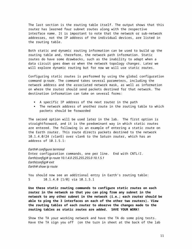
The last section is the routing table itself. The output shows that this router has learned four subnet routes along with the respective interface name. It is important to note that the network or sub-network addresses, not the IP address of the individual devices, are listed in the routing table.
Both static and dynamic routing information can be used to build up the routing table and, therefore, the network path information. Static routes do have some drawbacks, such as the inability to adapt when a data circuit goes down or when the network topology changes. Later we will explore dynamic routing but for now we will use static routes.
7
Configuring static routes is performed by using the global configuration command ip route. The command takes several parameters, including the network address and the associated network mask, as well as information on where the router should send packets destined for that network. The destination information can take on several forms:
A specific IP address of the next router in the path The network address of another route in the routing table to which packets should be forwarded
The second option will be used later in the lab. The first option is straightforward, and it is the predominant way in which static routes are entered. The following is an example of entering a static route on the Earth router. This route directs packets destined to the network 10.1.4.0/24 (vlan5) over vlan6 to the Saturn router, which has an address of 10.1.5.1:
Earth# configure terminalEnter configuration commands, one per line. End with CNTL/Z.Earth(config)# ip route 10.1.4.0 255.255.255.0 10.1.5.1Earth(config)# exitEarth# show ip route
You should now see an additional entry in Earth’s routing table:S 10.1.4.0 [1/0] via 10.1.5.1
Use these static routing commands to configure static routes on each router in the network so that you can ping from any subnet in the network to any other subnet in the network (i.e.; each router should be able to ping the 3 interfaces on each of the other two routers). View the routing tables of each router to observe the changes made to the routing tables as static routes are added. SAVE YOUR WORK!
Show the TA your working network and have the TA do some ping tests. Have the TA sign you off (on the turn in sheet at the back of the lab handout) as completing Part I. You will need to turn in the diagrams after completion of Part II.
Part 1 Check-off point: show the lab TA your working network and routing tables.
See turn in sheet at the back of this handout.
8
PART II
Section V: Setting up Sub-Interfaces
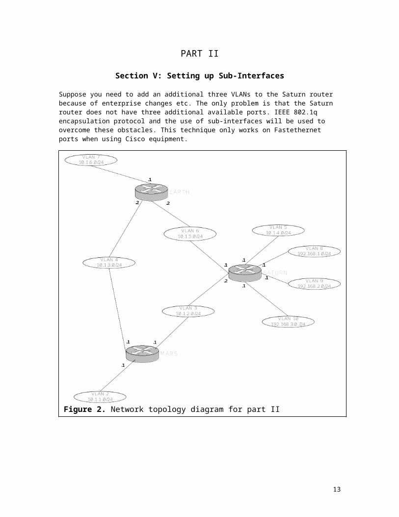
Suppose you need to add an additional three VLANs to the Saturn router because of enterprise changes etc. The only problem is that the Saturn router does not have three additional available ports. IEEE 802.1q encapsulation protocol and the use of sub-interfaces will be used to overcome these obstacles. This technique only works on Fastethernet ports when using Cisco equipment.
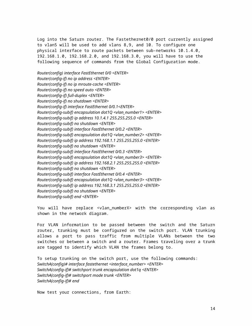
Log into the Saturn router. The Fastethernet0/0 port currently assigned to vlan5 will be used to add vlans 8,9, and 10. To configure one physical interface to route packets between sub-networks 10.1.4.0, 192.168.1.0, 192.168.2.0, and 192.168.3.0, you will have to use the following sequence of commands from the Global Configuration mode.
Router(config) interface FastEthernet 0/0 <ENTER>Router(config-if) no ip address <ENTER>Router(config-if) no ip mroute-cache <ENTER>Router(config-if) no speed auto <ENTER>Router(config-if) full-duplex <ENTER>
9
Figure 2. Network topology diagram for part II
Router(config-if) no shutdown <ENTER>Router(config-if) interface FastEthernet 0/0.1<ENTER>Router(config-subif) encapsulation dot1Q <vlan_number1> <ENTER>Router(config-subif) ip address 10.1.4.1 255.255.255.0 <ENTER>Router(config-subif) no shutdown <ENTER>Router(config-subif) interface FastEthernet 0/0.2 <ENTER>Router(config-subif) encapsulation dot1Q <vlan_number2> <ENTER>Router(config-subif) ip address 192.168.1.1 255.255.255.0 <ENTER>Router(config-subif) no shutdown <ENTER>Router(config-subif) interface FastEthernet 0/0.3 <ENTER>Router(config-subif) encapsulation dot1Q <vlan_number3> <ENTER>Router(config-subif) ip address 192.168.2.1 255.255.255.0 <ENTER>Router(config-subif) no shutdown <ENTER>Router(config-subif) interface FastEthernet 0/0.4 <ENTER>Router(config-subif) encapsulation dot1Q <vlan_number3> <ENTER>Router(config-subif) ip address 192.168.3.1 255.255.255.0 <ENTER>Router(config-subif) no shutdown <ENTER>Router(config-subif) end <ENTER>
You will have replace <vlan_numberX> with the corresponding vlan as shown in the network diagram.
For VLAN information to be passed between the switch and the Saturn router, trunking must be configured on the switch port. VLAN trunking allows a port to pass traffic from multiple VLANs between the two switches or between a switch and a router. Frames traveling over a trunk are tagged to identify which VLAN the frames belong to.
To setup trunking on the switch port, use the following commands:SwitchA(config)# interface fastethernet <interface_number> <ENTER>SwitchA(config-if)# switchport trunk encapsulation dot1q <ENTER>SwitchA(config-if)# switchport mode trunk <ENTER>SwitchA(config-if)# end
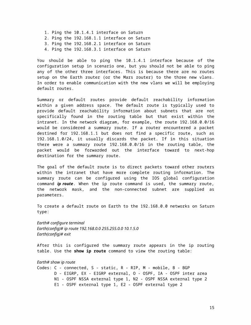
Now test your connections, from Earth:1. Ping the 10.1.4.1 interface on Saturn2. Ping the 192.168.1.1 interface on Saturn3. Ping the 192.168.2.1 interface on Saturn4. Ping the 192.168.3.1 interface on Saturn
You should be able to ping the 10.1.4.1 interface because of the configuration setup in scenario one, but you should not be able to ping any of the other three interfaces. This is because there are no routes setup on the Earth router (or the Mars router) to the three new vlans. In order to enable communication with the new vlans we will be employing default routes.
Summary or default routes provide default reachability information within a given address space. The default route is typically used to provide default reachability information about subnets that are not specifically found in the routing table but that exist within the intranet. In the network diagram, for example, the route 192.168.0.0/16 would be considered a summary route. If a router encountered a packet destined for 192.168.1.1 but does not find a specific route, such as 192.168.1.0/24, it usually discards the packet. If in this situation there were a summary route 192.168.0.0/16 in the routing table, the packet would be forwarded out the interface toward to next-hop destination for the summary route.
The goal of the default route is to direct packets toward other routers within the intranet that have more complete routing information. The summary route can be configured using the IOS global configuration command ip route. When the ip route command is used, the summary route, the network mask, and the non-connected subnet are supplied as parameters.
10
To create a default route on Earth to the 192.168.0.0 networks on Saturn type:
Earth# configure terminalEarth(config)# ip route 192.168.0.0 255.255.0.0 10.1.5.0Earth(config)# exit
After this is configured the summary route appears in the ip routing table. Use the show ip route command to view the routing table:
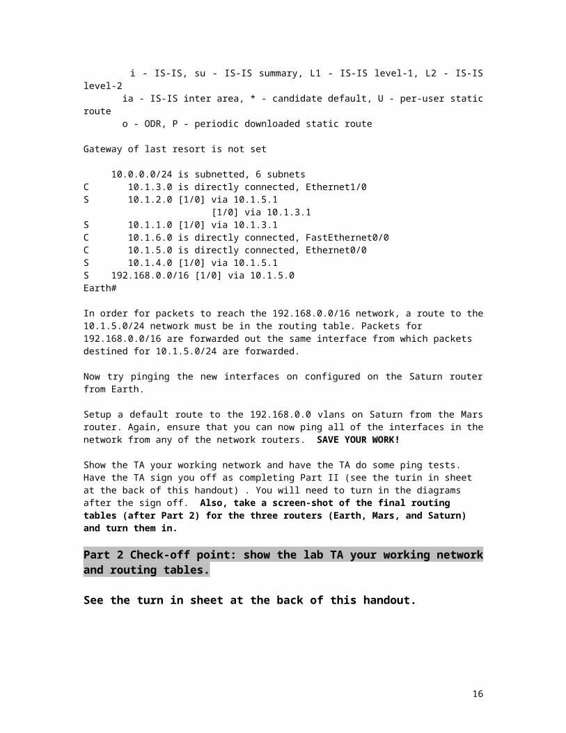
Earth# show ip routeCodes: C - connected, S - static, R - RIP, M - mobile, B - BGP D - EIGRP, EX - EIGRP external, O - OSPF, IA - OSPF inter area N1 - OSPF NSSA external type 1, N2 - OSPF NSSA external type 2 E1 - OSPF external type 1, E2 - OSPF external type 2 i - IS-IS, su - IS-IS summary, L1 - IS-IS level-1, L2 - IS-IS level-2 ia - IS-IS inter area, * - candidate default, U - per-user static route o - ODR, P - periodic downloaded static route
Gateway of last resort is not set
10.0.0.0/24 is subnetted, 6 subnetsC 10.1.3.0 is directly connected, Ethernet1/0S 10.1.2.0 [1/0] via 10.1.5.1 [1/0] via 10.1.3.1S 10.1.1.0 [1/0] via 10.1.3.1C 10.1.6.0 is directly connected, FastEthernet0/0C 10.1.5.0 is directly connected, Ethernet0/0S 10.1.4.0 [1/0] via 10.1.5.1S 192.168.0.0/16 [1/0] via 10.1.5.0Earth#
In order for packets to reach the 192.168.0.0/16 network, a route to the 10.1.5.0/24 network must be in the routing table. Packets for 192.168.0.0/16 are forwarded out the same interface from which packets destined for 10.1.5.0/24 are forwarded.
Now try pinging the new interfaces on configured on the Saturn router from Earth.
Setup a default route to the 192.168.0.0 vlans on Saturn from the Mars router. Again, ensure that you can now ping all of the interfaces in the network from any of the network routers. SAVE YOUR WORK! Show the TA your working network and have the TA do some ping tests. Have the TA sign you off as completing Part II (see the turin in sheet at the back of this handout) . You will need to turn in the diagrams after the sign off. Also, take a screen-shot of the final routing tables (after Part 2) for the three routers (Earth, Mars, and Saturn) and turn them in.
Part 2 Check-off point: show the lab TA your working network and routing tables.
See the turn in sheet at the back of this handout.
11

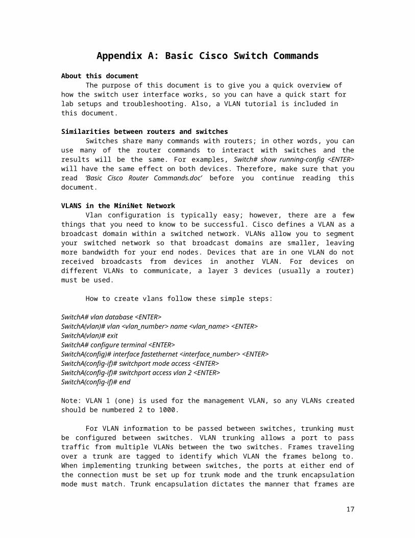
Appendix A: Basic Cisco Switch Commands
About this documentThe purpose of this document is to give you a quick overview of how the switch user interface
works, so you can have a quick start for lab setups and troubleshooting. Also, a VLAN tutorial is included in this document.
Similarities between routers and switchesSwitches share many commands with routers; in other words, you can use many of the router
commands to interact with switches and the results will be the same. For examples, Switch# show running-config <ENTER> will have the same effect on both devices. Therefore, make sure that you read ‘Basic Cisco Router Commands.doc’ before you continue reading this document.
VLANS in the MiniNet NetworkVlan configuration is typically easy; however, there are a few things that you need to know to be
successful. Cisco defines a VLAN as a broadcast domain within a switched network. VLANs allow you to segment your switched network so that broadcast domains are smaller, leaving more bandwidth for your end nodes. Devices that are in one VLAN do not received broadcasts from devices in another VLAN. For devices on different VLANs to communicate, a layer 3 devices (usually a router) must be used.
How to create vlans follow these simple steps:
SwitchA# vlan database <ENTER>SwitchA(vlan)# vlan <vlan_number> name <vlan_name> <ENTER>SwitchA(vlan)# exitSwitchA# configure terminal <ENTER>SwitchA(config)# interface fastethernet <interface_number> <ENTER>SwitchA(config-if)# switchport mode access <ENTER>SwitchA(config-if)# switchport access vlan 2 <ENTER>SwitchA(config-if)# end
Note: VLAN 1 (one) is used for the management VLAN, so any VLANs created should be numbered 2 to 1000.
For VLAN information to be passed between switches, trunking must be configured between switches. VLAN trunking allows a port to pass traffic from multiple VLANs between the two switches. Frames traveling over a trunk are tagged to identify which VLAN the frames belong to. When implementing trunking between switches, the ports at either end of the connection must be set up for trunk mode and the trunk encapsulation mode must match. Trunk encapsulation dictates the manner that frames are identified (tagged) on a trunk and defines the VLAN services available. There are four types of trunking encapsulations: 1) Inter-Switch Link Protocol (ISL) Cisco proprietary trunking protocol; 2) IEEE 802.1Q (dot1q) Industry standard trunking protocol; 3) LAN Emulation (LANE) Used for trunking VLANs over ATM links; and 4) IEEE 802.10 (dot10q) Cisco proprietary method for transporting VLAN information inside standard FDDI frames.
To setup trunking between two switches, use the following commands:SwitchA(config)# interface fastethernet <interface_number> <ENTER>SwitchA(config-if)# switchport mode trunk <ENTER>SwitchA(config-if)# switchport trunk encapsulation dot1q <ENTER>SwitchA(config-if)# end
Then, go to the other switch, and repeat these commands on the respective interface. This is important, otherwise, both switches will not be able to communicate to each other.
To limit which VLANs will be allowed to pass information on the port you can use the following commands:
12
SwitchA(config)# interface fastethernet <interface_number> <ENTER>SwitchA(config-if)# switchport trunk allowed vlan remove 1-1005 <ENTER>SwitchA(config-if)# switchport trunk allowed vlan add 1-3 <ENTER>
Then, you will have to repeat these commands on the other switch.
The previous commands remove the default of all VLANs, and adds back support for VLANs 1-3.
Finally, to avoid having to reconfigure your VLANs in case the switches are rebooted, type the following:
RouterA# copy running-config startup-config <ENTER>
13
Appendix B: Basic Cisco Router Commands
References on the www and hardcopyhttp://www.cisco.com/univercd/cc/td/doc/product/software/ios120/12cgcr/rbkixol.htmCisco Router Configuration, 2nd Edition, A practical Introduction to Cisco IOS Software configuration.
About this documentThe purpose of this document is to give you a quick overview of how the router interface works,
so you can have a quick start for lab setups and troubleshooting.
Configuring a Router from Scratch
If the router is turned on for the first time or if the router has a missing startup-config file, then, you will see a message that says:Would you like to enter the initial configuration dialog? [yes/no]:At this message just type no and press the <ENTER> key.You will see the router prompt as ‘Router>’. This means that the default running configuration was loaded; in other words, the router is not configured. To configure it, you will have to type ‘enable’ followed by pressing the ‘<ENTER>’ key. It will not ask you for a password since it has not been set up since starting from scratch. Now you will see the router prompt as ‘Router#’.
Editing CommandsThe following command or key-strokes are used to move around the command
line inside the router.Command Description
<CTRL>+A Moves to the beginning of the command line<ESC>+B Moves back one word<CTRL>+B orLeft Arrow key
Moves back one character
<CTRL>+E Moves to the end of the command line<CTRL>+F orRight Arrow key
Moves forward one character
<ESC>+F Moves forward one word<CTRL>+k Deletes all characters from the cursor until the end of the line<CTRL>+p or Up Arrow key
Recalls last (previous) command
<CTRL>+n orDown Arrow key
Recalls most recent command
>show history or#show history
Shows command buffer
<TAB> Command completion – completes a partial command name? Displays all available commands or command parameters
Three command modes used in routers are EXEC-Mode, Privileged EXEC-Mode, and Global Configuration Mode. There other command modes, but these are the main ones.
EXEC-Mode CommandsProvides a limited subset of commands. The first time you connect to a router, this is the mode
that you will be in. The command prompt has the form ‘Router>’To get a list of commands type ‘?’. If you see --More--, that means that the screen can be advanced by pressing either <ENTER> key, scrolls one line up, or <SPACE>, scrolls one page up.
14
Privileged EXEC-Mode CommandsProvides access to all commands in the router. To enter Privileged EXEC-Mode from EXEC-
Mode, type enable<ENTER>. If a password has been setup for Privileged EXEC-Mode, you will be asked for it. It is assumed that the router has been reset to its default settings, and that it does not have any passwords setup.Some of the commands that you will need to use are shown in the following table.
Command Descriptionconfigure terminal Enters Global Configuration Mode.copy Copies configuration or image datacopy running-config startup-config Stores the current configuration in RAM into NVRAMcopy running-config <file_name> Copies the current configuration in RAM into <file_name>
located in flash: devicedir [device] List the files on a given device, use dir ? for a list of possible
parameters for devicedisable Turns off privileged commands enable password Sets a local password to control access to various privileged
levelsenable secret Specifies an additional layer or security over the enable
password commanderase startup-config Erases the content of NVRAMerase Erases Flash or configuration memoryexit Exits any configuration mode, or closes an active terminal
session and terminates the EXECreload Halts and performs a cold return; reloads the operating
system. It will also reload the startup-config file if available.ping Sends an echo request; diagnoses basic network connectivityshow [options] This is a very important command since you can display a
great variety of router information. Type ‘show ?’ to display all your possible options.
show running-config Displays the current configuration in RAMshow interfaces Displays statistics for all interfaces configured on the routershow ip interface Displays the status and global parameters associated with an
interfaceshow ip protocols Displays the parameters and current state of the active
routing protocol processshow startup-config Displays the saved configuration, which is the contents of
NVRAMmore Displays the contents of a filesetup Enters the setup command facility? Displays all available commands or command parameters
Global Configuration ModeThis mode allows you to make changes to the running configuration. You will need to know more
about this mode that anything else. From here you can configure routing protocols, interfaces, sub-interfaces, and more. To enter Global Configuration Mode, you will need to be in Privileged ECEX-Mode. Then, type ‘configure terminal <ENTER>’.
From this mode, you can have access to two sub-modes: the Interface Configuration mode and the Sub-interface Configuration mode. To enter either of these modes, you will need to type the interface command followed by a interface or a subinterface.
Notice that some routers have three physical interface, but other routers have only one physical interface. In the case of routers with only one interface, subinterfaces are created on top of the physical interface(more details on this are given later on). In addition, interfaces are named as either EthernetX/Y or FastEthernetX/Y where X will normally take numbers between 0-1, and Y will normally take values like 0,1,2,3,0.1,0.2, or 0.3 (the values for X and Y given here apply to our lab setup only; they could be
15
different in other network setups). Also, routers have a mixture of Ethernet and FastEthernet interfaces whereas switches (in our lab network) have FastEthernet interfaces. Take a look at the ‘ece4110-2004-02-Fall-labs-7-and-8-LabSetup.xls’ file to get familiar with the router interface names.
The following table shows some commands and subcommands that you can use in Global Configuration mode.
Command Descriptioninterface Configures an interface type and enters configuration mode.ip address Assigns and address and a subnet mask and starts IP processing on an interfaceip default-network Establishes a default routeip host Makes a static name-to-address entry in the router’s configuration fileip route Establishes static routesline Identifies a specific line for configuration and starts the line configuration
command collection mode.login Logs in as a particular user. Enables password checking at loginnetwork Assigns a Network Information Center-based address to which the router is
directly connected.no shutdown Restarts a disabled interfacerouter Starts a routing process by first defining an IP routing protocol. For example,
router rip selects RIP as the routing protocolencapsulation Set encapsulation type for an interface This is used to attach a sub-interface to a
specific vlan.full-duplex Configure full-duplex operational modehalf-duplex Configure half-duplex and related commands? Displays all available commands or command parameters
Configuration ExamplesTo configure router with interfaces Ethernet0, Ethernet1, and FastEthernet0 to route packes
between subnetworks 10.1.1.0, 10.1.2.0, and 10.1.3.0, you will have to use the following command sequences from Global Configuration mode.
Router(config)# interface Ethernet0 <ENTER>Router(config-if)#ip address 10.1.1.1 255.255.255.0 <ENTER>Router(config-if)full-duplex <ENTER>Router(config-if) no shutdown <ENTER># It is optional to type exit after you have configured one interface and before # configuring the next oneRouter(config-if)interface Ethernet1 <ENTER>Router(config-if)ip address 10.1.2.1 255.255.255.0 <ENTER>Router(config-if)full-duplex <ENTER>Router(config-if) no shutdown <ENTER>Router(config-if)interface FastEthernet0 <ENTER>Router(config-if)ip address 10.1.3.1 255.255.255.0 <ENTER>Router(config-if)speed auto <ENTER>Router(config-if)full-duplex <ENTER>Router(config-if) no shutdown <ENTER>Router(config-if) end <ENTER>
To configure a router with interfaces Ethernet0/0, Ethernet1/0, and FastEthernet0/0 to route packes between subnetworks 10.1.1.0, 10.1.2.0, and 10.1.3.0, you will have to replace the respective interface names on the command lines shown above.
To configure a router with interface with only one physical interface FastEthernet0/0 to route packets between subnetworks 10.1.1.0, 10.1.2.0, and 10.1.3.0, you will have to use the following command sequences from Global Configuration mode.
16
Router(config)interface FastEthernet0/0 <ENTER>Router(config-if)no ip address <ENTER>Router(config-if)no ip mroute-cache <ENTER>Router(config-if)speed auto <ENTER>Router(config-if)full-duplex <ENTER>Router(config-if) no shutdown <ENTER>Router(config-if)interface FastEthernet0/0.1<ENTER>Router(config-if)encapsulation dot1Q <vlan_number1> <ENTER>Router(config-if)ip address 10.1.1.1 255.255.255.0 <ENTER>Router(config-if) no shutdown <ENTER>Router(config-if)interface FastEthernet0/0.2 <ENTER>Router(config-if)encapsulation dot1Q <vlan_number2> <ENTER>Router(config-if)ip address 10.1.2.1 255.255.255.0 <ENTER>Router(config-if) no shutdown <ENTER>Router(config-if)interface FastEthernet0/0.3 <ENTER>Router(config-if)encapsulation dot1Q <vlan_number3> <ENTER>Router(config-if)ip address 10.1.3.1 255.255.255.0 <ENTER>Router(config-if) no shutdown <ENTER>Router(config-if) end <ENTER>
# you will have to replace <vlan_numberX> with the corresponding VLAN
17
Appendix C: Saving and restoring your configurations
The scripts for uploading and downloading configurations are located on the NAS in the Lab6 directory. They are in a tarball named mnet_tools_v1.5.tar. Copy this file to your /root directory, and unpack it using:# tar –xf mnet_tools_v1.5.tar# cd mnet_tools_v1.5
Before these scripts will work, the following two perl modules must be installed:
IO-Tty-1.02.tar.gz Expect-1.15.tar.gz
Here's how to install the modules:
First install IO-Tty-1.02.tar.gz# tar -zxvf IO-Tty-1.02.tar.gz# cd IO-Tty-1.02# perl Makefile.PL# make# make install
Then install Expect-1.15.tar.gz# tar -zxvf Expect-1.15.tar.gz# cd Expect-1.15# perl Makefile.PL# make# make install
Now you can run minictrl.pl to make sure it is working correctly. The program should output it's usage and exit.# ./minictrl.pl
Now, some notes on the actual scripts:Extension "p1", "p2", and "p3" on scripts below refer to playstation #1, playstation #2, and playstation #3 respectively. Each group of files is described below.
Download and upload of configurations is based on a perl Expect module. The nature of this module is complex and finicky. Therefore, sometimes it is necessary to run an upload or download script multiple times in order to successfully upload or download. Currently, three tries are given for each upload and download. Therefore, you may see errors in the download or upload process. However, at the end of the script, you should see a successful message printed indicating that one of the three tries was successful. Run the scripts using:#./<script_name>in the directory the script is located. The scripts are described below.
download_reset_p1download_reset_p2download_reset_p3These scripts are used to download reset configuations. The network devices should be configured to their reset configuation before running these scripts. Then, these scripts can be executed to store a "reset" configuration. YOU NEVER NEED TO RUN THIS SCRIPT. The reset configurations are included in the tarball: reset1, reset2, and reset3.
reset_p1reset_p2
18
reset_p3These scripts return the playstations to a "reset" configuration, which must be downloaded using the download_reset scripts above first.
download_p1download_p2download_p3These scripts are used to download all network device configurations for the devices in the give playstation. The configurations are stored in files in a subfolder called playstation1, playstation2, and playstation3 respectively. Download time can vary from 30-60 seconds
upload_p1upload_p2upload_p3These scripts are used to restore device configurations. They can only be executed after succesfully downloading configurations using the download scripts. Upload time can vary from 3-5 minutes because the network devices must be reloaded, which takes several minutes.
CM_Library.pmLibrary used by minictrl to download, upload, and connect to digi.
minictrl.plTool that does the downloading and uploading of configurations.
single_cmdInternal wrapper tool.
19
ECE 4110 Internetwork ProgrammingTurn in sheet
Lab 6: Setting up a Network Using Cisco Routers, Switched and VLAN Technology
Group Number: ________
Member Names: _________________________ _________________________
Date: _____________________
Part 1 Check-off point: show the lab TA your working network and routing tables.
TA Signature _______________________ DATE ______________________
Part 2 Check-off point: show the lab TA your working network and routing tables.
TA Signature _______________________ DATE ______________________
Turn-in List
1. The turn in sheet from the back of the lab2. Figure 1: Completed Network Topology3. Figure 2: Physical Cabling Diagram4. Three Screenshots: Routing tables for the three routers
20
PLAYSTATION #: ________________
21
Figure 1. Network topology diagram
ethernet 1/0 ethernet 0/0
Fastethernet 0/0switch _/_
switch _/_switch _/_
ethernet 1/0
Ethernet 0/0
Fastethernet 0/0
switch _/_
switch _/_
Fastethernet 0/0
ethernet 1/0
switch _/_
switch _/_Digi # _____
Digi # _____
Digi # ____
ethernet 0/0
switch _/_ switch _/_
The switch is Digi # _____
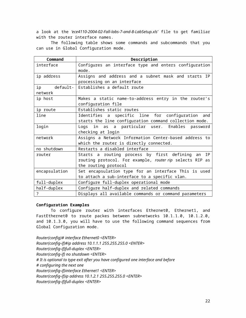
Figure 2. Physical cabling diagram.
22
Ethernet 0/1 Ethernet 0/0 Ethernet 0/1
Fast Ethernet 0/0
Ethernet 0/1 Ethernet 0/0 Ethernet 1/0
Fast Ethernet 0/0
Ethernet 0/1 Ethernet 0/0 Ethernet 1/0
Fast Ethernet 0/0
Ethernet 0/1 Ethernet 0/0 Ethernet 1/0
Fast Ethernet 0/0Earth digi # ___
Saturn digi # ___
Mars digi # ___
Switch digi # ___