COLUMBUS, INDIANA: EERO SAARINEN’S LEGACY A THESIS SUBMITTED TO
This may be the author’s version of a work that was submitted/acceptedfor publication in the following source:
Poologanathan, Keerthan & Mahendran, Mahen(2012)Shear behaviour and strength of LiteSteel beams with web openings.Advances in Structural Engineering, 15(2), pp. 171-184.
This file was downloaded from: https://eprints.qut.edu.au/48919/
c© Consult author(s) regarding copyright matters
This work is covered by copyright. Unless the document is being made available under aCreative Commons Licence, you must assume that re-use is limited to personal use andthat permission from the copyright owner must be obtained for all other uses. If the docu-ment is available under a Creative Commons License (or other specified license) then referto the Licence for details of permitted re-use. It is a condition of access that users recog-nise and abide by the legal requirements associated with these rights. If you believe thatthis work infringes copyright please provide details by email to [email protected]
Notice: Please note that this document may not be the Version of Record(i.e. published version) of the work. Author manuscript versions (as Sub-mitted for peer review or as Accepted for publication after peer review) canbe identified by an absence of publisher branding and/or typeset appear-ance. If there is any doubt, please refer to the published source.
https://doi.org/10.1260/1369-4332.15.2.171
Shear Behaviour and Strength of LiteSteel Beams with Web
Openings
Poologanathan Keerthan and Mahen Mahendran
Faculty of Built Environment and Engineering
Queensland University of Technology, Brisbane, QLD 4000, Australia
Abstract: The LiteSteel Beam (LSB) is a new cold-formed steel hollow flange
channel beam recently developed in Australia. It is commonly used as a floor joist or
bearer in buildings. Current practice in flooring systems is to include openings in the
web element of floor joists or bearers so that building services can be located within
them. Shear behaviour of LSBs with web openings is more complicated while their
shear strengths are considerably reduced by the presence of web openings. However,
no research has been undertaken on the shear behaviour and strength of LSBs with
web openings. Therefore a detailed experimental study involving 26 shear tests was
undertaken on simply supported LSB test specimens with web openings and an
aspect ratio of 1.5. This paper presents the details of this experimental study and the
results of their shear capacities and behavioural characteristics. Experimental results
showed that the current design rules in cold-formed steel structures design codes are
very conservative for the shear design of LSBs with web openings. Improved design
equations have been proposed for the shear strength of LSBs with web openings
based on the experimental results from this study.
Keywords: LiteSteel beam, Shear strength, Cold-formed steel structures, Web
openings, Slender web and Hollow flanges.
Corresponding Author’s Email address, Phone and Fax Numbers:
Email: [email protected]
Phone: 61 7 3138 2543
Fax: 61 3138 1170
1. Introduction
The use of cold-formed steel members in building construction has increased significantly in
recent times. There are many benefits associated with the use of lightweight cold-formed steel
sections in residential, industrial and commercial buildings. Thinner cold-formed steel
sections with varying geometry are continuously developed to suit changing requirements
including higher flexural capacities. LiteSteel Beam (LSB) is a new cold-formed steel hollow
flange channel beam produced by OneSteel Australian Tube Mills (LST, 2009). It is
manufactured from a single strip of high strength steel through the use of a combined cold-
forming and dual electric resistance welding process. The effective distribution of steel in
LSBs with two rectangular hollow flanges results in a thin and lightweight section with good
flexural capacity (Figure 1(a)). The LSB has many applications but, in particular, has become
a very popular choice in the flooring systems as shown in Figure 1(b) (LST, 2009). Table 1
provides the currently available LSB sections and their dimensions.
Current practice in flooring systems is to include openings in the web of floor joists or bearers
so that building services can be located within them. Without web openings, services have to
be located under the joists leading to increased floor height. This is not an effective use of
space and an undesirable result for users. Pokharel and Mahendran (2006) recommended the
use of circular web openings in LSBs based on an investigation using finite element analyses.
Figure 2 shows an LSB joist with circular web openings. Three standard opening sizes of 60,
102 and 127 mm are used with currently available LSBs (OATM, 2008).
The use of web openings in a beam section significantly reduces its shear capacity due to the
reduced web area. The shear flow in 125x45x2.0 LSB shown in Figure 3 demonstrates that
approximately 88% of the shear force is supported by the main web element of LSB. The
reduction in the primary shear resisting area will lead to a significant reduction in shear
capacity of LSBs. However, the effect of web openings on the flexural capacity is negligible
as the web openings are normally located at the centre of web.
There are many variables that affect the shear capacity of members containing web openings.
They include the shape, size and location of web openings and also the slenderness of the web
element. The main aim of this research is to investigate the effect of circular web openings of
varying diameters on the shear capacities of LSB sections using a detailed experimental study.

This paper presents the details of a series of shear tests of LSBs with circular web openings,
and the results. Experimental shear capacities are compared with the predicted shear
capacities using the current design rules in Australian/New Zealand Standards AS/NZS 4600
(SA, 2005) and the North American Specification (AISI, 2007). This paper also includes a
brief review into the shear capacities of steel beams with web openings, and available shear
design rules.
2. Review of Shear Capacities of Steel Beams with Web Openings
2.1. Overview
Research into the effects of web openings on the shear capacity of steel beams was conducted
first in the early 1960s. However, most of the researches undertaken before the 1970s
concentrated primarily on the effect of openings in moderately thick elements (Hoglund,
1971). The investigation of cold-formed steel sections containing web openings was
undertaken in the last decade (Baranda et al., 1978). However, only limited research has been
undertaken on the effect of web openings in relation to LSBs. Design capacity tables
produced by OATM do not consider the shear capacity of LSBs containing web openings
(OATM, 2008).
Hoglund (1971) researched the effects of rectangular and circular holes on the shear
performance of plate girders with thin webs subject to static loading. He found that when
holes were placed in the areas of high shear force, the reduction in shear capacity was high.
Baranda et al., 1978) stated that the flexural capacity of sections with web openings was
reduced by approximately 2 to 5%. The minimal reduction in flexural capacity is a result of
the section mid-depth being a region of reduced bending stresses. Redwood and Shrivastava
(1980) stated that openings less than 30% of the section height will not cause a significant
reduction to the flexural capacity.
Narayanan (1982) tested 20 thin web plate girders containing centrally located perforations,
which were subject to shear loading. It was found that their shear capacity was reduced
linearly with increasing depth of web opening. If the depth of web opening covers the full
web depth, then the failure is caused by the Vierendeel mechanism with hinges formed
centrally at the top and bottom of the flanges.
Shan et al. (1997) conducted detailed experimental studies into the shear capacity of thin
cold-formed steel sections. They recommended that the nominal shear capacity of cold-
formed lipped channel beams with web openings can be calculated using a reduction factor
applied to the solid web strength of the shear element. Eiler (1997) extended Shan et al.’s
(1997) work to include the behaviour of web elements with openings subjected to linearly
varying shear force. Based on 85 tests of beam type members, Eiler (1997) proposed suitable
design equations for the shear strength of cold-formed steel beams with web openings, which
are given in the following sections.
McMahon et al. (2008) conducted ten shear tests of back to back LSB sections with web
openings using a three-point loading method. Their tests included three different LSB sections
with three circular web opening sizes of 60, 102 and 127 mm. Details of their test specimens
are given in Table 2. All three sections were also tested without web openings for calibration
and comparative purposes. In order to reduce the effect of bending moment on the shear
capacity, extra plates were welded to the top and bottom flanges of the beams at the centre to
increase the bending capacity and thus avoid the bending failure at the centre. Table 2 shows
the induced shear force and moment by the ultimate load (McMahon et al., 2008). As
recommended by Shan et al. (1997), McMahon et al. (2008) also developed suitable equations
for the shear capacity reduction factor in terms of the depth of web openings (dwh), which are
given in the following sections.
Chung et al. (2001) investigated the Vierendeel action associated with web openings.
Vierendeel action is a result of four plastic hinges forming at critical locations around the web
openings. This formation results in a Vierendeel mechanism as the shear forces are transferred
laterally across the openings. This, therefore, demonstrates that the effect of Vierendeel forces
is a function of the length of openings. Chung et al. (2001) stated that when a large web
opening is present the shear capacity is significantly reduced and consequently the flange
shear capacity becomes important.
Hagen et al. (2009) showed that the reduction in shear capacity due to web openings could
depend on a range of parameters relating to the removal of material from the web. The
primary parameters that govern the shear capacity are the web slenderness (d1/tw), the opening
size (dwh/d1), the yield stress of steel fyw (specifically the ratio √fyw/E) and the spacing
between transverse web stiffeners. The secondary parameters refer to the shape, location and
spacing of openings. The tertiary parameters are related to the flange cross sectional area,
bending and torsional stiffness.
A significant effect of web openings is web crippling under loading. This research is not
concerned with web crippling and therefore experiments were conducted in such a manner to
prevent web crippling. A practical solution is to stiffen the web opening. This can be achieved
by providing steel area to the web which will increase the shear capacity. However, web
stiffening often can not be a practical solution due to the associated high cost.
2.2. Shear Capacity Equations for LSBs without Web Openings
Keerthan and Mahendran (2010) proposed new shear strength formulae (Eqs. 1 to 6) for LSBs
based on the current design equations for shear strength given in AISI (2007) using finite
element analysis and experimental results. The increased shear buckling coefficient given by
Equation 7 (kLSB) is included to allow for the additional fixity in the web-flange juncture.
Equations 1 to 3 present the proposed shear strength ( v ) equations which also include the
post-buckling strength present in LSBs. The shear capacity in kN can be obtained by
multiplying the shear strength by its web area of d1tw.
ywv for yw
LSB
w f
Ek
t
d1 (Shear yielding) (1)
iywiv 2.0 foryw
LSB
wyw
LSB
f
Ek
t
d
f
Ek508.11 (Inelastic shear buckling) (2)
for yw
LSB
w f
Ek
t
d508.11 (Elastic shear buckling) (3)
where
ywyw f6.0 (4)
w
ywLSB
i
t
d
fEk
1
6.0 (5)
eywev 2.0
(6)
For LSBs )(87.0 sssfssLSB kkkk (7)
where kss, ksf = shear buckling coefficients of plates with all four edges simply supported, and
two opposite edges simply supported and fixed, respectively.
The direct strength method provides simple design procedures for cold-formed steel members.
Proposed design equations (1 to 3) are also therefore recast in the new direct strength method
format and are given as Equations 8 to 10 (AISI, 2006).
1yw
v
≤ 0.815 (8)
815.0
12.0815.0
yw
v 0.815< ≤ 1.23 (9)
22
112.0
1
yw
v > 1.23 (10)
where
ywyw f6.0 (11)
2
12
2
112
d
tEk wLSBcr
(12)
LSB
yw
wcr
yw
Ek
f
t
d1815.0
(13)
A capacity reduction factor of 0.95 is recommended in the calculation of design shear
capacities of LSBs without web openings from the above equations (AISI, 2007).
2
1
905.0
w
LSBe
t
d
Ek
2.3. Shear Capacity Reduction Factor for Cold-formed Steel Members with Web Openings
Shan et al. (1997) recommended that the nominal shear capacity of cold-formed lipped
channel beams with web openings (Vnl) can be calculated using a reduction factor qs applied
to the solid web strength of the shear element (Vv) (Eq. 14). The nominal shear capacity of
lipped channel beams with web openings is defined as follows. Equations 15 and 16 are based
on a linear relationship whereas Equation 17 is a non-linear strength reduction relationship.
(14)
71.166.31
d
dq wh
s for 38.01
d
dwh (15)
46.038.01
d
dq wh
s for 0.138.01
d
dwh (16)
)/(33.1 11051.1 dds
whq for 0.101
d
dwh and 1sq (17)
where whd is the depth of web openings, 1d is the depth of the flat portion of web and Vv is the
nominal shear strength of the solid web element. Their research included non-circular web
openings and the developed equations are considered applicable to both circular and non-
circular web openings.
McMahon et al. (2008) recommended that the shear capacity of LSBs with web openings can
be calculated using a reduction factor (qs) applied to the solid web strength of the shear
element. The reduction factor is defined as follows based on a simple linear relationship.
121
d
dq wh
s for 8.04.01
d
dwh (18)
where
1d = depth of the flat portion of web
The shear capacity reduction factor is a function of many parameters. It includes the type of
applied stress, the shape, size, location and the number of openings. Using the relevant
parameters in a dimensionless format, a general method is recommended in AS/NZS 4600
nl s vV q V
(SA, 2005). The main parameter is the ratio of the depth of web opening to the clear height of
web, dwh / d1.
AS/NZS 4600 (SA, 2005) and NAS (AISI, 2007) require that there is a minimum clear
distance of 450 mm between web openings. The ratio of the depth of web opening to the
thickness must also be less than or equal to 200, i.e. dwh /tw ≤ 200. AS/NZS 4600 restricts the
ratio of depth of web openings to flat portion of clear height of web (dwh/d1) to a value of 0.7.
The web openings are considered to be centred at mid-depth of the web. Circular hole
diameters should be less than or equal to 150 mm. AS/NZS 4600 and NAS design equations
for the shear capacity reduction factor (qs) are given next. Unlike in Shan et al. (1997),
different equations are given for circular and non-circular web openings.
1sq 54t
c (19)
t
cqs 54
545 t
c (20)
83.221 whdd
c for circular web openings (21)
221 whdd
c for non-circular web openings (22)
7.01
d
dwh 200w
wh
t
d 150 d mm
where
do = outside diameter of circular web openings
whd = depth of web openings
1d = depth of the flat portion of web
2.4. Guidelines for LSBs with Web Openings
OneSteel Australian Tube Mills (2008) provides the maximum allowable dimensions and
minimum spacing requirements for the web openings in LSB floor systems. They are used for
the web openings greater than 15 mm in diameter, where services are required to pass
through, and must be centred at the mid-height of web. Table 3 gives the allowable
dimensions of these parameters.
3. Shear Tests of LSBs with Web Openings
It is vital that key parameters are chosen carefully in the design of a test program. In order to
fully understand the shear behaviour of LSB sections with web openings several important
issues were considered when deciding these parameters such as the ratios of the depth of web
openings to clear height of web (dwh/d1) and the depth of web openings to thickness of web
(dwh/tw). Test specimens of LSBs were designed to fail in shear prior to reaching other section
capacities.
3.1. Test Specimens and Test Set-up
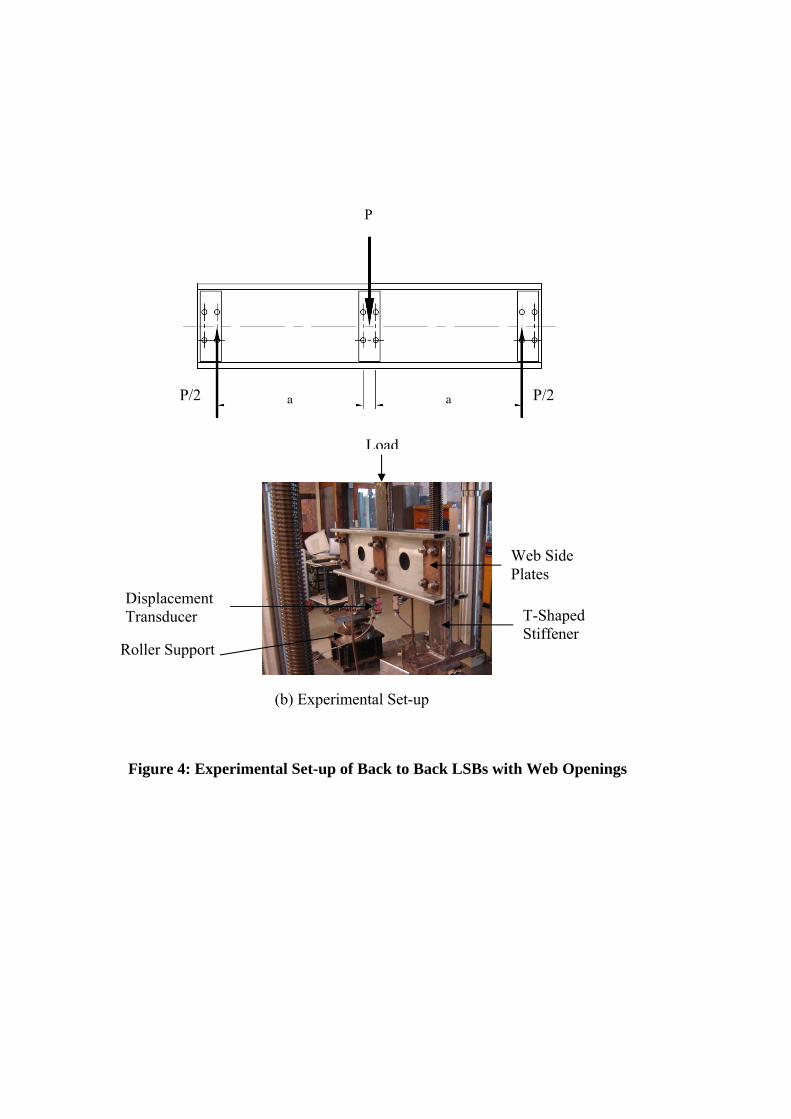
Experimental studies were carried out to investigate the shear behaviour of LSBs with web
openings using a series of primarily shear tests of simply supported LSBs subjected to a mid-
span load (see Figure 4). Two LSB sections were bolted back to back using three T-shaped
stiffeners and three web side plates located at the end supports and the loading point in order
to eliminate any torsional loading of test beams and possible web crippling of flanges and
flange bearing failures. A 30 mm gap was included between the two LSB sections (see Figure
4) to allow the test beams to behave independently while remaining together to resist torsional
effects. In order to simulate a primarily shear condition, relatively short test beams were
selected based on an aspect ratio (shear span a/ clear web height d1) of 1.5. Three opening
sizes of 60, 102 and 127 mm were chosen based on the standard sizes given in OATM (2008)
for seven of LSB sections, giving a total of 26 shear tests. Table 4 presents the details of the
shear test specimens. It includes the measured thicknesses and yield stresses of the web
elements of tested LSBs.
For LSBs d1 is defined as the clear height of web instead of the depth of the flat portion of
web measured along the plane of the web as defined in AS/NZS 4600 for cold-formed
channel sections. The reasons for this are as follows.
LSB has two rectangular hollow flanges, which are likely to increase the shear yield
capacity by framing action.
Outside of the corners are filled with weld material unlike in cold-formed channel
sections.
Buckling occurs within the clear height of web.
Although the use of d1 as the depth of the flat portion of web is conservative in
estimating the shear yield capacity, it is not safe in the case of elastic buckling.
Shear behaviour of LSBs is very similar to that of plate girders (web-flange boundary
condition and welding process), for which, clear web height is used in shear capacity
calculations.
The LSB sections were loaded through the central T-shaped stiffener that was attached to the
back to back test beam and the two web side plates with 4 M16 bolts at the mid-span loading
point. These T-shaped stiffeners were important as they avoided bearing failure of the flanges.
This method of loading has the added advantage of loading through the shear centre thus
avoiding eccentric loading and web crippling. Similar T-shaped stiffeners were also located at
the supports, and were bolted to the two LSBs and the two web side plates on either side.
Figure 4 shows the experimental set-up used in the shear tests of this research.
The support system was designed to ensure that the test beam acted as a simply supported
beam with pinned supports at each end. The test beam was supported on round sections using
ball bearings. All contact surfaces within the system were machine ground and polished to a
very smooth surface. These surfaces were lubricated to aid in the sliding of the support as
shown in Figure 4. The ends of the test beams were free to rotate and it was therefore seen
that simply supported conditions were simulated accurately at the end supports.
The applied load at the mid-span of the test beam is the important parameter. The measuring
system was set-up to record the applied load and associated test beam displacements. Two
displacement transducers were located on the test beam under the loading points (see Figure
4).
As mentioned earlier, relatively short test beams of span based on an aspect ratio of 1.5 was
selected. It is practically impossible to set up a loading scheme in shear tests where a test
panel is subjected to pure shear. A bending moment will be present too. But it can be assumed
that the shear capacity is not affected provided the ratio of applied moment M* to the section
moment capacity Ms is less than 0.70. This is based on the design rules of AS 4100 for
combined shear and bending (SA, 1998). This requirement was met by all the test specimens
chosen in this study (Table 4) and hence it is considered that the shear capacities from these
tests will be accurate.
The expected shear capacities calculated from AS/NZS 4600 are given in Table 5 for each test
beam. For the thicker LSB sections, 300x75x2.5 LSB and 300x75x3.0 LSB, the predicted
shear capacities are more than 75 kN. In order to test them to failure, a testing machine with a
capacity of 600 kN (four times the shear capacity) is needed. Since the available testing
machine’s capacity is 300 kN, these thicker LSB sections were tested using a simplified
experimental arrangement based on single LSB (see Keerthan and Mahendran, 2010). In this
arrangement using the same three-point loading method, single LSBs were loaded as close as
possible to the shear centre at mid-span to eliminate any torsional effects. The LSB test
specimen was also laterally restrained at the supports and the loading point. As used with the
back to back LSB shear tests, T-shaped stiffeners were used at the supports and the loading
point to avoid web crippling and flange bearing failures. They also provided lateral restraint
to the specimens and allowed the load application to be closer to the shear centre.
3.2. Test Procedure
Two LSBs with web openings were cut to the required length, and their sizes, in particular,
the clear web height (d1) and web thickness (tw) were measured (Table 4). Test specimens
were cut 50 mm longer than their required span in order to allow 25 mm overhang at either
end of the test beam. Holes were then inserted at the loading and support positions to allow
for the effective connections at these points.
Shear span (a) was taken as the distance between the centre of inner bolts on the web side
plates and the required test span was calculated based on the aspect ratios (see Figure 4 (a)).
For example, in the case of 150x45x2.0 LSB with d1 = 120 mm, shear span was 180 mm
corresponding to an aspect ratio of 1.5. Hence the specimen length was 545 mm based on the
spacing of bolts in the web side plates of 45 mm and the edge distance of outer bolts of 25
mm. The two LSBs were then assembled as back to back LSBs. The assembled pair of LSB
sections with web openings was positioned accurately in the test rig to ensure that the three
point loading method was achieved.
Two displacement transducers were positioned and connected to the data acquisition system.
Each channel was individually checked to ensure correct operation. A small load was applied
first to allow the loading and support systems to settle on bearings evenly. The measuring
system was then initialised with zero values and the loading was commenced. The cross-head
of the testing machine was moved at a constant rate of 1 mm/minute until the test beam failed.
3.3. Test Results
The purpose of conducting full-scale tests is to experimentally establish the shear capacities
of LSB sections with web openings. These experimental results are important as they provide
a point of comparison with which to gauge the performance of the shear design rules as well
as presenting some data with which to verify finite element models of LSB sections with web
openings. As seen from Figure 4, the shear force induced in each LSB section is equal to the
applied load (P) divided by 4 in the back to back LSB test arrangement. It is P/2 in the case of
simplified test arrangement based on single LSBs.
For the purpose of planning and designing the test arrangement, the shear capacities of test
specimens with web openings were first predicted using AS/NZS 4600 (SA, 2005) and NAS
(AISI, 2007). In these calculations the measured specimen sizes (clear height d1 and web
thickness tw) were used. Table 5 presents the predicted shear capacities of single LSB sections
with web openings.
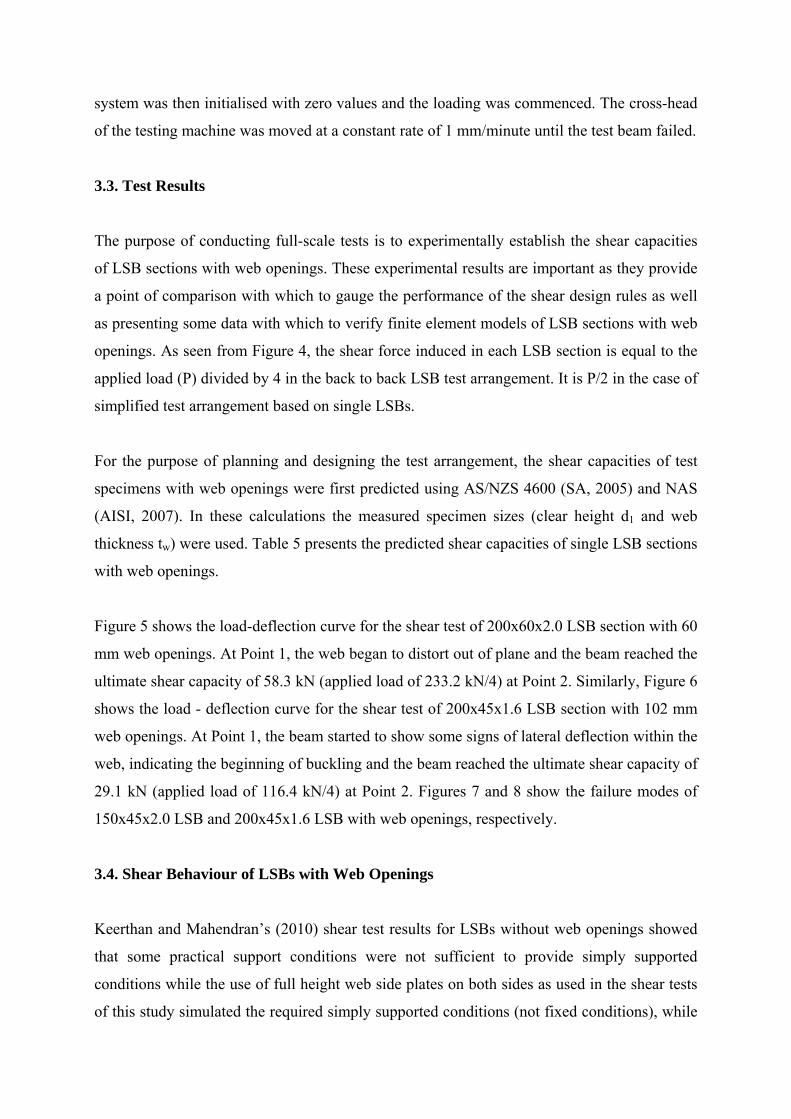
Figure 5 shows the load-deflection curve for the shear test of 200x60x2.0 LSB section with 60
mm web openings. At Point 1, the web began to distort out of plane and the beam reached the
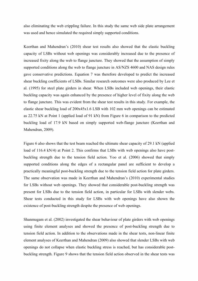
ultimate shear capacity of 58.3 kN (applied load of 233.2 kN/4) at Point 2. Similarly, Figure 6
shows the load - deflection curve for the shear test of 200x45x1.6 LSB section with 102 mm
web openings. At Point 1, the beam started to show some signs of lateral deflection within the
web, indicating the beginning of buckling and the beam reached the ultimate shear capacity of
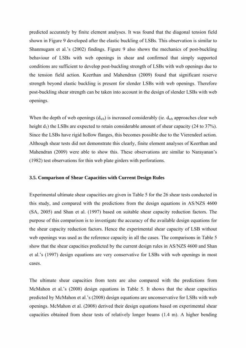
29.1 kN (applied load of 116.4 kN/4) at Point 2. Figures 7 and 8 show the failure modes of
150x45x2.0 LSB and 200x45x1.6 LSB with web openings, respectively.
3.4. Shear Behaviour of LSBs with Web Openings
Keerthan and Mahendran’s (2010) shear test results for LSBs without web openings showed
that some practical support conditions were not sufficient to provide simply supported
conditions while the use of full height web side plates on both sides as used in the shear tests
of this study simulated the required simply supported conditions (not fixed conditions), while
also eliminating the web crippling failure. In this study the same web side plate arrangement
was used and hence simulated the required simply supported conditions.
Keerthan and Mahendran’s (2010) shear test results also showed that the elastic buckling
capacity of LSBs without web openings was considerably increased due to the presence of
increased fixity along the web to flange juncture. They showed that the assumption of simply
supported conditions along the web to flange juncture in AS/NZS 4600 and NAS design rules
gave conservative predictions. Equation 7 was therefore developed to predict the increased
shear buckling coefficients of LSBs. Similar research outcomes were also produced by Lee et
al. (1995) for steel plate girders in shear. When LSBs included web openings, their elastic
buckling capacity was again enhanced by the presence of higher level of fixity along the web
to flange juncture. This was evident from the shear test results in this study. For example, the
elastic shear buckling load of 200x45x1.6 LSB with 102 mm web openings can be estimated
as 22.75 kN at Point 1 (applied load of 91 kN) from Figure 6 in comparison to the predicted
buckling load of 17.9 kN based on simply supported web-flange juncture (Keerthan and
Mahendran, 2009).
Figure 6 also shows that the test beam reached the ultimate shear capacity of 29.1 kN (applied
load of 116.4 kN/4) at Point 2. This confirms that LSBs with web openings also have post-
buckling strength due to the tension field action. Yoo et al. (2006) showed that simply
supported conditions along the edges of a rectangular panel are sufficient to develop a
practically meaningful post-buckling strength due to the tension field action for plate girders.
The same observation was made in Keerthan and Mahendran’s (2010) experimental studies
for LSBs without web openings. They showed that considerable post-buckling strength was
present for LSBs due to the tension field action, in particular for LSBs with slender webs.
Shear tests conducted in this study for LSBs with web openings have also shown the
existence of post-buckling strength despite the presence of web openings.
Shanmugam et al. (2002) investigated the shear behaviour of plate girders with web openings
using finite element analyses and showed the presence of post-buckling strength due to
tension field action. In addition to the observations made in the shear tests, non-linear finite
element analyses of Keerthan and Mahendran (2009) also showed that slender LSBs with web
openings do not collapse when elastic buckling stress is reached, but has considerable post-
buckling strength. Figure 9 shows that the tension field action observed in the shear tests was
predicted accurately by finite element analyses. It was found that the diagonal tension field
shown in Figure 9 developed after the elastic buckling of LSBs. This observation is similar to
Shanmugam et al.’s (2002) findings. Figure 9 also shows the mechanics of post-buckling
behaviour of LSBs with web openings in shear and confirmed that simply supported
conditions are sufficient to develop post-buckling strength of LSBs with web openings due to
the tension field action. Keerthan and Mahendran (2009) found that significant reserve
strength beyond elastic buckling is present for slender LSBs with web openings. Therefore
post-buckling shear strength can be taken into account in the design of slender LSBs with web
openings.
When the depth of web openings (dwh) is increased considerably (ie. dwh approaches clear web
height d1) the LSBs are expected to retain considerable amount of shear capacity (24 to 37%).
Since the LSBs have rigid hollow flanges, this becomes possible due to the Vierendeel action.
Although shear tests did not demonstrate this clearly, finite element analyses of Keerthan and
Mahendran (2009) were able to show this. These observations are similar to Narayanan’s
(1982) test observations for thin web plate girders with perforations.
3.5. Comparison of Shear Capacities with Current Design Rules
Experimental ultimate shear capacities are given in Table 5 for the 26 shear tests conducted in
this study, and compared with the predictions from the design equations in AS/NZS 4600
(SA, 2005) and Shan et al. (1997) based on suitable shear capacity reduction factors. The
purpose of this comparison is to investigate the accuracy of the available design equations for
the shear capacity reduction factors. Hence the experimental shear capacity of LSB without
web openings was used as the reference capacity in all the cases. The comparisons in Table 5
show that the shear capacities predicted by the current design rules in AS/NZS 4600 and Shan
et al.’s (1997) design equations are very conservative for LSBs with web openings in most
cases.
The ultimate shear capacities from tests are also compared with the predictions from
McMahon et al.’s (2008) design equations in Table 5. It shows that the shear capacities
predicted by McMahon et al.’s (2008) design equations are unconservative for LSBs with web
openings. McMahon et al. (2008) derived their design equations based on experimental shear
capacities obtained from shear tests of relatively longer beams (1.4 m). A higher bending
moment was present in their test specimens in comparison to that used in this study. This
appeared to have caused about 30% reduction in the shear capacity of LSB without web
openings reported in McMahon et al. (2008) and hence resulted in the unconservative nature
of their design equations.
It must be noted that experimental shear capacities of LSBs without web openings was used
as the reference value in all cases. Comparison of shear capacities was undertaken to
investigate the accuracy of only the shear capacity reduction factor equations.
It can be seen that the 250x75x2.5 LSB section with 102 mm web openings could not be
tested to failure using the Tinius Olsen testing machine (Capacity of 300 kN). The
300x75x2.5 LSB with 127 mm web openings also posed similar problems. This is why a
simplified experimental arrangement based on single LSB sections with web openings was
used in some tests as mentioned in Table 4.
AS/NZS 4600 (SA, 2005) restricts the depth of web opening to clear height of web ratio
(dwh/d1) to a value of 0.7 while McMahon et al. (2008) restricts it to a value between 0.4 and
0.8. Some shear tests carried out in this research exceeded the above limits of AS/NZS 4600
or McMahon et al.’s (2008) design equations (see Table 5) and hence their equations were not
used in predicting the shear capacities in such cases.
4. Proposed Equations for the Shear Capacity of LSBs with Web Openings
Since the currently available shear capacity equations are either conservative or unsafe, new
equations are proposed for the shear capacity of LSBs with web openings based on
experimental results. It is proposed that the shear capacity of LSB with web openings ( nlV )
can be calculated using a reduction factor qs applied to the shear capacity of LSBs without
web openings ( vV ). This approach is similar to that used in the current cold-formed steel
design codes (SA, 2005, AISI, 2007) and by other researchers (Shan et al., 1997, McMahon et
al., 2008). As described in the previous section, the shear behavioural characteristics of LSBs
with and without web openings are similar in terms of their elastic shear buckling and post-
buckling behaviour and capacities. As for LSBs without web openings, the elastic shear
buckling behaviour of LSBs with web openings was enhanced by the increased web-flange
fixity while they also developed post-buckling strength due to tension field action. However,
the presence of web openings lead to reduced shear capacities for LSBs. Therefore the use of
a shear capacity reduction factor (qs) to the shear capacities of LSBs without web openings is
considered adequate as a simple design method.
Extensive experimental and finite element studies were used to develop accurate shear
capacity equations for LSBs without web openings (Vv), which are presented as Eqs.1 to 13 in
Section 2. Equations 23 and 24 show the proposed design equations for the shear capacity of
LSBs with web openings (Vnl).
for 85.024.01
d
dwh (23)
145.11
d
dq wh
s (24)
where
whd = depth of web openings
1d = clear height of web
qs = shear capacity reduction factor = Vnl/Vv
Table 6 shows the shear capacity reduction factor (qs = Vnl/Vv) and the depth of web openings
to clear height of web ratio (dwh/d1) while Figure 10 shows the non-dimensional curve of qs
versus dwh/d1.
In order to assess the accuracy of the proposed design equations for the shear capacity of
LSBs with web openings (Eq. 24), their predictions are compared with the experimental shear
capacity reduction factors in Table 6. It shows that the shear capacity reduction factors
predicted by Equation 24 agree well with the experimental shear capacity reduction factors.
The mean value of test to predicted shear capacity reduction factor ratio is 1.00 while the
corresponding coefficient of variation (COV) is 0.073. However, it was found that the
proposed design equation (Equation 24) is slightly unconservative when the LSBs have large
web openings (see Figure 10 and Table 6). Further research using detailed finite element
analyses is needed to improve the proposed design equations for the shear capacity of LSBs
with web openings in this region.
vsnl VqV
Figure 11 shows the shear capacities of 200x60x2.0 LSBs as a function of depth of web
opening. It shows that McMahon et al.’s (2008) design equation is unconservative for the
shear capacity of LSBs with web openings while those in AS/NZS 4600 and Shan et al.
(1997) are very conservative for the shear capacity of LSBs with web openings. However,
the proposed design equation was able to predict the experimental shear capacities.
5. Conclusions
This paper has presented the details of an experimental investigation into the shear behaviour
of a new cold-formed hollow flange channel beam known as LiteSteel Beams with web
openings. Twenty six shear tests were undertaken using a three point loading arrangement.
Comparison of ultimate shear capacities from tests showed that AS/NZS 4600 (SA, 2005) and
NAS (AISI, 2007) design equations are conservative for the shear design of LSBs with web
openings. It was found that McMahon et al.’s (2008) design equation is unconservative while
Shan et al.’s (1997) design equations are too conservative for the shear capacity of LSBs with
web openings. Appropriate improvements have been proposed in the form of modified shear
capacity reduction factors to determine the shear capacity of LSBs with web openings based
on experimental results.
Acknowledgements
The authors would like to thank Australian Research Council and OneSteel Australian Tube
Mills for their financial support, and the Queensland University of Technology for providing
the necessary facilities and support to conduct this research project. They would also like to
thank Mr Ross Dempsey, Manager - Research and Testing, OneSteel Australian Tube Mills
for his technical contributions, and his overall support to the many different phases of this
research project.
References
American Iron and Steel Institute (AISI) (2006). Specification for the Design of Cold-formed
Steel Structural Members, AISI, Washington, DC, USA.
American Iron and Steel Institute (AISI) (2007). North American Specification (NAS) for the
Design of Cold-formed Steel Structural Members, AISI, Washington, DC, USA.
Baranda, H., Daly, M. J. and Redwood, R. G. (1978). “Tests of Thin-webbed Beams with
Unreinforced Holes”, ASCE Journal of the Structural Division, Vol. 104, pp. 577 – 595.
Chung, K.F., Ko, A.C.H. and Liu, T.C.H. (2001) “Investigation on Vierendeel Mechanism in
Steel Beams with Circular Web Openings”, Journal of Constructional Steel Research,
Vol. 57, pp. 467 – 490.
Eiler, M.R. (1997). Behaviour of Web Elements with Openings Subjected to Linearly Varying
Shear, Masters Thesis, University of Missouri-Rolla, Missouri-Rolla, USA.
Hagen, N.C., Larsen P.K. and Aalberg, A. (2009). “Shear Capacity of Steel Plate Girders with
Large Web Openings Part I: Modelling and Simulations”, Journal of Constructional Steel
Research, Vol. 65, pp. 65142–150.
Hoglund, T. (1971). “Shear Buckling of Steel and Aluminium Plate Girders”, Journal of
Structural Engineering, The Royal Institute of Technology, Stockholm, Sweden.
Keerthan, P. and Mahendran, M. (2009). Nonlinear Finite Element Analyses of the Shear
Behaviour of LiteSteel Beams with Web Openings, Research Report, Faculty of Built
Environment and Engineering, Queensland University of Technology, Brisbane,
Australia.
Keerthan, P. and Mahendran, M. (2010). “Experimental Studies on the Shear Behaviour and
Strength of LiteSteel Beams”, Engineering Structures, Vol 32, pp. 3235-3247.
Lee, S.C., Davidson, J.S. and Yoo, C. (1995). “Shear Buckling Coefficients of Plate Girder
Web Panels”, Computers and Structures, Vol. 59, pp. 789-795.
LiteSteel Technologies (LST), LiteSteel Beam Products, Brisbane, Queensland, Viewed 10
March, 2009, <www.litesteelbeam.com.au>.
McMahon, B., Peach, T.L., Spear, N. and Wilkinson, T. (2008). “Shear Capacity of LiteSteel
Beams with Circular Web Openings”, Proc. of the Fifth International Conference on
Thin-Walled Structures, Brisbane, Australia, pp. 419-424.
Narayanan, R. (1982). “Shear Capacity of Thin web Plate Girders with Perforations”, Proc. of
the International Bridge Conference, Pennsylvania, USA pp. 445–462.
OneSteel Australian Tube Mills, (OATM) (2008). Design of LiteSteel Beams, Brisbane,
Australia.
Pokharel, N. and Mahendran, M. (2006). Preliminary Investigation into the Structural
Behaviour of LSB Floor Joists Containing Web Openings, Research Report, Queensland
University of Technology, Brisbane, Australia.
Redwood, R.G. and Shrivastava, S.C. (1980). “Design Recommendations for Steel Beams
with Web Holes”, Canadian Journal of Civil Engineering, Vol. 7, pp. 642 – 650.
Shan, M.Y., LaBoube, R.A., Langan, J.E. and Yu, W.W. (1997). “Cold-formed Steel Webs
with Openings: Summary report”, Thin-Walled Structures, Vol. 27, pp. 79 – 84.
Shanmugam, N.E, Lian V.T. and Thevendran, V. (2002). “Finite Element Modelling of Plate
Girders with Web Openings”, Thin-Walled Structures, Vol. 40, pp. 443–464.
Standards Australia/Standards New Zealand (SA) (1998). Australian Standard AS 4100 Steel
Structures, Sydney, Australia.
Standards Australia/Standards New Zealand (SA) (2005). Australia/New Zealand Standard
AS/NZS4600 Cold-Formed Steel Structures, Sydney, Australia.
Yoo, C.H., Lee S.C. and M. (2006). “Mechanics of Web Panel Post-buckling Behaviour in
Shear”, ASCE Journal of Structural Engineering, Vol. 132, pp. 1580-1589.

(a) LSB Section (b) LSB Floor Systems
Figure 1: LiteSteel Beams

Figure 2: LiteSteel Beams with Circular Web Openings for Services
Circular Web Openings
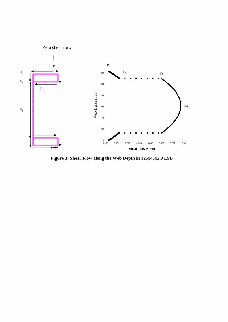
Figure 3: Shear Flow along the Web Depth in 125x45x2.0 LSB
0
20
40
60
80
100
120
0.003 0.004 0.005 0.006 0.007 0.008 0.009 0.01
Shear Flow N/mm
Dis
tan
ce(m
m)
P1
P2 P3
P4
Web
Dep
th (
mm
)
Zero shear flow
P1
P2
P3
P4
(a) Schematic Diagram
Figure 4: Experimental Set-up of Back to Back LSBs with Web Openings
Load
(b) Experimental Set-up
Web Side Plates
T-Shaped Stiffener
Displacement Transducer
Roller Support
P/2 P/2
P

Figure 5: Applied Mid-span Load versus Mid-span Deflection for
200x60x2.0 LSB with 60 mm Web Openings (Aspect Ratio = 1.5)
0
50
100
150
200
250
0 5 10 15
Deflection (mm)
Loa
d (
kN
)
Beam 1
Beam 2
1 2
Ap
pli
ed L
oad
(k
N)
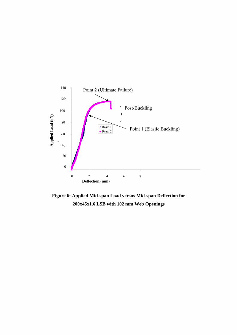
Figure 6: Applied Mid-span Load versus Mid-span Deflection for
200x45x1.6 LSB with 102 mm Web Openings
0.00
20.00
40.00
60.00
80.00
100.00
120.00
140.00
0.00 2.00 4.00 6.00 8.00
Deflection (mm)
Loa
d (
kN
)
Beam 1
Beam 2
Post-Buckling
Point 1 (Elastic Buckling)
Point 2 (Ultimate Failure)
A
pp
lied
Loa
d (
kN)
140
120
100
80
60
40
0
0 2 4 6 8
20
Deflection (mm)
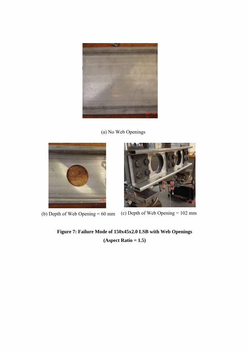
Figure 7: Failure Mode of 150x45x2.0 LSB with Web Openings
(Aspect Ratio = 1.5)
(a) No Web Openings
(b) Depth of Web Opening = 60 mm (c) Depth of Web Opening = 102 mm

Figure 8: Failure Modes of 200x45x1.6 LSB with Web Openings
(Aspect Ratio = 1.5)
(a) No Web Opening
(d) Depth of Web Opening = 127 mm (c) Depth of Web Opening = 102 mm
(b) Depth of Web Opening = 60 mm

(c) Schematic Diagram
Figure 9: Mechanics of LSB with Web Openings Post-buckling Behaviour in Shear
(200x45x1.6 LSB with 102 mm Web Openings)
Tension Band
Web-Flange Junction
LSB
Hollow Flange
Simply Supported Simply
Supported
(a) Experiments (b) FEA Tension band
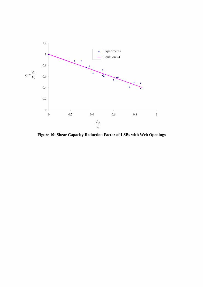
Figure 10: Shear Capacity Reduction Factor of LSBs with Web Openings
v
nls V
Vq
0
0.2
0.4
0.6
0.8
1
1.2
0 0.2 0.4 0.6 0.8 1
Experimental Results
Equation 8.24
Experiments
Equation 24
1d
dwh
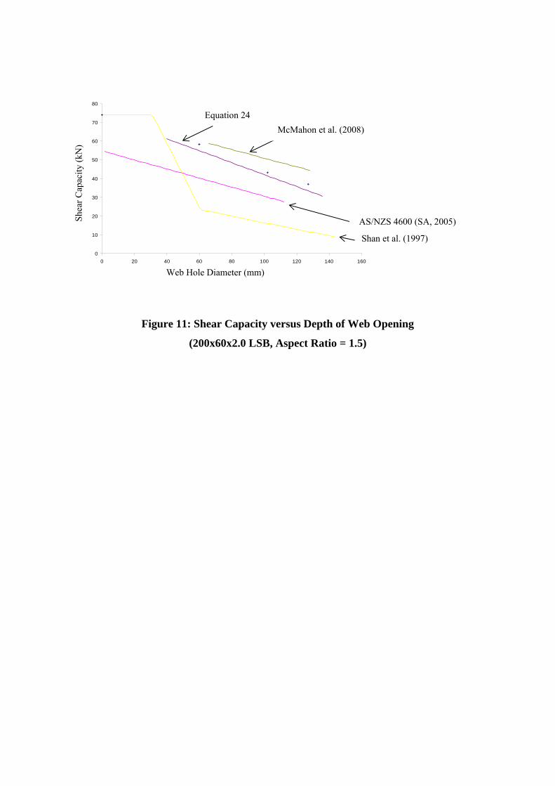
Figure 11: Shear Capacity versus Depth of Web Opening
(200x60x2.0 LSB, Aspect Ratio = 1.5)
0
10
20
30
40
50
60
70
80
0 20 40 60 80 100 120 140 160
Web Hole Diameter (mm)
Sh
ear
Cap
acit
y (k
N)
Shan et al. (1997)
McMahon et al. (2008)
Equation 24
AS/NZS 4600 (SA, 2005)
Web Hole Diameter (mm)
S
hear
Cap
acity
(kN
)
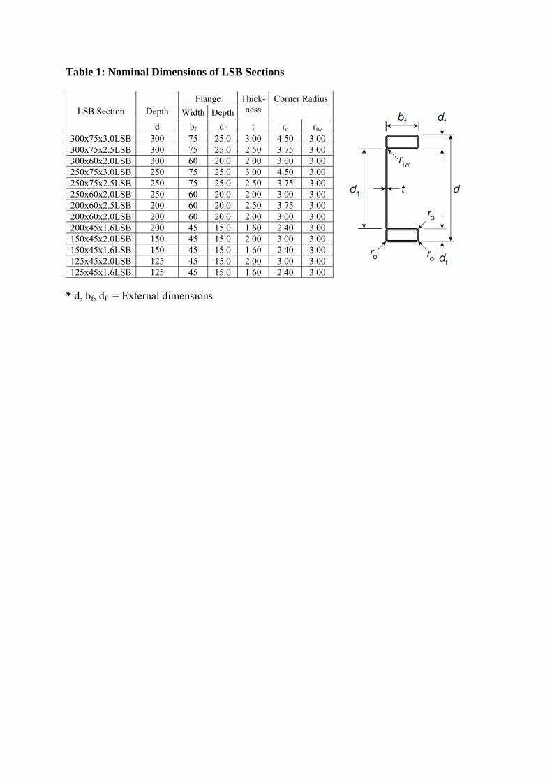
Table 1: Nominal Dimensions of LSB Sections
LSB Section
Depth
Flange Thick-ness
Corner Radius Width Depth
d bf df t ro riw 300x75x3.0LSB 300 75 25.0 3.00 4.50 3.00 300x75x2.5LSB 300 75 25.0 2.50 3.75 3.00 300x60x2.0LSB 300 60 20.0 2.00 3.00 3.00 250x75x3.0LSB 250 75 25.0 3.00 4.50 3.00 250x75x2.5LSB 250 75 25.0 2.50 3.75 3.00 250x60x2.0LSB 250 60 20.0 2.00 3.00 3.00 200x60x2.5LSB 200 60 20.0 2.50 3.75 3.00 200x60x2.0LSB 200 60 20.0 2.00 3.00 3.00 200x45x1.6LSB 200 45 15.0 1.60 2.40 3.00 150x45x2.0LSB 150 45 15.0 2.00 3.00 3.00 150x45x1.6LSB 150 45 15.0 1.60 2.40 3.00 125x45x2.0LSB 125 45 15.0 2.00 3.00 3.00 125x45x1.6LSB 125 45 15.0 1.60 2.40 3.00
* d, bf, df = External dimensions
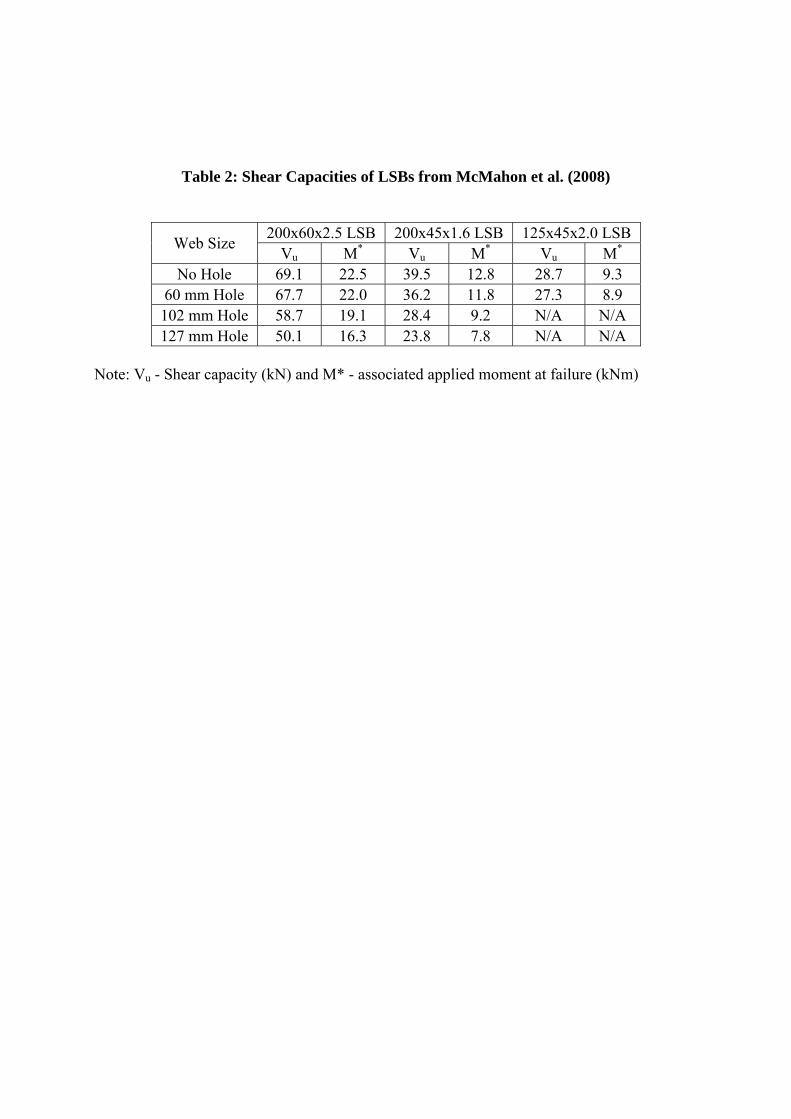
Table 2: Shear Capacities of LSBs from McMahon et al. (2008)
Web Size 200x60x2.5 LSB 200x45x1.6 LSB 125x45x2.0 LSB
Vu M* Vu M* Vu M* No Hole 69.1 22.5 39.5 12.8 28.7 9.3
60 mm Hole 67.7 22.0 36.2 11.8 27.3 8.9 102 mm Hole 58.7 19.1 28.4 9.2 N/A N/A 127 mm Hole 50.1 16.3 23.8 7.8 N/A N/A
Note: Vu - Shear capacity (kN) and M* - associated applied moment at failure (kNm)
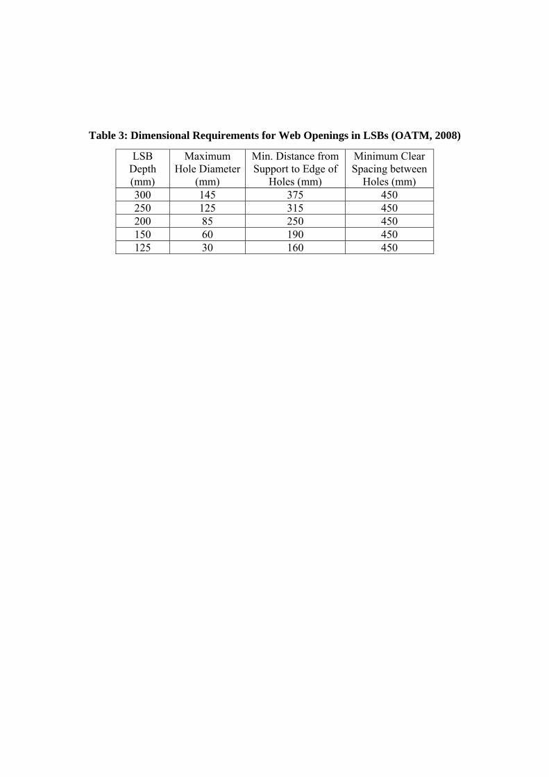
Table 3: Dimensional Requirements for Web Openings in LSBs (OATM, 2008)
LSB Depth (mm)
Maximum Hole Diameter
(mm)
Min. Distance from Support to Edge of
Holes (mm)
Minimum Clear Spacing between
Holes (mm) 300 145 375 450 250 125 315 450 200 85 250 450 150 60 190 450 125 30 160 450

Table 4: Details of LSB Test Specimens with Web Openings
(Aspect Ratio = 1.5)
No. LSB
Section fyw
(MPa) tw
(mm) d1
(mm) d1/tw
dwh
(mm) dwh/d1
1 150x45x1.6
454.2 1.58 120.0 75.9 0 0.00 2 454.2 1.58 120.0 75.9 60 0.50 3 454.2 1.58 120.0 75.9 102 0.85 4
150x45x2.0 422.6 1.97 120.0 60.9 0 0.00
5 422.6 1.97 120.0 60.9 60 0.50 6 422.6 1.97 120.0 60.9 102 0.85 7
200x45x1.6
452.1 1.61 169.6 105.3 0 0.00 8 452.1 1.61 169.6 105.3 60 0.35 9 452.1 1.61 169.6 105.3 102 0.60 10 452.1 1.61 169.6 105.3 127 0.75 11
200x60x2.0
440.4 1.97 160.0 81.2 0 0.00 12 440.4 1.97 160.0 81.2 60 0.38 13 440.4 1.97 160.0 81.2 102 0.64 14 440.4 1.97 160.0 81.2 127 0.79 15
250x75x2.5
446.0 2.51 201.0 80.1 0 0.00 16 446.0 2.51 201.0 80.1 60 0.30 17 446.0 2.51 201.0 80.1 102 0.51 18 446.0 2.51 201.0 80.1 127 0.63 19
300x75x2.5
449.1 2.51 250.0 99.6 0 0.00 20 449.1 2.51 250.0 99.6 60 0.24 21 449.1 2.51 250.0 99.6 102 0.41 22 449.1 2.51 250.0 99.6 127 0.51 23
300x75x3.0
440.1 2.86 250.0 87.4 0 0.00 24 440.1 2.86 250.0 87.4 60 0.24 25 440.1 2.86 250.0 87.4 102 0.41 26 440.1 2.86 250.0 87.4 127 0.51
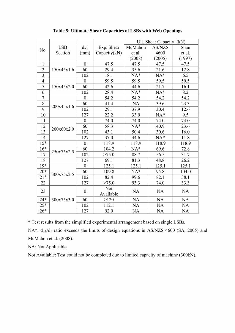
Table 5: Ultimate Shear Capacities of LSBs with Web Openings
No. LSB
Section dwh
(mm) Exp. Shear
Capacity(kN)
Ult. Shear Capacity (kN) McMahon
et al. (2008)
AS/NZS 4600
(2005)
Shan et al.
(1997) 1
150x45x1.6 0 47.5 47.5 47.5 47.5
2 60 29.4 35.6 21.6 12.8 3 102 18.1 NA* NA* 6.5 4
150x45x2.0 0 59.5 59.5 59.5 59.5
5 60 42.6 44.6 21.7 16.1 6 102 28.4 NA* NA* 8.2 7
200x45x1.6
0 54.2 54.2 54.2 54.2 8 60 41.4 NA 39.6 23.3 9 102 29.1 37.9 30.4 12.6 10 127 22.2 33.9 NA* 9.5 11
200x60x2.0
0 74.0 74.0 74.0 74.0 12 60 58.3 NA* 40.9 23.6 13 102 43.1 50.4 30.6 16.0 14 127 37.0 44.6 NA* 11.8 15*
250x75x2.5
0 118.9 118.9 118.9 118.9 16* 60 104.2 NA* 69.6 72.8 17 102 >75.0 88.7 56.5 31.7 18 127 69.1 81.3 48.8 26.2 19*
300x75x2.5
0 125.1 125.1 125.1 125.1 20* 60 109.8 NA* 95.8 104.0 21* 102 82.4 99.6 82.1 38.1 22 127 >75.0 93.3 74.0 33.3
23
300x75x3.0
0 Not
Available NA NA NA
24* 60 >120 NA NA NA 25* 102 112.1 NA NA NA 26* 127 92.0 NA NA NA
* Test results from the simplified experimental arrangement based on single LSBs.
NA*: dwh/d1 ratio exceeds the limits of design equations in AS/NZS 4600 (SA, 2005) and
McMahon et al. (2008).
NA: Not Applicable
Not Available: Test could not be completed due to limited capacity of machine (300kN).
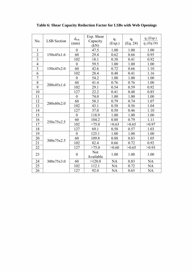
Table 6: Shear Capacity Reduction Factor for LSBs with Web Openings
No. LSB Section dwh
(mm)
Exp. Shear Capacity
(kN)
qs (Exp.)
qs (Eq. 24) )24.(
.)(
Eqq
Expq
s
s
1 150x45x1.6
0 47.5 1.00 1.00 1.00 2 60 29.4 0.62 0.66 0.95 3 102 18.1 0.38 0.41 0.92 4
150x45x2.0 0 59.5 1.00 1.00 1.00
5 60 42.6 0.72 0.66 1.10 6 102 28.4 0.48 0.41 1.16 7
200x45x1.6
0 54.2 1.00 1.00 1.00 8 60 41.4 0.76 0.76 1.00 9 102 29.1 0.54 0.59 0.92 10 127 22.2 0.41 0.48 0.85 11
200x60x2.0
0 74.0 1.00 1.00 1.00 12 60 58.3 0.79 0.74 1.07 13 102 43.1 0.58 0.56 1.04 14 127 37.0 0.50 0.46 1.10 15
250x75x2.5
0 118.9 1.00 1.00 1.00 16 60 104.2 0.88 0.79 1.11 17 102 >75.0 >0.63 >0.65 >0.97 18 127 69.1 0.58 0.57 1.03 19
300x75x2.5
0 125.1 1.00 1.00 1.00 20 60 109.8 0.88 0.83 1.05 21 102 82.4 0.66 0.72 0.92 22 127 >75.0 >0.60 >0.65 >0.93
23
300x75x3.0
0 Not
Available 1.00 1.00 1.00
24 60 >120.0 NA 0.83 NA 25 102 112.1 NA 0.72 NA 26 127 92.0 NA 0.65 NA


![Rainbow Heart - artecy.com · 7777777 777777777 7777777777777 ooooooo 77777 7777777 7777777777777 oooooo]]]]] ddd ddd ddd ddd ddd ™™™™™™™™™™™ ™™™™™™™™™™™™™™™™™](https://static.fdocuments.in/doc/165x107/5f4a4ec8ec2fea16bc048a6a/rainbow-heart-7777777-777777777-7777777777777-ooooooo-77777-7777777-7777777777777.jpg)