This document is disseminated under the sponsorship of the ... · DOT/FAAIRD-90T7 Helicopter...
52
DOT/FAAIRD-90T7 Helicopter Rejected Research and Development Service Requirements Washington, D.C. 20591 AD-A2 43 738 Edwin D. McConkey Robert J. Hawley Robert K. Anoll Systems Control Technology, Inc. D TICms " - 1611 N. Kent Street, Suite 910 In) I Arlington, VA 22209 E'LECTE DEC 3 0 1991 August 1991 Final Report ': "".......'- . This document is available to the public _. . .. ;. through the National Technical Information Service, Springfield, Virginia 22161. 0 U.S. Department ,,)f Transportation Federal Aviation 91-19231 Administration flflfl*E 91 122 i 109
Transcript of This document is disseminated under the sponsorship of the ... · DOT/FAAIRD-90T7 Helicopter...
DOT/FAAIRD-90T7 Helicopter Rejected
Research and Development Service RequirementsWashington, D.C. 20591
AD-A24 3 738 Edwin D. McConkey
Robert J. HawleyRobert K. Anoll
Systems Control Technology, Inc.D TICms " - 1611 N. Kent Street, Suite 910
In) I Arlington, VA 22209E'LECTE
DEC 3 0 1991
August 1991
Final Report
': "".......'- . This document is available to the public_. . .. ;. through the National Technical Information
Service, Springfield, Virginia 22161.
0U.S. Department,,)f Transportation
Federal Aviation
91-19231 Administration
flflfl*E 91 122 i 109

This document is disseminated under the sponsorship of the U.S. Departmentof Transportation in the interest of information exchange. The UnitedStates Government assumes no liability for the contents or use thereof.

Technical Report Documentation Page
1. Report No. 2. Government Accession No. 3. Recipients Catalog No.
DOT/FAA/R D-90/7
4. Title and Subtitle 5. Report DateAugust 1991
Helicopter Rejected Takeoff Airspace Requirements 6. Performing Organization Code
7. Author (s) 8. Performing Organization Report No.
Edwin D. McConkey, Robert J. Hawley, Robert K. Anoll SCT 91 RR-28
9. Performing Organization Name and Address 10. Work Unit No. (TRAIS)Systems Control Technology, Inc.1611 North Kent Street, Suite 910 11. Contract or Grant No.Arlington, Virginia 22209 DTFA01-87-C-00014
12. Sponsoring Agency Name and Address 13. Type Report and Period CovereaU.S. Department of Transportation Final ReportFederal Aviation Administration800 Independence Avenue, S.W. 14. Sponsoring Agency CoceWashington. D.C. 20591 ARD-30
15. Supplementary Notes
ARD - 30 - Vertical Flight Program OfficeAAS - 100 - Design and Operations Criteria Division
16. Abstract
This report is an analysis of performance data for helicopters that are certified for one engine inoperative (OEI)performance. It relates rejected takeoff and OEI capability to airspace requirements for heliports intended tosupport Category A operations. The current FAA regulation defining protected airspace and the imaginarysurfaces associated with heliports does not take into consideration emergency situations involving engine failuresduring takeoff and landing operations. That is, the air and ground space defined by this regulation provides nomargin of safety for acceleration or stopping distance for a rejected takeoff. Furthermore, it defines departurepaths (climbout angles) that are too steep for many helicopters' OEI climbout capability. This report. therefore,suggests a more flexible airspace system, based on helicopter performance, that should apply to protectedairspace at heliports supporting Category A operations.
This is one of a series of five reports that addresses helicopter performance profiles and their relationship to theVFR protected imaginary surfaces of approaches and departures at heliports. The other four are:
1) Helicopter Physical and Performance Data, DOT/FAA/RD-90/3,2) Heliport VFR Airspace Design Based on Helicopter Performance, DOT/FAA/RD-90/4,3) Operational Survey - VFR Heliport Approaches and Departures, DOT/FAA/RD-90-5, and4) Rotorcraft Acceleration and Climb Performance Model, DOT/FAA/RD-90-6.
17. Key Words 18. Distribution Statement
Rotvrcraft Helicopter This document is available to the publicHelicopter Performance Airspace through the National Technical InformationOne Engine Inoperative Rejected Takeoff Service, Springfield, Virginia 22161.
19. Securty Classif. (of this report) 20. Security Classif. (of this page) 1. No. of Pages 22. PriceUnclassified Unclassified r52
Form DOTf F i700.7 (8-72) Reproduction of this document is authorized

TABLE OF CONTENTS
Page
1.0 Introduction................ .............................. 11 .i Backgroun d .................................................. 21 .2 Objectives .................................................. 2
2.0 Study Methodology ................................................ 32 1 Review of Applicable Documentation .......................... 32.2 Selection of Representative Helicopters ..................... 32.3 Performance Data Collector ................................. A
2.4 Operational Survey .......................................... 52.5 Airspace Requirements Comparison ............................ 5
3.0 Regulatory Analysis ................................ ............. 73.1 Discussion of the Regulatory Requirements ................... 7
3.1.1 Heliport Airspace Regulations ........................ 73.1.2 Helicopter Regulatory Requirements ................. 9
3.1.2.1 Part 27 Performance CertificationRequirements ................................ 9
3.1.2.2 OEI Performance Data Contained in Part 27Flight Manuals ...................... ....... 10
3.1.2.3 Part 29, Category A PerformanceCertification Requirements .................. 10
3.1.2.4 Performance Data Contained in Part 29Rotorcraft Flight Manuals .................. 12
3.1.2.5 Adequacy of Flight Manuals for RejectedTakeoff Operations .......................... 13
3.2 Analysis of the Operational Procedures ...................... 133.2.1 Category A Departure ................................. 133.2.2 Vertical Departure ................................... 14
4.0 Pertormance Analysis ............................................. 174.1 Conventional Category A Takeoff Procedures .................. 174.2 Vertical Takeoff ..................................... 294.3 Operational Performance Considerations ....................294.4 Comparison of Performance Data with Heliport Airspace
Protect ion .................................................. 34
5.0 Conclusions and Recommendations .................................. 355 .1 Conclusions ................................................. 355.2 Recommendations ............................................. 35
References ............................................................ 3 A c sio: orN4TIS , ,.&
Appendix A Excerpts from the FAA Helicopter Certification L~1C 7A.Regulations ........................................... A-i U.:.;:'c:,ci
Appendix B Excerpts from Advisory Circular 29 - 2ACategory A Takeoffs .............................. ....... B-i 8
• i~~~. : ,...I" " o
D Ar
iii '..---Oa
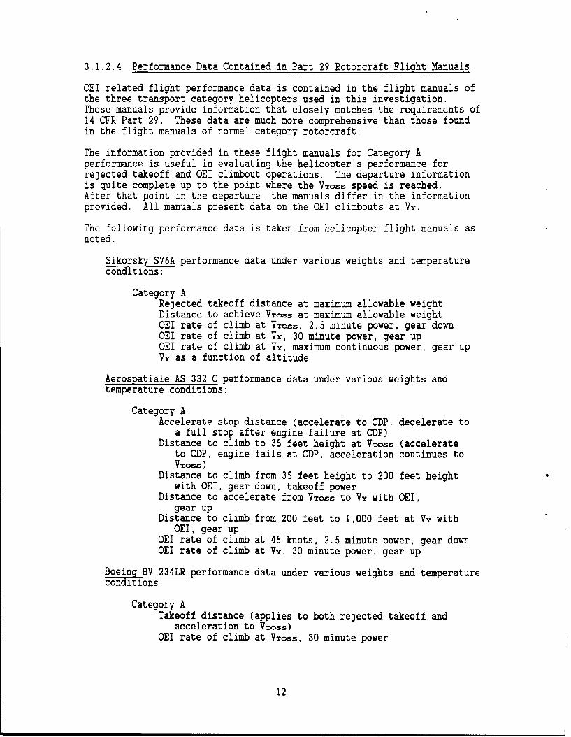
LIST OF FIGURES
Page
Figure 1 Heliport Imaginary Surfaces ................................. 8Figure 2 Takeoff Performance Category A .............................. 14Figure 3 Category A Vertical Takeoff Profile - Ground Level .......... 15Figure 4 Category A Vertical Takeoff Profile - Pinnacle .............. 15Figure 5 Rejected Takeoff Distance AS 332 C .......................... 18Figure 6 Distance to VTOSs AS 332 C .................................. 19Figure 7 OEI Climb Angle At VToss AS 332 C ........................... 20Figure 8 OEI Climb Angle At VTOSs BV 234LR ........................... 22Figure 9 Rejected Takeoff Distance S76A .............................. 23Figure 10 Distance to VTOSS S76A ...................................... 24Figure 11 OEI Climb Angle At VToss S76A ............................... 25Figure 12 Rejected Takeoff Distance MBB BO 105 CBS .................... 26Figure 13 Distance to VToss MBB BO 105 CBS ............................ 27Figure 14 OEI Climb Angle At Vy MBB BO 105 CBS ........................ 28Figure 15 OEI Climb Angle At VToss AS 355 F ........................... 30Figure 16 Vertical Takeoff Limitations AS 322C ........................ 31
LISTING OF TABLES
Table 1 Helicopters Selected for Detailed Analysis ................... 4Table 2 Weight Reduction for the Vertical Takeoff - AS 332C .......... 29
iv

1.0 INTRODUCTION
The current Federal regulation defining protected airspace surfaces aroundheliports is based on helicopters performing normal takeoff and landingoperations. Emergency situations involving engine failures are notconsidered in the establishment of these protected surfaces.
In an effort to develop a better understanding of the implications offailed engine conditions on city-center heliport development and heliportprotected airspace requirements, the FAA initiated a study project tocollect data regarding the performance of representative Category Ahelicopters in the current civil fleet. This report contains the data,analyses, conclusions and recommendations that were produced by thatstudy.
This report is one of a series of five that addresses helicopterperformance profiles and their relationships to approach and departureprotected surfaces around heliports. The others are:
Helicopter Physical and Performance Data, DOT/FAA/RD-90/3:
Contains physical and performance data for eight civilhelicopters. The data were taken from a number of sources toinclude aircraft flight manuals, industry publications, andcomputer performance simulations.
Operational Survey - VFR Heliport Approaches and Departures,DOT/FAA/RD-90/5:
Presents the results of a field survey which collected pilots'opinions about their helicopter performance and operationalconsiderations. Survey results are compared with the performancedata contained in "Helicopter Physical and Performance Data."
Heliport VFR Airspace Based on Helicopter Performance,DOT/FAA/RD-90/4:
Applies the data contained in DOT/FAA/RD-90/3 and DOT/FAA/RD-90/5to the issue of vertical airspace protected surfaces around theheliport. Additionally, the report develops a heliportairspace/helicopter performance system that allows operationalcredit for performance capability.
Rotorcraft Acceleration and Climb Performance Model, DOT/FAA/RD-90/6:
Presents the methodology and computer programs used to developthe helicopter departure profiles presented in "HelicopterPhysical and Performance Data."
The report contained herein is an analysis of performance data forhelicopters that are certificated to have one engine inoperative (OEI)performance capability. This capability is known in the industry asCategory A. These data were developed from information contained in thehelicopter flight manuals. The report relates rejected takeoff and OEIperformance capability to airspace requirements for those heliports whereCategory A operations are of concern.

1.1 BACKGROUND
The study of airspace requirements for failed engine situations naturallylimits the scope of the effort to multiengine rotorcraft. The singleengine aircraft with a failed engine is obviously going to be forced toland. Because the failure can occur anywhere along the takeoff path, theresultant protected airspace must be large to accommodate an autorotationto a landing in a clear area.
Pilots of multiengine rotorcraft however are faced with a choice in afailed engine situation: reject the takeoff and land, or continue thetakeoff with one engine inoperative (OEI). In developing certificationcriteria for transport category rotorcraft, the FAA has carefully con-sidered the failed engine scenario. Specific requirements, establishedunder Category A, are contained in the regulations under Title 14 of theCode of Federal Regulations (14 CFR), Part 29, Transport Category Rotor-craft. While it is recognized that only a small portion of the helicopterpopulation is certified for Category A, and an even smaller numberactually operate Category A, forecasts of increases in Part 29 operationsover time and their impact on the industry must be considered in thedevelopment of heliport design standards. For those rotorcraft certifiedunder Part 27, Normal Category Rotorcraft, (rotorcraft with a maximumgross weight of 6,000 pounds or less), there are no specific requirementsto demonstrate Category A capabilities. However, some manufacturers ofmultiengine helicopters choose to provide some Category A performance datain the helicopter flight manuals even though it is not required.
In pursuing this investigation, a considerable amount of helicopterperformance data were generated for the helicopters that were selected fordetailed analysis. It is appropriate to note that it was not the intentof this study to perform a comparative analysis of the performancecapabilities of these aircraft. The performance data presented in thisreport and its two companion reports were developed using assumptions andguidelines specifically aimed at investigating the design of heliports inconfined areas. Therefore, these data do not necessarily reflect theperformance capabilities of these helicopters in a broader operational oreconomic context.
1.2 OBJECTIVES
The overall objective of this study was to recommend improvements toairspace protection surfaces at heliports based on rejected takeoff andOEI takeoff conditions. In pursuing this objective, the following areasof study were taken into consideration:
a. applicable parts of the heliport airspace protection regulation andsupporting documentation,
b. applicable parts of the helicopter certification regulations and
supporting documentation,
c. takeoff procedures used in the certification of the helicopter,
d. takeoff procedures recommended in the helicopter flight manuals,
e. performance data contained in the helicopter flight manuals, and
f. data from other sources found in the open literature.2

2.0 STUDY METHODOLOGY
The methodology used to investigate heliport airspace requirements basedon OEI helicopter performance is described in this section.
2.1 REVIEW OF APPLICABLE DOCUMENTATION
The study was initiated with a review of the applicable FAA regulatorydocuments, primarily Title 14 of the Code of Federal Regulations (14 CFR)and FAA Advisory Circulars (AC). In particular, the following parts ofthe regulations were reviewed:
14 CFR Part 77, Objects Affecting Navigable Airspace; Subpart C,Obstruction Standards; Paragraph 77.29, Airport imaginary surfaces forheliports,
14 CFR Part 27, Airworthiness Standards: Normal Category Rotorcraft,Subpart B, Flight - Performance, and
14 CFR Part 29, Airworthiness Standards: Transport CategoryRotorcraft, Subpart B, Flight - Performance.
in addition the companion Advisory Circulars relating to these regulationswere reviewed. These ACs included:
AC 150/5390-2, "Heliport Design," January 4, 1988,
AC 27-1, "Certification of Normal Category Rotorcraft," August 29,1985, and
AC 29-2A, "Certification of Transport Category Rotorcraft,"September 16, 1987.
Next, available sources of helicopter performance data were reviewed.These included helicopter flight manuals and reports in the openliterature.
2.2 SELECTION OF REPRESENTATIVE HELICOPTERS
Following an initial evaluation of capabilities, a representative set ofhelicopters was selected for detailed OEI performance assessments.Selected helicopters along with basic capabilities data are shown intable 1. The selection of these helicopters was based on a combination offactors to include availability of data, mix of weights, mix of IFR andVFR., and mix of normal and transport category rotorcraft.
3

TABLE I HELICOPTERS SELECTED FOR DETAILED ANALYSIS
Percent ofGross No. of Twin Turbine Performance
Helicopter Wt (ibs) Enaines Fleet IFR/VFR Category
Aerospatiale 355F 5,071 2 12.4 VFR/IFR NCRMBB BO 105 CBS 5,291 2 12.6 VFR NCRSikorsky S76A 10,500 2 16.5 VFR/IFR TCR/A/BAerospatiale 332C 18,959 2 0.2 VFR/IFR TCR/A/BBoeing Vertol 234LR 48,500 2 0.5 VFR/IFR TCR/A
VFR - Certified for Visual Flight Rules OperationsIFR - Certified for Instrument Flight Rules OperationsNCR - Normal Category RotorcraftTCR/A/B - Transport Category Rotorcraft, Categories A and BTCR/A - Transport Category Rotorcraft, Category A
2.3 PERFORMANCE DATA COLLECTION
Helicopter flight manuals were used as the primary source of takeoffperformance data. These data are in the form o: engineering graphs andmust be organized into a meaningful operational context. Conditions ofweight, temperature and field elevation were selected for this purpose.These conditions included:
a. aircraft weight - 70, 85 and 100 percent of maximun grossweighL,
b. field elevation - sea level, 2000 and 4000 feet, andc. temperatures - ISA and ISA - 20 degrees C-.
- Weights were reduced to the maximum allowable under theapplicable density altitude conditions.
"ISA - temperature profile of the international StandardAtmosphere.
:n addition, profiles were evaluated for applicable takeoff procedures, t:include:
a. Category A takeoff procedures,b. vertical takeoff procedures, where applicabie, andc. OEI climbout procedures.
The following speeds are performance related and are used throuahout forcomparison:
a. VTOSS - Takeoff Safety Speed. The speed at which 100 FPM rate ofclimb is assured for all combinations of weight, altitude, temperatureand center of gravity, for which takeoffs are to be scheduled.vross is determined with tne landing gear extended, the criticalengine inoperative and the remaining engine(s) within aprrnvedoperating limits.
4

b. W - Best Rate of Climb Speed. The speed at which the maximum
rate of climb can be achieved.
2.4 OPERATIONAL SURVEY
A survey was performed of 88 operators perforwing various missions inlocations throughout the United States. The survey was performed tocollect information on current practices for VFR arrival and departureprocedures at heliports. The intent of the survey was to supplementnelicopter performance information derived from certification data withsubjective performance information derived from current operationalpractices.
:he survey did not specifically address safety issues such as rejectedtakeoff, E takeoff, or loss of engine procedures. However, during thecourse of the survey some information on topics related to these safetyissues was obtained. This information is discussed in section 4.3,Operational Performance Considerations.
2.5 A:RSPACE REQU:REKENTS COARISON
c7llowing the data collection effort was a comparison of the OEI takeoffperformance data with the current heliport design standards. The analysisidentified areas where OE: performance is unable to meet the protectedairspace requirements established in these standards.
:'he results of these comparisons were summarized into a set of require-ments for heliport protection surfaces to account for the possibility ofan engine failure on takeoff. The final activity in the investigation wasidentification of specific conclusions and recommendations based on thefindings of the research effort.
5

3.0 REGULATORY ANALYSIS
This section of the report describes the data and the analyses thatsupport the heliport protected airspace requirements in consideration C:engine failure situations.
3.! DISCUSSION OF TH REGULATORY REQUIR ENTS
The regulatory reqauirements associated with operations and airspace atheliports can be divided into two general categories; those dealing withthe heliport, and those related to the performance of the helicopterduring takeoff with failed engine conditions.
3.:.1 Heliport Airspace Regulations
The airspace around airports and heliports is monitored by the FAA throu-14 CFR Part 77, Objects Affecting Navigable Airspace. identificatic cfobstacles resulting from new construction or alteration of existingstructures which may be obstructions to air navigation is accomplished bydefining a series of imaginary surfaces in the vicinity of airports an-heliports. Objects that penetrate these surfaces must be evaluated todetermine the impact on air navigation. Part 77 of 14 'FR defines theimaginary surfaces for heliports as follows:
Paragraph 77.29 Airport imaginary surfaces for heliports.
(a) Heliport primary surface. The area of the primary surfacecoincides in size and shape with the designated take-off and landinaarea of a heliport. This surface is a horizontal plane at theelevation of the established heliport elevation.
(b) Heliport approach surface. The approach surface begins ateach end of the heliport primary surface with the sane width as theprimary surface, and extends outward and upward for a horizontaldistance of 4,000 feet where its width is 500 feet. The slope of theapproach surface is 8 to 1 for civil heliports and 10 to 1 formilitary heliports.
(c) Heliport transitional surfaces These surfaces extend outwardand upward from the lateral boundaries of the heliport primary surfaceand from the approach surfaces at a slope of 2 to I for a distance of250 feet measured horizontally from the centerline of the primary anoapproach surfaces.
The heliport imaginary surfaces are shown in figure 1.
Of primary interest to this investigation is the slope of the heliportapproach surface which is set at 8 to 1 for civil heliports. This slopecorresponds to an angle of 7.125 degrees above the horizon. This slopebegins at the approach edge of the takeoff and landing area.
Additional information on the airspace requirements for heliports can befound in the FAA Advisory Circular 150/5390-2, Heliport Design. Inaddition to describing the heliport primary and approach surfaces, the AC
7

500' (152 m) -
u. 250 -
(76 m)
/ NOTES: 1. ALTHOUGH THE FIGURE ILLUSTRATES
,A STRAIGHT-IN APPROACH, THE
APPROACH MAY INCLUDE CURVES TO
250' THE LEFT OR RIGHT TO AVOID
(76 m) IOBJECTS OR NOISE SENSITIVE AREAS.
2. THE PRIMARY SURFACE IS PHYSICALLY
w -5001 (152 m) IDENTICAL TO THE TAKEOFF AND
LANDING AREA.
FIGURE 1 HELIPORT IMAGINARY SURFACES
8

defines a visual approach and departure protection area which coincideswith the first 280 feet of the heliport approach surface nearest theheliport primary surface. The AC recommends that the heliport operatorown or control the property underlying the protection area, that it bereasonably free of surface irregularities or objects, while permittingheliport related uses which do not create a hazardous condition.
Heliport Design (AC 150/5390-2) standards are advisory only, unless theheliport is a public use facility that is funded or administered by thefederal government.
3.1.2 Helicopter Regulatory Requirements
Helicopters are certified by thL FAA under 14 CFR, Parts 27 and 29.Part 27 applies to Normal Category Rotorcraft with maximum weight of 6,000pounds. Part 29, Transport Category Rotorcraft, applies to helicoptersweighing over 6,000 pounds. Part 29 helicopters are further divided intoCategory A or Category B. Current Category A and Category B requirementsare stated below, however, helicopters certified prior to 1983 do not havethe seating requirements applied.
All helicopters with maximum weight greater than 20,000 pounds, and having10 or more passenger seats, must meet Category A requirements.Helicopters weighing more than 20,000 pounds, but having nine or lesspassenger seats, may be certified as Category B providing the helicoptermeets Category A requirements in the areas of strength (subpart C), designand construction (subpart D), powerplant (subpart E) and equipment(subpart F). Part 29 helicopters weighing 20,000 pounds or less andhaving 10 or more passenger seats may be certified as Category B providingthe helicopter meets Category A requirements for strength, design andconstruction, powerplant and equipment, as well as the one engineinoperative (para 29.67) and conditions to determine the limitingheight-speed envelope required by para 29.79 and 29.1513.
Part 29 helicopters weighing 20,000 pounds or less and having nine or less
passenger seats may be certified as Category B.
3.1.2.1 Part 27 Performance Certification Reauirements
The performance requirements of interest in this investigation arecontained in paragraphs:
27.51 Takeoff; and27.67 Climb: one engine inoperative (OEI).
Appendix A contains applicable sections of the regulations for referencepurposes. The following paragraphs summarize the main elements of theseregulations as they apply to rejected takeoff and OEI climbout operationsfor normal category rotorcraft.
9

General
Performance requirements must be met for still air and standardatmosphere, must correspond to the engine power available underparticular atmospheric conditions, and be based upon approved enginepower less installation losses and losses associated with the op-eration of accessories.
Takeoff
The takeoff procedure must not require exceptional piloting skill orexceptionally favorable conditions.
Takeoffs must be made in such a manner that a landing can be madesafely at any point along the flight path in the event of an enginefailure.
Climb with One Engine Inoperative (OEI)
At VY, or at a speed for minimum rate of descent, the steady rate ofclimb (or descent) must be determined at maximum gross weight, withone engine inoperative, and maximum continuous power (except when30-min power certification is requested).
3.1.2.2 OEI Performance Data Contained in Part 27 Flight Manuals
The MBB BO 105 manual contained nearly as much Category A takeoffperformance information as did the three Part 29 aircraft. Rejectedtakeoff distances and distances to achieve Takeoff Safety Speed (VToss)were available in engineering graph formats. The MBB B0105 and theAS 355F manuals contained OEI rate of climb data at VY, but not atVTOSS.
3.1.2.3 Part 29, Category A Performance Certification Reauirements
The performance requirements of interest in this investigation arecontained in Paragraphs:
29.51 Takeoff data: general;29.53 Takeoff: Category A;29.59 Takeoff path: Category A; and29.65 Climb: one engine inoperative.
Appendix A contains applicable sections of the regulations. The followingparagraphs summarize the main elements of these regulations as they applyto takeoff and approach operations. Appendix B contains applicablesections from FAA Advisory Circular 29-2A, Certification of TransportCategory Rotorcraft, applicable to rejected takeoff and OEI climboutrequirements.
General
Performance requirements must be met for still air and standardatmosphere, must correspond to the engine power available underparticular atmospheric conditions, and be based upon approved enginepower less installation losses and losses associated with theoperation of accessories.
10

Takeoff Data: General
No takeoff applicable to demonstrating the performance of the aircraftfor certification shall require exceptional piloting skill orexceptionally favorable conditions.
Takeoff: Category A
The takeoff performance must show that, if one engine fails at anytime after the start of takeoff, the aircraft can either return to,and stop safely on the takeoff area, or continue the takeoff andclimbout to attain at least:
VTOSs and an altitude of 35 feet and then climb to 100 feetabove the takeoff surface. VTOSS is the minimum speed at which100 fpm rate of climb can be achieved while avoiding the limitingH-V envelope.
150 ft/min. rate of climb at 1,000 feet above the takeoff surfacewith maximum continuous power (30-min where certified), and thelanding gear retracted. The speed at 1,000 feet above thesurface is either VY or as selected by the applicant.
A critical decision point (CDP) must be established which defines thecombination of speed and height which determines whether, in the eventof an engine failure, the takeoff could continue. The CDP must beobtained while avoiding the H-V envelope.
Takeoff Path: Category A
The rejected takeoff path must be established with not more thantakeoff power on each engine from the start of takeoff to the CDP. Ator prior to this point the critical engine is failed and therotorcraft is brought to a safe stop to establish the rejected takeoffdistance.
Similarly, in the flyaway case, the takeoff path must be establishedwith the same conditions up to the CDP. At or after CDP, the criticalengine is failed and the rotorcraft must be accelerated to achieveVToss and a positive rate of climb at 35 feet or more above theground. The helicopter must then be capable of meeting the climbrequirements for one engine inoperative (see below).
Climb: One Engine Inoperative
For Category A, a steady rate of climb at VTOSS, out of groundeffect (OGE) of 100 ft/min must be achieved with approved power on theremaining engine, most unfavorable CG, landing gear extended,increasing to 150 ft/min 1,000 feet above the takeoff area at VY,landing gear retracted.
11
3.1.2.4 Performance Data Contained in Part 29 Rotorcraft Flight Manuals
OEI related flight performance data is contained in the flight manuals ofthe three transport category helicopters used in this investigation.These manuals provide information that closely matches the requirements of14 CFR Part 29. These data are much more comprehensive than those foundin the flight manuals of normal category rotorcraft.
The information provided in these flight manuals for Category Aperformance is useful in evaluating the helicopter's performance forrejected takeoff and OEI climbout operations. The departure informationis quite complete up to the point where the VTOSS speed is reached.After that point in the departure, the manuals differ in the informationprovided. All manuals present data on the OEI climbouts at Vy.
The following performance data is taken from helicopter flight manuals asnoted.
Sikorsky S76A performance data under various weights and temperatureconditions:
Category ARejected takeoff distance at maximum allowable weightDistance to achieve VTOSs at maximum allowable weightOEI rate of climb at VTOSS, 2.5 minute power, gear downOEI rate of climb at VY, 30 minute power, gear upOEI rate of climb at VY, maximum continuous power, gear upVY as a function of altitude
Aerospatiale AS 332 C performance data under various weights andtemperature conditions:
Category AAccelerate stop distance (accelerate to CDP, decelerate to
a full stop after engine failure at CDP)Distance to climb to 35 feet height at VTOSS (accelerate
to CDP, engine fails at CDP, acceleration continues toVTOSS)
Distance to climb from 35 feet height to 200 feet heightwith OEI, gear down, takeoff power
Distance to accelerate from VTOSS to VY with OEI,gear up
Distance to climb from 200 feet to 1,000 feet at VY withOEI, gear up
OEI rate of climb at 45 knots, 2.5 minute power, gear downOEI rate of climb at VY, 30 minute power, gear up
Boeing BV 234LR performance data under various weights and temperatureconditions:
Category ATakeoff distance (applies to both rejected takeoff and
acceleration to VTOSs)OEI rate of climb at VToss, 30 minute power
12

OEI rate of climb at Vy, 30 minute powerVToss as a function of altitudeAEO rate of climb at Vy, maximum continuous power
3.1.2.5 Adequacy of Flight Manuals for Rejected Takeoff Operations
One of the two normal category rotorcraft flight manuals reviewed in thisstudy provides the pilot with sufficient performance data for failedengine operations during takeoff. The other manual was lacking indistance and some climb related data. Neither the rejected takeoff datanor the distance to achieve VToss were provided.
The three transport category rotorcraft manuals provide adequateinformation regarding Category A departure performance of thehelicopters. However, one manual provided rejected takeoff distance anddistance to achieve VTOSS only at the maximum allowable weight.
It is noted that the lack of specific information is not intended to be acriticism of the manufacturers. These manuals contain data supporting therequirements in 14 CFR Parts 27 and 29. Adding new requirements to theregulations can be equated to adding additional cost to the manufacturersto demonstrate these certification requirements, a cost ultimately passedto the customer in the price of the helicopter. However, as a result ofthis and companion studies additional flight manual information on takeoffperformance may be recommended.
3.2 ANALYSIS OF THE OPERATIONAL PROCEDURES
The flight manuals describe departure and approach procedures that arerecommended by the manufacturers. The procedures that are described varywidely in the amount of detail that is provided. The following paragraphspresent a summary of the procedures.
3.2.1 Category A Departure
The takeoff profile for the Category A takeoff is shown in figure 2. Thehelicopter is brought to a hover in ground effect. The aircraft isaccelerated through effective translational lift followed by an acceleratingclimb to the CDP. If an engine fails prior to the CDP, the takeoff isaborted and the aircraft follows the rejected takeoff profile shown in thefigure.
In the event of an engine failure after the CDP, the helicopter can continueto takeoff. With the aircraft's remaining engine(s) at maximum approvedpower, the aircraft is descended, below 35 feet if required, to gain speed.The aircraft is accelerated to VTOSs and a positive rate of climb must beestablished at 35 feet or greater. OEI climb capability must be at least100 ft/min with the gear extended. The distance to achieve VTOSS ismeasured at the point where the helicopter achieves a positive rate of climband a 35 feet height above the surface with a speed of VTOSS or greater.
There have been several points of confusion over the years regarding thisprocedure. Originally, the aircraft was not allowed to descend below the 35feet height during the acceleration to VTOSS. This position has beenchanged to one of allowing the aircraft to take maximum advantage of the
13

100
.4.HEIGHT
ABOVE
GROUJND
(FEET) I.4
(r )CDP - /f lf VTOS s
ALL ENGINES OPERATlV' . OEI TRANSITION SEMENT -9TAKEO" CLD SIGXUTr-TAKEOFF SE MENT
RTO SEGMEIT
DEMONSTRATED SAFE OEI LANDINGS
HORIZONTAL DISTANCE
FIGURE 2 TAKEOFF PERFORMANCE CATEGORY A
potential energy developed during its climb to the CDP. Now, descent can bemade well below the 35 feet line to aid the helicopter in accelerating toVTOSS.
A second point of confusion can arise from figure 58-1 in AC 29-2A (shown infigure 2 above). In this diagram, the distance to achieve VTOSS is shownto be equal to the rejected takeoff distance. This is often not the caseand the diagram in figure 58-1 is incorrect in this depiction.
3.2.2 Vertical Departure
Minimum rejected takeoff distance, zero feet, can be achieved through theuse of the vertical takeoff. Figures 3 and 4 show two representations ofthis procedure, one from a surface level heliport, and one from a rooftop
14

ALL EMIR[CLIRW
ACCELERATE To V*0 im OF iisTAUES
all WNW
ACCEMATETo 'loss
COP
VERY I CAL REJECTEDCLIJQ TAKLoFr PATK
FIGURE 3 CATEGORY A VERTICAL TAKEOFF PROFILE - GROUND LEVEL
AU MINECLIONOW
ACCELERATETO VTOSS
VERTICALCLIsm& Is FUT
REACTEDMUFF PATH
FEET
r0wrPAIM
FIGURE 4 CITEGORY A VERTICAL TAKEOFF PROFILE PINNACLE
15

heliport. This procedure is discussed in paragraph 60.b.11 of AC 29-2A. Animportant consideration in this procedure is that a safe landing must bemade from any point in the procedure up to the CDP. The helicopter isoperating in an area that is normally within the H-V limitation area athigher weights. Therefore, for these takeoffs, the helicopter must be lightenough so that the F-V diagram essentially collapses. This situation isdescribed in the analysis section of the report, section 4.2.
16

4.0 PERFORMANCE ANALYSIS
Rejected takeoff distance and distance to VTOSs data were read directlyfrom graphs contained in the flight manuals for the AS 332C, BV 234LR, S76Aand the BO 105CBS. The BV 234LR manual contained one set of curves thatrepresented both the rejected takeoff distance and the distance to VTOSS.The $76A manual contained these two distance values for the maximumallowable aircraft weight only. The AS 355F manual did not contain eitherOEI takeoff distance parameter.
OEI climb angle data at VTOSS were derived from rate of climb data. Therate of climb values were read directly from the graphs contained in theflight manuals. The climb angles were estimated using the formula:
Tan(Climb Angle)=Vertical Rate of Climb/True Airspeed.
The true airspeed was derived from the stated indicated airspeed correctedfor density altitude. This formula assumes that the true airspeedrepresents the horizontal component of aircraft velocity. Climb anglecurves at a speed of VTOsS were developed for the three transport categoryrotorcraft, the AS 332C, the BV 234LR, and the S76A. Climb angle curves ata speed of VY were developed for two normal category rotorcraft, theAS 355F and the BO 105 CBS. VY is the only speed for which data arepublished in the AS 355F and BO 105 CBS manuals. At VY, both the verticalrate of climb and the true airspeed are greater than these same twoparameters at Voss. These data for the normal category rotorcraft arepresented for information purposes only. These curves should not becompared directly with the climb angle curves of the three transportcategory rotorcraft at VToss.
4.1 CONVENTIONAL CATEGORY A TAKEOFF PROCEDURES
AS 332C
Figures 5 through 7 present rejected takeoff distance, distance toaccelerate to VTOSs and climb angle at VTOSS. VToss for this aircraftis 45 knots.
From figure 5 it can be seen that the rejected takeoff distance ranges from350 to 1,100 feet depending on aircraft weight and density altitudeconditions. The curves show that as the weight and density altitudeincrease, the rejected takeoff distance also increases.
Figure 6 shows that the distance required to achieve VTOSS following anengine failure at the CDP for the AS 332C ranges from 790 feet to about1,200 feet. The curves show that this parameter is also affected byaircraft weight and density altitude in a manner similar to those forrejected takeoff.
Figure 7 shows that the climb angle at VToss ranges from a high of about20 degrees for the standard day, light aircraft condition to a low of about1.5 degrees for the heavy aircraft at high density altitudes. These curvesalso show a strong relationship to aircraft weight and density altitudeconditions.
17
frr4ncrcL
LU (nCi)
-C) W
U C C <JL 3 UIU
+ LL,
-z tz> a0~~ Co< a:.Z #
LiU) Lz U
C>DU) 0 C
0 C0
U) 1* ~ I.L
C()
+( 00L<W
(0
o 1!CJ
oL
C\J 0 C (0 Cj
-4-WCWI-
18

LU LUJcr (-)LU
U- LU
< < L 2 L :
JLU ZLU >LU z
o 0+< << <z <0L iU
:~e'J C)) II
eLj II-0CLC> CO
tL ~ ~ w-L0/ C) m<0
8 8 L Z 'n cr z ': u0 ci v F -L cL L< C)c
c'J V0
(0 C\J (0 C\u-wwi.-
D-U~)~(O - HC)/
191

(rLLU%
Q a:C\ Ja:
wwLucrc< a ZW
33 UJ <U C
0 D~r 0 uLu L P L <cr -uc
> c- CC)CU cz L ) w oJ U))
+L LJ ><C
C) C ) 2-1 <o
U)) Ni IT z / L )0Z
0 C0
+
C,)
< -U
C/) C Q
oC(.
CMj
Ow-~~~ ~ ~~ 0--m<Ojw<->-w
200

BV 234LR
The BV234, while operating under Category A OEI requirements, has a rejectedtakeoff distance and distance to VToss of 1300 feet for all weights andatmospheric conditions. VToss is also constant at 50 knots.
As the BV234 exceeds weights necessary to meet Category A OEI requirements;VTOSS, rejected takeoff distance and distance to VToss all increase.VToss increases from 50 knots to 65 knots and the rejected takeoffdistance and distance to VToss both increase from 1300 to 1750 feet. Therejected takeoff curves and distance to VTOSS curves are identical; a factwhich has been confirmed by a Boeing aerodynamacist.
Figure 8 shows that the climb angle at VTOSs ranges from a high of about15.6 degrees for the standard day, light aircraft condition to a low of 1.1degrees for the heavy aircraft at high density altitudes.
S76A
Figures 9 through 11 present rejected takeoff distance, distance toaccelerate to VToss and climb angle at VTOSS for the S76A. VTOSS forthis aircraft is 52 knots indicated airspeed.
Figure 9 shows the rejected takeoff distance at maximum allowable weights.No data were available in the flight manual for lesser weights. The datashow that the maximum rejected takeoff distances for this aircraft are inthe 1,400 to 1,600 feet range. Rejected takeoff values at lower weightswill be less than the values shown. The general shape of the curves shouldbe similar to that shown for the AS 332C.
Figure 10 shows that the maximum distance required to achieve VTOSS on anOEI takeoff for the S76A ranges from 1,500 to 1,600 feet. The S76A flightmanual contained only values for maximum allowable gross weight conditions.
Figure 11 shows that the climb angle at VTOSS for the S76A ranges from ahigh of about 11 degrees for the standard day, light aircraft condition to alow of about 1.5 degrees for the heavy aircraft at high density altitudes.These curves also show a strong relationship to aircraft weight and densityaltitude conditions. They also show that, like the AS 332C and the BV 234,the S76A has very shallow OEI climb angles at the high weight and highdensity altitudes.
BO 105CBS
Although the BO 105CBS is not certificated as a Zategcry A helicopter, theflight manual does contain sufficient information to derive rejected takeoffdistance and distance to VTo... Figures 12 through 14 present rejectedtakeoff distance, distance to achieve VTosS, and climb angle at Vy forthe BO 105CBS. The flight manual did not contain the two distanceparameters at the 4000 feet altitude.
Figure 12 shows that the rejected takeoff distances for the BO 105CBS rangefrom a low of 515 feet to a high of 919 feet for the weights and densityaltitude conditions considered. These distances are similar to those of theAS 332C and considerably less than those of the other two transport categoryrotorcraft.
21
uj LU
ULU crz0 7 ' wI
CL c IL- oc
ULU a: LU yU
JLLW -L >- UJ cr 0 )
-J < <0.LD 'j 0 >-cc'J C
W LLJ Z L ii
LLJ cc:3 It)> 80 L (z
LLJ z t7 w c LL Lu ) uCU)c) C) za: LCl)8 8 LJ Cc 0 0
LLJ C)
00C)Z
C).Col
C) 0o D
oY00
+ u+
< < C(0 CJ 0) Co (0CY
1~ 1~ CO
Ow- O---mc <ZO-jL (F- >HQC/)Cl
22q
LU
LULULU LU c
L..CL D -Z LU
> > U U
-j oi CLC .)L nLLJ LU + LU >LLJcz L- , C :)Ujz
-I 0 0 -LL0 - oja ) ZE )U
. I& W)LL-j y Y C)-6
U)J 1-qC4LL )L+~
wr 0
U)-
0ci %C)! C
(0
UWWH
~W-~OI~-Q ~~u~ cni.<CO
23L
cr LU
LLI CO OU
JLU LU CC 0
UL .Q > - .ccI-c
*i 0 a-)*i C/)
C)Ci 0)Z
0 Wi0 cn Z
Co~
+ C/)
0)0 CW
CCo
+ 0 l
C/C/)-jO M- >Q/)I
'cr24

u~wj
wwrr<a:
Lu w ( r a,
_i fU U
CC <* < Cl))uiC
I 0LLJC I-LUV! CC
Lu -Lis C)U) 04 CL C
NcoU) c -W A c0
+ L-J
CD
N C) C)
QwO~wwc
52

LIJ w
< < _j a: 0 -r
IIC
r0( L/)W~~ ~ -JWC :)0 C
o CC<9 <w wc(0
< 8 0
NI 0
C)
oC)
C~Co
'U
0
O~~~C Co(C nJ1~ LLWD
aw-,wO~~~~wQ u-i~u ~claCO26)

0 CY LU cr z
CW0 O crnL
uj U ) C
U)i LU c . U 0 Q 0
U) co u r -)a C
o <Lu tztz U w L (1)uiUC
CC-
z CD)
CC,Coo
C
coo 00C~Co Cl,
CCCYo
1~ LLWWH
D-C/)i--<ZOW UO>HU)
27n

LLW0 c0 cmJ Lu c
LU co C c< i
< 0- 0mo--z C c . Z f)
0' 0 C< <I-0LJP
0 WU)~ci 0)4 8&3r L) L
+. + 0cv)
Qjj
0 (D C\J 0cQW0~EwC/)
o-J-~c <z0-J28C/
Similarly, the distance to VToss (figure 13) is less than that of theheavier helicopters. It ranges from a low of 394 feet to a high of 1230feet for the heavy aircraft operating at high temperatures.
The OEI climb angle for the BO 105CBS (figure 14) shows a pattern similar tothat of the larger aircraft. It ranges from a high of 8.5 degrees for thelighter weight aircraft at 2000 feet and ISA conditions to a low of 1.3degrees for a heavier case at sea level and ISA+20 degrees C conditions. Asseen from this curve, the BO 105 OEI climb performance is better for ISAconditions at 2000 feet pressure altitude than at sea level. This flightcharacteristic is unique among the helicopters analyzed in this study andresults from the BO 105CBS being designed to have optimum performance inmountainous conditions.
AS 355F
The AS 355F flight manual contained only rate of climb information.Therefore the rejected takeoff distance and the distance to accelerate toVTOSs after an engine failure were not available. Figure 15 shows the OEIclimb angle for this helicopter at Vy. The range of OEI climb angles runsfrom a high of 11 degrees to a low of 1 degree. The range and shape of thecurves are similar to those of the other helicopters.
4.2 VERTICAL TAKEOFF
Only the flight manual for the AS 332C specifically addressed the verticaltakeoff procedure. The procedure was described and one chart determiningmaximum allowable weight was presented in support of the procedure. Areproduction of the data on this chart is shown in figure 16. Table 2contains some percentages of weight reduction necessary. It is apparentthat the vertical takeoff severely limits the load carrying capability ofthe helicopter. These weight reductions have a significant effect on thepayload and range of the helicopter.
TABLE 2 WEIGHT REDUCTION FOR THE VERTICAL TAKEOFF - AS 332C
Temperature
Field Elevation ISA ISA+20 °
Sea Level 12% 19%
2,000 ft 16% 23%
4,000 ft 21% 27%
4.3 OPERATIONAL PERFORMANCE CONSIDERATIONS
Several of the questions asked of helicopter operators during theoperational survey touched on safety issues. The detailed description ofthe questions and the operator responses are found in "Operational Survey -VFR Heliport Approaches and Departures," DOT/FAA/RD-90/5. A sumary of theresponses as they relate to rejected takeoffs and OEI takeoffs is containedherein.
29

LU
wr
2: Cq LU0WcclI
a: 0 C.D
-z (0 IC) =)w
03 U Lu r 0 90a:c~ < C
ui Ld 21, ij >-m c+LU IZC-L C cr = L0)> m 813 -w tL tL-LU U LLJ ui w
(L 8 : < u Z CH cr =) o
C')
C)t
C1)
CD
I ~ ~ I CO -
C~i 00 0 C~ CC 11cn
QW(C LUW /
o~i-~m <zOCJ30O

CM,
uj CO)LU
U)'
tz C zCMC
LL
Lo
c):)
q~~~~~~.~r 0~ \ -' CJ C)~
(o ~~~ ~ C s2~a HfiUd
31j

Safety concerns: An overwhelming majority of the pilots expressed concernsabout vertical and/or steep approaches and departures. Almost half of thesepilots indicated that the use of these procedures is appropriate only whenneeded or required by the mission.
Preferred takeoff procedures: The question regarding preferred takeoffprocedures was divided into two parts, unrestricted area procedures andconfined area procedures. In both instances the pilots responded bydescribing two types of takeoff procedures.
A. Unrestricted Area
The responses for unrestricted areas fell into two broad categories:
o Type #1 - Takeoff: This technique began with lift-off to a normal hover(i.e., 3 to 5 feet), followed by an acceleration to forward flight. Thetarget airspeed and altitude most often mentioned was a 1 knot (or1 mile-per-hour) rate of increase in airspeed for each foot of altitudegained.
o Type #2 - Takeoff: This takeoff method used the same 3 to 5 feet hoveras the starting point; however, accelerating to VToss was apredominant consideration throughout the maneuver. This was theprocedure most often selected by the twin-engine operators.
The breakdown of responses to takeoff procedures in an unrestricted areacorrelated with whether pilots were operating single or twin enginehelicopters. Of the 42 single engine helicopter pilots surveyed, 41indicated they were using the type #1 takeoff. Of the 21 twin enginehelicopter pilots surveyed, 8 indicated they were using type #1 takeoffs and20 indicated they were using type #2. Only 2 of the 71 responses could notbe described by either takeoff type.
Changing helicopter gross weights did require minor changes in thetechniques, mainly in power application and adjusting for accelerationrates. The basic technique, however, continued to be the same.
B. Confined Area
While small variations from operator to operator existed within the group ofsurveyed pilots, two types of confined area takeoff techniques emerged. Inall types of operations, the pilots advocated making maximum use ofavailable area.
o Confined Area Takeoff Type #1: This technique was described as lift-offto a normal hover (i.e., 3 to 5 feet) and, after assuring there wassufficient reserve power to achieve the necessary climb angle, adeparture at a constant climb angle needed to clear the obstruction wasinitiated. Airspeed beyond translational lift would be accepted, butobstacle clearance was the major objective. Once the obstacle wascleared, a normal departure climb was initiated. The application oftakeoff power versus using only the power needed to perform the climbwas however a major difference between operators.
32

o Confined Area Takeoff Type #2: This takeoff technique also started froma 3 to 5 foot hover; however, acceleration to takeoff safety speed wassecondary only to clearing the obstacle. This was most often mentionedby twin engine helicopter operators. While some operators indicated adesire to climb vertically until above the obstacle and accelerateforward to climbing flight, these operators were in the minority. Theuse of the most shallow departure angle and the full area was alsoadvocated.
The breakdown of responses to confined area operations also correlated withwhether pilots were operating single or twin engine helicopters. Of the 65responses, 45 indicated using Type #1 takeoffs and 20 reported using Type#2. All single engine operators with one exception reported using Type #1procedures. Interviews with the aircraft manufacturers revealed they wereusing the same two basic types of takeoffs/landings. Category A takeoffsfall within the Type #2 classification.
Twin-engine helicopter operators, concerned with continuing after an enginefailure, valued the safety margin that airspeed above VTOSS providedthem. The majority of these same twin engine helicopter operators believedthat engine power above published limits could be used if absolutelynecessary after the first engine failed.
Most pilots did not feel extraordinary precautionary measures were justifiedin dealing with the possibility of a potential engine failure. However,most pilots believed that good operating practices should be adhered to;including a willingness to risk potential aircraft or engine damage in orderto preserve passenger and crew safety.
Desirability of acceleration distance: The helicopter operators respondedthat they wanted sufficient acceleration distance to reach effectivetranslational lift so that performance increases could be realized.However, no operators advocated a level acceleration much beyond the speedrequired to reach effective translational lift. Many pilots responded thatgiven the availability of additional space at a heliport, the takeoff wouldstart at the furthest point from the departure end of the heliport. Thistechnique maximizes the acceleration distance and minimizes the requiredobstacle plane slope.
A number of respondents indicated that zero acceleration distance was neededeven when climbing out at steep angles. These operators placed very littlevalue on acceleration distance. However, most respondents indicated thatsome acceleration distance was desirable for steep takeoff slopes (2:1 and3:1). A value of 200 feet was most often mentioned as an "ideal" distancewith a range of answers typically from 0 to 500 feet. At the shallowerslopes (5:1 and 8:1), 0 feet and 100 feet of acceleration distance were themost common responses with an "ideal" distance ranging from 0 to 300 feetfor both slopes.
Clearly from these responses, rejected takeoff distances and OEI climboutslopes are not an overriding concern for the operators in the survey. Areason that is often mentioned for this lack of concern is that turbineengines are very reliable and pilots have confidence that an engine loss ontakeoff is a rare event.
33
Passenger transport operations: Appendix A of the operational surveypresents a historical perspective of helicopter passenger transportoperations from 1952 through 1990. In addition, the operationalrequirements in terms of takeoff/landing categories are reviewed. It isapparent that through the years there has been a wide diversity oftakeoff/landing requirements applied, ranging from "zero field length"Category A through Category B, with several intermediate steps in between.The FAA's policy regarding these operations appears to have relaxed over thelast several years culminating with the approval of Special Federal AviationRegulation (SFAR) 38-2, Certification and Operating Requirements, effectiveJune 4, 1985. This SEAR effectively eliminated rotorcraft operations under14 CFR Part 127, Certification and Operations of Scheduled Air Carrier withHelicopters, and put all commercial helicopter operations under 14 CFR Part135 during the effective period of SFAR 38-2.
4.4 COMPARISON OF PERFORMANCE DATA WITH HELIPORT AIRSPACE PROTECTION
The heliport airspace protection begins sloping upward at the edge of thetakeoff and landing area at a slope of 8:1 or 7.125 degrees. Thehelicopters surveyed in this study, at a minimum, needed 400 feet to rejecta takeoff and 800 feet to achieve an acceleration to VTOSS if an enginefailed at the CDP. In some cases the helicopter needed upwards of 1.300feet of distance protection. Similarly, the climb angles achievable afterreaching VToss varied as a function of the helicopter weight and densityaltitude. In many cases, climb angles of 1 degree were observed underconditions of high weights and high density altitude. It is apparent thatthe current Part 77 airspace rules are inadequate as a means of protectingairspace around heliports for helicopters needing to use Category A takeoffprocedures.
There is a large variance in the data for the pertinent measurements used inthis study, to include rejected takeoff distance, diztancc t: achieveVTOSS, and in the OEI climb angle achievable after reaching VTOSS.
These variances are both a function of the helicopter performance and thedensity altitude conditions at the heliport at the time of the operation.These variances make it very difficult to suggest a single set of values forestablishing protected airspace requirements. Rather, the variabilitysuggests the need for a flexible set of requirements to accommodate both thedevelopment needs of the heliport owner/proponent, and the operational needsof the heliport user.
Replacing the single heliport imaginary surface with a surface or surfacesthat give operational credit for helicopter performance as recommended inthe companion report "Heliport VFR Airspace Design Based on HelicopterPerformance," DOT/FAA/RD-90/4 can be applied to the airspace requirementsfor OEI situations as well. This system of classification uses accelerationdistance and climb angle parameters to define the performance relatedairspace protection requirements at heliports. It allows certain trade-offsto be made between available airspace, helicopter performance, andprotection of the airspace from man-made or natural objects.
34

5.0 CONCLUSIONS AND RECOMMENDATIONS
5.1 CONCLUSIONS
The current heliport airspace protection surfaces contained in 14 CFRPart 77 and AC 150/5390-2, Heliport Design, are inadequate to cover therange of helicopters and conditions that are encountered during rejectedtakeoff or climbout with one engine inoperative.
Helicopters that are required to perform Category A type takeoffs requirebetween 400 and 1,600 feet of area to either reject a takeoff or toaccelerate to VTOSs and perform an OEI climbout. The current airspaceprotection surface begins at the edge of the helipad which provides no roomfor acceleration or rejected takeoff.
The climbout angle requirements in the current standard are too steep formany of the OEI climbout conditions that will be encountered. The climboutangles identified in the study ranged from a high of 20 degrees to a low of1Q for helicopters operating with Category A OEI restrictions. Thestandard 8:1 slope, 7.125 degrees, is too steep for most OEI climbout casesobserved in this study.
The vertical climbout procedure can be used to minimize the rejected takeoffdistance. However, this procedure has some significant weight penaltiesassociated with it which will affect the payload and range capability of thehelicopter.
The FAA policy on takeoff and landing requirements for scheduled rotorcraftair carrier operations has been inconsistently applied over the years from1952 through 1990. The requirements have ranged from "zero field length"Category A requirements for rooftop operations to Category B operations atboth ground and rooftop locations.
5.2 RECOMMENDATIONS
The single heliport imaginary surface should be replaced with a surface orsurfaces which give operational credit for helicopter performance, such asdeveloped in "Heliport VFR Airspace Design Based on Helicopter Performance,"DOT/FAA/RD-90/4. The techniques described in this report should beinvestigated for application to the airspace protection at heliportssupporting Category A operations.
The FAA and the helicopter industry both need to better articulate theeconomic and safety issues associated with scheduled passenger and othercommercial operations at heliports. The aircraft certification requirementsare quite clear regarding takeoff and landing requirements. The operationalapplication of these requirements are considerably less clear. Ifrotorcraft and powered-lift vehicles are to be seriously considered forenhancing the capacity of the airspace system, as is being widely discussed,takeoff and landing requirements at heliports must reflect safe andeconomically effective operations. This effort should be a part of anoverall effort to better define takeoff and landing requirements atheliports for commercial rotorcraft and powered-lift vehicles.
35

REFERENCES
Code of Federal Regulations (CFR), 14 CFR Part 77, Objects AffectingNavigable Airspace; Subpart C, Obstruction Standards; Paragraph77.29, Airport Imaginary Surfaces for Heliports.
2. Code of Federal Regulations (CFR), 14 CFR Part 27, AirworthinessStandards: Normal Category Rotorcraft, Subpart B, Flight-Performance.
3. Code of Federal Regulations (CFR), 14 CFR Part 29, AirworthinessStandards: Transport Category Rotorcraft, Subpart B, Flight-Performance.
4. FAA AC 150/5390-2, "Heliport Design," January 4, 1988.
5. FAA AC 27-1, "Certification of Normal Category Rotorcraft," August29, 1985.
6. FAA AC 29-2A, "Certification of Transport Category Rotorcraft,"September 16, 1987.
7 DOT/FAA/RD-80/58, "Study of Helicopter Performance and TerminalInstrument Procedures," PACER Systems, Inc., June 1980.
8. DOT/FAA/RD-80/107, "Study of Heliport Airspace and Real EstateRequirements," PACER Systems, Inc., August 1980.
9 DOT/FAA/RD-81/35, "Development of a Heliport Classification Methodand an Analysis of Heliport Real Estate and Airspace Requirements,"PACER Systems, Inc., June 1981.
10 "Boeing Vertol 234 Flight Manual," Boeing Helicopter Company,Philadelphia, PA.
ii. "AS 332 C Flight Manual", Aerospatiale Helicopter Corporation,Marignane, Cedex (France), October 14, 1981.
12. "Bell Model 206B Jet Ranger - III Flight Manual," Bell HelicopterTextron, Fort Worth, TX, Revision 15, November 11, 1986.
13. "MBB BO 105 Flight Manual," MBB Helicopter Corporation, West Chester,PA, Revised April 22, 1983.
14. "AS 355F Flight Manual," Aerospatiale Helicopter Corporation,Marignane, Cedex (France), November 20, 1981.
15. "Sikorsky S-76A Flight Manual," Sikorsky Aircraft, Stratford,Connecticut, November 21, 1978.
16. "Enstrom F28F Operator's Manual and FAA Approved Rotorcraft FlightManual," The Enstrom Helicopter Corporation. Menominee, Michigan,Revised January 8, 1986.
17. "Hughes 500E, Model 369E Flight Manual," Hughes Helicopters, Inc.,Culver City, California, November 23, 1982.
37

APPENDIX AEXCERPTS FROM THE FAA HELICOPTER
CERTIFICATION REGULATIONS
SELECTED PARAGRAPHS FROM:14 CFR PART 2714 CFR PART 29
Part 27 - Normal Category Rotorcraft
Subpart A - General
27.1 Applicability.
(a) This part prescribes airworthiness standards for the issue oftype certificates, and changes to those certificates, for normal categoryrotorcraft with maximum weights of 6,000 pounds or less.
(b) Each person who applies under Part 21 for such a certificate orchange must shown compliance with the applicable requirements of thispart.
Subpart B - Flight
Performance
27.45 General.
(a) Unless otherwise prescribed, the performance requirements of thissubpart must be met for still air and a standard atmosphere.
(b) The performance must correspond to the engine power availableunder the particular ambient atmospheric conditions, the particular flightcondition, and the relative humidity specified in paragraphs (d) and (e)of this section, as appropriate.
(c) The available power must correspond to engine power, notexceeding the approved power, less -
(1) Installation losses; and(2) The power absorbed by the accessories and services appropriate
to the particular ambient atmospheric conditions and the particular flightcondition.
(d) For reciprocating engine-powered rotorcraft, the performance, asaffected by engine power, must be based on a relative humidity of 80percent in a standard atmosphere.
(e) For turbine engine-powered rotorcraft, the performance, asaffected by engine power, must be based on a relative humidity of -
(1) 80 percent, at and below standard temperature; and(2) 34 percent, at an above standard temperature plus 50 degrees
F. Between these two temperatures, the relative humidity must varylinearly.
(f) For turbine-engine-powered rotorcraft, a means must be providedto permit the pilot to determine prior to takeoff that each engine iscapable of developing the power necessary to achieve the applicablerotorcraft performance prescribed in this subpart.

27.51 Takeoff.
(a) The takeoff, with takeoff power and r.p.m., and with the extremeforward center of gravity -
(1) May not require exceptional piloting skill or exceptionallyfavorable conditions; and
(2) Must be made in such a manner that a landing can be madesafely at any point along the flight path if an engine fails.
(b) Paragraph (a) of this section must be met throughout the rangesof -
(1) Altitude, from standard sea level conditions to the maximumaltitude capability of the rotorcraft, or 7,000 feet, whichever is less;and
(2) Weight, from the maximum weight (at sea level) to each lesserweight selected by the applicant for each altitude covered by paragraph(b)(1) of this section.
27.67 Climb: one engine inoperative.
For multiengine helicopters, the steady rate of climb (or descent), at Vy(or at the speed for minimum rate of descent), must be determined with -
(a) Maximum weight;(b) One engine inoperative; and(c) Maximum continuous power on the other engines and (for helicopters
for with certification for the use of 30-minute power is requested) at30-minute power.
27.71 Glide performance.
For single-engine helicopters and multi-engine helicopters that do notmeet the Category A engine isolation requirements of Part 29 of thischapter, the minimum rate of descent airspeed and the best angle-of-glideairspeed must be determined in autorotation at -
(a) Maximum weight; and(b) Rotor speed(s) selected by the applicant.
A-2
Part 29 - Transport Category Rotorcraft
Subpart A - General
29.1 Applicability.
(a) This part prescribes airworthiness standards for the issue of typecertificates, and changes to those certificates, for transport categoryrotorcraft.
(b) Transport category rotorcraft must be certificated in accordancewith either the Category A or Category B requirements of this part. Amuitiengine rotorcraft may be type certificated as both Category A andCategory B with appropriate and different operating limitations for eachcategory.
(c) Rotorcraft with a maximum weight greater than 20,000 pounds and10 or more passenger seats must be type certificated as Category Arotorcraft.
(d) Rotorcraft with a maximum weight greater than 20,000 pounds andnine or less passenger seats may be type certificated as Category Brotorcraft provided the Category A requirements of Subparts C, D, E, and Fof this part are met.
(e) Rotorcraft with a maximum weight of 20,000 pounds or less butwith 10 or more passenger seats may be type certificated as Category Brotorcraft provided the Category A requirements of 29.67(a)(2), 29.79,29.1517, and of Subparts C, D, E, and F of this part are met.
(f) Rotorcraft with a maximum weight of 20,000 pounds r less and nineor less passenger seats may be type certificated as Category B rotorcraft.
(g) Each person who applies under Part 21 for a certificate or changedescribed in paragraphs (a) through (f) of this section must showcompliance with the applicable requirements of this part.
Subpart B - Flight
Performance
29.45 General.
(a) The performance prescribed in this subpart must be determined -(1) With normal piloting skill and;(2) Without exceptionally favorable conditions.
(b) Compliance with the performance requirements of this subpart mustbe shown -
(1) For still air at sea level with a standard atmosphere and;(2) For the approved range of atmospheric variables.
(c) The available power must correspond to engine power, notexceeding the approved power, less -
(1) Installation losses; and(2) The power absorbed by the accessories and services at the
values for which certification is requested and approved.(d) For reciprocating engine-powered rotorcraft, the performance, as
affected by engine power, must be based on a relative humidity of 80percent in a standard atmosphere.
(e) For turbine engine-powered rotorcraft, the performance, asaffected by engine power, must be based on a relative humidity of -
A-3
(1) 80 percent, at and below standard temperature; and(2) 34 percent, at and above standard temperature plus 50 degrees
F.Between these two temperatures, the relative humidity must vary linearly.
(f) For turbine-engine-power rotorcraft, a means must be provided topermit the pilot to determine prior to takeoff that each engine is capableof developing the power necessary to achieve the applicable rotorcraftperformance prescribed in this subpart.
29.51 Takeoff data: general.
(a) The takeoff data required by 29.53(b), 29.59, 29.63, and29.67(a)(1) and (2) must be determined-
(1) At each weight, altitude, and temperature selected by theapplicant; and
(2) With the operating engines within approved operatinglimitations.
(b) Takeoff data must-(1) Be determined on a smooth, dry, hard surface; and,(2) Be corrected to assume a level takeoff surface.
(c) No takeoff made to determine the data required by this sectionmay require exceptional piloting skill or alertness, or exceptionallyfavorable conditions.
29.53 Takeoff: Category A.
(a) General. The takeoff performance must be determined andscheduled so that, if one engine fails at any time after the start oftakeoff, the rotorcraft can-
(1) Return to, and stop safely on, the takeoff aree: or(2) Continue the takeoff and climbout, and attain a configuration
and airspeed allowing compliance with 29.67(a)(2).(b) Critical decision point. The critical decision point must be a
combination of height and speed selected by the applicant in establishingthe flight paths under 29.59. The critical decision point must beobtained so as to avoid the critical areas of the limiting height-speedenvelope established under 29.79.
29.59 Takeoff path: Category A.
(a) The takeoff climb-out path, and the rejected takeoff path must beestablished so that the takeoff, climb-out and rejected takeoff areaccomplished with a safe, smooth transition between each stage of themaneuver. The takeoff may be begun in any manner if-
(1) The takeoff surface is defined; and(2) Adequate safeguards are maintained to ensure proper center of
gravity and control positions.(b) The rejected takeoff path must be established with not more than
takeoff power on each engine from the start of takeoff to the criticaldecision point, at which point it is assumed that the critical enginebecomes inoperative and that the rotorcraft is brought to a safe stop.
(c) The takeoff climbout path must be established with not more thantakeoff power on each engine from the start of takeoff to the criticaldecision point, at which point it is assumed that the critical engine
A-4

becomes inoperative and remains inoperative for the rest of the takeoff.The rotorcraft must be accelerated to achieve the takeoff safety speed anda height of 35 feet above the ground or greater and the climbout must bemade-
(1) At not less than the takeoff safety speed used in meeting therate of climb requirements of 29.67(a)(1); and
(2) So that the airspeed and configuration used in meeting theclimb requirement of 29.67(a)(2)-are attained.
29.67 Climb: one engine inoperative.
(a) For Category A rotorcraft, the following apply:(C) The steady rate of climb without ground effect must be at
least 100 feet per minute for each weight, altitude, and temperature forwhich takeoff and landing data are to be scheduled, with -
Ci) The critical engine inoperative and the remaining engineswithin approved operating limitations;
(ii) The most unfavorable center of gravity;(iii) The landing gear extended;(iv) The takeoff safety speed selected by the applicant; and(v) Cowl flaps or other means of controlling the
engine-cooling air supply in the position that provides adequate coolingat th3 temperatures and altitudes for which certification is requested.
(2) The steady rate of climb without ground effect must be atleast 150 feet per minute 1,000 feet above the takeoff and landingsurfaces for each weight, altitude, and temperature for which takeoff andlanding data are to be scheduled, with -
Ci) The critical engine inoperative and the remaining enginesat maximum continuous power, or (for helicopters for which certificationfor the use of 30-minute power, is requested), at 30-minute power;
(ii) The most unfavorable center of gravity;(iii) The landing gear retracted;(iv) A speed selected by the applicant; and(v) Cowl flaps, or other means of controlling the
engine-cooling air supply, in the position that provides adequate coolingat the temperatures and altitudes for which certification is requested.
(3) The steady rate of climb, in feet per minute, at any altitudeat which the rotorcraft is expected to operate, and at any weight withinthe range of weights for which certification is requested, must bedetermined with -
Ci) The critical engine inoperative, and the remainingengines at maximum continuous power and (for helicopters for whichcertification for the use of 30-minute power is requested), at 30-minutepower;
(ii) The most unfavorable center of gravity;Cii; The landing gear retracted;Civ) The speed selected by the applicant; and(v) Cowl flaps or other means of controlling the
engine-cooling air supply in the position that provides adequate coolingat the temperatures and altitudes for which certification is requested.
(b) For multiengine category B helicopters meeting the requirementsfor category A in 29.79, the steady rate of climb (or descent) must bedetermined at the speed for the best rate of climb (or minimum rate ofdescent) with one engine inoperative and the remaining engines at maximumcontinuous power and (for helicopters for which certification for the useof 30-minute power is requested), at 30-minute power.
A-5

APPENDIX BHEIGHT V'ELOCITY DIAGRAMS
HuhsHelicopters, Inc.
Hghes 500E Helicopter (Model 369E)
* 400
SMOH ADSUFCWLUCuL
Lu
L6
O 0
100
0 20 40 60 so 100 120 140
INDICATED AIRSPEED -KNOTS
(CORRECTED FOR INSTRUMENT ERROR)
FIGURE B-i HEIGHT VELOCITY DIAGRAM - HUGHES 500E

Hughes Helicopters, Inc.Hughes 500E Helicopter (Model 369E)
7000
GOOD ~ -- ~
6000
t- 5000
>
2 000
0
200 2200 2400 2600 2800 3000 3200
GROSS WEIGHT - POUNDS
FIGURE B-2 GROSS W4EIGHT LIMITS FOR HEIGHT VELOCITY DIAGRAM -HUGHES 500E
B- 2
F-2KF
HEIGHT VELOCITY DIAGRAM2350 LEIS GROSS WEIGHT
(TESTS CONDUCTED ON PREPARED SURFACES(
600.'
5000
z0
00 '
0.
0 20 40 60 90INDICATED A IRSPEED -MPFH.
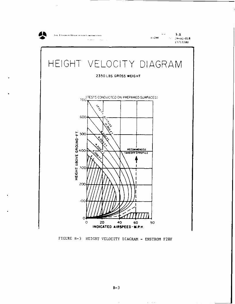
FIGURE B-3 HEIGHT VELOCITY DIAGRAM - ENSTROM F28F
B- 3

Tom Ew..vowla He amoaauq Uiupnsavw... 04" 5.4F-28F iow oo 28-AC-018Ohif 11/17/80
EFFECT OF LOADING ONCHOICE OF H-V ENVELOPE
The H-V curves presented in Figure 5.5 are valid for operations at 2350 lb grossweight for the specific density altitude conditions presented. For operation atother than 2350 lb gross weight, determine the proper H-V curve to be used forthe intended grass weight and density altitude for the flight from the curvespresknted in F yure 5.6 below. For operations aDove 2500 lb grass weight, usethe H-V curves presented in Figure 5.7 in place of Figures 5.6 and 5.5.
Example: (1) A gross weight of 2000 lbs and 3900 ft H would allow the use ofthe sea level envelope. d
(2) A gross weight of 2200 lbs and 4500 ft H dwould require a 2800 ft
curve, to be conservative, use the next higher curve. 4000 ft.12.000
10.000i.
?35GROSSWEIGH (lbM
FIGURE B-'FETOMODN NCOIEO - NEOE -F8
6,000

V-28F atoi'- 2-AC-8
0.1 11/17/80
E[IGHT VELOCITY DIAGRAM
2600 L'JS GROSS WEIGHT
700I'AVOID OPERAIioFJ IN THIS A~iA
600
Soo SAFE 0 PERATINGI AREA
0, Ix N
0 20 40 6z 80 65
Indcalod Attsoved - MPH
FIGURE B-5 HEIGHT VELOCITY DIAGRAM -F28F
B-S

HOW TO USE THE FIGURE RELATED TO HEIGHT - VELOCITY
For an all-up weight above 2150 kg (4720 lb) , the aera to be avoidel isdefined by the three points A, B and C.
Oetermining point B
Point B is fixed and located at a 50 ft (15 m) height for a 30 kt(56 km/h - 35 MPH) velocity.
Determining points C and A
Points C and A are determined at a zero velocity and depend upon the actualweight and pressure - altitude.
- From the pressure - altitude (1), read across to the actual weight (2)- Read vertically down to curves (3) and (4)- From (3) and (4) read across to the height of points C and A
NOTE When points C and A coincide, there is no unsafe area any longer- Example 2000 ft and 2300 kg
C/
4r4/ . ..
7/ 0
-6
• // "I i "
//
ill I = . "B
I II ..... ..7
FIGURE B-6 DETERMINING THE IIEIGIHT VELOCITY - AS 355F

8000 2500.
1000-
2000. -z -
I..... - {500.t} T - 160- 50
.120 J80 - I
-20 -4-
i t "- - -in
10_I /I
0 - -0j! j 0t 0 A . .,
0 10 20 301Kt)
0 20 4'0 0(Km/ih)
FIGURE B-6 DETERMINING THE HEIGHT VELOCITY DIAGRAM - AS 355F (Continued)
*U.S. GOVERNMENT PRINTING OFFICE: 1991--617-297/41012
B-7