
This Book Is Safari Enabled - pearsoncmg.comptgmedia.pearsoncmg.com/images/9780132353748/... ·...
46
Transcript of This Book Is Safari Enabled - pearsoncmg.comptgmedia.pearsoncmg.com/images/9780132353748/... ·...


The authors and publisher have taken care in the preparation of this book, but make no expressed orimplied warranty of any kind and assume no responsibility for errors or omissions. No liability isassumed for incidental or consequential damages in connection with or arising out of the use of theinformation or programs contained herein.
© Copyright 2008 by International Business Machines Corporation. All rights reserved.
Note to U.S. Government Users: Documentation related to restricted right. Use, duplication, ordisclosure is subject to restrictions set forth in GSA ADP Schedule Contract with IBM Corporation.
IBM Press Program Managers: Tara Woodman, Ellice Uffer
Cover design: IBM Corporation
Associate Publisher: Greg Wiegand
Marketing Manager: Kourtnaye Sturgeon
Publicist: Heather Fox
Acquisitions Editor: Katherine Bull
Development Editor: Ginny Bess Munroe
Managing Editor: Kristy Hart
Designer: Alan Clements
Project Editor: Chelsey Marti
Copy Editor: Keith Cline
Indexer: Brad Herriman
Senior Compositor: Gloria Schurick
Proofreader: Water Crest Publishing
Manufacturing Buyer: Dan Uhrig
Published by Pearson plc
Publishing as IBM Press
IBM Press offers excellent discounts on this book when ordered in quantity for bulk purchases orspecial sales, which may include electronic versions and/or custom covers and content particular toyour business, training goals, marketing focus, and branding interests. For more information, pleasecontact:
U.S. Corporate and Government [email protected]
For sales outside the U.S., please contact:
International [email protected].
The following terms are trademarks or registered trademarks of International Business MachinesCorporation in the United States, other countries, or both: IBM, the IBM logo, IBM Press, CICS,Component Business Model, DataPower, developerWorks, IMS, Lotus, MVS, OMEGAMON, Rational,Rational Unified Process, Redbooks, RequisitePro, RUP, Tivoli, Tivoli Enterprise Console, WebSphereand z/OS. Java and all Java-based trademarks are trademarks of Sun Microsystems, Inc. in the UnitedStates, other countries, or both. Microsoft, Windows, Windows NT, and the Windows logo aretrademarks of Microsoft Corporation in the United States, other countries, or both. Linux is aregistered trademark of Linus Torvalds in the United States, other countries, or both. Other company,product, or service names may be trademarks or service marks of others.

This Book Is Safari EnabledThe Safari® Enabled icon on the cover of your favorite technology book means thebook is available through Safari Bookshelf. When you buy this book, you get freeaccess to the online edition for 45 days. Safari Bookshelf is an electronic referencelibrary that lets you easily search thousands of technical books, find code samples,
download chapters, and access technical information whenever and wherever you need it.To gain 45-day Safari Enabled access to this book:
• Go to http://www.awprofessional.com/safarienabled.• Complete the brief registration form.• Enter the coupon code HXLI-NDXM-4LDM-7UMT-LQP8.
If you have difficulty registering on Safari Bookshelf or accessing the online edition, please [email protected].
Library of Congress Cataloging-in-Publication Data
Executing SOA : a practical guide for the service-oriented architect / Norbert Bieberstein ... [et al.]. —1st ed.
p. cm.
Includes index.
ISBN 0-13-235374-1
1. Web services. 2. Computer network architectures. 3. Business enterprises—Computer networks.4. Computer architecture. I. Bieberstein, Norbert.
TK5105.88813.E96 2008
004.6’5—dc22
2008006598
All rights reserved. This publication is protected by copyright, and permission must be obtained fromthe publisher prior to any prohibited reproduction, storage in a retrieval system, or transmission inany form or by any means, electronic, mechanical, photocopying, recording, or likewise. Forinformation regarding permissions, write to:
Pearson Education, IncRights and Contracts Department501 Boylston Street, Suite 900Boston, MA 02116Fax (617) 671 3447
ISBN-13: 978-0-13-235374-8ISBN-10: 0-13-235374-1
Text printed in the United States on recycled paper at R.R. Donnelley in Crawfordsville, Indiana.First printing May 2008
Service-oriented architecture (SOA) is no longer new. Indeed, it suffers from some retrench-ment and backlash as the “hype curve” settles, with many pointing to examples of failedattempts. Why is that? If this direction was so compelling, why are some turning to a degreeof skepticism and outright cynicism? The major reason lies in our collective failure to under-stand that this kind of transition is difficult and requires discipline, in-depth understanding,and active involvement from the business as well as the IT infrastructure. Discipline isneeded in collaborative alignment and cross-group processes that we tend to associate withbroader organizational thinking—not individual, localized “quick fixes” or silos. As a result,many initial attempts fail for a variety of good reasons:
• A failure to establish effective governance or even realize that governance mustchange to establish enduring benefits in delivering shared, useful, and effectiveservices.
• An attempt to introduce a services discipline into organizational silos without dras-tically altering the culture of collaboration and information-process sharing. Thisoversight absolutely results in failure.
• A failure to understand how to integrate new thinking around services into preex-isting technology assets and directions.
• Believing that a single technology or tool will deliver the desired results.• Believing that speed comes from agility, where agility equates to a simplistic view of
“delivering quickly” on isolated, individual projects without regard to organiza-tional life cycle. This is otherwise known as unstructured chaos.
In my view, the fundamental motivation or reason to pursue an SOA is more prevalenttoday than ever before. The pressure to compete with greater speed and innovation as abusiness model remains. The pressure on enterprises, ecosystems, and supply chains to glob-alize is accelerating. The dependency on IT systems to scale businesses constantly grows, andtechnology continues to pervade all facets of commerce and of everyday life.
xv
Foreword
Many of the scale issues in any shift in business models comes from the growing reach andchoice afforded by the ever more ubiquitous Internet. The Internet is changing and evolving.Bandwidth continues to increase, and the resulting network effects are providing opportunityfor new businesses and business models while also wreaking havoc on the existing ones. Allwe have to do is look to everyday examples in the music industry (indeed, in entertainmentas a whole). Telecom service providers (TSPs) are classic examples where vertical integrationof industry and the billing models have been torn asunder by the introduction of pervasiveIP-based services and devices. The interaction of the two (entertainment and TSPs) is evenmore dramatic and has downstream effects on consumer electronics, automotive, and so on.The growing choices and resulting shifts in global supply chains and sourcing affect every-thing from manufactured goods to intellectual property and talent. There is no place to hide.
IT systems are forced to enable or to lead this trend; if not, the associated businesses will fail tocompete and fade into irrelevance. Key to enabling flexibility and scale are the tenets of serv-ice-oriented architectures. As has been said before, there is no magic in SOA. In many ways, itis the evolution of the ever-present and old concept of “modularity” and structural decompo-sition applied to better alignment of IT and business at a global, open scale. However the rawscale issues of modularity and sharing in successful services-based architectures to be deployedon the Internet in support of truly globalized business has never before been attempted.
I experienced this scale issue in transforming Rational® in IBM®. I embarked on trying to useSOA to effect both a cultural and a technical evolution in Rational’s business and Rational’stechnology. The Jazz direction and architecture are prime examples of a shift in strategy thatstems not just from an Internet-based architecture but from a rethinking of both the busi-ness and the technology underlying development tools and platforms. It puts us in a posi-tion to generate new products, evolve from existing ones, and take advantage of emergingbusiness models (pricing and packaging) in delivering value to our customers. In line withthe book, it required a shift in culture, a shift in governance models—organization, tech-nology assumptions, information architectures, and collaboration services. It requiredrethinking the business of software development and modeling it as a series of businessprocesses that need to establish and report through dynamic monitoring of metrics withservices that can be delivered on internets in a globally distributed model. The jury is outyet on whether we have turned vision into execution, but I am convinced now, more thanever, that it was the right thing to do.
In that spirit, I encourage you to view this book as an update that imparts the benefit of exten-sive experience in SOA-based engagements with ourselves and our customers over the pastfour years. The first edition set the stage and brought out many of the key issues and think-ing. This version delves deeply into key issues such as governance, management of services,and especially the challenges of life cycle. It addresses many of the failure issues I highlightedin the beginning of the Foreword. The team that put it together is experienced and has boileddown best practices and delivered a practical and thoughtful roadmap to implementing suc-cessful SOA transformations. Enjoy the ride. After all, if it were easy, anyone could do it!
Daniel SabbahGM, Rational SoftwareIBM Software Group
xvi Foreword
When the programming model shifted from the traditional procedural model tothat of object-orientation, a major paradigm shift occurred in the world of ITdevelopment. The focus was on encapsulating the state and behavior of entities
and calling that encapsulation a class. Instances of a class were called objects, which occu-pied some space in the memory. Object orientation (OO) brought in concepts of inheri-tance, encapsulation, and polymorphism that could be applied to define relationshipsbetween classes. With the prevalence of the use of OO in the programming world, develop-ers and architects started noticing some patterns that can be applied to the usage of OOprinciples to solve similar types of problems. The patterns depicted the deconstruction of aproblem into multiple class entities, together with their interrelationships using the basicconcepts of OO, to provide a solution to the problem. The seminal work in this field wasdone by the Gang of Four authors in the book called Design Patterns: Elements of ReusableObject-Oriented Software. (See the “References” section.) Whereas in OO the first-class con-structs were objects and classes, the next-generation methodology for building softwareapplications was called component-based development (CBD). In CBD, the first-class con-structs were components, where a component was defined by its external specification,which could be used without any knowledge of its internal implementation. As such, thesame external specification could be implemented in different programming language (forexample, Java, C#). The internal implementation of a component may use multiple classesthat collectively provide the implementation of the external specification. The classes coulduse one or more design patterns, thereby leveraging the advantages of OO principles.
In SOA, the main emphasis is on the identification of the right services followed by theirspecification and realization. Although some might argue that object-oriented analysis anddesign (OOAD) techniques can be used as a good starting point for services, its main empha-sis is on microlevel abstractions. Services, on the other hand, are business-aligned entitiesand therefore are at a much higher level of abstraction than are objects and components.
57
Chapter 4
A Methodology forService Modeling andDesign

The main first-class constructs in an SOA are services, service components, and process flows.For the sake of brevity, we refer to process flows as just flows. These are at a level of abstrac-tion that is higher than that of objects, classes, and components. Hence, there needs to bea higher level of modeling and design principles that deal with the first-class constructs ofan SOA. Service-oriented modeling and design is a discipline that provides prescriptive guid-ance about how to effectively design an SOA using services, service components, and flows.Rational Software, now a part of IBM, has provided an extension to Rational Unified Process(RUP) called RUP-SOMA (see the “References” section), which is built on a service-orientedanalysis and design technique developed by IBM called Service Oriented Modeling andArchitecture (SOMA). The rest of this chapter takes you through the SOMA technique andexplains how it helps in the identification, specification, and realization of services, servicecomponents, and flows.
4.1 An SOA Reference Architecture
When defining a service-oriented solution, it makes sense to keep a reference architecture incontext—an architecture that establishes the building blocks of SOA: services, service compo-nents, and flows that collectively support enterprise business processes and the businessgoals. The reference architecture provides characteristics and definitions for each layer andthe relationships between them and assists in the placement of the architectural buildingblocks onto each layer. This layering facilitates the creation of architectural blueprints inSOA and helps in reusability of solutions and assets within an industry and potentiallyacross industry verticals. Figure 4-1 shows a sample logical SOA reference architecture.
58 Chapter 4 • A Methodology for Service Modeling and Design
A.4.1
Governance layer
Information architecture layer
(metadata and business intelligence)
QoS
layer (security, managem
ent,and m
onitoring infrastructure services)
Integration layer (Enterprise S
ervice Bus)
Consumers layer
Business process layerComposition; choreography;business state machines
Services layerAtomic and composite
Service components layer
Operational layer
Channel B2B
Packagedapplication
Customapplication
Service consum
er
application
Service provider
Figure 4-1 Logical view of SOA Reference Architecture
The figure shows a nine-layered architecture with five horizontal layers and four vertical lay-ers. The horizontal layers follow the basic principle of a layered architecture model in which

architecture building blocks (ABB) from layers above can access ABBs from layers below,whereas layers below may not access ABBs from layers above. The vertical layers usually con-tain ABBs that are cross-cutting in nature, which implies that they may be applicable to andused by ABBs in one or more of the horizontal layers. This can also be called a partial lay-ered architecture because any layer above does not need to strictly interact with elementsfrom its immediate lower layer. For example, a specific access channel can directly access aservice rather than needing to go through a business process. The access constraints, how-ever, are dictated by the architectural style, guidelines, and principles that apply to a givenSOA solution. This view of the SOA reference architecture is independent of any specifictechnology implementation, and hence is a logical view. Instances of this logical architec-ture can be developed for a specific platform and technology. Following are definitions ofeach of the layers:
• Layer 1: Operational systems—This layer includes the operational systems thatexist in the current IT environment of the enterprise, supporting business activities.Operational systems include all custom applications, packaged applications, legacysystems, transaction-processing systems, and the various databases.
• Layer 2: Service component layer—Components in this layer conform to the con-tracts defined by services in the services layer. A service component may realize oneor more services. A service component provides an implementation façade thataggregates functionality from multiple, possible disparate, operational systemswhile hiding the integration and access complexities from the service that isexposed to the consumer. The consumer thus is oblivious of the service component,which encapsulates the implementation complexities. The advantage of this façadecomponent comes from the flexibility of changing operational systems withoutaffecting the service definition. The service component provides an enforcementpoint for service realization to ensure quality of service (QoS) and compliance toservice level agreements.
• Layer 3: Services layer—This layer include all the services defined in the enterpriseservice portfolio. The definition of each service, which constitutes both its syntac-tic and semantic information, is defined in this layer. Whereas the syntactic infor-mation is essentially around the operations on each service, the input and outputmessages, and the definition of the service faults, the semantic information isaround the service policies, service management decisions, service access require-ments, and so on. The services are defined in such a way that they are accessible toand invocable by channels and consumers independent of implementation and thetransport protocol. The critical step is the identification of the services using thevarious techniques that can be employed for the same. The methodology that wefocus on in this chapter addresses such identification techniques.
• Layer 4: Business process layer—Business processes depict how the business runs.A business process is an IT representation of the various activities coordinated andcollaborated in an enterprise to perform a specific high-level business function.This layer represents the processes as an orchestration or a composition of looselycoupled services—leveraging the services represented in the services layer. The layeris also responsible for the entire lifecycle management of the processes along with
4.1 An SOA Reference Architecture 59

their orchestration, and choreography. The data and information flow betweensteps within each process is also represented in this layer. Processes represented inthis layer are the connection medium between business requirements and theirmanifestation as IT-level solutions using ABBs from other horizontal and verticallayers in the architecture stack. Users, channels, and B2B partner systems in theconsumer layer uses the business processes in this layer as one of the ways to invokeapplication functionality.
• Layer 5: Consumer layer—This layer depicts the various channels through whichthe IT functions are delivered. The channels can be in the form of different user types(for example, external and internal consumers who access application functionalitythrough access mechanisms like B2B systems, portals, rich clients, and other forms).The goal of this layer is to standardize on the access protocol and data format toenable the quick creation of front ends to the business processes and services exposedfrom the layers below. Some such standards have emerged in the form of portlets,service component architecture (SCA) components, and Web Services for RemotePortlets (WSRP). The adherence to standard mechanisms for developing the presen-tation layer components for the business processes and services helps in providingtemplate solutions in the form of standard architecture patterns, which helps thedeveloper community to adopt common front-end patterns for service consumption.
• Layer 6: Integration layer—This layer provides the capability for service con-sumers to locate service providers and initiate service invocations. Through thethree basic capabilities of mediation, routing, and data and protocol transforma-tion, this layer helps foster a service ecosystem wherein services can communicatewith each other while being a part of a business process. The key nonfunctionalrequirements such as security, latency, and quality of service between adjacent lay-ers in the reference architecture are implemented by the architecture buildingblocks in this layer. The functions of this layer are typically and increasingly beingcollectively defined as the enterprise service bus (ESB). An ESB is a collection ofarchitecture patterns that uses open standards and protocols to implement thethree basic capabilities of this layer and provide a layer of indirection between theservice consumers and the service provider by exposing the services only throughthe ESB. ESB products usually add some specialized features to provide differenti-ated capabilities in the marketplace.The integration capabilities are most commonly used by ABBs residing betweenLayer 2 through Layer 5. As an example, in Layer 5 there can be many consumersaccessing enterprise services through different channel types. Each channel typecan use different protocols—HTML, WML (for mobile users), and Voice XML (forIVR users), to name a few. Each of these protocols and message formats may bepassed through an Extensible Stylesheet Language Transformations (XSLT) enginebefore the actual service is invoked. This XSLT transform is usually an ESB-providedfeature. The beauty of the ESB-based integration layer is that any feature or func-tion that can be exposed in a manner that follows open standards and protocols foraccess can be plugged into the ESB so that it is enabled to take part in a service-based ecosystem. Figure 4-2 depicts a logical view of the ESB.
60 Chapter 4 • A Methodology for Service Modeling and Design
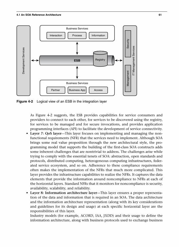
Figure 4-2 Logical view of an ESB in the integration layer
As Figure 4-2 suggests, the ESB provides capabilities for service consumers andproviders to connect to each other, for services to be discovered using the registry,for services to be managed and for secure invocations, and provides applicationprogramming interfaces (API) to facilitate the development of service connectivity.
• Layer 7: QoS layer—This layer focuses on implementing and managing the non-functional requirements (NFR) that the services need to implement. Although SOAbrings some real value proposition through the new architectural style, the pro-gramming model that supports the building of the first-class SOA constructs addssome inherent challenges that are nontrivial to address. The challenges arise whiletrying to comply with the essential tenets of SOA: abstraction, open standards andprotocols, distributed computing, heterogeneous computing infrastructures, feder-ated service ecosystem, and so on. Adherence to these compliance requirementsoften makes the implementation of the NFRs that much more complicated. Thislayer provides the infrastructure capabilities to realize the NFRs. It captures the dataelements that provide the information around noncompliance to NFRs at each ofthe horizontal layers. Standard NFRs that it monitors for noncompliance is security,availability, scalability, and reliability.
• Layer 8: Information architecture layer—This layer ensures a proper representa-tion of the data and information that is required in an SOA. The data architectureand the information architecture representation (along with its key considerationsand guidelines for its design and usage) at each specific horizontal layer are theresponsibilities of this layer. Industry models (for example, ACORD, IAA, JXDD) and their usage to define theinformation architecture, along with business protocols used to exchange business
4.1 An SOA Reference Architecture 61
Interaction Process Information
Business Services
ESB
Partner Business App Access
Business Services
Dev
elop
men
t Ser
vice
s
IT M
anag
emen
t Ser
vice
s
Man
agem
ent
Sec
urity
Registry
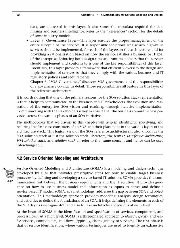
data, are addressed in this layer. It also stores the metadata required for data mining and business intelligence. Refer to the “References” section for the detailsof some industry models.
• Layer 9: Governance layer—This layer ensures the proper management of theentire lifecycle of the services. It is responsible for prioritizing which high-valueservices should be implemented, for each of the layers in the architecture, and forproviding a rationalization based on how the service satisfies a business or IT goalof the enterprise. Enforcing both design-time and runtime policies that the servicesshould implement and conform to is one of the key responsibilities of this layer.Essentially, this layer provides a framework that efficiently oversees the design andimplementation of services so that they comply with the various business and ITregulatory policies and requirements.Chapter 3, “SOA Governance,” discusses SOA governance and the responsibilitiesof a governance council in detail. Those responsibilities all feature in this layer ofthe reference architecture.
It is worth noting that one of the primary reasons for the SOA solution stack representationis that it helps to communicate, to the business and IT stakeholders, the evolution and real-ization of the enterprises SOA vision and roadmap through iterative implementation.Communicating with the stakeholders is key to ensure that the business commitment is per-vasive across the various phases of an SOA initiative.
The methodology that we discuss in this chapter will help in identifying, specifying, andrealizing the first-class constructs of an SOA and their placement in the various layers of thearchitecture stack. This logical view of the SOA reference architecture is also known as theSOA solution stack or just the solution stack. Therefore, the terms SOA reference architecture,SOA solution stack, and solution stack all refer to the same concept and hence can be usedinterchangeably.
4.2 Service Oriented Modeling and Architecture
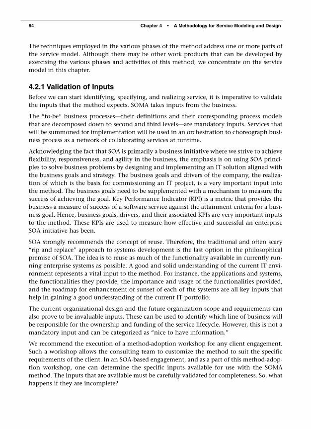
Service Oriented Modeling and Architecture (SOMA) is a modeling and design techniquedeveloped by IBM that provides prescriptive steps for how to enable target businessprocesses by defining and developing a service-based IT solution. SOMA provides the com-munication link between the business requirements and the IT solution. It provides guid-ance on how to use business model and information as inputs to derive and define aservice-based IT model. SOMA, as a methodology, addresses the gap between SOA and objectorientation. This methodology approach provides modeling, analysis, design techniques,and activities to define the foundations of an SOA. It helps defining the elements in each ofthe SOA layers (see Figure 4-2) and also to take architectural decisions at each level.
At the heart of SOMA is the identification and specification of services, components, andprocess flows. At a high level, SOMA is a three-phased approach to identify, specify, and real-ize services, components, and flows (typically, choreography of services). The first phase isthat of service identification, where various techniques are used to identify an exhaustive
62 Chapter 4 • A Methodology for Service Modeling and Design
A.4.2
list of candidate services. The second phase is that of service specification, in which adetailed design of services and components is completed. The realization phase focuses onmaking architectural decisions, justifying the most prudent approach to implement theservices.
SOMA focuses directly on the services, service components, and flows. These SOA constructsreside between Layer 2 and Layer 4 of the architecture stack. However, the activities per-formed as a part of the end-to-end methodology influence the placement of components inthe other layers of the stack. Figure 4-3 illustrates the focus of SOMA as it pertains to thesolution stack.
4.2 Service Oriented Modeling and Architecture 63
Governance
Data A
rchitecture and Business Intelligence
QoS
, Security, M
anagement,
and Monitoring Infrastructure S
ervice
consumers
business processesprocess choreography
servicesatomic and composite
service components
operational systems
JService Portlet WSRP B2B Other
Service consum
erS
ervice provider
SO
MA
Fo
cus
5
1
2
3
4
6 7 8 9
Integration (Enterprise S
ervice Bus A
pproach)
Packagedapplication
Customapplication application
Figure 4-3 The focus of SOMA is on Layer 2 through Layer 4.
One of the main outputs of the SOMA method is a service model. It is recommended that aservice model constitute of the following artifacts about services:
• Service portfolio—List of all the enterprise services• Service hierarchy—A categorization of services into service groups• Service exposure—An analysis and rationalization of which services should be
exposed and which should not• Service dependencies—Representing the dependencies of services on other
services• Service composition—How services take part in compositions to realize business
process flows• Service NFRs—The nonfunctional requirements that a service must comply with• State management—The various types of states that a service should maintain and
implement• Realization decisions—Architectural decisions, for each service, around the most
justified mechanism to implement the service
The techniques employed in the various phases of the method address one or more parts ofthe service model. Although there may be other work products that can be developed byexercising the various phases and activities of this method, we concentrate on the servicemodel in this chapter.
4.2.1 Validation of InputsBefore we can start identifying, specifying, and realizing service, it is imperative to validatethe inputs that the method expects. SOMA takes inputs from the business.
The “to-be” business processes—their definitions and their corresponding process modelsthat are decomposed down to second and third levels—are mandatory inputs. Services thatwill be summoned for implementation will be used in an orchestration to choreograph busi-ness process as a network of collaborating services at runtime.
Acknowledging the fact that SOA is primarily a business initiative where we strive to achieveflexibility, responsiveness, and agility in the business, the emphasis is on using SOA princi-ples to solve business problems by designing and implementing an IT solution aligned withthe business goals and strategy. The business goals and drivers of the company, the realiza-tion of which is the basis for commissioning an IT project, is a very important input intothe method. The business goals need to be supplemented with a mechanism to measure thesuccess of achieving the goal. Key Performance Indicator (KPI) is a metric that provides thebusiness a measure of success of a software service against the attainment criteria for a busi-ness goal. Hence, business goals, drivers, and their associated KPIs are very important inputsto the method. These KPIs are used to measure how effective and successful an enterpriseSOA initiative has been.
SOA strongly recommends the concept of reuse. Therefore, the traditional and often scary“rip and replace” approach to systems development is the last option in the philosophicalpremise of SOA. The idea is to reuse as much of the functionality available in currently run-ning enterprise systems as possible. A good and solid understanding of the current IT envi-ronment represents a vital input to the method. For instance, the applications and systems,the functionalities they provide, the importance and usage of the functionalities provided,and the roadmap for enhancement or sunset of each of the systems are all key inputs thathelp in gaining a good understanding of the current IT portfolio.
The current organizational design and the future organization scope and requirements canalso prove to be invaluable inputs. These can be used to identify which line of business willbe responsible for the ownership and funding of the service lifecycle. However, this is not amandatory input and can be categorized as “nice to have information.”
We recommend the execution of a method-adoption workshop for any client engagement.Such a workshop allows the consulting team to customize the method to suit the specificrequirements of the client. In an SOA-based engagement, and as a part of this method-adop-tion workshop, one can determine the specific inputs available for use with the SOMAmethod. The inputs that are available must be carefully validated for completeness. So, whathappens if they are incomplete?
64 Chapter 4 • A Methodology for Service Modeling and Design
The first thing to do is to assess the gaps between the required and the available informa-tion, and then a gap-mitigation plan needs to be put in place. A part of the recommendedapproach is to perform further interview sessions with the stakeholders and subject matterexperts (SME) and use that information gathered therein to incorporate the missing infor-mation. We also recommend documenting customer pain points and use them to define thecustomer requirements, business drivers, and priorities. These are by no means the only twoways to address gaps between available and required inputs, and the IT team might have itsown gap-mitigation plan as it suits the current customer scenario.
If the mandatory inputs are not available, however, a commitment needs to be made by thebusiness stakeholders to make them available to the degree of completeness as requested bythe IT team.
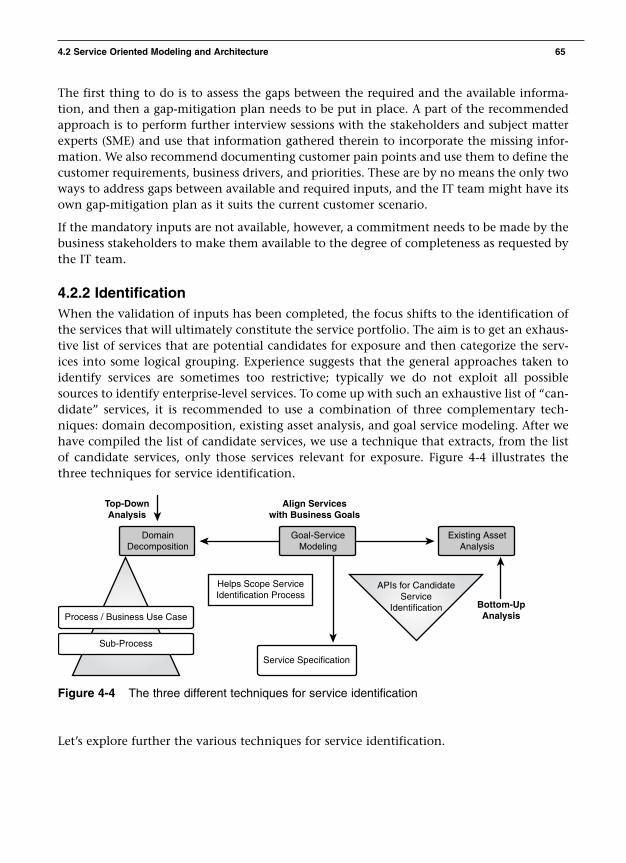
4.2.2 IdentificationWhen the validation of inputs has been completed, the focus shifts to the identification ofthe services that will ultimately constitute the service portfolio. The aim is to get an exhaus-tive list of services that are potential candidates for exposure and then categorize the serv-ices into some logical grouping. Experience suggests that the general approaches taken toidentify services are sometimes too restrictive; typically we do not exploit all possiblesources to identify enterprise-level services. To come up with such an exhaustive list of “can-didate” services, it is recommended to use a combination of three complementary tech-niques: domain decomposition, existing asset analysis, and goal service modeling. After wehave compiled the list of candidate services, we use a technique that extracts, from the listof candidate services, only those services relevant for exposure. Figure 4-4 illustrates thethree techniques for service identification.
4.2 Service Oriented Modeling and Architecture 65
DomainDecomposition
Goal-ServiceModeling
Service Specification
Existing AssetAnalysis
Helps Scope ServiceIdentification Process
APIs for CandidateService
Identification Bottom-UpAnalysis
Top-DownAnalysis
Align Serviceswith Business Goals
Process / Business Use Case
Sub-Process
Figure 4-4 The three different techniques for service identification
Let’s explore further the various techniques for service identification.

4.2.1.1 Domain DecompositionThis is a top-down technique that involves the decomposition of the business domain intoits functional areas and subsystems, including the decomposition of its business processesinto subprocesses and high-level business use cases. These use cases are often good candidatesfor business services exposed at the edge of the enterprise, or for those used within theboundaries of the enterprise across lines of business. Apart from identifying candidate serv-ices, this technique helps to identify functional areas that identify boundaries for subsystems.
This technique includes one step called functional area analysis (FAA). In FAA, we decom-pose the business domains into logical cohesive functional units and name each unit as afunctional area. The resultant set of functional areas provides a modular view of the busi-ness and forms the basis of IT subsystem identification, nomenclature, and design. It is notnecessary for FAA to be done as a part of SOMA because it can leverage similar work thatcould have been done as a part of any other project initiative in the same enterprise. Theidentification of functional areas assists in their usage in service categorization, wherein theidentified candidate services can be categorized using the functional areas. The “ServiceHierarchy” section of the service model work product is a formalization of the categoriza-tion of services.
FAA usually falls under the expertise realm of business analysts and domain experts. Onecan start with a base set of functional areas, but if and when services are identified and startto be grouped using the functional areas, one can refactor the existing functional areas sothat they make sense from a service grouping standpoint. The key point we are trying tomake here is that functional areas can be refactored to suit the proper grouping to services.
The next step in this technique is called process decomposition. In process decomposition,we decompose business processes into its constituent subprocesses and further into moreatomic activities or tasks. The resultant process model depicts both the business-level andIT-level flow of events that realize a business process. It also forms the basis of candidateservice identification. A process is a group of logically related activities that use the resourcesof the organization to provide defined results in support of the organization’s objectives.Process models describe the work that an organization is involved in and the behavior ofsystems the organization uses. Each business process in the scope of the business or IT trans-formation is decomposed into subprocesses and further into leaf-level subprocesses. Eachactivity in the resultant process model or process breakdown tree is considered a candidatefor service exposure. Hence, each is added to a list called the service portfolio. At this point,the service portfolio consists of all the subprocesses, activities, and tasks from the processmodel definitions for every single process. The “Service Portfolio” section of the servicemodel work product is the recipient of the list of candidate services that are identified in thisstep.
Decomposition of processes into its activities and tasks also assists in identifying common-alities and variations between multiple business processes. The common activities or sub-processes provide good candidates for services while the points of variability enable thedesign of the system in a way that it fosters design resiliency and makes the system moreadaptive to incorporate future changes. Variations in a system are usually identified across
66 Chapter 4 • A Methodology for Service Modeling and Design

three aspects: structures, processes, and rules. Externalizing these variability points enablesconfigurable injection of flexibility into system design. Variations may also suggest newservices based on types, processes, and rules.
4.2.1.2 Existing Asset AnalysisExisting asset analysis is a bottom-up approach in which we examine assets such as existingcustom applications, packaged applications and industry models to determine what can beleveraged to realize service functionality. This analysis is also designed to uncover any serv-ices that may have been missed through process decomposition. While you are analyzingexisting legacy and custom applications, we recommend performing a coarse-grained map-ping in which you map business functionality in the portfolio of existing applications to thebusiness processes and determine which step (as identified through domain decompositionin Section 4.2.1.1) in the process can be potentially realized by some functionality in exist-ing applications. We do not recommend performing a fine-grained mapping to specifictransactions and batch processes within legacy application at this stage.
During the coarse-grained mapping activity, a detailed understanding of the application’sstate and quality is obtained that will allow the assessment of technical risks associated withthe services that are going to be realized by the existing system functionality. For the appli-cations that have such technical risks associated with their usage for service implementa-tion, we recommend scoping some technical prototypes to test things like basicconnectivity, protocol issues, data structures and formats, and so on. This prototyping willhelp mitigate the project risks that might otherwise crop up during the later stages, forexample, during implementation.
So, with this technique, we can not only start thinking about service realizations using exist-ing assets but also identify new services. These new services will be added to the service port-folio. At this point, the service portfolio consists of potential services derived from both atop-down and a bottom-up approach.
4.2.1.3 Goal Service ModelingGoal service modeling (GSM) is the third of the three techniques and is used to validate andunearth other services not captured by either top-down or bottom-up service identificationapproaches. It ensures that key services have not been missed. GSM provides the key linkbetween the business goals and IT through the traceability of services directly to a businessgoal. The attainment of the goal, through the supporting service, is measured through theKPIs and its metrics that were documented as a part of the inputs from the business. GSMalso ensures that stakeholder involvement and accountability is maintained through theirconsent on the business goals that needs to be achieved. Services directly linked to the busi-ness goals would then have a higher probability of being prioritized and funded for subse-quent design and implementation. It is worthwhile to point out that GSM may be used asa scoping mechanism that assists in defining the scope of a project by focusing deeper intothe problem domain. A problem domain is often too large to be tackled in one iteration andhence narrowing down and identifying an area that provides the highest impact (by realiz-ing one or more business goals) to the business in a reasonable and acceptable timeframe is
4.2 Service Oriented Modeling and Architecture 67
a recommended way of scoping a project initiative. Once the scope is defined around a busi-ness goal, not only can services be identified through the GSM technique but also the top-down (domain decomposition) and bottom-up (existing asset analysis) techniques may beperformed on the given scope of the project.
Identifying business goals is a nontrivial task. It is not uncommon for clients to be grapplingfor ways to articulate their real business goals. SOA architects are not the ideal consultantswho can be of much help to the business people. The business analysts and SMEs are theones who come to the rescue, helping the clients to clearly articulate their business goals.
The business goals are usually stated in a way that are too lofty and at a very high level. Itis difficult and often impossible to try to identify and associate a service to these lofty goals.The recommended approach is to work closely with the business and domain SMEs todecompose the goals into subgoals, and keep decomposing until the point that a subgoal isactionable. Actionable here means the attainment of what I call as the “Aha!” factor—that Ican identify an IT function that I can use to realize this subgoal. Hence, each business goalis usually decomposed into subgoals, and then services are identified that can realize them.This approach differs radically from the top-down and bottom-up techniques, and thereforeyou have a high potential of discovering new services. These new services are added back tothe service portfolio. Some of the discovered services can be found to be already present inthe existing service portfolio. This is a good thing, a validation step that ascertains that morethan one technique for service identification has identified the same service!
So, what do we achieve in the service identification phase?
• We have taken a three-pronged approach to identify candidate services.• Each identified candidate service is added to the service portfolio.• FAA is performed or leveraged to provide a mechanism to group services—the serv-
ice hierarchy.• The service grouping may be iteratively refactored to provide the best categoriza-
tion of services.• For functionality in existing applications identified for use to realize service imple-
mentations, a technical assessment is performed to assess the viability of reusingthe existing application for service implementation.
From a service model standpoint, what have we addressed?
• We are able to provide a service portfolio of candidate services. • We categorized the services into a service hierarchy or grouping.
With this, we move on to the second phase in the method: specification of services.
4.2.3 SpecificationThe specification phase helps design the details of the three first-class constructs of SOA:services, service components, and flows. It uses a combination of three high-level activitiesto determine which services to expose, provides a detailed specification for the exposed serv-ices, and specifies the flows (processes) and service components. The three activities are
68 Chapter 4 • A Methodology for Service Modeling and Design

called service specification, subsystem analysis, and component specification. From a serv-ice model work product standpoint, this phase provides the most content: The service expo-sure, service dependencies, service composition, service NFRs, service messages, and statemanagement are all addressed in this phase. The rest of this section focuses on the threeactivities.
4.2.3.1 Service SpecificationService specification defines the dependencies, composition, exposure decisions, messages,QoS constraints, and decisions regarding the management of state within a service.
The first task concerns service exposure. The service portfolio had an exhaustive list of serv-ices obtained through the three techniques that we used for service identification. It is easyto comprehend that this list may contain too many candidate services; not all of them areat the right level of granularity to be exposed as services. Some of the service candidates maybe too coarse grained and might actually be more like business processes or subprocessesrather than individual services (for example, some of the process elements derived from thefirst level of process decomposition), whereas some others may be too fine-grained IT func-tions (for example, the process elements in the lowest level of process decomposition andsome of the existing system functionality). Deciding to expose the entire list of candidateservices is a perfect recipe for following a perfect antipattern in SOA—the service prolifera-tion syndrome (a phenomenon we want to avoid). Some economic and practical consider-ations limit the exposure of all candidate services. A cost is associated with every servicechosen for exposure. The funding of the entire service lifecycle, the governance factoraround service lifecycle management, and the added underlying infrastructure requirementsto support security, scalability, performance, and other nonfunctional requirements make itimpractical to follow the rules of economies of scale when it comes to exposing all candi-date services.
Based on these premises, we recommend a service litmus test. The test consists of specificcriteria applied to the candidate services. Only those services that meet the criteria are cho-sen for service exposure. The method provides an initial set of test criteria in the followingform:
1. Business alignment—A service must be business aligned. If a service is not, in someshape or form, traceable back to a business goal, it may not be an ideal candidateto be chosen for exposure.
2. Composability—Tests the ability of a service to be used in a context entirely dif-ferent from the one from which the service was originally identified. A serviceshould be able to participate in multiple business processes without compromisingthe NFR compliance requirements for the process.
3. Feasibility of implementation—Tests the technical feasibility of implementing theservice in a cost- and time-effective manner. Practical considerations limit overlycomplex services to be commissioned for implementation.
4. Redundancy elimination—Tests whether the service can be used within allprocesses and applications where its function is required.
4.2 Service Oriented Modeling and Architecture 69

This method by no means enforces these four litmus tests and recommends defining litmustest criteria taking the client environment, goals, and other relevant and pertinent client-specific factors into account. The most important point here is that some form of an elimi-nation criterion needs to be defined that will allow the prioritization of services for exposureconsideration. It is also recommended to provide a justification for the services that failedthe litmus test for exposure. This justification, when documented, provides crucial infor-mation which becomes vital when the failed services might be revisited later in the scope ofanother SOA initiative in the same enterprise. It is quite possible that the business goals,client prerogatives, and other factors as applicable during subsequent projects might exposea service that might not have passed the exposure tests during the current scope!
Now that a filtered list of services has been determined, the services chosen for exposureconstitute the refined service portfolio. Each service in this portfolio now needs to be pro-vided with detailed specification. The first specification activity is to identify servicedependencies.
Services are ideally dependent on other exposed services. Although in an ideal world of SOAeverything is a service, in reality we find that services are more frequently dependent onunderlying IT components. This dependency happens typically in situations where QoSrequirements such as performance and availability tend to push SOA architects to design aservice to be hardwired to one more technology-specific component. A service-to-servicedependency is called a processing dependency because a service is dependent on one ormore services only in the context of a given business process. Sometimes however, strictnonfunctional requirements mandate that services are more tightly coupled in theirdependency on finer grained IT components. This type of dependency is often categorizedas a functional dependency. Categorizing service dependencies into processing and func-tional groupings provides key architectural and design considerations for service imple-mentation. Figure 4-5 provides an example of the two types of dependencies.
70 Chapter 4 • A Methodology for Service Modeling and Design
Create RentalAgreement
Get CleanVehicle on Lot
CreateReservation
Make Reservation
ProcessingFunctional
1.1ReserveVehicle
J2EEComponent
1.1.2Make
Reservation
1.1.1CheckRates
SAPDB
Figure 4-5 The two general types of service dependencies
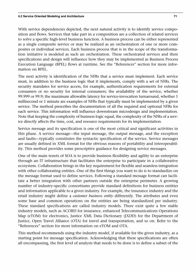
With service dependencies depicted, the next natural activity is to identify service compo-sition and flows. Services that take part in a composition are a collection of related servicesto solve a specific high-level business function. A business process can be either representedas a single composite service or may be realized as an orchestration of one or more com-posites or individual services. Each business process that is in the scope of the transforma-tion initiative is modeled as such an orchestration. These orchestrated services and theirspecifications and design will influence how they may be implemented as Business ProcessExecution Language (BPEL) flows at runtime. See the “References” section for more infor-mation on BPEL.
The next activity is identification of the NFRs that a service must implement. Each servicemust, in addition to the business logic that it implements, comply with a set of NFRs. Thesecurity mandates for service access, for example, authentication requirements for externalconsumers or no security for internal consumers; the availability of the service, whether99.999 or 99.9; the maximum allowable latency for service-invocation turnaround, whether 1millisecond or 1 minute are examples of NFRs that typically must be implemented by a givenservice. The method prescribes the documentation of all the required and optional NFRs foreach service. This information will influence downstream microdesign and implementation.Note that keeping the complexity of business logic equal, the complexity of the NFRs of a serv-ice directly affects the time, cost, and resource requirements for its implementation.
Service message and its specification is one of the most critical and significant activities inthis phase. A service message—the input message, the output message, and the exceptionand faults—typically constitutes the syntactic specification of the service. Service messagesare usually defined in XML format for the obvious reasons of portability and interoperabil-ity. This method provides some prescriptive guidance for designing service messages.
One of the main tenets of SOA is to provide business flexibility and agility to an enterprisethrough an IT infrastructure that facilitates the enterprise to participate in a collaborativeecosystem. Collaboration brings in the key requirement for flexible and seamless integrationwith other collaborating entities. One of the first things you want to do is to standardize onthe message format used to define services. Following a standard message format can facili-tate a better integration with other partners outside the enterprise perimeter. A growingnumber of industry-specific consortiums provide standard definitions for business entitiesand information applicable to a given industry. For example, the insurance industry and theretail industry might define a customer business entity differently. The attributes and evensome base and common operations on the entities are being standardized per industry.These standard specifications are called industry models. There exist quite a few stableindustry models, such as ACORD for insurance, enhanced Telecommunications OperationsMap (eTOM) for electronics, Justice XML Data Dictionary (JXDD) for the Department ofJustice, Open Travel Alliance (OTA) for travel and transportation, and so on. Refer to the“References” section for more information on eTOM and OTA.
This method recommends using the industry model, if available for the given industry, as astarting point for message specification. Acknowledging that these specifications are oftenall encompassing, the first level of analysis that needs to be done is to define a subset of the
4.2 Service Oriented Modeling and Architecture 71

industry model artifacts that is applicable to the client wherein the SOA project is beingundertaken. This subset of the industry model can be the base specifications. In more casesthan not, there will be a need to add some specific extensions to the base specifications thatincorporates client-specific requirements. The base specifications together with the exten-sions constitute what we call the Enterprise Message Format (EMF). Defining the EMF is thefirst step toward service interoperability. Sometimes, a version or a flavor of an EMF mayalready be present with the client. If so, it needs to be analyzed, validated, and enhanced tosupport the new and upcoming requirements. The input and output message elements mustbe compliant with the EMF. The EMF is also a perfect starting point to define the EnterpriseInformation Model (EIM) and it also influences the Logical Data Model (LDM), both ofwhich, although are not necessarily a part of SOA, are mandatory architectural constructs inany enterprise application development.
NOTE
Note that the domain of information architecture plays a very importantrole in SOA. The data translation requirements together with informa-tion architecture that models the data and information flow from theconsumer, through all the layers of the architecture stack right down tothe operational systems layer falls under the domain of the Integrationand Data architecture layers in the SOA reference architecture.
The amount of work that goes into the definition of the EMF and subsequently into servicemessage specifications is often underestimated and becomes the widest chasm to bridge.Keep in mind that service message specification is closely, if not tightly, linked with thedesign of the information model and the data models and therefore not a trivial work effort.
Get your EMF well designed and documented; it will have a positive impact on downstreamdesign and specification activities.
The last major activity focuses on analysis of the state management requirements for a serv-ice and its operations. As a general design rule, the business logic implemented by a serviceshould not include state-specific logic.
However, requirements often mandate that some services address some state requirements.The most commonly occurring types of state are transactional state, functional state, andsecurity state. Transaction state is required to support transactions spanning multiple mes-sages. If an atomic transaction must include the results of multiple business actions pre-formed as a result of multiple messages from a service requestor to a service provider, thestate of the transaction must be maintained until all the messages involved in the transac-tion are completed and the transaction is committed or rolled back.
Security state addresses how the identity of a consumer may be verified. In a stateless sce-nario, the client is authenticated each time a message is received. In a stateful scenario, atoken is typically passed in the message sent by the consumer.
Functional state refers to state that must be maintained between messages while a businessaction is accomplished.
72 Chapter 4 • A Methodology for Service Modeling and Design
We must account for how the specific state requirements must be managed. Sometimes, ITtechnology components influence how state can be managed. For example, a security statecan be managed by a product such as IBM Tivoli Access Manager (see the “References” sec-tion of Chapter 6 for more information), and the transactional state requirements betweenmultiple service invocations in a business process may be managed by a BPEL engine.Hence, the documentation of the specific state requirements for each service is imperative.Keep in mind that during service realization, we can come up with the right architecturaldecisions justifying the best mechanism to implement the state management requirements.So, document them here!
This is just the first major activity during the specification phase; we have two more areasto address. Before we move on, however, we want to mention that all six recommendedactivities that we discussed as a part of this technique are iterative in nature and we will,depending on the scope and complexity of the project, need to run through this techniquemultiple times until we get a refined and robust specification of services at this level.
4.2.3.2 Subsystem AnalysisJust like functional areas provide a logical grouping of a business domain, an IT subsystemis a semantically meaningful grouping of logically cohesive IT artifacts, which are in theform of components and classes. When a functional area is too large to grasp, it is brokendown into these logical units called subsystems. Although this decomposition can be donetop down or bottom up, the method recommends a top-down approach.
A subsystem consists of three types of components: service components, functional com-ponents, and technical components. It is the job of the SOA architect to identify a logicalgrouping of services that can be implemented together by a team that has specific domainknowledge in the area. Subsystem analysis and identification is nothing special to SOA, andit has been practiced from the days of OO; therefore, I call it “architecture as usual” (AAU)work. Let’s focus now on the constituents of a subsystem and how to identify them.
A functional component is an IT component that encapsulates and supplies a single type ofbusiness functionality. For example, any customer-related business logic and IT APIs can beencapsulated in a single functional component called, for example, CustomerManager.
A technical component is an IT component that provides generic functionality such asauthentication, error handling, and auditing. Their implementation is usually more closelytied with the technology platform that is used.
A service component is an IT component built as a coarse-grained façade on top of morefocused and finer-grained functional and technical components. Think of it as a centralcomponent in a mediator pattern. A service is usually aligned to a high-level business func-tion. For this business function to be implemented, it might need to call finer-grained ITAPIs on some functional and technical components. Let’s consider an example in context.Suppose a service is to provide “details of the last reserved vehicle for a customer.” Thisrequirement will typically necessitate a call to a CustomerManager component to “retrievethe customer profile” information, use some business logic to pick the relevant customerdetails from the returned result, and then invoke a VehicleManager component to “retrieve
4.2 Service Oriented Modeling and Architecture 73

the current reserved vehicle” for the given customer. In the process, it may invoke a tech-nical component called AuditManager to log the service request. Neither theCustomerManager nor the VehicleManager nor the AuditManager has the business logic tocontrol this microflow of steps. This control of the microflow, which component to invokeand in which sequence to realize the service request, is the responsibility of the service com-ponent. The service component can be designed to conform to the specifications of servicecomponent architecture (SCA). See Chapter 6, “Realization of Services,” for detailed treat-ment of SCA.
For illustrative purposes only, Figure 4-6 depicts how subsystems are related to service, func-tional, and technical components.
74 Chapter 4 • A Methodology for Service Modeling and Design
«Technical Component»Logging
«Functional Component»Location
«Functional Component»Customer
«Functional Component»Rating
«Technical ComponentEJB Services
«Service Component»Reservation
«Subsystem»Reservation
«Functional Component»Vehicle
Figure 4-6 The relationship between a subsystem and its constituent service, functional, andtechnical components
Identifying the various subsystems followed by the derivation of the service componentsand its constituent functional and technical components that together define a subsystemis the crux of this major step of subsystem analysis.
4.2.3.3 Component SpecificationFrom here on, it is AAU work! There is nothing very special about SOA that we would do.Providing the detailed microlevel design is the focus of this step (that is, the software modelin terms of class diagrams, sequence diagrams, and so on). Each service component identi-fied and designed at a high level in the preceding step is further elaborated into a muchmore detailed treatment. Some typical microdesign steps that apply to a service componentare the following:

1. Identify component characteristics, including component attribute and operationstogether with the policies and rules that they implement.
2. Identify events and messages that the components must sense and respond as atriggering mechanism. Incoming and outgoing component messages are also spec-ified.
3. Identify internal component flow (representing the internal flow of control withinthe service component and which can be represented as a sequence or collabora-tion diagram).
4. Create component class diagrams, which are class models that show the static rela-tionships between the functional and technical components.
Similar types of microdesign activities must be performed for each of the functional andtechnical components so that they are designed and specified to an adequate and unam-biguous level of detail to be comfortably handed over to the implementation team for con-verting into working code. Because these are AAU activities, they are not covered in anyfurther detail in this chapter.
Phew! That was a long section, but we did cover a lot of ground.
Okay, so what did we achieve in the service specification phase?
We were able to filter out only those services that are perfect candidates for exposure, andwe did that by applying the service litmus test.
For each of the services tagged for exposure, we provided prescriptive guidance on how todesign (at a macro level) a full specification for them, including the following:
• How services are dependent on each other (service dependencies)• How services are orchestrated together to form composites that enable business
processes (flows) (service compositions)• Identifying and documenting the nonfunctional requirements that each service
must implement and comply with (service NFRs)• Detailed specification of the service messages (service message specification)• Identifying and documenting the state requirements for each service (service state
management)
While developing service message specifications, we acknowledged how these specificationstie in with and influence the information architecture, the integration architecture, and thedata architecture of the system. Services are not the only SOA construct that we designed inthis phase of SOMA. The processes were further elaborated and their flows were representedas an orchestration of services and IT components. The service component was alsodesigned using their constituent functional and technical components.
From a service model standpoint, what have we achieved?
• Provided a service exposure rationale• Addressed service dependencies• Addressed service compositions and how they help in realizing process flows
4.2 Service Oriented Modeling and Architecture 75

• Emphasized the need to document service NFRs• Addressed the recommended approach to define service messages• Explained why it’s necessary to document state management
Having achieved this, we move on to the third and last phase in this method: realizationdecisions for services.
4.2.3.4 Realization for ServicesThe method in its first two phases not only demonstrated how to use a three-prongedapproach for service identification but they also offered guidance about how to providedetailed specification for the services, service components, and process flows. The main focusof the method in this phase is to provide guidance about how to take architectural decisionsthat facilitate service realization. It is important to note that SOMA does not, at this point intime, address the actual implementation of services; instead, it provides enough informationand detail so that an SOA implementation phase can just concentrate on the developmentand implementation of the services. Implementation is the phase wherein a specific tech-nology, programming language and platform is chosen and used to transform the designspecifications and the realization recipes and patterns into executable code.
This phase has three major activities: component allocation to layers, technical feasibilityanalysis, and realization decisions. The rest of this section focuses on these three majoractivities.
4.2.3.5 Component Allocation to LayersSo far, this method has identified services, process flows, service components, functionalcomponents, and technical components. It also argued that technical components belongto a genre of components that do not directly provide business functionality but insteadfocus on delivering infrastructure functionalities that might be used by multiple functionaland technical components. Keeping the solution stack in mind, we want to provide archi-tectural recipes to allocate the SOA artifacts that we have identified, to the pertinent layersin the solution stack.
The service components and the functional components are all allocated to Layer 2 in thestack. The services, both atomic and composite, are allocated to Layer 3 in the stack. Theprocess flows orchestrated using services from Layer 3 and functional and technical com-ponents from Layer 2, are allocated to Layer 4 of the stack. Technical components are of dif-ferent types. There can be technical components that encapsulate a persistence frameworkor a data access layer. This type of technical component is usually allocated to Layer 8 (thedata architecture layer). Some technical components encapsulate event management func-tionality, whereas others might provide queue management functionality, and some mayencapsulate transaction management features. These types of components are allocated toLayer 6 (the integration layer). There can be other types of technical components, such ascache management, permissions management, audit management, and so forth. Thesetypes of components, which usually assist in complying with QoS requirements, are usuallyallocated to Layer 7 (the QoS layer). As you can see, based on the characteristics of each layerin the reference architecture, the method assists us to map the various types of software arti-facts to the layers.
76 Chapter 4 • A Methodology for Service Modeling and Design

Without paying specific attention to the names of the components, specifically betweenLayers 1 and 4, Figure 4-7 depicts how different types of software building blocks, which themethod assists us in identifying, are allocated to each layer in the solution stack.
4.2 Service Oriented Modeling and Architecture 77
Consumer Layer
BusinessProcess
Layer
Rent Vehicle ProcessCheck out Vehicle
Reserve Vehicle
CreateReservation
ModifyReservation
CancelReservation
CustomerFunctional
Component
VehicleFunctionalComponent
Transformation
RatingFunctional
Component
DisplayReservation
RateShop
ReservationService Component
OIA-XML
ServicesLayer
ServiceComponent
Layer
OperationSystems
Layer
CreateReservation
ModifyReservation
IMS DB
MQ IMS Bridge
IMS Transactions
CancelReservation
DisplayReservation
RateShop
IMF FixedFormat Data
Translator
QueueManagementComponent
EventNotificationComponent
TransactionManagementComponent
SessionManagement
DebuggingFramework
ConfigurationFramework
PersistenceFramework
PersistenceComponent
Data AccessComponent
Gov
erna
nce
Dat
a A
rchi
tect
ure
Sec
urity
, QO
S,
Ser
vice
Man
agem
ent
AuditComponent
LogComponent
PermissionsComponent
LoggingFramework
Figure 4-7 Allocation of software artifacts on the layers of the SOA reference architecture
4.2.3.6 Component Allocation to Layers—Technical Feasibility AnalysisTechnical feasibility takes input primarily from existing asset analysis and takes into accountthe services portfolio defined during service specification. The main focus of this activity isto perform a detailed analysis of existing systems to evaluate how much of the existing tech-nology-specific implementation can be leveraged to realize the services. This activity, as isthe SOMA method itself, is primarily iterative in nature, and it can be started as early as dur-ing the EAA technique during service identification. The functionality, along with the trans-actions identified during the early stages of service identification, needs to be validated forfeasibility for componentization. This type of feasibility analysis results in architectural deci-sions for either the functional or operational architecture of the system. This is the step inthe method where the deep-dive technical analysis of leveraging existing system function-ality is actually formalized. You can do as much service specification as you want, but if youdo not provide deep insight into the implementation of the service, ably supported by itsjustification, there still remains that proverbial gap between where architects hand off thedesign and where developers start with the exact knowledge on what to implement!
Let’s consider an example of assessing the feasibility of using legacy system functionality.We must consider many technology aspects of legacy systems when looking to reuse suchan existing asset for service realization. Some notable examples include the following:
• Exception handling in legacy systems is typically in the form of program termina-tion. This might not be acceptable in a real-time SOA-based system.
• Authentication and authorization are often built in to the legacy application codeusing proprietary technologies and protocols. If legacy functionalities protected viasecurity credentials are considered for reuse, there needs to be a mechanism to inte-grate the embedded security credentials in a federated environment. Externalizingthe legacy security credentials might raise technological issues that will have to beaddressed.
• The typical nightly batch processes for data synchronization or request submissionmay just be too infrequent to be used in real-time scenarios. In such cases, thelegacy processing system might need to be amended; in extreme cases, the processmight prove unusable.
These examples provide a snippet of the challenges that must be addressed when consider-ing the reuse of existing systems and their functionality. Technical feasibility analysisaddresses these types of issues by taking architectural decisions and justifying them for con-sideration.
4.2.3.7 Realization DecisionsThe technical feasibility analysis has a significant influence on how services ought to berealized in the best possible manner. Although technical feasibility analysis is initiated veryearly in the identification phase of the method and is performed throughout the variousphases, considering all the various design and implementation alternatives, this step for-malizes the final realization decision for each service and provides justification for thechoice. This justification is a key step in the process and helps in maintenance and enhance-ment of the system in the years to come. The same realization alternatives could well be re-analyzed during enhancement of the system a few years down the road; and while doing so,the then-available technology might justify a different alternative as better suited. Thus, thesnapshot in time of the architectural justification often proves invaluable.
In general, this method recommends considering six different high-level realization alter-natives, as follows:
1. Integrate—Wrap existing legacy applications with SOA technologies and provide aservice façade using open standards and protocols, for seamless integration into anSOA. Adapter technology is typically suited for this purpose.
2. Transform—Transform parts of legacy applications and expose them. This mightinvolve the extraction of business rules or policies and rewriting the code in a mod-ern SOA-aware programming language. This often falls under the discipline oflegacy modernization.
3. Buy—Purchase products from independent service vendors (ISV) who provide out-of-the-box functionality that are exposed as services. Note that this option oftenresults in a classic SOA antipattern in which the features of the ISV product oftendictate the requirements of an enterprise. So do not fall into this trap and only eval-uate the ISV functionality in the context of the project requirements.
78 Chapter 4 • A Methodology for Service Modeling and Design

4. Build—Build applications following the principles and best practices of SOA. Thisis often called the domain of custom application development.
5. Subscribe—Subscribe to external vendors who provide services that meet or exceedspecific business functional requirements. Various SOA vendors are trying to find aniche in the market where they can specialize in a specific type of offering. Creditcard authorization service is a classic example. Rarely would we see any enterprisedeveloping this functionality indigenously. Instead, they subscribe to the best serv-ice provider that suits their needs.
6. Outsource—Outsource an entire part of the organization’s functions to a thirdparty. This is not yet considered mainstream because SOA is still undergoing somecritical phases in its maturity and adoption. However, there are companies that spe-cialize in, say, HR operations, and we have started seeing big corporations out-sourcing an entire department. These third parties will provide services that needto be seamlessly integrated with the enterprise business processes.
This is what realization decisions help us achieve: a justification of the implementationmechanism for the services in the services portfolio.
So, what did we achieve in the realization phase?
• Understood how to allocate the various software building blocks onto the layers ofthe solution stack.
• Appreciated the justification to perform a detailed technical feasibility analysisbefore using existing legacy functionality for service realization.
• Identified the various options available for service realization.
And from a service model standpoint, what have we addressed?
• We were able to provide realization decisions for services.
This marks the completion of the three phases of the SOMA method. By now, I hope youcan appreciate why a service-oriented analysis and design method, like SOMA, is required inany SOA-based initiative. The treatment provided here has hopefully demonstrated howSOMA is built on top of OOAD, while adding modeling and design techniques specific toSOA.
4.2.4 Using SOMAThe language of SOMA is crisp, clear, and very much focused on, providing a methodologyto solve the challenges the IT community faces regarding service-oriented design. However,it is important to keep in mind that tools are integral to processes or methods, and a well-articulated method drives the development of tools in support of them. Rational UnifiedProcess (RUP) has extended its process technique to incorporate service-oriented design, andit has used the SOMA method as the basis for its extension. This method extension is avail-able as a plug-in in a product from Rational Software called the Rational Method Composer(see the “References” section).
4.2 Service Oriented Modeling and Architecture 79

SOMA method artifacts can also be expressed as a platform-independent model. Think ofSOMA as providing a meta-language that helps in defining a service model. This model rep-resentation, defining not only the SOA constructs but also the relationships and constraintsbetween them, is called the meta-model for SOMA. Any design tool that can implement theSOMA meta-model will be able to provide a tooling environment for service-oriented mod-eling and design based on the SOMA method. Although we do not provide the entire meta-model here, we do offer hints about how to develop one.
Hint: A business domain can be decomposed into one or more functional areas. A functionalarea can be decomposed into one or more subsystems. A subsystem contains one or more serv-ice components. A service component uses one or more functional components and technical com-ponents. If you try to enlist all the various constructs of SOMA and then model relationshipsbetween them, together with constraints on the relationships, you will be able to create theSOMA meta-model. It is then just a matter of implementing the meta-model in a softwaremodeling tool! IBM has already developed a tool for SOMA and has been using it produc-tively and successfully in multiple client engagements.
4.3 Conclusion
This chapter provided a detailed overview of a service-oriented design methodology, and weused the IBM-developed SOMA methodology as guidance on how to effectively develop anSOA-based system design.
The chapter also covered the SOA reference architecture, also called an SOA solution stack.It described each layer and identified the kind of software building blocks that constituteeach layer. It then focused on how the SOMA method assists in the development of the first-class constructs of SOA: service, service components, and flows through the three phases ofidentification, specification, and realization.
As you finish this chapter, we hope that you now appreciate the need for a service-orienteddesign methodology and have learned how to execute the same via the SOMA methodology.
4.4 Links to developerWorks Articles
A.4.1 Arsanjani, A. et al. Design an SOA Solution Using a Reference Architecture, IBMdeveloperWorks, March 2007. www-128.ibm.com/developerworks/library/ar-archtemp/.
A.4.2 Arsanjani, A. Service Oriented Modeling and Architecture, IBM developerWorks,November 2004. www-128.ibm.com/developerworks/webservices/library/ws-soa-design1/.www-128.ibm.com/developerworks/architecture/library/ar-archtemp/.
80 Chapter 4 • A Methodology for Service Modeling and Design
4.5 References
Gamma, E. et al. Design Patterns: Elements of Reusable Object-Oriented Software,Addison-Wesley, 1994.
Grossman, B. and J. Naumann. ACORD & XBRL US-XML Standards and the InsuranceValue Chain. Acord.org, May 2004. www.arord.org/news/pdf/ACORD_XBRL.pdf.
Deblaere M. et al. IBM Insurance Application Architecture (IAA), White Paper, April 2002.www.baoxian119.com/xiazai/updownload/iaa2002whitepaper.pdf.
The complete and latest release of Justice XML Data Dictionary (JXDD).http://it.ojp.gov/jxdd/prerelease/3.0.0.3/index.html.
The official BPEL specifications are maintained by OASIS. www.oasis-open.org/committees/tc_home.php?wg_abbrev=wsbpel.
The official site that maintains the enhanced Telecom Operations Map (eTOM).www.tmforum.org/browse.aspx?catID=1647
Download the latest Open Travel Alliance (OTA) specifications from the opentravel site.www.opentravel.org/.
Download a trial version of Rational Method Composer. http://www14.software.ibm.com/webapp/download/product.jsp?id=TMMS-6GAMST&s=z&cat=&S_TACT=%26amp%3BS_CMP%3D&S_CMP=
Download the RUP plug-in for SOA. http://www.ibm.com/developerworks/rational/library/05/510_soaplug/
4.5 References 81

199
Index
AABBs (architecture building blocks), 59accessible business services, 11-12AJAX (Asynchronous JavaScript and XML),
175-176amateur software market, emergence of,
195-196Amenta, Peter S., 18Anatomy of Reality, The, 9antipatterns, 142-144APIs (application programming
interfaces), 3application patterns, reusable patterns, 91applications
APIs (application programming interfaces), 3
composite applications, 190packaged applications, point
solutions, 191architecture
ABBs (architecture building blocks), 59business architecture, 13-14EDA (event-driven architecture), SOA
hybridization, 192hub-and-spoke architecture, 3
reference architecture, 58, 62layer 1 (operational systems), 59layer 2 (service component layer), 59layer 3 (services layer), 59layer 4 (business process layer), 59layer 5 (consumer layer), 60layer 6 (integration layer), 60-61layer 7 (QoS layer), 61layer 8 (information architecture
layer), 61layer 9 (governance layer), 62logical view, 58process flows, 58service components, 58services, 58
SCA (Service Component Architecture),134-136
SDO (Service Data Objects), 137-138SOA (Service-Oriented Architecture),
139-144antipatterns, 142-144architecture, 139-144business architecture, 13-14business benefits, 9-13business processes, 193
composite applications, 190composite business services, 190design considerations, 139-144development of, 2-4EDA (event-driven architecture),
hybrid architectural approach, 192enterprise, 167-169future of, 189, 196global use of, 195governance, 35-55governance and best practices, 126governance strategy, 23-31industry models, standardization, 190methodology evolution, 192metrics, 193-194new developments, 4-5organization, 32-35patterns, 139-142programming model, 134-138purpose of, 2reference architecture, 58-62web 2.0, mergence, challenges of,
185-186SOMA (Service Oriented Modeling and
Architecture), 62-63service identification, 65-68service realization, 76-79specification phase, 68-76uses, 79-80validation of inputs, 64-65
architecture building blocks (ABBs), 59articulation, reusable assets, 83assembling services, 121
execution, 122-124tools, 121-124
assembly model (SCA), 134assets, 83
reusable assets, 83articulation, 83granularity, 83harvesting, 91-99
reusable patterns, 87-91reusable services, 84-87variability, 83
services, identifying from, 115-116assistance, reusable patterns, 91
obtaining, 89-91Asynchronous JavaScript and XML (AJAX),
175-176atomic services, deriving from information
model, 116-117
BBates, Marilyn, 168Berens, Linda V., 187best practices (SOA), 126Bieberstein, Norbert, 187binding specifications (SCA), 134BPEL (Business Process Execution
Language), 15, 121BPM (business process management), 13BPM (Business Process Modeling), 108-109BPMN (Business Process Modeling
Notation), 15Brand, Koen, 187Buckingham, Marcus, 187business agility, governance, 42business analysts, increasing roles, 193business architecture, SOA, 13-14business components, 16-17business domains, 80, 107business goals, services, identifying
from, 115business items, 108business opportunities, web 2.0, 184-185business patterns, reusable patterns, 90Business Process Execution Language
(BPEL), 15, 121business process layer (layer 4), SOA
service component architecture, 59business process management, 13Business Process Modeling, 108-109
200 Index

Business Process Modeling Notation(BPMN), 15
business processes, 10, 15-16subprocesses, 16-17
business processes (SOA), 193business rules, legacy monolithic
applications, 97-99business services
accessible business services, 11-12identifying, 17-18
business values, governance, 47business-oriented approaches, industry
trends, 10-11businesses
agility, 26-28IT, aligning, 25-26
Ccanonical data, customer information
model, mapping to, 26Carter, Sandy, 169CBD (component-based development), 57CBM (Component Business Model),
16-17, 89Center of Excellence (CoE). See CoE
(Center of Excellence)checklist, governance, 37-53
business agility, 42business values, 47communications, 52education, 53information agility, 44mentoring, 53portfolio management, 45regulatory compliance, 48security, 49service funding, 51service life cycles, 40-41service ownership, 50sourcing, 46SvDLC (Services Development Life
Cycle), 37-39technical agility, 43
Cherbakov, Luba, 187CIM (Computation Independent
Model), 89client implementation specifications
(SCA), 134COBIT (Control Objectives for Information
and related Technology), 25CoE (Center of Excellence), 32
responsibilities, 34-35roles, 34-35steering committees, 33
collaboration environmentbuilding, 179-181situational application ecosystem,
179-181collaborations, services, defining, 119-120commercial-off-the-shelf (COTS) software,
point solutions, mutations to, 191Common Warehouse Metamodel
(CWM), 88communications, governance, 52component allocation to layers (SOMA),
76-77Component Business Model (CBM),
16-17, 89component specification, SOMA
specification phase, 74-76component-based development (CBD), 57components, business components, 16-17composable services, 85composite applications, 190composite business services (SOA), 190composite patterns, reusable patterns, 91composite service logic, 159Computation Independent Model
(CIM), 89consumer layer (layer 5), SOA service
component architecture, 60consumers, data sources, 150-152Control Objectives for Information and
related Technology (COBIT), 25COTS (commercial-off-the-shelf) software,
point solutions, mutations to, 191
Index 201
couplings, 148-150customer information, mapping, canonical
data model, 26customer requirements, reusable
patterns, 90CWM (Common Warehouse
Metamodel), 88
Ddata access services, SDO (Service Data
Objects), 138Data Cleansing pattern, 156-157Data Consolidation pattern, 155-156Data Federation pattern, 155data graph, SDO (Service Data
Objects), 138data object, SDO (Service Data
Objects), 138data processes, information services,
153-154data quality, information services, 152-153data service provider logic patterns,
154-159Data Cleansing pattern, 156-157Data Consolidation pattern, 155-156Data Federation pattern, 155MDM (master data management),
157-159data services, information services,
compared, 147-148data sources, consumers, 150-152defining service collaborations, 119-120deploying services, 124
execution, 125-126tools, 124-125
“Descriptive Geometry”, 18design, simplicity from, 11design considerations, SOA, 139-144Design Patterns: Elements of Reusable
Object-Oriented Software, 57, 109Design SOA services with Rational Software
Architect, Part 1, 144
devices, visualized devices, 11domain decomposition
SOMA service identification, 66-67tools, 114-115
domain models, services, identifying, 111-114
domainsbusiness domains, 80, 107project requirements, 107services, 107services domains, 107system domains, 107
Dutta, Anirban, 187
EEDA (event-driven architecture), SOA,
hybrid architectural approach, 192education, governance, 53EIA (enterprise application integration)
systems, 3EJB (Enterprise JavaBeans)-based business
services, 121employees (SO), 166-167enhanced Telecommunications Operations
Map (eTOM), 27enterprise
EIA (enterprise application integration)systems, 3
ERP (enterprise resource planning) systems, 2
ESB (enterprise service bus), 22operations, benefits, 182-186service-oriented people
SO employees, 166-167SO managers, 166
SOAimpact, 167-168role of, 168-169
SOA-based applications, roles, 194-195enterprise application integration (EIA)
systems, 3Enterprise JavaBeans (EJB)-based business
services, 121
202 Index
enterprise resource planning (ERP) systems, 2
enterprise service bus (ESB), 1, 22ERP (enterprise resource planning)
systems, 2ESB (enterprise service bus) patterns, 1, 22
development of, 3eTOM (enhanced Telecommunications
Operations Map), 27everybody knows everything (8.2.8),
web 2.0, 177execution
modeling services, 111-114premodeling activities, 106-107service assembly, 122-124service deployment, 125-126service management, 132-133
existing asset analysis, SOMA service identification, 67
existing assets, services, identifying from,115-116
eXtended Markup Language (XML). SeeXML (eXtended Markup Language)
FFCC (Federal Communications
Commission), 48flows, reference architecture, 58form factors, 25Friedman, Thomas, 12functional components, 80
GGamma, Erich, 109global integration, businesses, 10global use, SOA, 195Glushko, Bob, 187goal service modeling (GSM). See GSM
(goal service modeling)
governance, 21-23, 35, 55checklist, 37-53
business agility, 42business values, 47communications, 52education, 53information agility, 44mentoring, 53portfolio management, 45regulatory compliance, 48security, 49service funding, 51service life cycles, 40-41service ownership, 50sourcing, 46SvDLC (Services Development Life
Cycle), 37-39technical agility, 43
governed components, 36mechanisms, 36metrics, 36monitoring, 54operations, 54paradigm, 36phasing, 23policies, 36procedures, 36responsible parties, 36SOA strategy, 23-24
business agility, 26-28business/IT alignment, 25-26information agility, 30-31IT governance considerations, 24-25portfolio management, 32technical agility, 28-30
standards, 36transition plans, 55
governance and best practices (SOA), 126governance layer (layer 9), SOA service
component architecture, 62governed components, 36
Index 203
granularity, reusable assets, 83GSM (goal service modeling), 84
SOMA service identification, 67-68
Hharvesting
reusable components, legacy monolithicapplications, 91-99
high articulationreusable assets, 83
Histology, 18hub-and-spoke architecture, 3
IIAA (Insurance Application
Architecture), 88IBM RAD (Rational Application
Developer), 121IBM Rational Method Composer, 105-106IBM Rational Method Composer: Part 1: Key
Concepts, 144IBM Rational RequisitePro, 105-106IBM RSA (Rational Software Architecture),
109-110IBM RUP for SOMA V2.4, 103IBM Tivoli Composite Application
Manager (ITCAM), 131IBM Tivoli Composite Application
Manager (ITCAM) for RIT (ResponseTime Tracking), 131-132
IBM Tivoli Composite ApplicationManager (ITCAM) for WebSphere andJ2EE, 131
IBM Tivoli OMEGAMON XE forMessaging, 132
IBM WAS (WebSphere Application Server), 121
IBM WBM (WebSphere Business Modeler),108-109
IBM WBM (WebSphere Business Monitor),130-131
IBM WID (WebSphere IntegrationDeveloper), 121
IBM WPS (WebSphere Process Server), 124-125
IBM WSAA (WebSphere Studio AssetAnalyzer), 110
IBM WSRR (WebSphere Registry andRepository), 125
ICC (Integration Competency Center), 32ICE (Integration Center of Excellence), 32identifying
business services, 17-18modeling services, 111-120
from business goals, 115from domains, 111-114from existing assets, 115-116from process models, 111-114
IFW (Information Framework), 88implementation type element (SCA), 135Industry Functional Component Model,
business agility, 28industry models
reusable patterns, 88standardization, 190
industry standards, proprietary standards,compared, 194-195
industry trends, business-orientedapproaches, 10-11
information agility, 30-31governance, 44
information architecture layer (layer 8),SOA service component architecture, 61
Information Framework (IFW), 88information model, atomic services,
deriving from, 116-117information service, legacy monolithic
applications, 99information services, 147, 162
composite service logic, 159couplings, 148-150data processes, 153-154data quality, 152-153data service provider logic patterns,
154-159data services, compared, 147-148
204 Index

data sources to consumers, 150-152semantic interoperability, 160-162
Information Systems Audit and ControlAssociation (ISACA), 25
Information Technology InfrastructureLibrary (ITIL), 25
Insurance Application Architecture (IAA), 88
Integration Center of Excellence (ICE), 32Integration Competency Center (ICC), 32integration layer (layer 6), SOA service
component architecture, 60-61integration patterns, reusable patterns, 90interface binding element (SCA), 135interfaces
APIs (application programming interfaces), 3
service interfaces, legacy monolithicapplications, 94-96
user interfaces, legacy monolithic applications, 93-94
interoperability, semantic interoperability,information services, 160-162
interoperable services, 85Introducing IBM WebSphere Service Registry
and Repository, Part 1, 144Introduction to Service Data Objects, 145ISACA (Information Systems Audit and
Control Association), 25iStockPhoto Case Study: How to evolve from
a free community site to successfulbusiness, 175
ITbusiness, aligning, 25-26development of, 2information agility, 30-31
governance, 44outsourcing of, 2service capabilities, lack of, 33SOA governance strategy, 24-25technical agility, 28-30
governance, 43
IT Governance based on CobiT 4.0: AManagement Guide, 187
IT Governance Institute (ITGI), 25IT Governance: How Top Performers Manage
IT for Superior Results, 187ITCAM (IBM Tivoli Composite Application
Manager), 131ITCAM (IBM Tivoli Composite Application
Manager) for RTT (Response TimeTracking), 131-132
ITCAM (IBM Tivoli Composite ApplicationManager) for WebSphere and J2EE, 131
items (business), 108ITGI (IT Governance Institute), 25ITIL (Information Technology
Infrastructure Library), 25
J-KJ2EE, 25Java Message Services (JMS), 84JMS (Java Message Services), 84
Keirsey, David, 168, 187KPIs (Key Performance Indicators), 64
establishing, 27
LLam, Kempton, 188layer 1 (operational systems), SOA
reference architecture, 59layer 2 (service component layer), SOA
reference architecture, 59layer 3 (services layer), SOA reference
architecture, 59layer 4 (business process layer), SOA
reference architecture, 59layer 5 (consumer layer), SOA reference
architecture, 60layer 6 (integration layer), SOA reference
architecture, 60-61layer 7 (QoS layer), SOA reference
architecture, 61layer 8 (information architecture layer),
SOA reference architecture, 61
Index 205

layer 9 (governance layer), SOA referencearchitecture, 62
legacy monolithic applicationsbusiness rules, 97-99information service, 99reusable components, harvesting, 91-99service functions, 99service interfaces, 94-96user interface, 93-94workflow, 96-97
lifecycles, 104MADM (Model, Assemble, Deploy,
Manage) phases, 104premodeling activities, 104-105
executing, 106-107tools, 105-106
logical view, reference architecture, 58Long Tail, The: Why the Future of Business is
Selling Less of More, 188loose couplings, 148-150loosely coupled services, 85low articulation, reusable assets, 83
MMADM (Model, Assemble, Deploy,
Manage) phases, lifecycles, 104Management Teams, 187managers (SO), 166managing services, 126-129
tools, 129-133mapping customer information, canonical
data model, 26market segmentations, 25master data management (MDM), 157-159MCF (Meta Content Framework), 176MDA (model-driven architecture), 84
reusable patterns, 88-89MDD (model-driven design), 84MDM (master data management), 157-159mechanisms, 36Mellor, Stephen, 192
mentoring governance, 53messages, services, specifying, 117-118Meta Content Framework (MCF), 176meta-data, SDO (Service Data Objects), 138Meta-Object Facility (MOF), 88metrics
SOA, 193-194SOA governance, 36
Milner, Richard, 187Model, Assemble, Deploy, Manage
(MADM) phases, lifecycles, 104model-driven architecture (MDA), 84
reusable patterns, 88-89model-driven design (MDD), 84modeling services, 108
domain decomposition, 114-115execution, 111-114service identification, 111-120
from business goals, 115from domains, 111-114from existing assets, 115-116from process models, 111-114
specification, 116tools, 108-110
RSA (Rational Software Architecture),109-110
WBM (WebSphere Business Modeler),108-109
WSAA (WebSphere Studio AssetAnalyzer), 110
models, industry models, standardization, 190
MOF (Meta-Object Facility), 88monetize, 25monitoring, governance, 54monolithic applications
information service, 99reusable components, harvesting, 91-99service functions, 99service interfaces, 94-96user interface, 93-94workflow, 96-99
206 Index
NNew Language of Business, The: SOA &
Web 2.0, 169, 187new models (8.2.9), web 2.0, 177-178NFRs (nonfunctional requirements), 61NGOSS (Next Generation Operations
Support System), 88NGOSS distilled, The Lean Corporation, 197nonfunctional requirements (NFRs), 61Now, Discover Your Strengths, 187
OO’Reilly, Tim, 169-170, 173Object Management Group (OMG), 105object orientation (OO). See OO (object
orientation)object-oriented analysis and design
(OOAD), 57object-oriented programming (OOP), 84objects, SDO (Service Data Objects),
137-138OECD Rules of Corporate Governance, 24Office of Communications (Ofcom), 48OMG (Object Management Group), 105OO (object orientation), 57OOAD (object-oriented analysis and
design), 57OOP (object-oriented programming), 84operation support systems (OSS), 26operational systems (layer 1), SOA
reference architecture, 59operations, governance, 54organization, SOA, 32-34
responsibilities, 34-35roles, 34-35
OSS (operation support systems), 26outsourcing IT, 2ownership, 50
Ppackaged applications, point solutions,
mutation to, 191Papkov, Artem, 187paradigms, governance, 36participatory Internet, 10patterns
antipatterns, 142-144data service provider logic patterns,
154-159Data Cleansing pattern, 156-157Data Consolidation pattern, 155-156Data Federation pattern, 155MDM (master data management),
157-159ESB (Enterprise Service Bus)
patterns, 142remote service strategy patterns,
139-140reusable patterns, 87
application patterns, 91assistance, 89-91business patterns, 90composite patterns, 91customer requirements, 90industry models, 88integration patterns, 90MDA (model-driven architecture),
88-89product mappings, 91runtime patterns, 91
service adapter patterns, 140-141SOA, 139Virtual Service Provider patterns, 141
phasing governance, 23PIM (Platform Independent Mapping), 89Platform Independent Mapping (PIM), 89Please Understand Me: Character and
Temperament Types, 168Plotnikov, Constantine, 187PMA (Program Management Authority), 32PMOs (program management offices), 33
Index 207

point solutions, packaged applications,mutation to, 191
policiesgovernance, 21-23SOA governance, strategy, 23-32
policies (SOA), 36policy framework (SCA), 134portfolio management, 32
governance, 45premodeling activities, 104-105
executing, 106-107tools, 105-106
procedures, 36process flows, reference architecture, 58process models, services, identifying from,
111-114processes
business processes, 10, 15-16, 193subprocesses, 16-17
data processes, information services,153-154
product catalogs, integrating, 26product mappings, reusable patterns, 91Program Management Authority (PMA), 32program management offices (PMOs), 33Program Specific Model (PSM), 89programming model (SOA), 134
SCA (Service Component Architecture),134-136
SDO (Service Data Objects), 137-138project requirements, domains, 107property element (SCA), 135proprietary standards, industry standards,
compared, 194-195PSM (Program Specific Model), 89
Q-RQoS layer (layer 7), SOA service
component architecture, 61
RAD (Rational Application Developer), 121Rational Method Composer (RMC), 105
Rational RequisitePro, (Reqpro), 89, 105-106
Rational Software Architect, 89Rational Software Architecture, 109-110Rational Unified Process (RUP), 58, 89, 103realization decisions (SOMA), 63, 78-79Really Simple Syndication (RSS), 176, 196reference architecture (SOA), 58, 62
layer 1 (operational systems), 59layer 2 (service component layer), 59layer 3 (services layer), 59layer 4 (business process layer), 59layer 5 (consumer layer), 60layer 6 (integration layer), 60-61layer 7 (QoS layer), 61layer 8 (information architecture
layer), 61layer 9 (governance layer), 62logical view, 58process flows, 58service components, 58services, 58
reference element (SCA), 135regulatory compliance, governance, 48remote method invocation (RMI), 84remote procedure calls (RPCs), 84remote service strategy patterns, 139-140Representational State Transfer (REST), 176Reqpro (Rational Requisite Pro), 89required skills, workforces, 12-13research, enterprise, SOA impact, 167-168responsibilities, SOA, 34-35responsible parties, 36REST (Representational State Transfer), 176reusable assets, 83
articulation, 83granularity, 83harvesting, legacy monolithic
applications, 91-99reusable patterns, 87
application patterns, 91assistance, 89-91
208 Index
business patterns, 90composite patterns, 91customer requirements, 90industry models, 88integration patterns, 90MDA (model-driven architecture),
88-89product mappings, 91runtime patterns, 91
reusable services, 84-87variability, 83
reusable patterns, 87application patterns, 91assistance, 89-91business patterns, 90composite patterns, 91customer requirements, 90industry models, 88integration patterns, 90MDA (model-driven architecture), 88-89product mappings, 91runtime patterns, 91
reusable services, 84-87RMC (Rational Method Composer), 105RMI (remote method invocation), 84roles, SOA, 34-35RPCs (remote procedure calls), 84RSA (Rational Software Architecture), 89,
109-110RSS (Really Simple Syndication), 176, 196runtime patterns, reusable patterns, 91RUP (Rational Unified Process), 58, 89, 103RUP-SOMA, 58
SSaaS (software as a service), 11, 172
development of, 191sales pipelines, 25Salk, Jonas Edward, 9Sarbanes-Oxley legislation, 48SCA (Service Component Architecture),
121, 134-136
SDLC (systems development life cycles), 192
SDO (Service Data Objects), 134, 137-138architecture, 137-138
security, governance, 49self-contained services, 85semantic interoperability, information
services, 160-162service adapter patterns, 140-141Service Component Architecture (SCA),
121, 134-136service component layer (layer 2), SOA
service component architecture, 59service components, 58, 80service composition (SOMA), 63service consumers, 50Service Data Object (SDO), 134service dependencies (SOMA), 63service element (SCA), 135service exposure (SOMA), 63service functions, legacy monolithic
applications, 99service funding, governance, 51service hierarchy (SOMA), 63service identification
modeling services, 111-120from business goals, 115from domains, 111-114from existing assets, 115-116from process models, 111-114specification, 116
SOMA (Service Oriented Modeling andArchitecture), 65domain decomposition, 66-67existing asset analysis, 67GSM (goal service modeling), 67-68
service interfaces, legacy monolithic applications, 94-96
service life cycles, 40-41service model, SOMA, 63-64service NFRs, SOMA, 63
Index 209

Service Oriented Modeling andArchitecture (SOMA). See SOMA (ServiceOriented Modeling and Architecture)
service ownership, governance, 50service portfolio (SOMA), 63service providers, 50service realization, SOMA (Service Oriented
Modeling and Architecture), 76component allocation to layers, 76-77realization decisions, 78-79technical feasibility analysis, 77-78
service specification, SOMA specificationphase, 69-73
Service-Oriented Architecture (SOA) Compass, 4
Service-Oriented Architecture (SOA) Compass:Business Value, Planning, and EnterpriseRoadmap, 8, 187, 197
Service-Oriented Architecture Compass, 165service-oriented enterprises (SOEs), 21service-oriented people
SO employees, 166-167SO managers, 166
services, 58assembling, 121
execution, 122-124tools, 121-124
atomic services, deriving, 116-117business services, identifying, 17-18collaborations, defining, 119-120composable services, 85data services, 147-148deploying, 124
execution, 125-126tools, 124-125
domain models, identifying, 111-114information services, 147-148, 162
composite service logic, 159couplings, 148-150data processes, 153-154data quality, 152-153
data service provider logic patterns,154-159
data sources to consumers, 150-152semantic interoperability, 160-162
interoperable services, 85loosely coupled services, 85managing, 126-129
tools, 129-133messages, specifying, 117-118modeling services, 108
domain decomposition, 114-115executing, 111-114service identification, 111-120specification, 116tools, 108-110
process models, identifying, 111-114reference architecture, 58reusable services, 84-87self-contained services, 85transparent services, 85
services domains, 107services for mashups (8.2.4), web 2.0,
172-173SI (Systems Integrator), 89silo solutions, 3situational application ecosystem,
building, 179-181skills, workforces, required skills, 12-13Slack, S.E., 186Smith, Jim, 187SO employees, 166-167SO managers, 166SOA (Service-Oriented Architecture), 144
antipatterns, 142-144architecture, 139-144business architecture, 13-14business benefits, 9-13business processes, 193composite applications, 190composite business services, 190design considerations, 139-144
210 Index

development of, 2-4EDA (event-driven architecture), hybrid
architectural approach, 192enterprise
impact, 167-168role of, 168-169
future of, 189, 196global use of, 195governance, 35, 55
checklist, 37-53governed components, 36mechanisms, 36metrics, 36monitoring, 54operations, 54paradigm, 36policies, 36procedures, 36responsible parties, 36standards, 36transition plans, 55
governance and best practices, 126governance strategy, 23-24
business agility, 26-28business/IT alignment, 25-26information agility, 30-31IT governance considerations, 24-25portfolio management, 32technical agility, 28-30
industry models, standardization, 190methodology evolution, 192metrics, 193-194new developments, 4-5organization, 32-34
responsibilities, 34-35roles, 34-35
patterns, 139ESB (Enterprise Service Bus)
patterns, 142remote service strategy patterns,
139-140service adapter patterns, 140-141Virtual Service Provider patterns, 141
programming model, 134SCA (Service Component
Architecture), 134-136SDO (Service Data Objects), 137-138
purpose of, 2reference architecture, 58, 62
layer 1 (operational systems), 59layer 2 (service component layer), 59layer 3 (services layer), 59layer 4 (business process layer), 59layer 5 (consumer layer), 60layer 6 (integration layer), 60-61layer 7 (QoS layer), 61layer 8 (information architecture
layer), 61layer 9 (governance layer), 62logical view, 58process flows, 58service components, 58services, 58
web 2.0, mergence, challenges of, 185-186
SOA Compass, 148, 193SOA for Profit: A Manager’s Guide to Success
with Service Oriented Architecture, 187,193, 197
SOA solution stack, 62social networking, web 2.0, 182-184SOEs (service-oriented enterprises), 21software
amateur software market, emergence of,195-196
COTS (commercial-off-the-shelf) software, point solutions, 191
SaaS (software as a service), 11development of, 191
software as a service (SaaS), 11, 172development of, 191
Software Process Engineering (SPEM), 105solution stack, 62SOMA (Service Oriented Modeling and
Architecture), 58, 62-64service identification, 65
Index 211
domain decomposition, 66-67existing asset analysis, 67GSM (goal service modeling), 67-68
service model, 63-64service realization, 76
component allocation to layers, 76-77
realization decisions, 78-79technical feasibility analysis, 77-78
specification phase, 68component specification, 74-76service specification, 69-73subsystem analysis, 73-74
three-phased approaches, 62uses, 79-80validation of inputs, 64-65
sourcing, governance, 46specification, modeling services, 116specification phase, SOMA (Service
Oriented Modeling and Architecture), 68component specification, 74-76service specification, 69-73subsystem analysis, 73-74
SPEM (Software Process Engineering), 105“Stakes for Them—and Us, The,” 18standardization, industry models, 190standards
industry standards, 194-195proprietary standards, 194-195SOA governance, 36
state management (SOMA), 63steering committees, CoE, 33strategic outsourcing, IT, 2strategies, SOA governance, 23-24
business agility, 26-28business/IT alignment, 25-26information agility, 30-31IT governance considerations, 24-25portfolio management, 32technical agility, 28-30
Structured Design: Fundamentals of aDiscipline of Computer Program andSystems Design, 197
Structured Development for Real-Time Systems:Essential Modeling Techniques, 197
subprocesses, 16-17subsystem analysis, SOMA specification
phase, 73-74summary of observations (8.2.6),
web 2.0, 175SvDLC (Services Development Life Cycle),
governance checklist, 37-39SvDLC Controls Handbook, 37system domains, 107systems development life cycles
(SDLC), 192Systems Integrator (SI), 89
TT-shape roles, 6tasks, 36technical agility, 28-30
governance, 43technical components, 80technical feasibility analysis, SOMA, 77-78technical terms of importance (8.2.7),
web 2.0, 175-176TMF (TeleManagement Forum) NGOSS
(Next Generation Operations SupportSystem), 88
toolsdomain decomposition, 114-115modeling services, 108-110
RSA (Rational Software Architecture),109-110
WBM (WebSphere Business Modeler),108-109
WSAA (WebSphere Studio AssetAnalyzer), 110
premodeling activities, 105-106service assembly, 121-124
RAD (Rational ApplicationDeveloper), 121
WID (WebSphere IntegrationDeveloper), 121
212 Index

service deployment, 124WPS (WebSphere Process Server),
124-125WSRR (WebSphere Registry and
Repository), 125services, managing, 129-133
transition plans, governance, 55transparent services, 85
UUMA (Unified Method Architecture), 105UML (Unified Modeling Language)
modeling, 88, 109-110Unified Method Architecture (UMA), 105user contribution (8.23), web 2.0, 171-172user contribution and user ratings (8.2.5),
web 2.0, 173-175user interfaces, legacy monolithic
applications, 93-94
Vvalidation of inputs, SOMA (Service
Oriented Modeling and Architecture),64-65
van den Berg, Martin, 187variability, reusable assets, 83views, logical view, reference
architecture, 58Virtual Service Provider patterns, 141visualized data, 11visualized devices, 11
WWard, Paul, 192WAS (WebSphere Application Server), 121Watt, Stephen, 186WBM (WebSphere Business Modeler),
108-109WBM (WebSphere Business Monitor),
130-131web 2.0, 186
8.2.1 definition, 169-170, 178-1798.2.2 definition, 170-171
8.2.3 user contribution, 171-1728.2.4 services for mashups, 172-1738.2.5 user contribution and user ratings,
173-1758.2.6 summary of observations, 1758.2.7 technical terms of importance,
175-1768.2.8 everybody knows everything, 1778.2.9 new models, 177-178business opportunities, 184-185collaboration environment, building,
179-181SOA mergence, challenges of, 185-186social networking, 182-184
web services, 3, 5Web Services Description Language
(WSDL), 22, 84, 121WebSphere Application Server (WAS), 121WebSphere Business Modeler, 108-109WebSphere Business Monitor, 130-131WebSphere Integration Developer (WID),
89, 121WebSphere Process Server (WPS), 124-125WebSphere Registry and Repository
(WSRR), 125WebSphere Studio Asset Analyzer
(WSAA), 110Weill, Peter, 187WID (WebSphere Integration Developer),
89, 121wire element (SCA), 135workflow, legacy monolithic applications,
96-97workflows, 10workforce demographics, 11workforces, required skills, 12-13World Is Flat, The, 12, 18WPS (WebSphere Process Server), 124-125WSAA (WebSphere Studio Asset
Analyzer), 110WSDL (Web Services Description
Language), 22, 84, 121
Index 213

X-Y-ZXMI (XML Metadata Interchange), 88XML (eXtended Markup Language), 25
messages, 22XML Schema Definition (XSD), 96XSD (XML Schema Definition), 96
Yourdon, Edward, 192
214 Index