Thinline Weld Heads - amadamiyachiindia.comamadamiyachiindia.com/Amada_Dashboard/uploads/80...80...
8
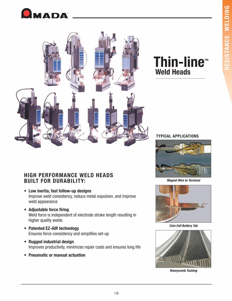
1/8 RESISTANCE WELDING Honeycomb Tacking Coin Cell Battery Tab HIGH PERFORMANCE WELD HEADS BUILT FOR DURABILITY: • Low inertia, fast follow-up designs Improve weld consistency, reduce metal expulsion, and improve weld appearance • Adjustable force firing Weld force is independent of electrode stroke length resulting in higher quality welds • Patented EZ-AIR technology Ensures force consistency and simplifies set-up • Rugged industrial design Improves productivity, minimizes repair costs and ensures long life • Pneumatic or manual actuation Magnet Wire to Terminal TYPICAL APPLICATIONS Thin-line ™ Weld Heads
Transcript of Thinline Weld Heads - amadamiyachiindia.comamadamiyachiindia.com/Amada_Dashboard/uploads/80...80...
1/8
RES
ISTA
NC
E W
ELD
ING
Honeycomb Tacking
Coin Cell Battery Tab
HIGH PERFORMANCE WELD HEADS BUILT FOR DURABILITY:
• Low inertia, fast follow-up designsImprove weld consistency, reduce metal expulsion, and improveweld appearance
• Adjustable force firingWeld force is independent of electrode stroke length resulting inhigher quality welds
• Patented EZ-AIR technologyEnsures force consistency and simplifies set-up
• Rugged industrial designImproves productivity, minimizes repair costs and ensures long life
• Pneumatic or manual actuation
Magnet Wire to Terminal
TYPICAL APPLICATIONS
Thin-line™
Weld Heads
2/8
RES
ISTA
NC
E W
ELD
ING
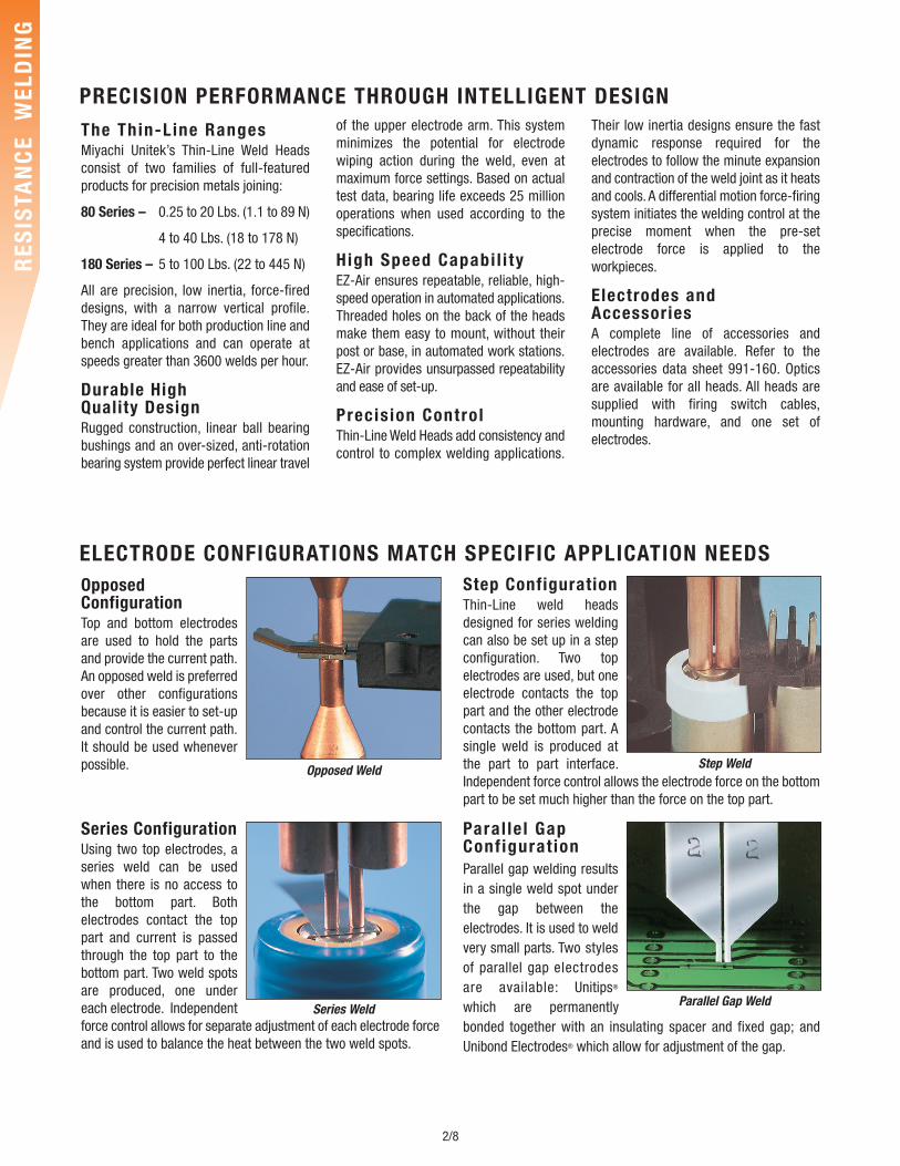
Opposed ConfigurationTop and bottom electrodesare used to hold the partsand provide the current path.An opposed weld is preferredover other configurationsbecause it is easier to set-upand control the current path.It should be used wheneverpossible.
Series ConfigurationUsing two top electrodes, aseries weld can be usedwhen there is no access tothe bottom part. Bothelectrodes contact the toppart and current is passedthrough the top part to thebottom part. Two weld spotsare produced, one undereach electrode. Independentforce control allows for separate adjustment of each electrode forceand is used to balance the heat between the two weld spots.
Step ConfigurationThin-Line weld headsdesigned for series weldingcan also be set up in a stepconfiguration. Two topelectrodes are used, but oneelectrode contacts the toppart and the other electrodecontacts the bottom part. Asingle weld is produced atthe part to part interface.Independent force control allows the electrode force on the bottompart to be set much higher than the force on the top part.
Paral le l GapConf igurat ionParallel gap welding resultsin a single weld spot underthe gap between theelectrodes. It is used to weldvery small parts. Two stylesof parallel gap electrodesare available: Unitips®
which are permanentlybonded together with an insulating spacer and fixed gap; andUnibond Electrodes® which allow for adjustment of the gap.
The Thin-Line RangesMiyachi Unitek’s Thin-Line Weld Headsconsist of two families of full-featuredproducts for precision metals joining:
80 Series – 0.25 to 20 Lbs. (1.1 to 89 N)
4 to 40 Lbs. (18 to 178 N)
180 Series – 5 to 100 Lbs. (22 to 445 N)
All are precision, low inertia, force-fireddesigns, with a narrow vertical profile.They are ideal for both production line andbench applications and can operate atspeeds greater than 3600 welds per hour.
Durable HighQuality DesignRugged construction, linear ball bearingbushings and an over-sized, anti-rotationbearing system provide perfect linear travel
of the upper electrode arm. This systemminimizes the potential for electrodewiping action during the weld, even atmaximum force settings. Based on actualtest data, bearing life exceeds 25 millionoperations when used according to thespecifications.
High Speed Capabi l i tyEZ-Air ensures repeatable, reliable, high-speed operation in automated applications.Threaded holes on the back of the headsmake them easy to mount, without theirpost or base, in automated work stations.EZ-Air provides unsurpassed repeatabilityand ease of set-up.
Precis ion ControlThin-Line Weld Heads add consistency andcontrol to complex welding applications.
Their low inertia designs ensure the fastdynamic response required for theelectrodes to follow the minute expansionand contraction of the weld joint as it heatsand cools. A differential motion force-firingsystem initiates the welding control at theprecise moment when the pre-setelectrode force is applied to theworkpieces.
Electrodes and AccessoriesA complete line of accessories andelectrodes are available. Refer to theaccessories data sheet 991-160. Opticsare available for all heads. All heads aresupplied with firing switch cables,mounting hardware, and one set ofelectrodes.
Opposed Weld
Series WeldParallel Gap Weld
Step Weld
PRECISION PERFORMANCE THROUGH INTELLIGENT DESIGN
ELECTRODE CONFIGURATIONS MATCH SPECIFIC APPLICATION NEEDS
3/8
RES
ISTA
NC
E W
ELD
ING
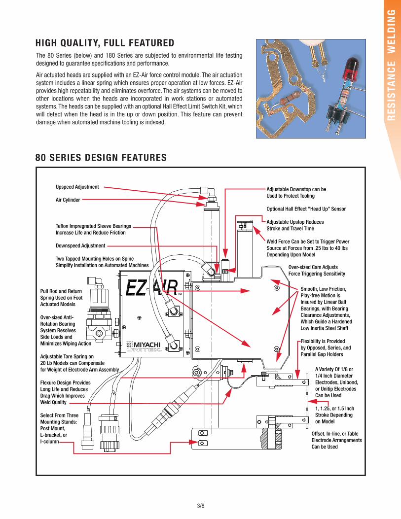
HIGH QUALITY, FULL FEATUREDThe 80 Series (below) and 180 Series are subjected to environmental life testingdesigned to guarantee specifications and performance.
Air actuated heads are supplied with an EZ-Air force control module. The air actuationsystem includes a linear spring which ensures proper operation at low forces. EZ-Airprovides high repeatability and eliminates overforce. The air systems can be moved toother locations when the heads are incorporated in work stations or automatedsystems. The heads can be supplied with an optional Hall Effect Limit Switch Kit, whichwill detect when the head is in the up or down position. This feature can preventdamage when automated machine tooling is indexed.
Upspeed Adjustment
Air Cylinder
Teflon Impregnated Sleeve Bearings Increase Life and Reduce Friction
Downspeed Adjustment
Two Tapped Mounting Holes on Spine Simplify Installation on Automated Machines
Pull Rod and ReturnSpring Used on FootActuated Models
Over-sized Anti-Rotation Bearing System ResolvesSide Loads and Minimizes Wiping Action
Adjustable Tare Spring on20 Lb Models can Compensate for Weight of Electrode Arm Assembly
Flexure Design ProvidesLong Life and ReducesDrag Which ImprovesWeld Quality
Select From Three Mounting Stands: Post Mount,L-bracket, or I-column
Adjustable Downstop can beUsed to Protect Tooling
Optional Hall Effect "Head Up” Sensor
Adjustable Upstop ReducesStroke and Travel Time
Weld Force Can be Set to Trigger Power Source at Forces from .25 lbs to 40 IbsDepending Upon Model
Over-sized Cam AdjustsForce Triggering Sensitivity
Smooth, Low Friction,Play-free Motion isInsured by Linear BallBearings, with BearingClearance Adjustments,Which Guide a HardenedLow Inertia Steel Shaft
Flexibility is Providedby Opposed, Series, andParallel Gap Holders
A Variety Of 1/8 or1/4 Inch DiameterElectrodes, Unibond,or Unitip ElectrodesCan be Used
1, 1.25, or 1.5 Inch Stroke Depending on Model
Offset, In-line, or TableElectrode ArrangementsCan be Used
80 SERIES DESIGN FEATURES
4/8
RES
ISTA
NC
E W
ELD
ING
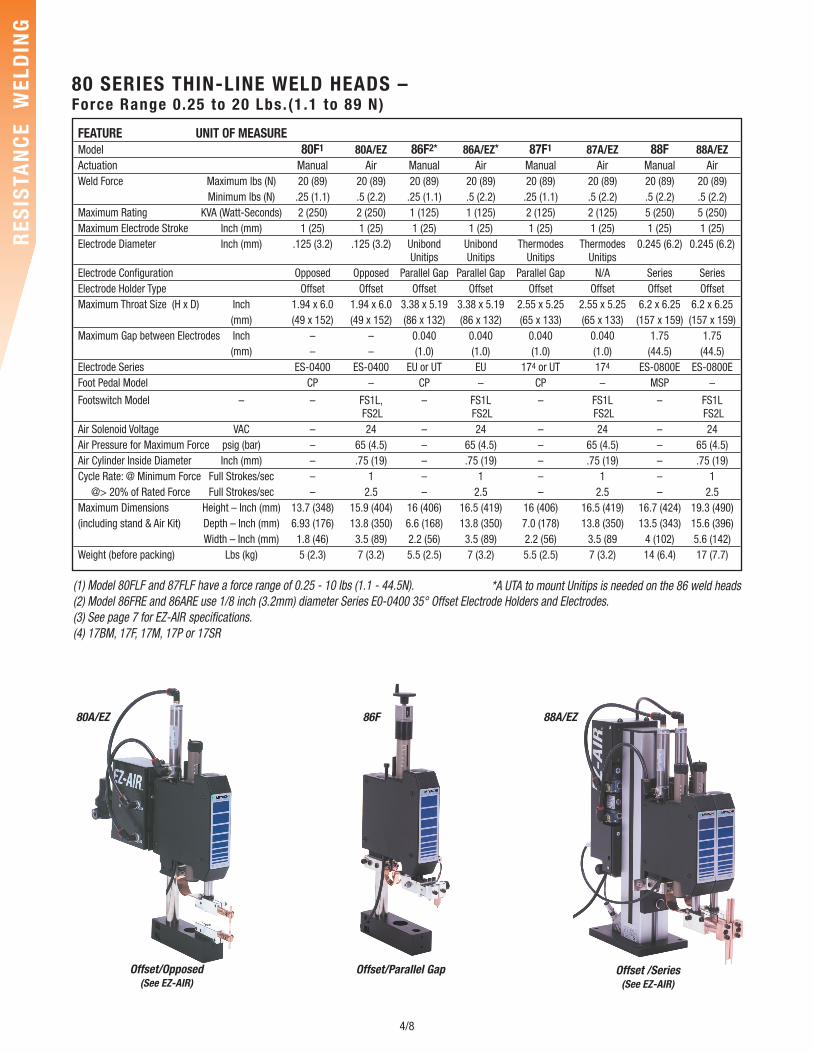
80 SERIES THIN-LINE WELD HEADS – Force Range 0.25 to 20 Lbs. (1 .1 to 89 N)
(1) Model 80FLF and 87FLF have a force range of 0.25 - 10 lbs (1.1 - 44.5N).(2) Model 86FRE and 86ARE use 1/8 inch (3.2mm) diameter Series E0-0400 35° Offset Electrode Holders and Electrodes.(3) See page 7 for EZ-AIR specifications.(4) 17BM, 17F, 17M, 17P or 17SR
80A/EZ
Offset/Opposed(See EZ-AIR)
Offset/Parallel Gap Offset /Series(See EZ-AIR)
86F 88A/EZ
FEATURE UNIT OF MEASUREModel 80F1 80A/EZ 86F2* 86A/EZ* 87F1 87A/EZ 88F 88A/EZActuation Manual Air Manual Air Manual Air Manual AirWeld Force Maximum lbs (N) 20 (89) 20 (89) 20 (89) 20 (89) 20 (89) 20 (89) 20 (89) 20 (89)
Minimum lbs (N) .25 (1.1) .5 (2.2) .25 (1.1) .5 (2.2) .25 (1.1) .5 (2.2) .5 (2.2) .5 (2.2)Maximum Rating KVA (Watt-Seconds) 2 (250) 2 (250) 1 (125) 1 (125) 2 (125) 2 (125) 5 (250) 5 (250)Maximum Electrode Stroke Inch (mm) 1 (25) 1 (25) 1 (25) 1 (25) 1 (25) 1 (25) 1 (25) 1 (25)Electrode Diameter Inch (mm) .125 (3.2) .125 (3.2) Unibond Unibond Thermodes Thermodes 0.245 (6.2) 0.245 (6.2)
Unitips Unitips Unitips UnitipsElectrode Configuration Opposed Opposed Parallel Gap Parallel Gap Parallel Gap N/A Series SeriesElectrode Holder Type Offset Offset Offset Offset Offset Offset Offset OffsetMaximum Throat Size (H x D) Inch 1.94 x 6.0 1.94 x 6.0 3.38 x 5.19 3.38 x 5.19 2.55 x 5.25 2.55 x 5.25 6.2 x 6.25 6.2 x 6.25
(mm) (49 x 152) (49 x 152) (86 x 132) (86 x 132) (65 x 133) (65 x 133) (157 x 159) (157 x 159)Maximum Gap between Electrodes Inch – – 0.040 0.040 0.040 0.040 1.75 1.75
(mm) – – (1.0) (1.0) (1.0) (1.0) (44.5) (44.5)Electrode Series ES-0400 ES-0400 EU or UT EU 174 or UT 174 ES-0800E ES-0800EFoot Pedal Model CP – CP – CP – MSP –
Footswitch Model – – FS1L, – FS1L – FS1L – FS1LFS2L FS2L FS2L FS2L
Air Solenoid Voltage VAC – 24 – 24 – 24 – 24Air Pressure for Maximum Force psig (bar) – 65 (4.5) – 65 (4.5) – 65 (4.5) – 65 (4.5)Air Cylinder Inside Diameter Inch (mm) – .75 (19) – .75 (19) – .75 (19) – .75 (19)Cycle Rate: @ Minimum Force Full Strokes/sec – 1 – 1 – 1 – 1
@> 20% of Rated Force Full Strokes/sec – 2.5 – 2.5 – 2.5 – 2.5Maximum Dimensions Height – Inch (mm) 13.7 (348) 15.9 (404) 16 (406) 16.5 (419) 16 (406) 16.5 (419) 16.7 (424) 19.3 (490)(including stand & Air Kit) Depth – Inch (mm) 6.93 (176) 13.8 (350) 6.6 (168) 13.8 (350) 7.0 (178) 13.8 (350) 13.5 (343) 15.6 (396)
Width – Inch (mm) 1.8 (46) 3.5 (89) 2.2 (56) 3.5 (89) 2.2 (56) 3.5 (89 4 (102) 5.6 (142)Weight (before packing) Lbs (kg) 5 (2.3) 7 (3.2) 5.5 (2.5) 7 (3.2) 5.5 (2.5) 7 (3.2) 14 (6.4) 17 (7.7)
*A UTA to mount Unitips is needed on the 86 weld heads
5/8
RES
ISTA
NC
E W
ELD
ING
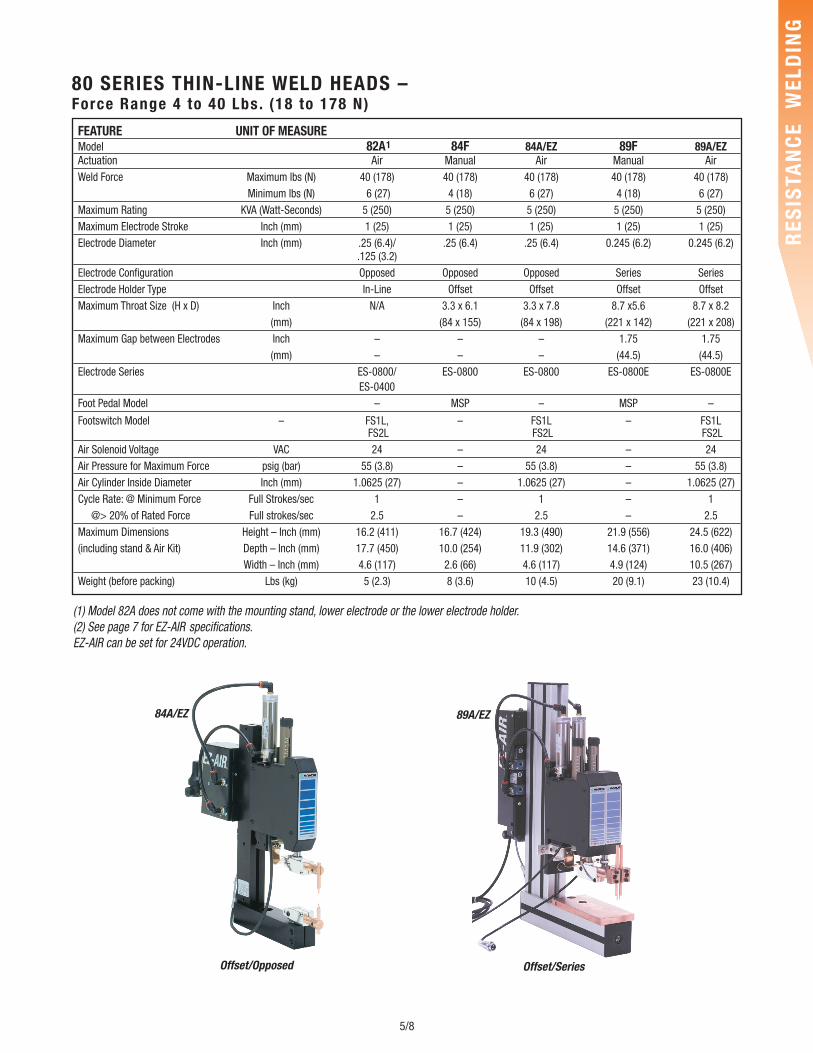
80 SERIES THIN-LINE WELD HEADS – Force Range 4 to 40 Lbs. (18 to 178 N)
(1) Model 82A does not come with the mounting stand, lower electrode or the lower electrode holder. (2) See page 7 for EZ-AIR specifications.EZ-AIR can be set for 24VDC operation.
Offset/Opposed Offset/Series
84A/EZ 89A/EZ
FEATURE UNIT OF MEASUREModel 82A1 84F 84A/EZ 89F 89A/EZActuation Air Manual Air Manual AirWeld Force Maximum lbs (N) 40 (178) 40 (178) 40 (178) 40 (178) 40 (178)
Minimum lbs (N) 6 (27) 4 (18) 6 (27) 4 (18) 6 (27)Maximum Rating KVA (Watt-Seconds) 5 (250) 5 (250) 5 (250) 5 (250) 5 (250)Maximum Electrode Stroke Inch (mm) 1 (25) 1 (25) 1 (25) 1 (25) 1 (25)Electrode Diameter Inch (mm) .25 (6.4)/ .25 (6.4) .25 (6.4) 0.245 (6.2) 0.245 (6.2)
.125 (3.2)Electrode Configuration Opposed Opposed Opposed Series SeriesElectrode Holder Type In-Line Offset Offset Offset OffsetMaximum Throat Size (H x D) Inch N/A 3.3 x 6.1 3.3 x 7.8 8.7 x5.6 8.7 x 8.2
(mm) (84 x 155) (84 x 198) (221 x 142) (221 x 208)Maximum Gap between Electrodes Inch – – – 1.75 1.75
(mm) – – – (44.5) (44.5)Electrode Series ES-0800/ ES-0800 ES-0800 ES-0800E ES-0800E
ES-0400Foot Pedal Model – MSP – MSP –
Footswitch Model – FS1L, – FS1L – FS1LFS2L FS2L FS2L
Air Solenoid Voltage VAC 24 – 24 – 24Air Pressure for Maximum Force psig (bar) 55 (3.8) – 55 (3.8) – 55 (3.8)Air Cylinder Inside Diameter Inch (mm) 1.0625 (27) – 1.0625 (27) – 1.0625 (27)Cycle Rate: @ Minimum Force Full Strokes/sec 1 – 1 – 1
@> 20% of Rated Force Full strokes/sec 2.5 – 2.5 – 2.5Maximum Dimensions Height – Inch (mm) 16.2 (411) 16.7 (424) 19.3 (490) 21.9 (556) 24.5 (622)(including stand & Air Kit) Depth – Inch (mm) 17.7 (450) 10.0 (254) 11.9 (302) 14.6 (371) 16.0 (406)
Width – Inch (mm) 4.6 (117) 2.6 (66) 4.6 (117) 4.9 (124) 10.5 (267)Weight (before packing) Lbs (kg) 5 (2.3) 8 (3.6) 10 (4.5) 20 (9.1) 23 (10.4)
6/8
RES
ISTA
NC
E W
ELD
ING
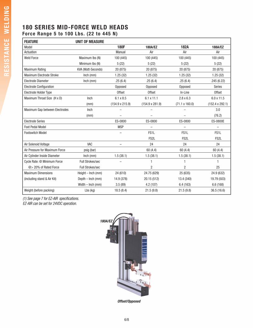
180A/EZ
Offset/Opposed
FEATURE UNIT OF MEASUREModel 180F 180A/EZ 182A 188A/EZActuation Manual Air Air Air
Weld Force Maximum lbs (N) 100 (445) 100 (445) 100 (445) 100 (445)
Minimum lbs (N) 5 (22) 5 (22) 5 (22) 5 (22)
Maximum Rating KVA (Watt-Seconds) 20 (875) 20 (875) 20 (875) 20 (875)
Maximum Electrode Stroke Inch (mm) 1.25 (32) 1.25 (32) 1.25 (32) 1.25 (32)
Electrode Diameter Inch (mm) .25 (6.4) .25 (6.4) .25 (6.4) .245 (6.22)
Electrode Configuration Opposed Opposed Opposed Series
Electrode Holder Type Offset Offset In-Line Offset
Maximum Throat Size (H x D) Inch 6.1 x 8.5 6.1 x 11.1 2.8 x 6.3 6.0 x 11.5
(mm) (154.9 x 215.9) (154.9 x 281.9) (71.1 x 160.0) (152.4 x 292.1)
Maximum Gap between Electrodes Inch – – – 3.0
(mm) – – – (76.2)
Electrode Series ES-0800 ES-0800 ES-0800 ES-0800E
Foot Pedal Model MSP – – –
Footswitch Model – FS1L FS1L FS1L
FS2L FS2L FS2L
Air Solenoid Voltage VAC – 24 24 24
Air Pressure for Maximum Force psig (bar) 60 (4.4) 60 (4.4) 60 (4.4)
Air Cylinder Inside Diameter Inch (mm) 1.5 (38.1) 1.5 (38.1) 1.5 (38.1) 1.5 (38.1)
Cycle Rate: @ Minimum Force Full Strokes/sec – 1 1 1
@> 20% of Rated Force Full Strokes/sec 2 2 25
Maximum Dimensions Height – Inch (mm) 24 (610) 24.75 (629) 25 (635) 24.9 (632)
(including stand & Air Kit) Depth – Inch (mm) 14.9 (378) 20.15 (512) 13.4 (340) 19.79 (503)
Width – Inch (mm) 3.5 (89) 4.2 (107) 6.4 (163) 6.6 (168)
Weight (before packing) Lbs (kg) 18.5 (8.4) 21.5 (9.8) 21.5 (9.8) 36.5 (16.6)
(1) See page 7 for EZ-AIR specifications.EZ-AIR can be set for 24VDC operation.
180 SERIES MID-FORCE WELD HEADSForce Range 5 to 100 Lbs. (22 to 445 N)
7/8
RES
ISTA
NC
E W
ELD
ING
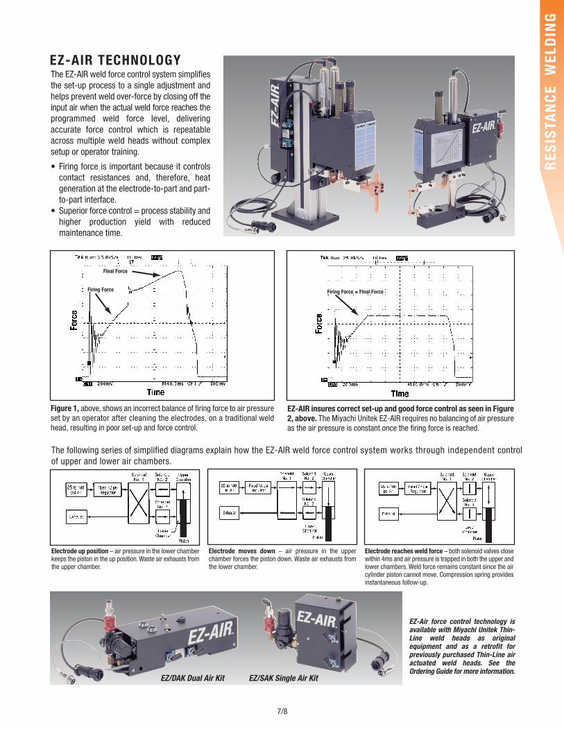
Electrode up position – air pressure in the lower chamberkeeps the piston in the up position. Waste air exhausts fromthe upper chamber.
Electrode moves down – air pressure in the upperchamber forces the piston down. Waste air exhausts fromthe lower chamber.
The following series of simplified diagrams explain how the EZ-AIR weld force control system works through independent controlof upper and lower air chambers.
The EZ-AIR weld force control system simplifiesthe set-up process to a single adjustment andhelps prevent weld over-force by closing off theinput air when the actual weld force reaches theprogrammed weld force level, deliveringaccurate force control which is repeatableacross multiple weld heads without complexsetup or operator training.
• Firing force is important because it controlscontact resistances and, therefore, heatgeneration at the electrode-to-part and part-to-part interface.
• Superior force control = process stability andhigher production yield with reducedmaintenance time.
EZ/DAK Dual Air Kit EZ/SAK Single Air Kit
Figure 1, above, shows an incorrect balance of firing force to air pressureset by an operator after cleaning the electrodes, on a traditional weldhead, resulting in poor set-up and force control.
EZ-AIR insures correct set-up and good force control as seen in Figure2, above. The Miyachi Unitek EZ-AIR requires no balancing of air pressureas the air pressure is constant once the firing force is reached.
Firing Force
Final Force
Firing Force = Final Force
EZ-Air force control technology isavailable with Miyachi Unitek Thin-Line weld heads as originalequipment and as a retrofit forpreviously purchased Thin-Line airactuated weld heads. See theOrdering Guide for more information.
Electrode reaches weld force – both solenoid valves closewithin 4ms and air pressure is trapped in both the upper andlower chambers. Weld force remains constant since the aircylinder piston cannot move. Compression spring providesinstantaneous follow-up.
EZ-AIR TECHNOLOGY
09/1
5
8/8
follow us on:
RES
ISTA
NC
E W
ELD
ING
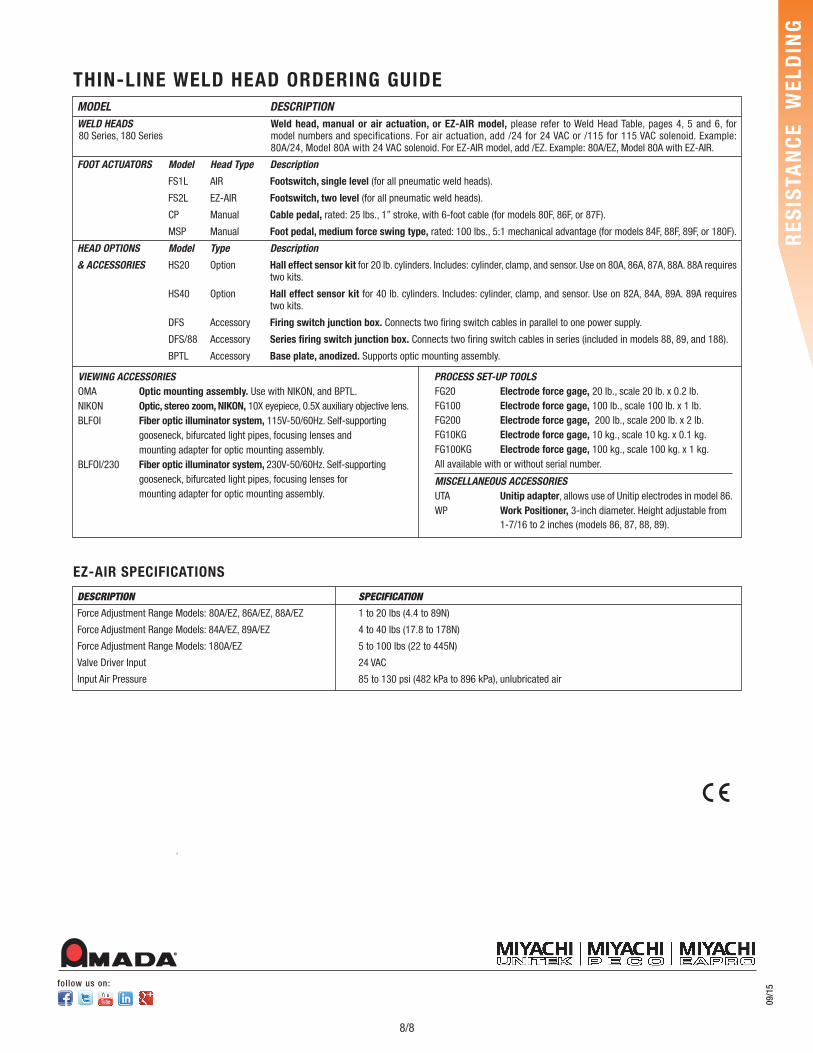
MODEL DESCRIPTIONWELD HEADS Weld head, manual or air actuation, or EZ-AIR model, please refer to Weld Head Table, pages 4, 5 and 6, for
model numbers and specifications. For air actuation, add /24 for 24 VAC or /115 for 115 VAC solenoid. Example:80A/24, Model 80A with 24 VAC solenoid. For EZ-AIR model, add /EZ. Example: 80A/EZ, Model 80A with EZ-AIR.
FOOT ACTUATORS Model Head Type Description
FS1L AIR Footswitch, single level (for all pneumatic weld heads).
FS2L EZ-AIR Footswitch, two level (for all pneumatic weld heads).
CP Manual Cable pedal, rated: 25 lbs., 1” stroke, with 6-foot cable (for models 80F, 86F, or 87F).
MSP Manual Foot pedal, medium force swing type, rated: 100 lbs., 5:1 mechanical advantage (for models 84F, 88F, 89F, or 180F).
HEAD OPTIONS Model Type Description
& ACCESSORIES HS20 Option Hall effect sensor kit for 20 lb. cylinders. Includes: cylinder, clamp, and sensor. Use on 80A, 86A, 87A, 88A. 88A requires two kits.
HS40 Option Hall effect sensor kit for 40 lb. cylinders. Includes: cylinder, clamp, and sensor. Use on 82A, 84A, 89A. 89A requires two kits.
DFS Accessory Firing switch junction box. Connects two firing switch cables in parallel to one power supply.
DFS/88 Accessory Series firing switch junction box. Connects two firing switch cables in series (included in models 88, 89, and 188).
BPTL Accessory Base plate, anodized. Supports optic mounting assembly.
THIN-LINE WELD HEAD ORDERING GUIDE
EZ-AIR SPECIFICATIONS
DESCRIPTION SPECIFICATION
Force Adjustment Range Models: 80A/EZ, 86A/EZ, 88A/EZ 1 to 20 lbs (4.4 to 89N)
Force Adjustment Range Models: 84A/EZ, 89A/EZ 4 to 40 lbs (17.8 to 178N)
Force Adjustment Range Models: 180A/EZ 5 to 100 lbs (22 to 445N)
Valve Driver Input 24 VAC
Input Air Pressure 85 to 130 psi (482 kPa to 896 kPa), unlubricated air
VIEWING ACCESSORIESOMA Optic mounting assembly. Use with NIKON, and BPTL.NIKON Optic, stereo zoom, NIKON, 10X eyepiece, 0.5X auxiliary objective lens.BLFOI Fiber optic illuminator system, 115V-50/60Hz. Self-supporting
gooseneck, bifurcated light pipes, focusing lenses andmounting adapter for optic mounting assembly.
BLFOI/230 Fiber optic illuminator system, 230V-50/60Hz. Self-supportinggooseneck, bifurcated light pipes, focusing lenses formounting adapter for optic mounting assembly.
80 Series, 180 Series
PROCESS SET-UP TOOLSFG20 Electrode force gage, 20 lb., scale 20 lb. x 0.2 lb.FG100 Electrode force gage, 100 lb., scale 100 lb. x 1 lb.FG200 Electrode force gage, 200 lb., scale 200 lb. x 2 lb.FG10KG Electrode force gage, 10 kg., scale 10 kg. x 0.1 kg.FG100KG Electrode force gage, 100 kg., scale 100 kg. x 1 kg.All available with or without serial number.
MISCELLANEOUS ACCESSORIESUTA Unitip adapter, allows use of Unitip electrodes in model 86.WP Work Positioner, 3-inch diameter. Height adjustable from
1-7/16 to 2 inches (models 86, 87, 88, 89).
MADa