ThimbleSense: a fingertip-wearable tactile sensor for grasp analysis
12
1939-1412 (c) 2015 IEEE. Translations and content mining are permitted for academic research only. Personal use is also permitted, but republication/redistribution requires IEEE permission. See http://www.ieee.org/publications_standards/publications/rights/index.html for more information. This article has been accepted for publication in a future issue of this journal, but has not been fully edited. Content may change prior to final publication. Citation information: DOI 10.1109/TOH.2015.2482478, IEEE Transactions on Haptics 1 ThimbleSense: a fingertip-wearable tactile sensor for grasp analysis Edoardo Battaglia, Matteo Bianchi, Alessandro Altobelli, Giorgio Grioli, Manuel G. Catalano, Alessandro Serio, Marco Santello and Antonio Bicchi Abstract—Accurate measurement of contact forces between hand and grasped objects is crucial to study sensorimotor control during grasp and manipulation. In this work we introduce ThimbleSense, a prototype of individual-digit wearable force/torque sensor based on the principle of intrinsic tactile sensing. By exploiting the integration of this approach with an active marker-based motion capture system, the proposed device simultaneously measures absolute position and orientation of the fingertip, which in turn yields measurements of contacts and force components expressed in a global reference frame. The main advantage of this approach with respect to more conventional solutions is its versatility. Specifically, ThimbleSense can be used to study grasping and manipulation of a wide variety of objects, while still retaining complete force/torque measurements. Nevertheless, validation of the proposed device is a necessary step before it can be used for experimental purposes. In this work we present the results of a series of experiments designed to validate the accuracy of ThimbleSense measurements and evaluate the effects of distortion of tactile afferent inputs caused by the device’s rigid shells on grasp forces. ✦ 1 I NTRODUCTION G RASPING objects is a mundane, and yet complex, ac- tivity and one of the primary actions to explore and interact with the external world. For these reasons it is not surprising that many studies have been devoted to understanding neuroscientific aspects underpinning human control of forces during object grasp. For example in [1] Flanagan et al. highlight the importance of contact events in the control of manipulation tasks and the importance of predictive control mechanisms that are based on knowl- edge of object properties. Moreover, in [2] Johansson and Flanagan address how the brain uses tactile information in manipulation tasks, discussing in particular the notion that planning and control is centered on mechanical events that mark transitions between consecutive action phases, and that represent sub-goals of the overall task. Finally, in [3] Wolpert et al. review the topic of human motor learning, focusing on the computational mechanisms involved. Understanding human grasp is also of interest for its applications to the design of robotic hands and prostheses. In [4] Cutkosky and Howe describe and compare the empir- ical and analytical approach for robotic grasp analysis, with the former focusing on experiments with humans to extract knowledge to help design better artificial hands, and the latter using analytical instruments to model grasp from a theoretical point of view. For both approaches, to achieve an exhaustive description a complete characterization in terms of (i) force vector components and (ii) contact locations • E.B., A.S. and A.B. authors are within Centro di Ricerca “E. Piaggio”, University of Pisa, 56126 Pisa, Italy • M.B., A.A., G.G., M.G.C. and A.B. authors are within Italian Institute of Technology, 16163 Genova, Italy. • M.S. is within School of Biological and Health Systems Engineering, Arizona State University, 85280 Tempe (AZ), USA Fig. 1: Concept of the ThimbleSense digit-wearable tactile sensor. is necessary (see [5] for what concerns the importance of such information in humans and [6] for its relevance for what concerns the mathematical modeling of grasping). Additionally, in ideal conditions the sensing process should be able to minimally constrain the pose of the human hand at contact (iii), to capture the human control aspects with no interference. Finally, preservation of the cutaneous feedback on the fingertips (iv) is also important, since it has been shown that it plays a vital role in grasp force control ([7], [8], [9]). Unfortunately, satisfying all these requirements simultaneously is extremely challenging, and thus technical solutions generally have to resort to a compromise. A common approach to the problem of measuring forces from the human hand is to build gloves with pressure sensors, which however only provide information about normal forces, and thus do not offer a complete force measurement (i) and can not in general offer a solution for contact point estimation (ii) (see examples reviewed by Dipietro et al. in [10]). More advanced wearable solutions exist such as the one exploiting analysis of the fingernail coloration described by Grieve et al. in [11], which conserves cutaneous cues (iv) but still does not provide torque mea-
Transcript of ThimbleSense: a fingertip-wearable tactile sensor for grasp analysis

1939-1412 (c) 2015 IEEE. Translations and content mining are permitted for academic research only. Personal use is also permitted, but republication/redistribution requires IEEEpermission. See http://www.ieee.org/publications_standards/publications/rights/index.html for more information.
This article has been accepted for publication in a future issue of this journal, but has not been fully edited. Content may change prior to final publication. Citation information: DOI10.1109/TOH.2015.2482478, IEEE Transactions on Haptics
1
ThimbleSense: a fingertip-wearabletactile sensor for grasp analysis
Edoardo Battaglia, Matteo Bianchi, Alessandro Altobelli, Giorgio Grioli,Manuel G. Catalano, Alessandro Serio, Marco Santello and Antonio Bicchi
Abstract—Accurate measurement of contact forces between hand and grasped objects is crucial to study sensorimotor control duringgrasp and manipulation. In this work we introduce ThimbleSense, a prototype of individual-digit wearable force/torque sensor based onthe principle of intrinsic tactile sensing. By exploiting the integration of this approach with an active marker-based motion capture system,the proposed device simultaneously measures absolute position and orientation of the fingertip, which in turn yields measurements ofcontacts and force components expressed in a global reference frame. The main advantage of this approach with respect to moreconventional solutions is its versatility. Specifically, ThimbleSense can be used to study grasping and manipulation of a wide variety ofobjects, while still retaining complete force/torque measurements. Nevertheless, validation of the proposed device is a necessary stepbefore it can be used for experimental purposes. In this work we present the results of a series of experiments designed to validate theaccuracy of ThimbleSense measurements and evaluate the effects of distortion of tactile afferent inputs caused by the device’s rigidshells on grasp forces.
�
1 INTRODUCTION
GRASPING objects is a mundane, and yet complex, ac-tivity and one of the primary actions to explore and
interact with the external world. For these reasons it isnot surprising that many studies have been devoted tounderstanding neuroscientific aspects underpinning humancontrol of forces during object grasp. For example in [1]Flanagan et al. highlight the importance of contact eventsin the control of manipulation tasks and the importanceof predictive control mechanisms that are based on knowl-edge of object properties. Moreover, in [2] Johansson andFlanagan address how the brain uses tactile information inmanipulation tasks, discussing in particular the notion thatplanning and control is centered on mechanical events thatmark transitions between consecutive action phases, andthat represent sub-goals of the overall task. Finally, in [3]Wolpert et al. review the topic of human motor learning,focusing on the computational mechanisms involved.
Understanding human grasp is also of interest for itsapplications to the design of robotic hands and prostheses.In [4] Cutkosky and Howe describe and compare the empir-ical and analytical approach for robotic grasp analysis, withthe former focusing on experiments with humans to extractknowledge to help design better artificial hands, and thelatter using analytical instruments to model grasp from atheoretical point of view. For both approaches, to achieve anexhaustive description a complete characterization in termsof (i) force vector components and (ii) contact locations
• E.B., A.S. and A.B. authors are within Centro di Ricerca “E. Piaggio”,University of Pisa, 56126 Pisa, Italy
• M.B., A.A., G.G., M.G.C. and A.B. authors are within Italian Instituteof Technology, 16163 Genova, Italy.
• M.S. is within School of Biological and Health Systems Engineering,Arizona State University, 85280 Tempe (AZ), USA
Fig. 1: Concept of the ThimbleSense digit-wearable tactilesensor.
is necessary (see [5] for what concerns the importance ofsuch information in humans and [6] for its relevance forwhat concerns the mathematical modeling of grasping).Additionally, in ideal conditions the sensing process shouldbe able to minimally constrain the pose of the human handat contact (iii), to capture the human control aspects with nointerference. Finally, preservation of the cutaneous feedbackon the fingertips (iv) is also important, since it has beenshown that it plays a vital role in grasp force control ([7],[8], [9]). Unfortunately, satisfying all these requirementssimultaneously is extremely challenging, and thus technicalsolutions generally have to resort to a compromise.
A common approach to the problem of measuring forcesfrom the human hand is to build gloves with pressuresensors, which however only provide information aboutnormal forces, and thus do not offer a complete forcemeasurement (i) and can not in general offer a solutionfor contact point estimation (ii) (see examples reviewed byDipietro et al. in [10]). More advanced wearable solutionsexist such as the one exploiting analysis of the fingernailcoloration described by Grieve et al. in [11], which conservescutaneous cues (iv) but still does not provide torque mea-

1939-1412 (c) 2015 IEEE. Translations and content mining are permitted for academic research only. Personal use is also permitted, but republication/redistribution requires IEEEpermission. See http://www.ieee.org/publications_standards/publications/rights/index.html for more information.
This article has been accepted for publication in a future issue of this journal, but has not been fully edited. Content may change prior to final publication. Citation information: DOI10.1109/TOH.2015.2482478, IEEE Transactions on Haptics
2
Tekscan Grip System Fingernail sensors Sensorized objects ThimbleSense
a) Normal Forces � � � �
(i) Force measurements b) Shear Forces � � � �
c) Torques � � � �
(ii) Contacts � � � �
(iii) Unconstrained grasp � � � �
(iv) Cutaneous cues � � � �
TABLE 1: Features of some force measurement devices compared with ThimbleSense.
surements nor contact point estimation. Another approachto the problem of force sensing for human hands consistsin building sensorized objects, by assembling parts aroundone or more force/torque (F/T) sensors, and use them tostudy grasping and manipulation with a variable numberof digits. For example, in [12] Santello and Soechting useda sensorized manipulandum to study force coordinationduring five-digits grasping, and in [13] a similar devicewas used to study force coordination during three-digitgrasping in an object rotation task. In [14] Zhang et al. usedan invert T sensorized object to investigate sensorimotormemory representation. A collection of sensorized objectscan be found in [15], where Zatsiorsky and Latash reviewedthe state of art on manipulation analysis.
Force measurement through sensorized objects providesa complete solution for (i). However, it lacks versatility,since it requires building a different object for every taskor task condition. Moreover, most objects built this wayare not satisfactory for what concerns the unconstrainedgrasp requirement (iii), since they impose limitations onthe way grasping can be performed, e.g., placing sensorsat specific locations on the grip devices constraints howsubjects grasp the object ([15]). Even when subjects areallowed to choose contact points on grip devices that donot constrain digit placement at predetermined locations(e.g., Fu et al. [16]), this approach is limited by the difficultyof giving a satisfactory measurement of contacts (ii) whenmore than two digits are used to grasp the object (e.g.Fu et al. [17]). Additionally, neuroscientific studies oftenlimit the orientation of the sensorized object to a givenknown configuration (e.g. parallel to the ground) where itis possible to decompose in a straightforward manner gripvs. load force components and test for the achievement ofequilibrium conditions (e.g. Baud-Bovy and Soechting [18],even if later developments of the system were used in tilt
studies [13], Winges et al. [19]).In this work we present a sensing approach that was
first introduced in a preliminary version in [20], and that forthe first time is able to provide a complete characterizationof (unconstrained) human and robotic grasp in terms offorce measurements and contacts. We propose a fingertipwearable sensor that is able to record all the componentsof forces exerted on the object (i) and at the same time toprovide an estimation of the contact point (ii). As a newcontribution with respect to [20], we introduce the integra-tion of a technique to deal with force measurement biascaused by weight (introduced by Atkeson and Hollerbachin [21] and further developed by Kubus et al. in [22]). This,together with the fact that the sensor is wearable, allowsthe subject to grasp generic objects and to achieve reliablemeasurements in any grasp orientation, thus solving (iii).Moreover, a major addition to the previous work consistsin a quantitative analysis of the accuracy of measurements.In order to be able to achieve such complete measurementswe deliberately decided to sacrifice cutaneous feedback (iv)on the fingertips: for this reason in this work an evaluationof the ThimbleSense in experiments with humans was alsoperformed, to evaluate the effects on grip force during a taskand define the field of application of the device accordingly.
To better define where ThimbleSense is placed in thescenery of hand force sensing, we report in Table 1 asummary of the devices mentioned in the introduction andof their features, together with the features of ThimbleSenseitself.
2 CONCEPT
Measurement of forces and torques on a fingertip can becast as a generic structural mechanics problem. To try andanalyze the possible solutions, let us abstract from the phys-ical problem, and consider the simple 2D example shown in
(a) No sensor. (b) External. (c) Integrated. (d) Basal. (e) Remote. (f) ThimbleSense concept.
Fig. 2: A basic loaded structure (a), possible ways to sense the load (b-e), and the concept behind our shell-based wearabledesign (f).

1939-1412 (c) 2015 IEEE. Translations and content mining are permitted for academic research only. Personal use is also permitted, but republication/redistribution requires IEEEpermission. See http://www.ieee.org/publications_standards/publications/rights/index.html for more information.
This article has been accepted for publication in a future issue of this journal, but has not been fully edited. Content may change prior to final publication. Citation information: DOI10.1109/TOH.2015.2482478, IEEE Transactions on Haptics
3
Fig. 2a. A rigid body A, attached to a frame, withstands aforce P applied on a point O at position l, perpendicularlywith respect to its main axis. Let us suppose that a sensorS, able to measure force F and torque M applied on itssurface, is available.
The simplest course of action to measure the appliedforce is interposing the sensor between the applied forceand the object A, as shown in fig. 2b. This solution, whichis in general possible only when the position l is known a-priori, has the disavantage of dislocating the point in whichthe force P is applied from the original O to the remoteO′. This displacement could be recovered by excavating ahole inside the object A and using it to integrate the sensor(fig. 2c); or it could be removed altogether by splitting thestructure in two parts, separating body A from the frameand interposing the sensor between them, as in fig. 2d.This would allow, from the measurements of force F andtorque M , the straightforward reconstruction of P = Fand l = M
P , and thus of both the magnitude and positionof the contact force. It is worth pointing out that withouttorque measurement it would not be possible to estimatethe position of the contact.
The three approaches exposed so far lead to the designof common sensorized objects, but they can not be appliedto a human finger: approaches 2c and 2d are invasive withrespect to the finger, whereas approach 2b is invasive withrespect to the grasp itself, owing to the typical dimensionsof force/torque sensors. The problem can then be definedas designing a sensor capable of results similar to thoseobtainable with approach 2d (simultaneous reconstructionof force and contact position), which can be placed on thefinger without completely altering the grasp with interpo-sition of a cumbersome object between the finger and thecontact. Fig. 2f shows a possible solution: by assembling thesensor S between the object A and a properly designed shellB we obtain a system which is completely non-invasive tothe finger, while also minimizing alteration to the way theload is applied. In this regard it can be noticed that, as insolution 2b, the load is not directly applied on point Obut on a different point O′; however, unlike solution 2b,a proper design of the shell B can substantially reduce thedistance OO′. This last solution was selected for our device.
Following this concept, a F/T sensor is assembled be-tween an inner and an outer shell separated by a gap. Thefinger is placed inside the inner shell, and once the outershell gets in contact with an object the applied mechanicalaction is routed though the sensor, which constitutes theonly mechanical coupling element between the two shells.This design allows a complete measurement of forces andtorques. Specifically, as the geometry of the external supportis known, it is possible to obtain the position of the contactcentroid of the loading force P , through the intrinsic tactilesensing algorithm defined by Bicchi et al. in [23]. More ingeneral, given a surface S with an outward normal definedeverywhere, and a distribution Δ of compressive tractionsapplied on it, the contact centroid is defined as a point csuch that a wrench exists which is equivalent to Δ andconsists of a force p directed into S applied to c and a puretorque q about the contact normal n. All this quantities canbe obtained from the intrinsic tactile algorithm; we refer theinterested reader to [23] for more details.
A number of factors must be taken into account to obtaina functional design, namely:
• Size: the device must be as small as possible, to mini-mize encumbrance. Consequently, all layers betweenfinger and external surface of the outer shell must beas thin as possible. At the same time, the layers needto be thick enough to guarantee a stiffness sufficientto keep the outer shell separated from the inner shellwhen a load is applied.
• Weight: the device needs to be light, to minimize theeffort necessary to carry it. Therefore a material witha high stiffness/weight ratio should be chosen.
• Ergonomics: the device must be shaped in such a wayas to leave finger movements unhindered as much aspossible.
Overall, the grasping process should ideally be unaffectedby wearing the thimbles. If so, it should be possible to seam-lessly wear five devices, one on each fingertip, without themexcessively interfering with hand movements and graspingcapabilities. However, the fact that a rigid shell is placedover the fingertip will necessarily alter grasp control. Thisissue was studied by Lederman and Klatzky in [24], whereit was shown that wearing a rigid shell on the fingertipssignificantly alters haptic recognition of common objects. Asubstantial part of the validation procedure presented in thispaper will address this issue.
3 DESIGN AND IMPLEMENTATION
To finalize the mechanical design of the ThimbleSense shells,the ATI nano 17 six axis F/T sensor was selected: thesensors used in all experiments performed for this paperhad SI-50-0.5 calibration (see the ATI website [25] for moredetails and sensor characteristics). Because of its high stiff-ness/weight ratio, the material chosen to build the thimblesis aluminium. To minimize weight and encumberance of thedevice, a Finite Element Analysis (FEA) was performed onthe CAD model of the device to determine the minimumthickness for the shells and the gap, while still ensuringseparation between the shells when they elastically deformunder load application. To perform FEA, a load model isneeded. From some basic tests performed by pressing afinger on a high precision scale, reasonable bounds of theforces applied were estimated. An average value for theforce was 10 N, whereas 35 N was the higher limit. Tobe conservative, loads on the structure were modeled aslocalized forces applied on the bottom of the open ends ofeither the inner or the outer shell.
A custom material was defined to describe the sensormechanical properties, with elastic modulus coherent withelastic constants from the data sheet. Trials were performedfor various levels of thickness. Here we present the resultsfor a design with 1 mm thickness for both shells and the gap.Figure 3 shows a static structural model with a localizedforce applied on the inner shell. It can be seen that the sim-ulation results show deformations smaller than 1 mm. Sincethe load model chosen is an overestimation of the actualload, this was deemed to be adequate from a mechanicalpoint of view. Figure 4 shows a load model where a force isapplied on the outer shell. In this case the force also exhibits
1939-1412 (c) 2015 IEEE. Translations and content mining are permitted for academic research only. Personal use is also permitted, but republication/redistribution requires IEEEpermission. See http://www.ieee.org/publications_standards/publications/rights/index.html for more information.
This article has been accepted for publication in a future issue of this journal, but has not been fully edited. Content may change prior to final publication. Citation information: DOI10.1109/TOH.2015.2482478, IEEE Transactions on Haptics
4
a significant lateral component. The deformation is close to1 mm, which is considered to be acceptable owing to thehigh load.
It is worth noting that it would not be desirable tohave a thicker shell, since that would cause greater weightand encumbrance. Conversely, reducing the shells’ thicknesscould cause them to come in contact when a load is applied.The result of our design procedure is shown in Figure 5a,which illustrates an exploded view of the final CAD model,together with the list of components of one ThimbleSense.The final mass of the device is 22 grams, which includes9 grams from the F/T sensor. Figure 5b shows boundarydimensions of the device.
Grasping objects with a smooth, metal thimble is not aneasy task due to the very low friction. To facilitate the task,an artificial fingerpad made of latex and rubber was appliedto the outer shell, to mimic the natural frictional propertiesof human fingerpads (Figure 6a). This cover also allowsfor some deformation during contact, which increases thecontact area: while this is no replacement for the complianceof a fingertip, we found that it made grasping objects easierrespect to the making paint solution that was used in [20].
The last element of the thimble design is a reliable wayto place it on the fingertips. Ideally, we would like theinner surface of the thimble to be perfectly attached to theskin. To minimize the relative movement between the deviceand the hand, we used tight finger gloves with extremitiescovered in velcro loops (Figure 6b), while velcro hooks areapplied inside the inner shell portion of the ThimbleSense.This component ensures that the thimbles stay attached tothe fingertips and makes the device wearable. Thanks to itscompliance, velcro also acts as a soft padding, and helpsadapting the thimble to a broader range of finger sizes. Ofcourse this cannot account for all possible size variations: inorder to achieve that different sizes need to be provided forthe thimbles, which will be done in future work.
4 MOTION CAPTURE INTEGRATION
So far we have described a system that allows us to measuregeneralized forces applied to a thimble, which is worn onfingertips while grasping objects. However, the measure-ments of the F/T sensor are expressed in a frame that isattached to the thimble itself. To locate them in a globalreference frame we need to obtain position and orientationof the thimbles. Position and orientation of a rigid bodycan be estimated from the position of a number of points
(a) Model of load. (b) Results.
Fig. 3: FEM analysis: load on the inner shell.
(a) Model of load. (b) Results.
Fig. 4: FEM analysis: load with lateral component on theouter shell.
(a) Exploded view. (b) Dimensions.
Fig. 5: Shell based wearable device: final design.
attached to it, for example by using the algorithm describedby Eggert et al. in [26]. It is worth noting that this algorithmrequires at least three non-aligned points to be effective.
Coordinates of points attached to the thimble can beobtained, for example, by using a motion capture systemand placing LED markers on a support attached to thethimble. In our setup, we chose the Phase Space motion
(a) Artificial finger pad. (b) Finger gloves.
Fig. 6: Setup used to keep thimbles on fingertips.
(a) CAD model. (b) Physical realization.
:
Fig. 7: ABS support for Phase Space markers.

1939-1412 (c) 2015 IEEE. Translations and content mining are permitted for academic research only. Personal use is also permitted, but republication/redistribution requires IEEEpermission. See http://www.ieee.org/publications_standards/publications/rights/index.html for more information.
This article has been accepted for publication in a future issue of this journal, but has not been fully edited. Content may change prior to final publication. Citation information: DOI10.1109/TOH.2015.2482478, IEEE Transactions on Haptics
5
capture system [27], and designed and realized suitable ABSplastic supports to attach the LED beacons to the thimbles,which are all uniquely identified by the system throughan ID. To make sure that the minimum number of threemarkers needed to estimate rigid body motion is alwaysavailable, four marker slots were designed on the support,to be more robust to occasional loss of markers during theacquisition. Such slots are all placed at different heightsover the surface of the support, to maximize visibility. TheCAD model and physical realization are shown in Figure 7.Knowledge of the thimbles orientation allows us to expressforces and measurements in a fixed base reference frame{B}. From now on all quantities will be expressed in {B},unless specified.
It is worth pointing out that, while the choice of amotion capture system represented a convenient solutionto our problem of estimating position and orientation ofThimbleSense, it is not an intrinsic part of the device. Anysolution that can be employed to measure position andorientation of the fingertips could be adapted to replaceit: consideration of different methods will be part of futurework.
5 WEIGHT BIAS COMPENSATION
To avoid measurement errors the F/T sensors need to bezeroed before each acquisition. This static zeroing cannothowever take into account the bias that a body attachedto the sensor induces with its weight when orientationchanges. In this case it is possible to compensate for theweight-induced bias from knowledge of the mass and ofthe center of mass coordinates of the structure attached. Inparticular we used the techniques described in [21], [22],applying it on data acquired during a motion for whichthe ThimbleSense orientation was slowly changed aroundthe whole workspace, with no object being grasped. Underthese conditions the dynamic actions can be neglected andthe F/T measurements collected can be ascribed only to theweight of the external shell and the ABS support.
(a) Thumb force.
0 20 40 600
0.05
0.1
0.15
0.2
0.25
0.3
Time (s)
Forc
e M
odul
e (N
)
weight compensationno compensation
(b) Thumb torque.
0 20 40 600
1
2
3
4
5
6
Time (s)
Torq
ue M
odul
e (N
mm
) weight compensationno compensation
Fig. 8: Measurement errors during calibration with andwithout bias removal.
Figure 8 shows measurements of the norm of force andtorque for the thumb, with and without compensation. Itcan be seen that the error with respect to the expected zerovalue is consistently lower when weight compensation isapplied. Similar results are observed for the other fingers,as quantified by the Root Mean Square Errors in Table 2.Notice that the error is reduced to approximately one thirdof the error without compensation.
Force (N) Torque (N mm)Thumb 0.03 0.12 0.61 2.16Index 0.03 0.09 0.53 1.84
Middle 0.03 0.11 0.69 2.15Ring 0.03 0.11 0.68 1.95Little 0.04 0.11 0.82 1.80
TABLE 2: RMSE for each finger during calibration: with(left) and without (right) weight compensation
(a) Experiment setup. (b) Reconstruction and basereference frame {B}.
Fig. 9: Ball grasp and reconstruction.
6 VALIDATION OF MEASUREMENTS
In [20] a first validation of measurements from the devicewas performed, which however was mostly done in simplesingle-finger configurations. Complete force and contactreconstruction was obtained in a few sample experiments,but no quantitative validation was performed in these ex-periments. In this section we propose a validation of thedevice for full multifingered grasping, that uses classic robotgrasping analysis in the framework presented by Bicchi in[6]. A subject (male, age 27) was asked to grasp two balls ofdifferent weights while wearing ThimbleSense on fingertips.The first object was a sponge ball (mass m1 = 0.053 Kg,radius R1 = 50 mm) which was grasped with the wholehand (number of fingers used nf = 5), while the secondwas a tennis ball filled tightly with iron (mass m2 = 0.32Kg, radius R2 = 33 mm), which was grasped with fourfingers (nf = 4) owing to its smaller radius. In both casesthe subject was instructed to lift the ball, squeeze it whileholding it still with forces of different intensities, and putit down again. The validation procedure consisted of twodifferent phases: in the first one the goal was to verifythat the grasp equilibrium condition was fulfilled duringthe holding phase, while in the second we checked that theinternal force variation was inside the null space of the graspmatrix. This way we are able to simultaneously validate allmeasurements of ThimbleSense.
Phase 1 required to verify that the vector of measuredgeneralized forces t ∈ R
6nf , obtained from the fingertipsmeasurements provided by ThimbleSenses, was correctlyrelated to the applied external wrench w ∈ R
6 by the graspequation
w = Gt, (1)

1939-1412 (c) 2015 IEEE. Translations and content mining are permitted for academic research only. Personal use is also permitted, but republication/redistribution requires IEEEpermission. See http://www.ieee.org/publications_standards/publications/rights/index.html for more information.
This article has been accepted for publication in a future issue of this journal, but has not been fully edited. Content may change prior to final publication. Citation information: DOI10.1109/TOH.2015.2482478, IEEE Transactions on Haptics
6
(a) Force error components.
0 10 20 30 40 50−4
−3
−2
−1
0
1
2
Forc
e er
ror (
N)
Time (s)
efxefyefz
(b) Torque error components.
0 10 20 30 40 50−200
−150
−100
−50
0
50
100
150
200
Torq
ue e
rror (
N m
m)
Time (s)
efxefyefz
(c) Cartesian norm of forces on finger tips.
0 10 20 30 40 500
5
10
15
20
25
Time (s)
Forc
es (N
)
Thumb (fT)IndexMiddleRingLittle
Fig. 10: Grasp analysis for the ball of mass m1 = 0.053Kg.
which is valid under quasi-static conditions. The graspmatrix G ∈ R
6×6nf can be written as
G =
(I3 03×3 . . . I3 03×3
∧c1 I3∧cnf
I3
), (2)
where ∧(·) is the skew-matrix operator and c1 . . . cnfare the
contact points coordinates calculated through the intrinsictactile sensing algorithm, expressed in a reference systemwith origin in the center of mass of the ball b and orientedas the fixed base frame {B}.
Since the ball mass m is known, we can assign a nominalvalue for the external wrench w = w = [0, 0,−mg, 0, 0, 0]T ,with g = 9.81 m/s2. The residual error e is thus computedas
e := w −Gt =[efx efy efz eτx eτy eτz
]T, (3)
(a) Force error components.
0 10 20 30 40−4
−3
−2
−1
0
1
2
Forc
e er
ror (
N)
Time (s)
efxefyefz
(b) Torque error components.
0 10 20 30 40−200
−150
−100
−50
0
50
100
150
200
Torq
ue e
rror (
N m
m)
Time (s)
efxefyefz
(c) Cartesian norm of forces on finger tips.
0 10 20 30 400
5
10
15
20
25
Time (s)
Forc
es (N
)
Thumb (fT)IndexMiddleRing
Fig. 11: Grasp analysis for the ball of mass m2 = 0.32Kg.
where [efx efy efz ] and [eτx eτy eτz ] are the force andtorque component error vectors, respectively. Figures 10 and11 show plots of the result for two trials. The followingobservations can be made:
• The overall grasp error tends to increase when fin-gertip forces are higher;
• There is a transition at the beginning and at the endof the task where errors are relatively higher evenif grasp forces are low: this is caused by the factthat the model we are using to calculate error isquasi-static, and as such does not take into accountdynamic actions (equation (1) no longer holds truewhen the ball is moving).
Therefore, it can be interesting to consider a force per-
1939-1412 (c) 2015 IEEE. Translations and content mining are permitted for academic research only. Personal use is also permitted, but republication/redistribution requires IEEEpermission. See http://www.ieee.org/publications_standards/publications/rights/index.html for more information.
This article has been accepted for publication in a future issue of this journal, but has not been fully edited. Content may change prior to final publication. Citation information: DOI10.1109/TOH.2015.2482478, IEEE Transactions on Haptics
7
(a) Ball position b in space.
0 10 20 30 40 50−100
0
100
200
300
400
Coo
rdin
ates
(mm
)
Time (s)
XYZ
(b) Normalized force error.
10 20 30 40−10
−5
0
5
10
15
Perc
enta
ge fo
rce
erro
r
Time (s)
ef%x
ef%y
ef%z
Fig. 12: Error normalization for the ball of mass m1 = 0.053Kg.
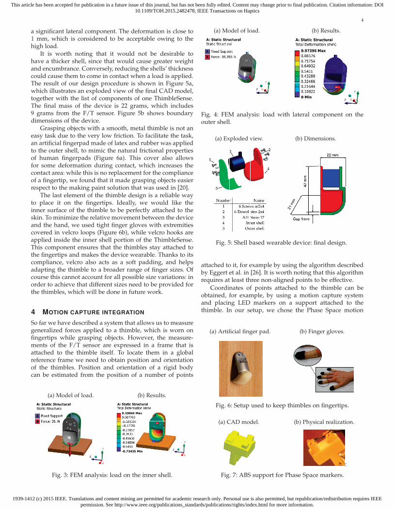
centage error, defined as
ef% :=[ef%
xef%
yef%
z
]= 100
[efxfT
efyfT
efzfT
]T, (4)
where fT is the norm of the force applied by the thumb onthe object, which was chosen as indication of the intensity ofgrasp. The percentage error is considered for the time frameduring which the ball is held still. In order to identify suchtime frame, first we estimated the position of the center ofmass of the ball over time. For each finger, an estimate bi ofthe ball center can be obtained as
bi = ci +Rni, (5)
where R is the radius of the ball in mm and ni is the unitvector normal to the contact surface during grasp, which canbe obtained from the intrinsic tactile algorithm. The globalball center position estimate b can then be obtained as
b =1
nf
nf∑i=1
bi. (6)
This can be used to distinguish the initial and final transientphases from the holding phase. Figures 12a-13a show plotsof b for the two trials considered, each with the time frameof interest highlighted by two vertical dashed lines, whileFigures 12b-13b show plots of the percentage error duringsuch time frame. Tables 3 and 4 report numerical valuesof both absolute and percentage force Root Mean SquareError (RMSE) for both tasks. Torque error is also reported.
(a) Ball position b in space.
0 10 20 30 40−100
0
100
200
300
400
Coo
rdin
ates
(mm
)
Time (s)
XYZ
(b) Normalized force error.
22 24 26 28 30 32 34−10
−5
0
5
10
15
Perc
enta
ge fo
rce
erro
rTime (s)
ef%x
ef%y
ef%z
Fig. 13: Error normalization for the ball of mass m2 = 0.32Kg.
Components fx fy fz
RMSE 0.27 [N] 0.30 [N] 0.34 [N]Percentage RMSE 2.22 % 2.66 % 2.79 %
Components τx [Nmm] τy [Nmm] τz [Nmm]RMSE 19.80 22.11 18.52
TABLE 3: Error for experiments with the ball of mass m1 =0.053 Kg.
It is worth noting that there is no intuitive choice of anormalization quantity for torques; for this reason onlyabsolute torque error is shown.
Phase 2 of the validation exploits the force variationduring the task. Let us consider Δt = tk − t0, where t0is the generalized force measured for an initial sample s0and tk is the force measured in a later sample sk. Sincethe ball is held still, the external wrench w is not changing,and from w = Gt0 = Gtk ∀k follows that Δt lies in the
Components fx fy fz
RMSE 0.17 [N] 0.29 [N] 0.15 [N]Percentage RMSE 1.28 % 2.17 % 1.46 %
Components τx [Nmm] τy [Nmm] τz [Nmm]RMSE 13.68 16.18 8.44
TABLE 4: Error for experiments with the ball of mass m2 =0.32 Kg.

1939-1412 (c) 2015 IEEE. Translations and content mining are permitted for academic research only. Personal use is also permitted, but republication/redistribution requires IEEEpermission. See http://www.ieee.org/publications_standards/publications/rights/index.html for more information.
This article has been accepted for publication in a future issue of this journal, but has not been fully edited. Content may change prior to final publication. Citation information: DOI10.1109/TOH.2015.2482478, IEEE Transactions on Haptics
8
10 20 30 40−0.25
−0.2
−0.15
−0.1
−0.05
0
0.05
0.1
0.15
0.2
Forc
e (N
)
Time (s)
eΠfx
eΠfy
eΠfz
Fig. 14: Internal force projection error components for thetask with nf = 5.
Components Thumb Index Middle Ring Littlem1 = 0.053 Kg
fx [N] 0.077 0.10 0.085 0.082 0.073fy [N] 0.036 0.72 0.17 0.034 0.10fz [N] 0.075 0.068 0.14 0.15 0.32
m2 = 0.32 Kgfx [N] 0.143 0.41 0.34 0.14 n/afy [N] 0.164 0.074 0.20 0.026 n/afz [N] 0.0063 0.054 0.030 0.13 n/a
TABLE 5: RMSE for the force components of eΠ.
nullspace of G (Δt ∈ N (G)). It is known from grasp theoryand linear algebra ([6], Meyer [28]) that (I − G+G), whereI is the identity matrix, is a projector to N (G). Therefore, ifwe compute
ΠG (Δt) := (I −G+G)Δt =[I −GT (GGT )−1G
]Δt (7)
since Δt ∈ N (G) it should be true that ΠG (Δt) = Δt. Wecan then define the error
eΠ := ΠG (Δt)−Δt =
=[eΠfx
eΠfyeΠfz
eΠτxeΠτy
eΠτz
]T. (8)
As an example, figure 14 shows the force components ofsuch error for the trial with the ball of mass m1. A morecomplete representation of results can be found in Table 5,which shows RMSE considering only force components forthe sake of space. RMSE for torques were all of the order of10−3 N mm.
7 TACTILE FEEDBACK IMPAIRMENTEVALUATION
The experiment shown in the previous section focused onvalidating the ThimbleSense measurements. However, thereis another important aspect that needs to be analyzed. Whenhuman users wear the ThimbleSense, a rigid shell is placedon fingertips, which inevitably alters cutaneous perceptionand hence force modulation. In particular we expected sub-jects to exert larger forces to compensate for the distortionin tactile feedback, whose importance in grip control iswell known as we discussed in the Introduction. However,
Fig. 15: Inverted T experiment setup
0 2 4 6 8 10 12 14 16 18 200
2
4
6
8
10
12
Time (s)
Grip
forc
e (N
)
Thumb, inverted TIndex, inverted TThumb, thimbleIndex, thimble
Fig. 16: Grip force data for a representative trial.
as subjects familiarize themselves with the ThimbleSenseand the task, we also expected forces to decrease. In thissection we describe an example of a typical experiment inneuroscientific studies on human grasp control, which isperformed first while wearing ThimbleSense and then withbare fingers. The aim is studying the evolution of graspforces under the two conditions, with the two-fold goal ofevaluating the effect of cutaneous distortion and possibilityof reducing it through practice.
We employed the grip device with the inverted T designused by Zhang et al. in [14]. A total of 4 LED markerswere added on the top to allow estimation of positionand orientation of the sensorized object. The total massof the object was 730 g, with the center of mass of thesystem located in the middle plane. Figure 15 shows theexperimental apparatus. The task consisted in lifting theobject using thumb and index of the right hand. We asked8 subjects (7 males and 1 female, age 28.2 ± 2.8, 5 righthanded and 3 left handed) to perform the experiment, intwo different sessions. All subjects were naive to the use ofThimbleSense, all had no previous history of orthopedic orneurological pathology or trauma to the upper limbs, and allgave their informed consent. The protocols were approvedby the Arizona State University Office of Research Integrityand Assurance. During the first session subjects wore theThimbleSense on the right hand thumb and index fingertips,while for the second session they were asked to perform
1939-1412 (c) 2015 IEEE. Translations and content mining are permitted for academic research only. Personal use is also permitted, but republication/redistribution requires IEEEpermission. See http://www.ieee.org/publications_standards/publications/rights/index.html for more information.
This article has been accepted for publication in a future issue of this journal, but has not been fully edited. Content may change prior to final publication. Citation information: DOI10.1109/TOH.2015.2482478, IEEE Transactions on Haptics
9
the same task with bare fingertips. Both sessions consistedin 30 trials each and at least two days were interposedbetween one session and the other. Subjects could takebreaks whenever they needed, and were given a minimumof a one-minute break after the 15th trial, in order to preventfatigue.
It is known from literature (e.g., [7]) that grip forceduring manipulation is regulated with a relatively lowmargin with respect to the slip condition. Thus, we canuse the difference in the mean steady-state grip force un-der the two conditions as an indication of how much thegrasp is being distorted by the thimbles. Note, however,that large differences between the static friction coefficients(bare fingertips versus latex artificial finger pad againstthe sandpaper covering the graspable surface of the object)might also have contributed to elicit different grip forces.To further investigate this aspect we asked a male right-handed subject (27 year old), with no history of neurologicalor physical impairment, and who did not participate to themain experiment, to perform 5 trials of a standard slip testfor both conditions in order to get an approximate estima-tion of the static friction coefficient, following a proceduresimilar to the one used by Baud-Bovy et al. in [18]. Theaverage value of the static friction coefficient obtained forthe bare fingertip condition (1.20) was similar to the onereported in [18], while the average value obtained with theThimbleSense devices was 1.17. This result led us to neglectthe difference in the friction coefficient between the twoexperimental conditions for subsequent force analyses.
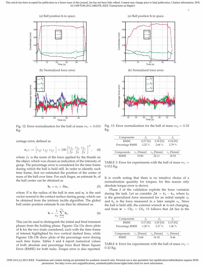
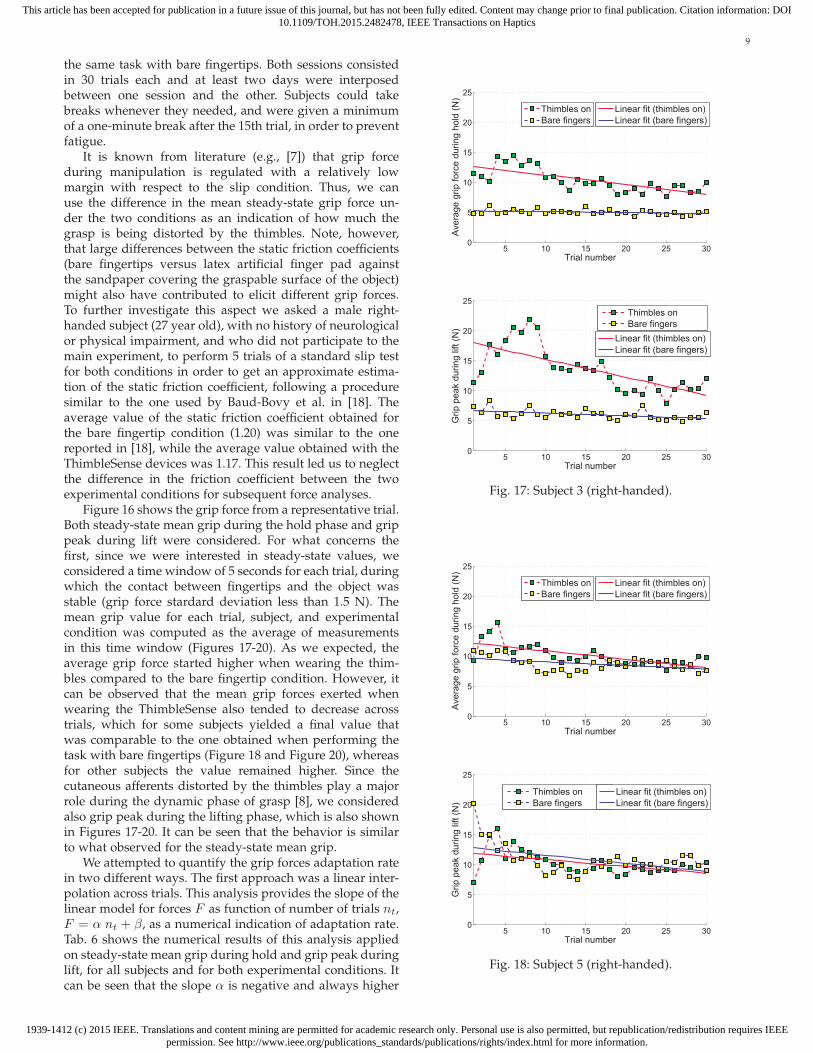
Figure 16 shows the grip force from a representative trial.Both steady-state mean grip during the hold phase and grippeak during lift were considered. For what concerns thefirst, since we were interested in steady-state values, weconsidered a time window of 5 seconds for each trial, duringwhich the contact between fingertips and the object wasstable (grip force stardard deviation less than 1.5 N). Themean grip value for each trial, subject, and experimentalcondition was computed as the average of measurementsin this time window (Figures 17-20). As we expected, theaverage grip force started higher when wearing the thim-bles compared to the bare fingertip condition. However, itcan be observed that the mean grip forces exerted whenwearing the ThimbleSense also tended to decrease acrosstrials, which for some subjects yielded a final value thatwas comparable to the one obtained when performing thetask with bare fingertips (Figure 18 and Figure 20), whereasfor other subjects the value remained higher. Since thecutaneous afferents distorted by the thimbles play a majorrole during the dynamic phase of grasp [8], we consideredalso grip peak during the lifting phase, which is also shownin Figures 17-20. It can be seen that the behavior is similarto what observed for the steady-state mean grip.
We attempted to quantify the grip forces adaptation ratein two different ways. The first approach was a linear inter-polation across trials. This analysis provides the slope of thelinear model for forces F as function of number of trials nt,F = α nt + β, as a numerical indication of adaptation rate.Tab. 6 shows the numerical results of this analysis appliedon steady-state mean grip during hold and grip peak duringlift, for all subjects and for both experimental conditions. Itcan be seen that the slope α is negative and always higher
5 10 15 20 25 300
5
10
15
20
25
Trial number
Aver
age
grip
forc
e du
ring
hold
(N)
Thimbles onBare fingers
Linear fit (thimbles on)Linear fit (bare fingers)
5 10 15 20 25 300
5
10
15
20
25
Trial numberG
rip p
eak
durin
g lif
t (N
)
Thimbles onBare fingers
Linear fit (thimbles on)Linear fit (bare fingers)
Fig. 17: Subject 3 (right-handed).
5 10 15 20 25 300
5
10
15
20
25
Trial number
Aver
age
grip
forc
e du
ring
hold
(N)
Thimbles onBare fingers
Linear fit (thimbles on)Linear fit (bare fingers)
5 10 15 20 25 300
5
10
15
20
25
Trial number
Grip
pea
k du
ring
lift (
N)
Thimbles onBare fingers
Linear fit (thimbles on)Linear fit (bare fingers)
Fig. 18: Subject 5 (right-handed).

1939-1412 (c) 2015 IEEE. Translations and content mining are permitted for academic research only. Personal use is also permitted, but republication/redistribution requires IEEEpermission. See http://www.ieee.org/publications_standards/publications/rights/index.html for more information.
This article has been accepted for publication in a future issue of this journal, but has not been fully edited. Content may change prior to final publication. Citation information: DOI10.1109/TOH.2015.2482478, IEEE Transactions on Haptics
10
5 10 15 20 25 300
5
10
15
20
25
Trial number
Aver
age
grip
forc
e du
ring
hold
(N)
Thimbles onBare fingers
Linear fit (thimbles on)Linear fit (bare fingers)
5 10 15 20 25 300
5
10
15
20
25
Trial number
Grip
pea
k du
ring
lift (
N)
Thimbles onBare fingers
Linear fit (thimbles on)Linear fit (bare fingers)
Fig. 19: Subject 6 (left-handed).
5 10 15 20 25 300
5
10
15
20
25
Trial number
Aver
age
grip
forc
e du
ring
hold
(N)
Thimbles onBare fingers
Linear fit (thimbles on)Linear fit (bare fingers)
5 10 15 20 25 300
5
10
15
20
25
Trial number
Grip
pea
k du
ring
lift (
N)
Thimbles onBare fingers
Linear fit (thimbles on)Linear fit (bare fingers)
Fig. 20: Subject 7 (left-handed).
SubjectAverage grip during hold Grip peak during lift
TH BF TH BF
1 (R)-0.107 -0.0553 -0.141 -0.130 α
1.17e-06 0.0113 3.58e-05 1.82e-04 p value
2 (R)-0.0598 -0.0290 -0.136 -0.129 α
0.0293 0.0761 1.64e-04 1.69e-03 p value
3 (R)-0.131 -0.0160 -0.301 -0.0450 α
4.85e-08 0.191 1.38e-05 7.82e-03 p value
4 (R)-0.131 0.0299 -0.184 -0.0112 α
7.33e-08 0.0218 1.3e-07 0.4153 p value
5 (R)-0.103 -0.0943 -0.111 -0.136 α
2-02e-05 4.84e-05 5.38e-03 7.13e-03 p value
6 (L)-0.160 -0.0145 -0.113 0.0012 α
5.70e-06 0.128 1.31e-03 0.955 p value
7 (L)-0.141 -0.0606 -0.0817 -0.0815 α
0.388 0.612 1.71e-03 8.49e-04 p value
8 (L)-0.286 -0.0757 -0.150 -0.0907 α
0.388 0.612 1.54e-04 8.66e-03 p value
TABLE 6: Mean grip linear fit slope α and p value. (R)indicates right-handed subjects, while (L) indicates left-handed subjects; TH indicates ThimbleSense being placedon the fingers, while BF indicates the bare fingers condition.
1 2 3 4 5 6 7 80
2
4
6
8
10
12
Subject number
Aver
age
grip
on
last
ten
trial
s (N
) Right handed Left handedMean grip force (N)Standard deviation (N)
Fig. 21: Average of the mean grip on the last ten trials foreach subject. There are two bars for each subject: the firstbar represents values while wearing ThimbleSense, whilethe second bar is for bare fingers.
when subjects wear the ThimbleSense, and p-values showthat the value of this slope is always statistically significant,except for some subjects under the bare fingertip conditionwho had grip forces which immediately approached steadystate values. The negative and larger slopes of the linear fitto grip forces across trials indicate that grip forces tended todecrease with practice, and at a higher rate than when usingbare fingertips. It is worth pointing out that the linear fit isnot meant as an actual model of the process, but it is usedas an indication of whether there is learning or not.
The second approach we used to quantify adaptationwas to compare grip force over the latest trials between thetwo experimental conditions. Figure 21 shows the compari-son of the average of the steady-state mean grip during hold

1939-1412 (c) 2015 IEEE. Translations and content mining are permitted for academic research only. Personal use is also permitted, but republication/redistribution requires IEEEpermission. See http://www.ieee.org/publications_standards/publications/rights/index.html for more information.
This article has been accepted for publication in a future issue of this journal, but has not been fully edited. Content may change prior to final publication. Citation information: DOI10.1109/TOH.2015.2482478, IEEE Transactions on Haptics
11
SubjectMean grip force (N)
p-valueTH BF
1 (R) † 7.26±0.69 7.19±0.83 0.920
4 (R) * 5.94±0.43 6.33±0.60 0.0506
5 (R) * 8.9±0.71 8.56±0.81 0.471
6 (L) * 5.33±0.70 6.06±0.57 0.0546
TABLE 7: Steady state mean grip. Paired t-test was used fordata marked with ∗, while Wilcoxon signed rank test wasused for data marked with †. Normality was verified withLilliefors test.
(a) Steady-state mean grip during hold for subject 2.
10 20 30 40 50 600
3
6
9
12
15
18
21
Trial number
Aver
age
grip
forc
e du
ring
hold
(N)
Thimbles on, second block of trialsThimbles on, first blockBare fingers, second blockThimbles on, third block
Linear fit (first block)Linear fit (second block)Linear fit (third block)
(b) Grip peak during lift for subject 2.
10 20 30 40 50 600
3
6
9
12
15
18
21
Trial number
Grip
pea
k du
ring
lift (
N)
Thimbles on, second block of trials
Thimbles on, first blockBare fingers, second blockThimbles on, third block
Linear fit (first block)Linear fit (second block)Linear fit (third block)
Fig. 22: Comparison between the three blocks of trials per-formed on subject 2.
over the last ten trials from the two conditions and each sub-ject (note that subjects 1 to 5 are right-handed, while subjects6 to 8 are left-handed). As it was already observed whencomparing the sample plots of mean grip over number oftrials, results varied across subjects. Specifically, subjectsnumber 1, 4, 5 and 6 exhibited comparable values for themean grip over the last ten trials in the two conditions, forwhich statistical analysis revealed no statistically significantdifference (Table 7). The other half of the subjects, however,
SubjectAverage grip during hold Grip peak during lift
TH (30 trials) TH (60 trials)
2 (R)-0.074 -0.101 α
1.64e-12 1.08e-11 p-value
TABLE 8: Linear fit goodness for the 60-trials block.
still exhibited a significantly higher grip force when wearingthe ThimbleSense.
These results indicate that at least half of the subjectswere able to adapt their steady-state grip forces, despite thedistortion of tactile sensation, to a level comparable to theone found when using bare fingertips. To further investigatethis phenomenon, a third block of trials was presented tosubject 2 who exhibited the largest difference between thefinal values of grip force in the two experimental conditions.For this third block of trials, the subject was asked to repeatthe task while wearing the thimbles, but the number of trialswas increased from 30 to 60 to provide him with more timeto become familiar with ThimbleSense and the task. Thethird block of trials was performed 11 days after the subjectshad performed the second block of trials.
Figure 22 shows the grip force behavior for subject 2 forall three blocks of trials: the average of steady-state meangrip during hold on the last ten trials was 10.65 ± 1.05,5.77 ± 0.44 and 7.53 ± 0.87 N for each block respectively.The final average value of force, while still higher than thefinal value of grip force in the bare fingertip condition, wasconsiderably smaller than the value that was obtained inthe first block. Most importantly, the comparison of datafrom the first and third blocks of trials reveals that the gripforce decreased more rapidly during the third block (thiscan be quantified numerically by comparing values of α inTab. 6 and 8). The initial force β was also smaller. Therefore,these data indicate that the subject who initially exhibitedthe weakest force adaptation benefited from longer practicewith ThimbleSense and the task (α coefficient significantlysmaller than zero), as well as from the previous practice(smaller initial force and more rapid decrease of grip forcerelative to the first block, which was carried in the samecondition as the third).
From these results, we can not claim that a completecompensation of cutaneous feedback distortion can be ob-tained with training. However, this experiment confirmsthat there is some learning, be it device or task related.For this reason we believe that ThimbleSense could beprofitably used in experiments on anticipatory control (e.g.[16]) with distortion of cutaneous feedback. Targeted studiescan be focused on the kinaesthetic aspect of grasp controlwith applications on design and sensing of artificial handsand prostheses, as we further develop in the Conclusions.Finally, it is worth noting that the object never slipped andwas never dropped during the experiments. This, togetherwith the fact that the same object was always used with noshape or size change, minimized the role of visual cues inthe experiment.
8 CONCLUSIONS
In this work, we described the ThimbleSense, a wearabledevice that allows us to obtain measurements of forcesapplied during grasping as well as to estimate the positionof the contact points. Experimental validation evaluated theaccuracy of measurements on grasps of two different balls,leading in both cases to force RMSE less than 0.35 N (lessthan 3% of thumb force norm) and torque RMSE less than 23N mm. We also performed a comparison of grip force evo-lution for a simple thumb-index lifting task, performed with

1939-1412 (c) 2015 IEEE. Translations and content mining are permitted for academic research only. Personal use is also permitted, but republication/redistribution requires IEEEpermission. See http://www.ieee.org/publications_standards/publications/rights/index.html for more information.
This article has been accepted for publication in a future issue of this journal, but has not been fully edited. Content may change prior to final publication. Citation information: DOI10.1109/TOH.2015.2482478, IEEE Transactions on Haptics
12
(a) Fingertip detail. (b) Object grasp.
Fig. 23: Example of application of ThimbleSense on a robot(DLR Hand II).
and without thimbles. This comparison showed a reductionof grip force over the number of trials: indeed, for half of thesubjects the same value of mean steady state grip force wasmeasured for both conditions. Owing to the fact that onlya single simple task was considered, we can not concludefrom this that there was a learning specifically related tothe device: however, we can observe that learning duringthe experiment was not completely hampered by wearingThimbleSense, as instead would happen for subjects whocompletely lost all somatosensory feedback ([7], [9]).
Thanks to its versatility in providing complete measure-ments of forces and contact points during multifingeredgrasps of variously shaped objects, ThimbleSense showspromise to be a powerful tool in the field of wearable hapticsand human hand behavior studies, as long as the limitationsrelated to the cutaneous cues distortion are kept in dueconsideration. Future work will focus on studies on reac-tive grasp and force synergies under impaired cutaneousfeedback, to be used to improve the design of robotic handsand prostheses, e.g. to implement low-level grasp reflexesand for studies on grasp stability. Indeed, the device can beadapted with minor modifications to robotic manipulators(Figure 23 shows a preliminary application on the DLRHand II), to provide a complete set of force and contact pointmeasurements to study grasp stability.
ACKNOWLEDGMENTS
The authors gratefully acknowledge Qiushi Fu, ManoloGarabini, Pranav J. Parikh, Patrick McGurrin, Keivan Mo-jtahedi, and Daisuke Shibata for their valuable advices,and Andrea Di Basco for his unique contribution in thephysical realization of the device. This work was partiallysupported by the European Community funded projectsWEARHAP, PACMAN and SOMA (contracts 601165, 600918and 645599 respectively), by the ERC Advanced Grant no.291166 SoftHands and by the Collaborative Research GrantBCS-1153034 to M. Santello from the National Science Foun-dation (NSF).
REFERENCES
[1] J. R. Flanagan, M. C. Bowman, and R. S. Johansson, “Controlstrategies in object manipulation tasks,” Current Opinion in Neu-robiology, vol. 16, no. 6, pp. 650–659, 2006.
[2] R. S. Johansson and J. R. Flanagan, “Coding and use of tactilesignals from the fingertips in object manipulation tasks,” NatureReviews Neuroscience, vol. 10, no. 5, pp. 345–359, 2009.
[3] D. M. Wolpert, J. Dierichsen, and J. R. Flanagan, “Principles ofsensorimotor learning,” Nature Reviews Neuroscience, vol. 12, pp.739–751, 2011.
[4] M. R. Cutkosky and R. D. Howe, “Human grasp choice and roboticgrasp analysis,” Dextrous robot hands, pp. 5–31, 1990.
[5] R. S. Johansson and I. Birznieks, “First spikes in ensembles ofhuman tactile afferents code complex spatial fingertip events,”Nature neuroscience, vol. 7, no. 2, pp. 170–177, 2004.
[6] A. Bicchi, “On the problem of decomposing grasp and manipu-lation forces in multiple whole limb manipulation,” Int. Journal ofRobotics and Autonomous Systems, vol. 13, no. 2, pp. 127 – 147, 1994.
[7] R. S. Johansson and G. Westling, “Roles of glabrous skin receptorsand sensorimotor memory in automatic control of precision gripwhen lifting rougher or more slippery objects,” Experimental brainresearch, vol. 56, no. 3, pp. 550–564, 1984.
[8] G. Westling and R. S. Johansson, “Responses in glabrous skinmechanoreceptors during precision grip in humans,” ExperimentalBrain Research, vol. 66, no. 1, pp. 128–140, 1987.
[9] D. A. Nowak, S. Glasauer, and J. Hermsdorfer, “How predictiveis grip force control in the complete absence of somatosensoryfeedback?” Brain, vol. 127, no. 1, pp. 182–192, 2004.
[10] L. Dipietro, A. M. Sabatini, and P. Dario, “A survey of glove-basedsystems and their applications,” IEEE Transactions on systems, manand cybernetics, vol. 38, no. 4, pp. 461 – 482, 2008.
[11] T. R. Grieve, J. M. Hollerbach, and S. A. Mascaro, “Force predic-tion by fingernail imaging using active appearance models,” inProceedings of IEEE World Haptics Conference, 2013.
[12] M. Santello and J. F. Soechting, “Force synergies for multifingeredgrasping,” Experimental Brain Research, vol. 133, no. 4, pp. 457 –467, 2000.
[13] S. A. Winges, S. E. Eonta, J. F. Soechting, and M. Flanders, “Multi-digit control of contact forces during rotation of a hand-heldobject,” Journal of neurophysiology, vol. 99, no. 4, pp. 1846–1856,2008.
[14] W. Zhang, A. M. Gordon, Q. Fu, and M. Santello, “Manipulationafter object rotation reveals independent sensorimotor memoryrepresentations of digit positions and forces,” The Journal of Neuro-physiology, vol. 103, no. 6, pp. 2953 – 2964, 2010.
[15] V. M. Zatsiorsky and M. L. Latash, “Multi-finger prehension: Anoverview,” Journal of Motor Behavior, vol. 40, no. 5, pp. 446–476,2008.
[16] Q. Fu, W. Zhang, and M. Santello, “Anticipatory planning andcontrol of grasp positions and forces for dexterous two-digitmanipulation,” The Journal of Neuroscience, vol. 30, no. 27, pp. 9117– 9126, 2010.
[17] Q. Fu, Z. Hasan, and M. Santello, “Transfer of learned manipu-lation following changes in degrees of freedom,” The Journal ofNeuroscience, vol. 31, no. 38, pp. 13 576 – 13 584, 2011.
[18] G. Baud-Bovy and J. F. Soechting, “Two virtual fingers in thecontrol of the tripod grasp,” Journal of Neurophysiology, vol. 86,no. 2, pp. 604–615, 2001.
[19] S. A. Winges, S. E. Eonta, J. F. Soechting, and M. Flanders,“Effects of object compliance on three-digit grasping,” Journal ofNeruphysiology, vol. 101, no. 5, pp. 2447–2458, 2009.
[20] E. Battaglia, G. Grioli, M. G. Catalano, M. Santello, and A. Bicchi,“Thimblesense: an individual-digit wearable tactile sensor forexperimental grasp studies,” in Proceedings of IEEE InternationalConference on Robotics and Automation, 2014.
[21] C. G. Atkeson, C. H. An, and J. M. Hollerbach, “Rigid body loadidentification for manipulators,” in Proceedings of IEEE Conferenceon Decision and Control, 1985.
[22] D. Kubus, T. Kroger, and F. M. Wahl, “On-line rigid objectrecognition and pose estimation based on inertial parameters,”in Proceedings of Intelligent Robots and Systems, 2007.
[23] A. Bicchi, J. K. Salisbury, and D. L. Brock, “Contact sensing fromforce measurement,” The International Journal of Robotics Research,vol. 12, pp. 249–262, 1993.
[24] S. J. Lederman and R. L. Klatzky, “Haptic identification of commonobjects: Effects of constraining the manual exploration process,”Perception & Psychophysics, vol. 66, no. 4, pp. 618 – 628, 2004.
[25] ATI. F/t sensor: Nano17. [Online]. Available: http://www.ati-ia.com/products/ft/ft models.aspx?id=Nano17
[26] D. W. Eggert, A. Lorusso, and R. B. Fisher, “Estimating 3-d rigidbody transformations: a comparison of four major algorithms,”Machine Vision and Applications, vol. 9, pp. 272 – 290, 1997.
[27] P. Space. Motion capture system. [Online]. Available: http://www.phasespace.com/
[28] C. D. Meyer, Matrix Analysis and Applied Linear Algebra. Philadel-phia, PA: Society for Industrial and Applied Mathematics, 2000.