THIELSCH ENGINEERING, INC.
8
THIELSCH ENGINEERING, INC. THE VALUE OF PMI TESTING JUST BECAUSE IT’S SPECIFIED DOESN’T MEAN IT’S TESTIFIED In the rigid world of engineering many times we become complacent with specifications and designs. We trust that what is documented on our construction blueprints is what we actually have installed in our facility. However, this belief could not be further than the truth, and, in fact, could be considered a risky assumption. As a failure analysis company with over 30 years of history conducting inspections and evaluations of high‐temperature and high‐pressure components, we have seen our share of material discrepancies. In fact, the number of cases where Thielsch Engineering have identified either improper weld filler material, or improper spool piece material would likely be alarming to the average power plant personnel. Fortunately, in many of these cases, the discrepancies were identified during routine inspections and catastrophic failures were avoided. Unfortunately, due to deregulation and the competitive nature of our world energy market today, these examinations are becoming less and less routine. Even with technical advisories being circulated by the manufacturers of various piping and turbine components warning of such discrepancies, these simple inspections are still not being performed as rigorously as they should be. In a technical advisory issued by Siemens Westinghouse in October of 2000, urgent recommendations were made advising material verifications to be conducted at specified locations of reheat inlet piping due to a discovery of rogue piping material identified during a routine inspection. These material verifications should be conducted using either optical emission or X‐Ray fluorescence spectrometer, otherwise known as PMI (positive material identification) testing. The most common, portable, and easy‐to‐use tool for this purpose is a handheld XRF (X‐ray fluorescence) analyzer. These instruments are highly accurate at determining the chemical composition of alloys, and thereby their grade. PMI material inspection can be very beneficial for materials that are high-quality, such as a high alloy metal or stainless steel. A PMI test for material can also be used to determine the alloying content filler material used in welds. In an effort to bring awareness to the industry and provide solutions for evaluation, this article will provide the details of several documented occurrences of the existence of these material discrepancies that Thielsch Engineering has been party to. The following examples are cases where Thielsch Engineering identified either incorrect piping spool materials or incorrect weld filler materials. In some cases the improper material was identified using a PMI testing analyzer during routine outage inspections. In other cases, the piping material had already cracked and the rogue material was identified during a laboratory failure analysis, as is the scenario for our first case. CASE NO. 1: A section of Main Steam Piping was submitted by a station located in the Midwest to Thielsch’s laboratory for metallurgical analysis. Thielsch Engineering was asked to determine the cause of cracking in a circumferential butt weld joining two Main Steam pipe lengths. The primary cracking had propagated approximately 180° around the circumference of the weld. The Main Steam piping for was specified as ASTM Specifications A335, Grade P11, seamless, 1‐1 /4 Cr ‐ 1 /2 Mo alloy steel pipe material. ASTM Specification A335 specifically covers Ferritic Alloy Steel Pipe for High‐Temperature Service. The Main Steam pipe section submitted had an 18" diameter and a minimum allowable wall thickness of 2.62". The design temperature and pressure of the system were 1015°F and 2,140 psig, respectively. The operating temperature range of this Main Steam piping is 995°F to 1025°F. Based on the data provided, this piping has been in service for approximately 215,000 hours. Along with other laboratory tests, a chemical analysis was performed using Optical Emission Spectroscopy (OES) of a pipe section and the weld metal. The results of the analyses showed the pipe material conformed to ASTM Specification A335, Grade P11 alloy steel. However, the weld metal chemistry is typical for AWS SFA‐5.1 E‐6010 or E‐7018 mild steel electrode, or carbon
Transcript of THIELSCH ENGINEERING, INC.

THIELSCH ENGINEERING, INC.
THE VALUE OF PMI TESTING
JUST BECAUSE IT’S SPECIFIED DOESN’T MEAN IT’S TESTIFIED
In the rigid world of engineering many times we become complacent with specifications and designs. We trust that what is
documented on our construction blueprints is what we actually have installed in our facility. However, this belief could not be
further than the truth, and, in fact, could be considered a risky assumption.
As a failure analysis company with over 30 years of history conducting inspections and evaluations of high‐temperature and
high‐pressure components, we have seen our share of material discrepancies. In fact, the number of cases where Thielsch
Engineering have identified either improper weld filler material, or improper spool piece material would likely be alarming to
the average power plant personnel. Fortunately, in many of these cases, the discrepancies were identified during routine
inspections and catastrophic failures were avoided. Unfortunately, due to deregulation and the competitive nature of our world
energy market today, these examinations are becoming less and less routine. Even with technical advisories being circulated
by the manufacturers of various piping and turbine components warning of such discrepancies, these simple inspections are
still not being performed as rigorously as they should be.
In a technical advisory issued by Siemens Westinghouse in October of 2000, urgent recommendations were made advising
material verifications to be conducted at specified locations of reheat inlet piping due to a discovery of rogue piping material
identified during a routine inspection. These material verifications should be conducted using either optical emission or X‐Ray
fluorescence spectrometer, otherwise known as PMI (positive material identification) testing. The most common, portable,
and easy‐to‐use tool for this purpose is a handheld XRF (X‐ray fluorescence) analyzer. These instruments are highly accurate at
determining the chemical composition of alloys, and thereby their grade. PMI material inspection can be very beneficial for materials that are high-quality, such as a high alloy metal or stainless steel. A PMI test for material can also be used to determine the alloying content filler material used in welds.
In an effort to bring awareness to the industry and provide solutions for evaluation, this article will provide the details of several
documented occurrences of the existence of these material discrepancies that Thielsch Engineering has been party to.
The following examples are cases where Thielsch Engineering identified either incorrect piping spool materials or incorrect
weld filler materials. In some cases the improper material was identified using a PMI testing analyzer during routine outage
inspections. In other cases, the piping material had already cracked and the rogue material was identified during a laboratory
failure analysis, as is the scenario for our first case.
CASE NO. 1: A section of Main Steam Piping was submitted by a station located in the Midwest to Thielsch’s laboratory for metallurgical
analysis. Thielsch Engineering was asked to determine the cause of cracking in a circumferential butt weld joining two Main
Steam pipe lengths. The primary cracking had propagated approximately 180° around the circumference of the weld.
The Main Steam piping for was specified as ASTM Specifications A335, Grade P11, seamless, 1‐1 /4 Cr ‐ 1 /2 Mo alloy steel pipe
material. ASTM Specification A335 specifically covers Ferritic Alloy Steel Pipe for High‐Temperature Service. The Main Steam
pipe section submitted had an 18" diameter and a minimum allowable wall thickness of 2.62". The design temperature and
pressure of the system were 1015°F and 2,140 psig, respectively. The operating temperature range of this Main Steam piping
is 995°F to 1025°F. Based on the data provided, this piping has been in service for approximately 215,000 hours.
Along with other laboratory tests, a chemical analysis was performed using Optical Emission Spectroscopy (OES) of a pipe
section and the weld metal. The results of the analyses showed the pipe material conformed to ASTM Specification A335, Grade
P11 alloy steel. However, the weld metal chemistry is typical for AWS SFA‐5.1 E‐6010 or E‐7018 mild steel electrode, or carbon

THIELSCH ENGINEERING, INC.
steel. Fig. 1 shows an overall image of the pipe segment illustrating the cracking location. Fig. 2 shows a close up of the cracking
condition. Fig. 3 shows a laboratory sub‐segment of a cross‐section of the crack.
Carbon Steel Weld
A‐335 P11 Pipe Material
(1‐1/4Cr‐1/2Mo)
Carbon Steel Weld
A‐335 P11 Pipe Material
(1‐1/4Cr‐1/2Mo)
A‐335 P11 Pipe Material
(1‐1/4Cr‐1/2Mo)
Fig. 1
Overall image of the pipe segment illustrating
the cracking location.
Fig. 2
Close up of the cracking condition.
Fig. 3
Laboratory sub‐segment of a cross‐section
of the crack.

THIELSCH ENGINEERING, INC.
Cracking occurred in the girth weld of the pipe sample from the Main Steam piping system due to severe creep deformation.
The premature creep of this weld metal was due to improper use of low carbon steel electrodes in a weld joining 1‐1 /4 Cr ‐ 1
/2 Mo low‐alloy steel piping. It is important to acknowledge, that while the weld material was of a significantly inferior material
for high‐temperature service, it still operated for nearly 28 years without incident.
CASE NO. 2: During January of 2013, Thielsch Engineering performed an inspection of the High‐Pressure and Hot Reheat piping systems of
a combined cycle unit at a power station in New York. The locations selected for inspection were determined by plant
personnel. The Heat Recovery Steam Generator (HRSG) and its associated piping was originally placed into operation in 2003
and had accumulated approximately 40,430 hours of operation.
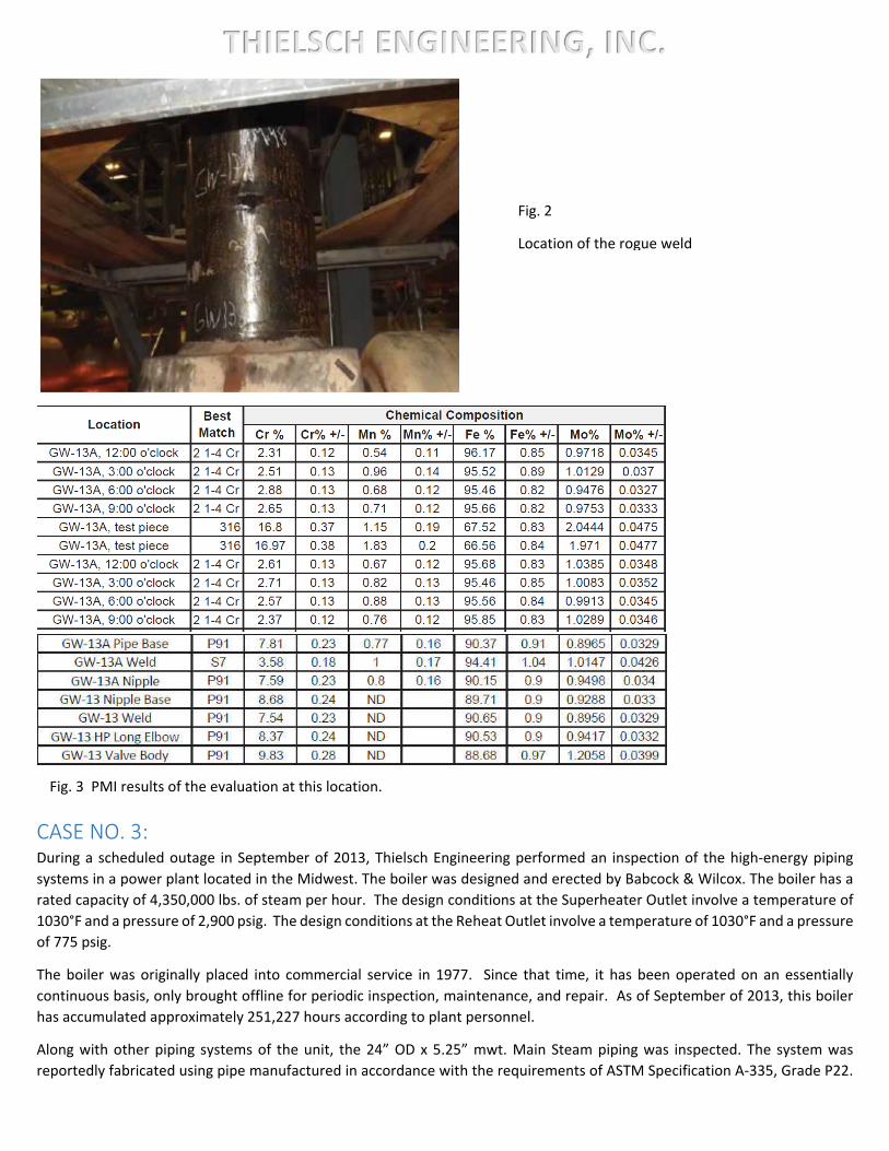
In addition to other routine metallurgical examinations, a positive material identification (PMI) was performed on the
accessible welds and base material sections of the Hot Reheat piping system using x‐ray fluorescent spectroscopy. The PMI
examination of the Hot Reheat piping system revealed that the vast majority of the locations tested were manufactured and
fabricated with the specified modified 9 Cr creep resistant ferrite steel. However, at one particular girth weld, the weld material
was consistent with 2‐1/4 Cr low alloy material. It was recommended to remove and replace the 2‐1/4 Cr material weld metal
with the proper higher grade 9 Cr filler material. While no significant service related deterioration was revealed in this rogue
weld location during the examination, it would have a significantly reduced life expectancy than the higher creep resistant
modified 9 Cr material. Fig. 1 and 2 show the location of the rogue weld. Fig. 3 shows the PMI results of the evaluation at
this location.
1‐1/4 Cr. Low Alloy Weld
A‐335 P11 Pipe Material
(1‐1/4Cr‐1/2Mo)
A‐335 P11 Pipe Material
(1‐1/4Cr‐1/2Mo)
Fig. 1
Location of the rogue weld
THIELSCH ENGINEERING, INC.
CASE NO. 3: During a scheduled outage in September of 2013, Thielsch Engineering performed an inspection of the high‐energy piping
systems in a power plant located in the Midwest. The boiler was designed and erected by Babcock & Wilcox. The boiler has a
rated capacity of 4,350,000 lbs. of steam per hour. The design conditions at the Superheater Outlet involve a temperature of
1030°F and a pressure of 2,900 psig. The design conditions at the Reheat Outlet involve a temperature of 1030°F and a pressure
of 775 psig.
The boiler was originally placed into commercial service in 1977. Since that time, it has been operated on an essentially
continuous basis, only brought offline for periodic inspection, maintenance, and repair. As of September of 2013, this boiler
has accumulated approximately 251,227 hours according to plant personnel.
Along with other piping systems of the unit, the 24” OD x 5.25” mwt. Main Steam piping was inspected. The system was
reportedly fabricated using pipe manufactured in accordance with the requirements of ASTM Specification A‐335, Grade P22.
Fig. 2
Location of the rogue weld
Fig. 3 PMI results of the evaluation at this location.

THIELSCH ENGINEERING, INC.
Utilizing visual, magnetic particle and ultrasonic phased array examinations, an extensive 360‐degree surface cracking was
identified at several of the welds involved in the scope of work.
Due to the extent and nature of the cracking revealed, further evaluation of all welds and base material sections of the Main
Steam piping system by positive material identification (PMI) was performed. The PMI examination of the Main Steam piping
revealed that 7 of the 62 girth welds included in the scope of inspection were fabricated from carbon steel weld material. This
carbon steel weld material is unsuitable for operation at 1015°F, as it does not possess the required creep‐resistant properties.
As such, the majority of these welds exhibit significant creep and fatigue deterioration.
Surface replication was performed at these rogue welds to determine the level of creep present. The microstructure of the
welds observed in replicas consisted of ferrite and pearlite grains, and carbides, not consistent with the microstructure of 2‐
1/4 Cr ‐ 1 Mo weld which normally consists of acicular bainite or bainite with limited amount of ferrite. Furthermore, the heat‐
affected zone of replicas revealed presence of fatigue cracking, creep voids, void linkage, and fissures. The atypical
microstructure of the welds as well as presence of extensive cracking and creep damage in the heat‐affected zones are
attributable to the inferior carbon steel weld metal. Fig. 1 shows the cracking conditions of one of the rogue welds from the
Main steam piping system. Fig 2 and 3 show the boat sample removal location and boat sample segment. Fig 4 and 5 show the
typical replication from the rogue welds exhibiting advanced creep.
Fig. 1
Cracking conditions of one of
the rogue welds from the
Main steam piping system

THIELSCH ENGINEERING, INC.
Fig. 2
Boat sample removal location
Fig. 3
Boat sample segment
Fig. 4
Typical replication from the
rogue welds exhibiting
advanced creep

THIELSCH ENGINEERING, INC.
All of the rogue welds were removed and repaired during the outage. Again, it is interesting to note that while these carbon
steel welds exhibited signification deterioration and damage, they operated for over 35 years at high temperature, high‐
pressure conditions.
CASE NO. 4: In February of 2006, Thielsch Engineering performed a 15,000‐hour inspection of the HP and HR piping systems of a combined
cycle unit at a Texas power facility. This inspection focused on various circumferential butt welds selected by plant personnel.
The Heat Recovery Steam Generator (HRSG) and the associated piping were designed and erected in accordance with Section
I of the ASME Boiler and Pressure Vessel Code and/or the ASME B31.1 Code on Pressure Piping covering "Power Piping". The
piping systems were fabricated using alloy steel pipe produced in accordance with ASTM Specification A‐335, Grade P91. At
the time of the inspection performed by Thielsch Engineering, the units had accumulated 18,000 operating hours.
The inspections included visual, magnetic particle and ultrasonic shear wave examinations. It also included in situ
metallographic examination (replication), hardness testing and PMI.
The PMI indicated that a significant percentage (approximately 33%) of the circumferential butt welds included in the scope of
inspection had been completed using low‐alloy steel filler material rather than modified 9 Cr filler material. (Specifically, a
number of the welds had been completed using AWS E‐8018 B2 filler material rather than AWS E‐9018 B9 filler material.)
It was concluded that, as designed, these welds were intended to have been completed using modified 9 Cr filler material and
that an error in welding quality control occurred during the field erection of the piping systems. At the applicable design
temperature, (1067̊F) the allowable stress value for 8018 B2 filler material is approximately one fifth that of the allowable
stress value for Grade P91 pipe.
Under the applicable design conditions, the erroneous substitution of low‐alloy steel filler material for modified 9 Cr filler
material would have significantly reduced the life expectancy of the circumferential butt welds. Based upon a simple
comparison of the allowable stress values, it is reasonable to assume that these circumferential butt welds with a design life
expectancy of 30 years may only have a life expectancy of 6 to 10 years.
Due to the extent of material substitution, there was good reason to believe that other field welds in these piping systems, as
well as the piping systems of the sister units at the facility were also completed using low‐alloy steel filler material. Because of
this suspicion, all of the filed welds were stripped in all four units of this facility. Approximately 40 % of field welds throughout
the other 3 units were determined to have been completed using the incorrect filler material. All of the rogue welds were
removed and replaced by Thielsch Engineering.
Fig. 5
Typical replication from the
rogue welds exhibiting
advanced creep

THIELSCH ENGINEERING, INC.
CONCLUSION: In conclusion, as plant owners and operators, the safety and integrity of the high temperature and high‐pressure components
is an uncompromising responsibility. Routine non‐destructive testing of these systems is imperative for the continued safe
operation of the unit. Thielsch Engineering has over 30 years’ experience in the inspection, maintenance and repairs of the
components associated with the safe operation of power plants. The use of positive material identification is one such
inspection technique, which is relatively simple and inexpensive, yet can ward off potentially catastrophic failures if errors in
fabrication or construction occurred. Unfortunately, the only way to know if these errors exist in your piping systems is to verify
the specified materials using positive material identification testing procedures. For more information on PMI testing please
contact Peter Kennefick at [email protected]