Thevenin's
5
INTERPRETATION OF RESULTS For the first part of the experiment, we were to identify Thevenin’s resistance and voltage across a disconnected load resistance in the circuit shown in Fig 6.1 and 6.2. Measuring the values required, it resulted to 3.33V and 8.89Ω respectively. Connecting variable load resistances in the circuit, and connecting two voltage sources as shown in Fig 6.3 we were required to measure the current and voltage that flow through the different load resistances and these values were recorded it table 6.1. From these values, it was observed that V TH and R TH are constant all through out different resistance values; 20Ω , 16kΩ , and 8.89Ω . This proves the Thevenin’s theorem which states that in the analysis of a complex resistive circuit, it is possible to replace everything except the load resistor by an equivalent circuit containing only an independent voltage source V TH in a series with a resistor R TH , and the response measured at the load resistor will remain unchanged. For the calculated values in this part, we used the formulas R TH = R 1 xR 2 R 1 +R 2 , V TH = Va −Vb ( R 2 R 2+ R 1 ) , I R1 = VTH R 1+ RTH and V R1 = VTH ( R 1 RTH + R 1 ) . Values calculated were observed to be approximately equal to the measured values which mean that the experiment was done accurately. Values were recorded in the calculated values section in Table 6.1. For the second part of the experiment, we were to identify Norton’s resistance and current. We replaced the open circuit with an ammeter as shown in Fig 6.4 and the measured value was denoted as the Norton Current I N . Norton resistance was measured the same value as the Thevenin resistance and it resulted to 6.15Ω. Connecting different load resistance values in the circuit as that in the first part of the experiment, we were to measure IR1 and VR1 and we used the simulation to identify its values and these values were recorded in Table 6.2. From these values it was observed that I N and R N are also constant. This shows the principle of Norton’s theorem which states that a complex resistive circuit can be changed into an equivalent circuit (except the load) which consists of an equivalent resistance R N connected in parallel with an independent source I N . For the calculated values in this part of the experiment, we used the formulas R N = R 3 xR 3 R 2 +R 3 , I R1 = ¿ ( RN R 1+RN ) , and V R1 = ¿ R 1 xRN R 1 +RN . Values calculated were also
-
Upload
angel-mallari -
Category
Documents
-
view
145 -
download
3
Transcript of Thevenin's
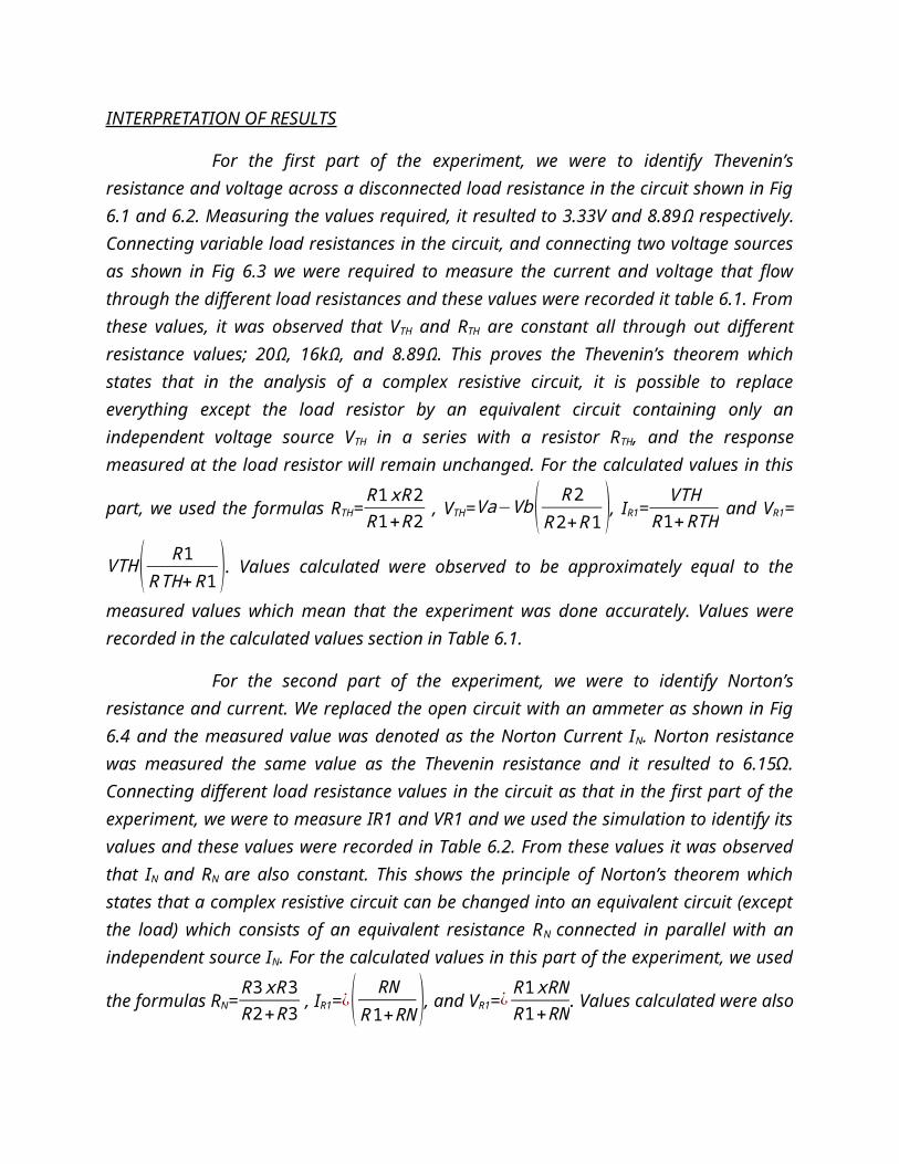
INTERPRETATION OF RESULTS
For the first part of the experiment, we were to identify Thevenin’s resistance and voltage across a disconnected load resistance in the circuit shown in Fig 6.1 and 6.2. Measuring the values required, it resulted to 3.33V and 8.89Ω respectively. Connecting variable load resistances in the circuit, and connecting two voltage sources as shown in Fig 6.3 we were required to measure the current and voltage that flow through the different load resistances and these values were recorded it table 6.1. From these values, it was observed that VTH and RTH are constant all through out different resistance values; 20Ω, 16kΩ, and 8.89Ω. This proves the Thevenin’s theorem which states that in the analysis of a complex resistive circuit, it is possible to replace everything except the load resistor by an equivalent circuit containing only an independent voltage source VTH in a series with a resistor RTH, and the response measured at the load resistor will remain unchanged. For the calculated values in this part, we used the
formulas RTH=R1 xR2R1+R2 , VTH=Va−Vb( R2
R2+R1 ), IR1=VTH
R1+RTH and VR1=
VTH ( R1RTH+R1 ). Values calculated were observed to be approximately equal
to the measured values which mean that the experiment was done accurately. Values were recorded in the calculated values section in Table 6.1.
For the second part of the experiment, we were to identify Norton’s resistance and current. We replaced the open circuit with an ammeter as shown in Fig 6.4 and the measured value was denoted as the Norton Current IN. Norton resistance was measured the same value as the Thevenin resistance and it resulted to 6.15Ω. Connecting different load resistance values in the circuit as that in the first part of the experiment, we were to measure IR1 and VR1 and we used the simulation to identify its values and these values were recorded in Table 6.2. From these values it was observed that IN and RN are also constant. This shows the principle of Norton’s theorem which states that a complex resistive circuit can be changed into an equivalent circuit (except the load) which consists of an equivalent resistance RN connected in parallel with an independent source IN. For the calculated values in this part of the experiment, we used the
formulas RN=R3 xR3R2+R3 , IR1=¿( RN
R1+RN ), and VR1=¿ R1 xRNR1+RN . Values calculated
were also approximated to be equal to the measured values which mean

that the experiment was done correctly. Values were recorded in the calculated values section in Table 6.2.
CONCLUSION
From the results we have gathered, Thevenin’s theorem and Norton’s theorem were proven.
In a complex resistive circuit, components may be manipulated in a way that a part of the circuit may be turned into a simpler circuit with an independent voltage source and a resistance in series with it which may be called Thevenin voltage and resistance. Thevenin voltage is also called the open circuit voltage and the Thevenin resistance is the resistance looking back across two hanging nodes when all independent voltage sources in the circuit are zero.
Moreover, a complex circuit may also be turned into a simpler circuit with an independent current source and a resistance in parallel to it which is the Norton current and resistance. Norton current is the short circuit current and Norton resistance is the same as the Thevenin resistance.
QUESTIONS AND PROBLEMS
1. What technique is applied to determine an equivalent circuit from another equivalent circuit?
Source transformation.
2. What does a “dead circuit” in Thevenin’s and Norton’s Theorem mean? A dead circuit is a circuit in which all the independent sources in a
certain circuit are turned off. Thus, an independent voltage source could be represented by a short circuit while and an independent current source is represented by an open circuit when it is set to inactive mode.
3. How is a “dead circuit” analyzed through Thevenin’s Theorem? The circuit is analyzed as the Thevenin’s voltage is equal to the
voltage across a parallel resistor this is applicable when there is no dependent source present on the circuit while if there is a dependent source, an independent source should be placed on the Load terminal to get the RTH.
4. How is a “dead circuit” analyzed through Norton’s Theorem? In Norton’s Theorem the circuit is shorted bypassing some of the
resistances which depends on the circuit.
5. What are the limitations of the Thevenin’s and Norton’s Theorem? The Thevenin’s and Norton’s Theorem could only be applied when
the circuit is Linear which thus, it should apply the linearity property.

6. Determine the Thevenin equivalent circuit and Norton equivalent circuit shown in the figure below.
Supermesh 1 and 2
0= 25 I1 + 130 I2
KCL
20- I1 + I2= 0
I1= -16.77A
I2=3.23A
Vth+25 (-16.77)+ 3.23(130) = 0
Vth= -0.65 V
Rth = 140||15 + 8 = 21.55 Ohms
7. Determine the Thevenin equivalent circuit and the Norton equivalent circuit shown in the circuit below.
Mesh 1: 42000 I 1−2000 I 2=−5Vx
V X=2000 I2−2000 I 1
KCL: I 1+ I 2=3 x 10⁻³
Thus, Vx = VTH =10V
Assume 1V source then KVL1+5V X−V X=0
V X=0.25V
KVL: 5V X−V X−40000Ω(I )=0
I=0.1mA
RTH=RN = 1 / I = 10000
IN=V TH
RTH= 10V10 ,000Ω
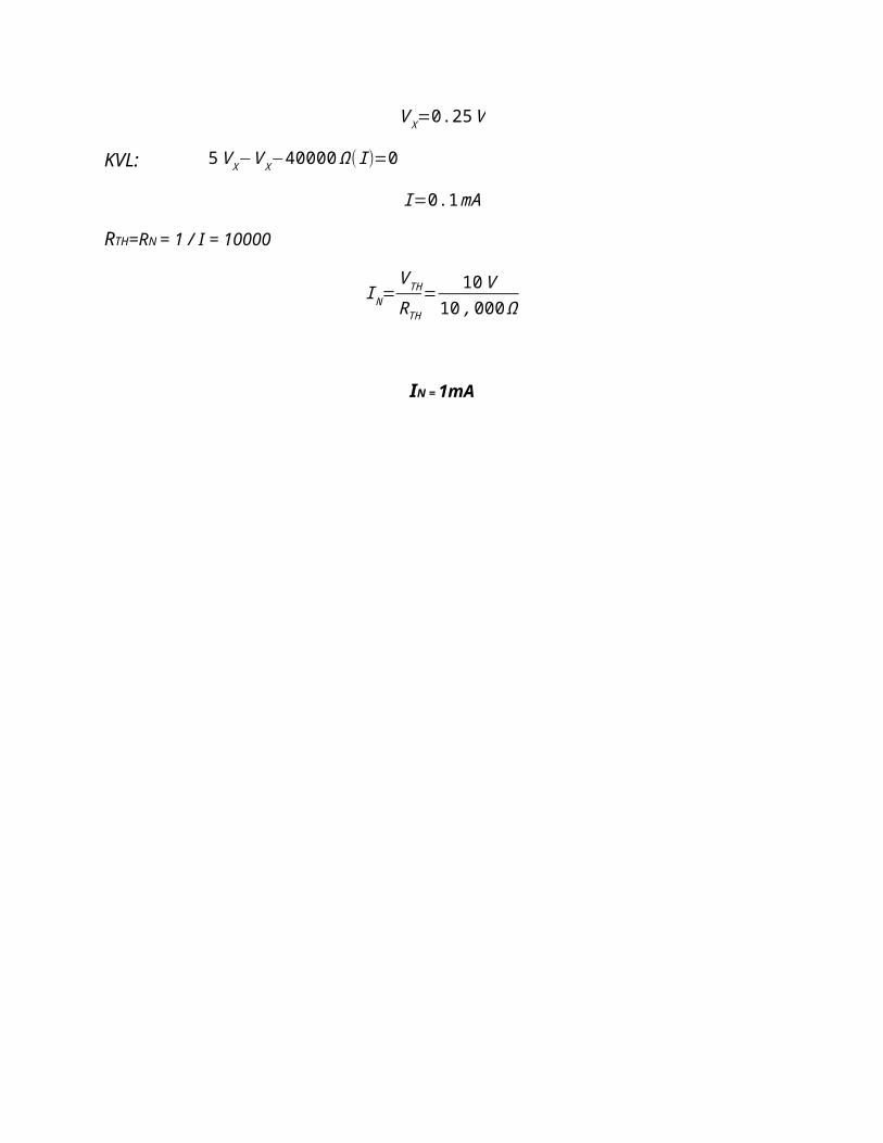
IN = 1mA