
TheUltimaker2GUIDE
33
2 THE ULTIMAKER ULTIMATE MAKER’S GUIDE
-
Upload
adam-mahardy -
Category
Documents
-
view
98 -
download
0
Transcript of TheUltimaker2GUIDE

2THEULTIMAKERULTIMATE MAKER’S GUIDE

THE NAVIGATION
THE CREDIT.....................................................................................................................................................................................................i
THE MACHINE...............................................................................................................................................................................................ii
THE TERMINOLOGY...................................................................................................................................................................................iii
MATERIAL QUALITY...................................................................................................................................................................................iv
THE MATERIALS..........................................................................................................................................................................................01
THE ATOMIC METHOD............................................................................................................................................................................05
REPLACING THE NOZZLE........................................................................................................................................................................07
TROUBLESHOOTING PRINTS.................................................................................................................................................................09
INSIDER TIPS + TRICKS.............................................................................................................................................................................22
MAKER NOTES...........................................................................................................................................................................................25
MORE #MAKER?................................................................................................................................................................................28
THE ULTIMATE MAKERS GUIDE NAVIGATIONi

THIS GUIDE IS AN ADDITIVE COLLABORATION BETWEEN...
+
THE ULTIMATE MAKERS GUIDE CREDITi
GUIDE COMPILED BY: ADAM MAHARDY
AUTHORED BY: 3DVERKSTAN

THE MACHINE
THE ULTIMATE MAKERS GUIDE THE MACHINEii

THE TERMINOLOGY
THE ULTIMATE MAKERS GUIDE LINGO iii
THE MATERIAL QUALITY
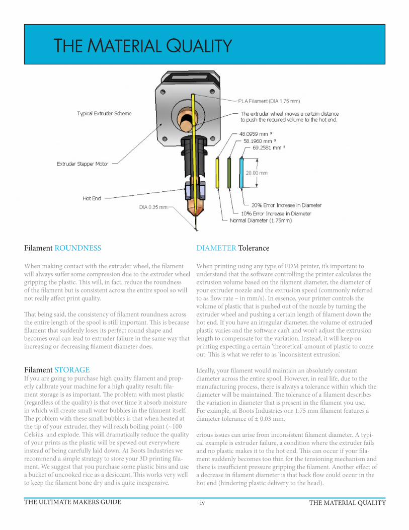
DIAMETER Tolerance
When printing using any type of FDM printer, it’s important to understand that the software controlling the printer calculates the extrusion volume based on the filament diameter, the diameter of your extruder nozzle and the extrusion speed (commonly referred to as flow rate – in mm/s). In essence, your printer controls the volume of plastic that is pushed out of the nozzle by turning the extruder wheel and pushing a certain length of filament down the hot end. If you have an irregular diameter, the volume of extruded plastic varies and the software can’t and won’t adjust the extrusion length to compensate for the variation. Instead, it will keep on printing expecting a certain ‘theoretical’ amount of plastic to come out. This is what we refer to as ‘inconsistent extrusion’.
Ideally, your filament would maintain an absolutely constant diameter across the entire spool. However, in real life, due to the manufacturing process, there is always a tolerance within which the diameter will be maintained. The tolerance of a filament describes the variation in diameter that is present in the filament you use. For example, at Boots Industries our 1.75 mm filament features a diameter tolerance of ± 0.03 mm.
erious issues can arise from inconsistent filament diameter. A typi-cal example is extruder failure, a condition where the extruder fails and no plastic makes it to the hot end. This can occur if your fila-ment suddenly becomes too thin for the tensioning mechanism and there is insufficient pressure gripping the filament. Another effect of a decrease in filament diameter is that back flow could occur in the hot end (hindering plastic delivery to the head).
Filament ROUNDNESS
When making contact with the extruder wheel, the filament will always suffer some compression due to the extruder wheel gripping the plastic. This will, in fact, reduce the roundness of the filament but is consistent across the entire spool so will not really affect print quality.
That being said, the consistency of filament roundness across the entire length of the spool is still important. This is because filament that suddenly loses its perfect round shape and becomes oval can lead to extruder failure in the same way that increasing or decreasing filament diameter does.
Filament STORAGEIf you are going to purchase high quality filament and prop-erly calibrate your machine for a high quality result; fila-ment storage is as important. The problem with most plastic (regardless of the quality) is that over time it absorb moisture in which will create small water bubbles in the filament itself. The problem with these small bubbles is that when heated at the tip of your extruder, they will reach boiling point (~100 Celsius and explode. This will dramatically reduce the quality of your prints as the plastic will be spewed out everywhere instead of being carefully laid down. At Boots Industries we recommend a simple strategy to store your 3D printing fila-ment. We suggest that you purchase some plastic bins and use a bucket of uncooked rice as a desiccant. This works very well to keep the filament bone dry and is quite inexpensive.
THE ULTIMATE MAKERS GUIDE THE MATERIAL QUALITYiv

- Print temperature: 200-220C- Bed temperature: 50-70C- Glass Transition Temperature: 55C- MSDS
Similarly to ABS, PLA comes in a huge selection of colours, both opaque and trans-parent/semi-transparent versions.
Unlike ABS it cannot be vapour polished with Acetone. There are chemicals that can do a similar job but we cannot recommend it as the chemicals are really nasty to work with.
PLA can be polished using wet sand paper and hard work followed by polishing pastes. Keeping the print cool while sanding is essential as PLA is fairly temperature sensitive as previously mentioned. If you let the print get too hot while sanding it will go gummy and your hard work will be ruined. That said, we have used a power sander on PLA without issues. But we did use lots of water while doing so.prettier. It’s probably a good idea to practice this on some scrap pieces first to get a feel for the process.
When sanding a print the surface of the print can become white(ish), rubbing the surface with some vegetable oil can help reduce this effect.
Generally you don’t need a higher bed temperature than 60C but if you’re printing things with a very big bottom surface you might want to increase the temperature a bit to help keep the corners down. Also enable brim if you’re having trouble with lifting.
ABS is good when you need a print that has a bit more give than PLA and is more heat resistant. A very simplified way to look at it is that PLA is a very hard plastic that tends to snap when it breaks and ABS is a bit softer and tends to bend before breaking. It also has a higher glass transition temperature than PLA which means it it more suitable for hot situations like the inside of a car during summer. On the downside it can be a bit trickier to print as it tends to shrink more than PLA and it also has a nastier smell while printing.
For glueing ABS parts you can create a make shift glue by dissolving pieces of ABS into Acetone and then using the resulting slurry as a glue. A similar slurry can be used to spread on the print bed to aid with bed adhesion if you need parts to stick even better than the glue stick. To create the slurry you simply dissolve about 1/3 ABS into 2/3 Acetone in an air tight container. To speed up the process it is help-ful to grind up the plastic into smaller parts. Once all the plastic has dissolved the resulting slurry can be used as a glue that will chemically bond two prints together. Apply the slurry to the parts and then press them together. The Acetone in the mix will melt the surface of the prints and as the Acetone evaporates you are left with a very strong bond.
-Print temperature: 220-260C-Bed temperature: 90-110C-Glass Transition Temperature: 78C
PLA/PHA - poly lactic acid
ABS - acrylonitrile butadiene styrene
THE ULTIMATE MAKERS GUIDE THE MATERIALS01
THE MATERIALS

- Print temperature: 200-220C- Bed temperature: 50-70C- Glass Transition Temperature: 55C- MSDS
A formulation of PLA intended for producing professional, high quality, 3D printed parts. It features a visually distinct finish, with a more vibrant, opaque coloration, than standard PLA. PRO Series PLA is made in the USA and is produced to a more precise specification. It is available in 1.75mm and 3mm.
A formulation of ABS intended for producing professional, high quality, 3D printed parts. It features a visually distinct finish, with a more vibrant, opaque coloration, than standard PLA. PRO Series PLA is made in the USA and is produced to a more precise specification. It is available in 1.75mm and 3mm.
Useful for printing rubber-like parts that can bend or flex. It is compatible with almost all desktop 3D printers. Soft PLA is available, as an individual spool or as a sampler pack of each color, in both 1.75mm and 3mm.
A wood-like 3D printing material that gives 3D printed objects the look and feel of fiberboard. It also imbues parts with other wood-like attributes, such as the ability be cut, painted, and sanded. It is also possible to give parts printed in LAYWOO-D3 a simulated alternating light/dark wood-grain appearance by varying the tempera-ture during printing. LAYWOO-D3 is available in a 1.75mm or 3mm unspooled rolls.
-Print temperature: 220-260C-Bed temperature: 90-110C-Glass Transition Temperature: 78C
-Print temperature: 220-260C-Bed temperature: 90-110C-Glass Transition Temperature: 78C
PRO SERIES PLA - poly lactic acid
PRO SERIES ABS - acrylonitrile butadiene styrene
FLEXABLE PLA -poly lactic acid
LAYWOOD
THE ULTIMATE MAKERS GUIDE THE MATERIALS02

Is a 3D printing material that gives parts the look and feel of grey stone while retain-ing the resiliency of plastic, making it ideal for landscape and architectural designs. Anything made with LAYBRICK can be painted and sanded. In the lower range of 165°C to 190°C, the print will come out mostly smooth, whereas with higher tem-peratures it will begin to have a more pitted, sandstone-like texture. LAYBRICK is available in both 1.75mm and 3mm unspooled rolls.
Is a versatile 3D printing material which prints as a bright natural to white with a translucent surface, and can absorb color added post process with most common, acid-based clothing dyes. Unprinted Nylon is extremely sensitive to moisture, so taking drying measures during storage and immediately prior to printing is highly recommended for optimal results. Taulman 618 is a 3D-printingspecific formula-tion of Nylon that comes in a variety of sizes and packages, including 1-, 2-, and 3-packs of both 1.75mm and 3mm.
Is a flexible 3D printing material that feels and acts much like flexible rubber. TPE can be used to make parts that can bend or must flex to fit their environment - stop-pers, belts, springs, phone cases and more. This extremely flexible material will allow you to create prints that will have the properties of a soft rubber, making it even more flexible and elastic than our Soft PLA filament. TPE is available in 1.75mm and 3mm.
Is a modified version of our standard ABS filament which has a resistance of 1200 ohm/cm. This filament works with all ABS compatible 3D printers. Conductive ABS filament is available in 1.75mm and 3mm.
LAYBRICK
NYLON
TPE
Conductive ABS Filament
THE ULTIMATE MAKERS GUIDE THE MATERIALS03

Is very similar to ABS. The main difference is that HIPS uses Limonene as a solvent. HIPS is as easy to print with as ABS but is much less likely to warp. HIPS is available in 1.75mm and 3mm.
A formulation of PLA intended for producing professional, high quality, 3D printed parts. It features a visually distinct finish, with a more vibrant, opaque coloration, than standard PLA. PRO Series PLA is made in the USA and is produced to a more precise specification. It is available in 1.75mm and 3mm.
Useful for printing rubber-like parts that can bend or flex. It is compatible with almost all desktop 3D printers. Soft PLA is available, as an individual spool or as a sampler pack of each color, in both 1.75mm and 3mm.
-Print temperature: 220-260C-Bed temperature: 90-110C-Glass Transition Temperature: 78C
HIGH IMPACT POLYSTYRENE - (HIPS)
PVA - Polyvinyl Acetate
FLEXABLE PLA -poly lactic acid
THE ULTIMATE MAKERS GUIDE THE MATERIALS04
NEW MATERIALS ARE INNOVATED EVERY DAY. Please, check online for the most accurate up-to-date availabilities.

THE ATOMIC METHOD
THE ULTIMATE MAKERS GUIDE THE ATOMIC METHOD05

THE ULTIMATE MAKERS GUIDE THE ATOMIC METHOD06
Use the Atomic Method described below to clean your hotend thoroughly from the inside. This can be necessary if you are experiencing underextrusion and/or if you have some debris/carbonized plastic in the nozzle. A common cause for this is if the hotend has been sitting hot for some time without extruding.

REPLACING THE NOZZLE
THE ULTIMATE MAKERS GUIDE REPLACING THE NOZZLE07
First it should be noted that the nozzle of the UM2 is integrated into the heater block and the two can not be separated. This is different from the Ultimaker Original where the nozzle is a separate piece that you can easily remove by heating the print head to printing temperature and simply unscrewing it with a wrench of other suitable tool. For simplicity we will refer to the nozzle+heater block combination of the UM2 as “nozzle” in this guide.
First remove the filament and then start by removing the fan shroud by unscrewing the four screws that hold it in place. There are two screws on each side. Be ready to catch those little buggers as they have a tendency to bounce around and get lost if you drop them. Once the screws are removed you can slide the fan shroud off the head. Use a piece of tape to keep it out of the way. If your printer is turned on, be careful that you don’t poke something into the third fan on the head.
You can now start to unscrew the nozzle by inserting a small screwdriver into one of the holes in the ring indicated below and turning anti-clockwise. Be careful here and only use moderate force. If it does not move it means that there is plastic in the threads keeping the ring in place. You will have to heat up the print head to soften the plastic, around 100C will likely do the trick. Once heated it should be fairly easy to rotate the ring. Keep turning the ring until the nozzle drops out. Remember that the nozzle is very hot so make sure you don’t try to catch it or allow it to touch any of the plastic parts of the print head.
There are two screws on each side.
You might notice some brown residue that looks almost like rust underneath this ring. Don’t worry, it is not rust but copper grease that was put there intentionally
Taping the shroud out of the way is optional but it does help.

THE ULTIMATE MAKERS GUIDE 08
You will now have access to the screw that locks the heater cartridge and temperature sensor in place. Use one of the allen keys that were supplied with your printer to unscrew it. Be careful when removing the heater and sensor as it is easy to break the wires if you use too much force. If they wont budge you can try turning up the heat. The thermal expansion of the parts should help you get the parts loose.
To re-assemble, simply reverse the steps above. Be careful when tightening the set screw, it should be snug enough to prevent the heater and sensor from moving, but don’t over tighten as you might damage them.
There are two screws on each side. The larger part on the left is the heater cartridge.
REPLACING THE NOZZLE
TROUBLESHOOTING PRINTS
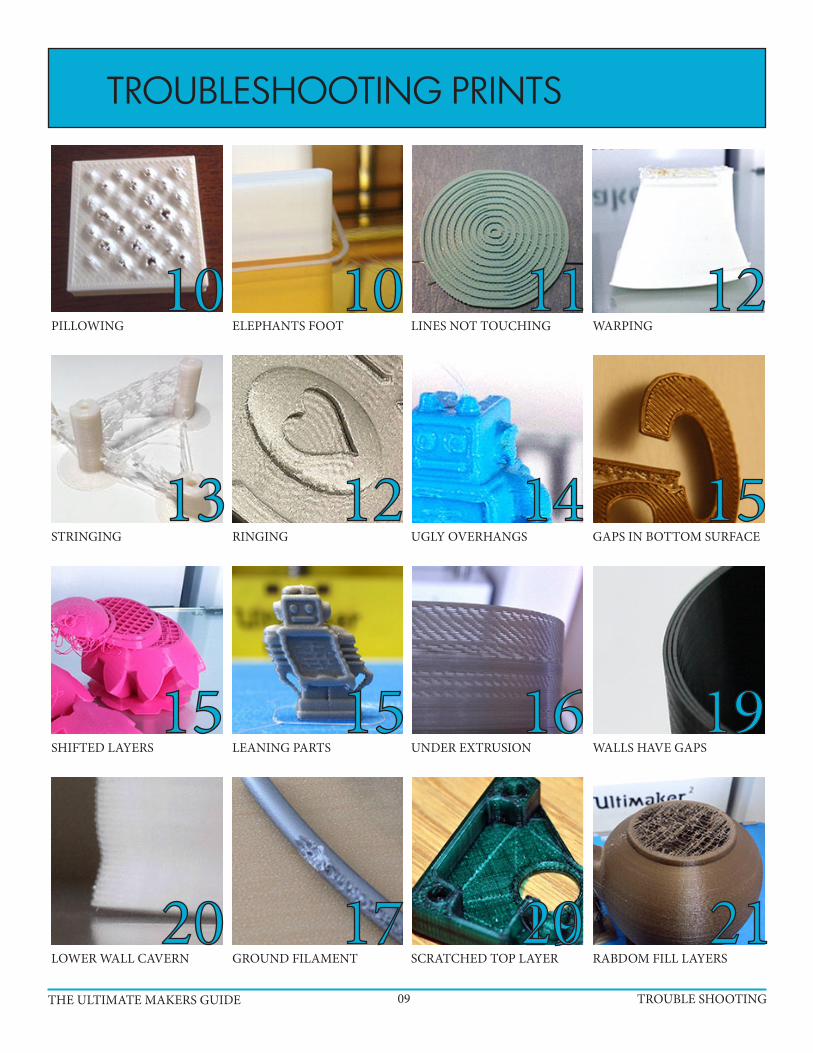
PILLOWING
STRINGING
SHIFTED LAYERS
LOWER WALL CAVERN
ELEPHANTS FOOT
RINGING
LEANING PARTS
GROUND FILAMENT
LINES NOT TOUCHING
UGLY OVERHANGS
UNDER EXTRUSION
SCRATCHED TOP LAYER
WARPING
GAPS IN BOTTOM SURFACE
WALLS HAVE GAPS
RABDOM FILL LAYERS
THE ULTIMATE MAKERS GUIDE TROUBLE SHOOTING09
10 10 11 12
13 12 14 15
15 15 16 19
20 192017 21

THE ULTIMATE MAKERS GUIDE TROUBLE SHOOTING10
Pillowing show up as bumps in the top surface of a print and can either be open or closed. The most important thing here is to make sure that your cooling fans are going top speed when the printer is laying down the top layer. Without proper cooling the thin strands of plastic tend to curl up and stick up above the surface of the print and make it harder for subsequent layers to properly span over the gap. With good cooling the strands gradu-ally grow over the gaps until it closes fully.
Besides cooling you also need to print a thick enough top surface so that the printer can properly close it. In general you should make sure that you are printing at least six top layers. Since the top and bottom thickness is set in mm you will have to do some basic math to make sure you’re printing enough layers. If you are printing with a 0.1mm layer height you should make your top thickness at least 0.6mm.
In general you will need more top layers the thinner your layer height is. With very thin layers the thin strands of plastic are more likely to break before fully bridging over the gaps in the infill and providing a nice base for the following layer. You will therefore need to print more layers to make up for this. In other words very thin layers can be another cause of pillowing.
This image shows two prints done with exactly the same settings, except for one, the bottom print did not have the cooling fans enabled.
Some users have also reported that the change in infill pattern between 24% and 25% (and up) makes a big difference. The difference between infill percentages at 24 or lower and 25 and higher is how cura lays down each layer.
It’s very common that the first couple of layers of a print is wider than you expected them to be. This is because you will generally want to make sure the first layer is nicely squished into the build platform so that it sticks properly. By doing this the plastic gets squished out into a thicker line than normal and thus the bottom of the print will bulge out a bit like an ele-phant’s foot. You can decrease this effect by levelling your bed so that the nozzle is slightly further away from the bed and lowering the bed tempera-ture a bit. It’s hard to get rid of this effect entirely without sacrificing bot-tom layer quality and bed adhesion. It will be easier on small prints as they are less likely to warp and detach from the platform and you can therefore get away with not squishing the first layer as hard.
However, if you are the one who created the part there is a trick you can use to help get rid of this problem. Simply put a small chamfer on the bottom of your print.
PILLOWING - Top surfaces are not closed properly or come out bumpy.
ELEPHANTS FOOT - The lowest layers of the print flare out.

A fairly common issue on the Ultimaker Original in particular (especial-ly the kit versions) is that people try to print things with circles and the circles don’t come out perfectly circular. At the same time infill lines are not touching the outside perimeter properly. You may also see that infill lines are grouped in pairs where two lines are touching followed by a gap and then another two lines touching. Both of these problems stem from the same issue and that is backlash caused by slack belts. Mainly it is the so called “short belts”, which are the belts that are connected to the stepper motors, not being tight enough. Thankfully this is an easy fix.
This image is a nice example of lines grouped in pairs. Notice that there are actually two lines very close together followed by a gap and then another two lines close together.
To make sure the belts are tightened properly you need to loosen the four screws that hold the stepper motor in place. Don’t remove the screws fully, just loosen them so that you can move the stepper motor up and down.
Now press down firmly on the top of the motor so that the belt is nice and tight. While keeping pressure on the motor re-tighten the screws to lock the motor in place. Do this for both motors.
It’s also a good idea to make sure that the rods are nicely lubricated. A sin-gle drop of light oil, such as sewing machine oil, on each rod is enough.
An additional step you might want to take while you’re at it is to ensure that the set screws of the pulley on the motor is nice and tight, tighter than you might think should be enough.
IRREGULAR CIRCLES/LINES NOT TOUCHING - Circles and lines are not properly touching. Come out bumpy.
THE ULTIMATE MAKERS GUIDE TROUBLE SHOOTING11

Warping happens when the plastic cools and contracts. As the print cools down and shrinks slightly it starts to pull in on itself. Eventu-ally the forces become so great that the print bends up from the platform. The best way to prevent this is with a heated build platform. By using a heated platform the plastic is kept just below the point where it goes solid, the so called glass transition temperature, and it therefore stays flat and connected to the platform. Although the heat from the platform is often enough it is also recommended to add a thin layer of glue to the platform to promote adhesion. Your printer will have come with a small stick of glue, spread a thin layer of glue onto the platform. Then, with a moistened rag or piece of paper, spread the glue out evenly onto the platform. As the bed heats the water will evaporate and leave a very nice thin and even layer of glue.
It is also important to make sure your bed is levelled as perfectly as you can. The plastic must be squished onto the platform so that it bonds properly. Besides preventing the print from coming loose or warping it also makes the bottom layer nice and shiny. You want the lines to be touching each other and all look identical to each other. Here’s an example of what you’re looking for:
Notice how all the lines are uniform and touching. If the lines show signs of gaps your bed is levelled too low. If the lines are squished and messy it is likely your bed is too close.
A built in feature in cura called “brim” is another great way to help keep your print from warping. This feature puts what looks like the brim of a hat on the bottom layer of your print to help fight against the pulling forces of the cooling print. Since this brim is only a sin-gle layer thick it is very easy to remove once the print is complete.
Dealing with ABS
ABS is much more prone to warping than PLA and needs some extra care. Besides needing a higher bed temperature (remember to change the material setting on your machine to ABS) you also need to be more careful with cooling. If at all possible try to print without using the cooling fans at all. Ideally the printer should be enclosed to keep a constant temperature in the printing area. To promote bed adhesion you can make a slurry of ABS by dissolving a few bits of scrap ABS in a jar with Acetone Spread this slurry like a glue onto your build platform.
Ringing is what we call the small waves or shadows that usually appear around sharp corners on a print. It’s often very apparent if you have text on your print as you will see what looks like shad-ows of the text. This happens when the print head makes a sudden direction change and the inertia of the head causes vibrations that show up in the print. To combat this there’s a couple of things you can do. Simply slowing down your print speed will help lessen the effect. Decreasing the acceleration of the printer will make a big impact on the reduction of ringing without affecting print speed too heavily. You adjust this setting by going into the advanced settings on the printer itself Maintenance -> Advanced -> Motion settings. Try 3000 or 1500 and see how that affects your print.
Excessive temperature can also cause strange vertical lines in a print. Try lowering the temperature slightly and see if that helps.
WARPING - Corners of the print lift and detach from the platform.
RINGING - Waves/shadows appear in the print.
THE ULTIMATE MAKERS GUIDE TROUBLE SHOOTING12

The primary countermeasure for stringing is something called retraction. When you have retraction enabled the printer will “suck” the filament back a short distance before moving the print head over an open space. By sucking the filament in a bit it helps prevent plastic from dripping from the nozzle during the travel move.
So what you should do first is to make sure that retraction is actually enabled in cura. This setting is found on the “Basic” tab in the form of a checkbox when you are in the full settings mode (Expert -> Switch to full settings...). Make sure this box is checked. You can check if retractions will happen without printing by looking at the layer view in cura after slicing your object. You switch to layer view with the big button in the upper right corner of the window. The retractions are indicated by small blue lines that go from the print and straight up. It can sometimes be tricky to see these lines without zooming in and rotating the view around.
Another thing you can do to lessen the effect of stringing is to increase the travel speed. By default the travel speed is set to 150mm/s but you can increase this to 250mm/s. By increasing the travel speed you give the head less time to ooze plastic but you also help snap off any strands that form instead of dragging them along.
Temperature can also play a part. Experiment with a lower temperature.
As you can see it can be hard to spot these small lines unless you zoom in for a closer look. The other blue line indicates the travel move that the retraction is preparing for.
This image shows clearly how lowering the temperature has a very positive effect on the amount of stringing. As always when lowering temperature you must also make sure that you are printing slowly enough to prevent under extrusion. Note that the temperatures shown in this image is for PLA, for other materials you may not be able to go this low. Or conversely, you may be able to go even lower.
On the Ultimaker2 the speed and length of the retraction is set on the printer. The default values work well but feel free to play around. Increasing the retraction length for example can make up for sloppiness in the connection of the bowden tube to the print head.
Finally it should be noted that some filaments are simply prone to stringing and no matter what you do it might be all but impossible to completely eliminate them. Even different colours from the same manufacturer can differ in how much they string.
STRINGING - Corners of the print lift and detach from the platform.
THE ULTIMATE MAKERS GUIDE TROUBLE SHOOTING13

The reason overhangs come out uglier than a straight wall is simply because new layers are not properly supported by the preceding layer. Rather than fully resting and being anchored in place by the previous layer the new layers are partially printed into mid air and tend to sag down slightly or curl up. Sometimes these issues accumulate making each layer worse than the last. Curling around corners when using thin layers seems to be especially problematic. Dealing with overhangs is tricky, there are many variables that will affect how well or badly they will be printed. Temperature, print speed, amount of overhang, layer height, material, and cooling all play a part in how an overhang will print.
Like so many other things cooling plays one of the biggest roles in how well an overhang will print. Ensure that your cooling fans are going 100% when the overhang is being printed. If the object you’re trying to print is small there’s a chance that, due to the way the nozzle is positioned, the right fan never gets a chance to properly cool the print. A prime example of this is the right ear of the Ulti-maker robot. A way around this is to print more than one object at the same time. By doing this the print head will move between the two objects and allow the layer of one object cool down while the same layer is being printed on the other copy. This also helps greatly
UGLY OVERHANGS - The lower surface of overhangs come out ugly.
THE ULTIMATE MAKERS GUIDE TROUBLE SHOOTING14
when the layer currently being printed is very small. When printing very small details such as the antennas on the Ultimaker robot the print head will stay over the same spot for quite some time and transfer a lot of heat into the print which will deform the layer quite badly.
Another variable is layer height. Depending on your print, sometimes a thicker layer height will be helpful in improving the quality and some-times a thinner layer is helpful. Thinner layers seem to create a more pronounced upward curling of the edges and especially around sharp corners. You’ll simply have to experiment and see what works best in your situation.
Print speed will also affect your print quality. Slowing down will usually always result in an improvement.
Try to reduce the print temperature as much as possible without causing under extrusion. The slower you print the lower your print temperature can be. In addition to reducing the print temperature it can be worth lowering the print bed temperature, or even turning it off completely. This is especially important if the overhang is close to the bed.
The top object has an overhang that can be quite hard to get a nice clean surface on. The bottom object has replaced the overhang with a straight “roof ” that can instead be bridged which can produce a cleaner result in some cases. Bridging is when the print head will print straight across a gap between two islands into mid air. This actually works better than you might think, especially if the jump is short.
There is a limit to how much of an overhang you can print while still preserving the quality you want and this is simply a limitation of the type of printer the Ultimaker is. Where this line is drawn depends on your own expec-tations, what plastic you are using, what the geometry of the overhang is, how well it can be cooled and many other factors.

If the bottom layer of your print is showing very obvious print lines it’s likely that your bed is simply levelled a little bit too far away from the nozzle. The closer to the nozzle the bed is on the first layer the harder the plastic will be squished into the bed and the lines will then blend togeth-er better. However, you can’t go too closely as that will prevent the plastic from escaping from the nozzle properly. Pressure will build up and even-tually the plastic will squirt out and create an ugly blob, or, it could cause the feeder to grind your filament which is something you don’t want.
By default cura will print a 0.3mm thick first layer. You may want to try reducing this to 0.2mm or even 0.1mm to make the bottom layer even more of a mirror like surface. However, when you reduce the initial layer height you must be very precise in your bed levelling. A 0.3mm layer height is quite forgiving, a 0.1mm layer height is anything but.
If the printer suddenly shifts the layers it is most likely that one or more pulleys are not secured properly to the axis/axes. To confirm that this is the case you can use a black marker and put marks on the pulleys and a matching mark on the axes. After printing a test print and seeing a layer shift you can then inspect your marks and see which pulley(s) have moved. It is likely that the pulley(s) that need tightening are those con-nected to the short belts. Tighten the set screws that hold the pulleys in place very tightly, probably a bit tighter than you expect. The small allen key that came with your printer will flex as you tighten the screws.
It could also be that the part you are printing detached from the platform during the print. This should be fairly easy to see as the part will have shifted position from where it was originally.
In rare cases there could be an issue with end stops triggering unexpect-edly due to cross talk between wires. Re-routing the cables can help with this. But again, this is a very rare occurrence.
A leaning print is usually caused by friction causing the print head to move a shorter distance than expected. Make sure that the short belts that connect the stepper motors to the axes do not rub up against the main body of the printer. Similarly make sure that the pulleys on the stepper motors that the belts ride over are not touching the side of the printer. If they are you must move the pulley closer to the stepper motor.
It is difficult to reach the set screws that secure the pulley to the motor and you will therefore have to remove the white cover plates that the motors sit behind. These panels are held in place with a single screw on the side of the machine if you have a slightly older printer. On the newer ones there are two screws, one on the back and one on the side. Remove the screw and then lift the covers off by tilting the cover slightly towards the front and them lifting them out. The only thing holding them in place is a small metal tab at the bottom of the cover that sticks down into the bottom of the printer.
GAPS IN SURFACE LAYER- Lines are overly visible or spaced apart on the first layer
SHIFTED LAYER - Parts of the print suddenly shift along the X or Y axis.
LEANING PRINTS - Prints gradually lean over or become skewed
THE ULTIMATE MAKERS GUIDE TROUBLE SHOOTING15
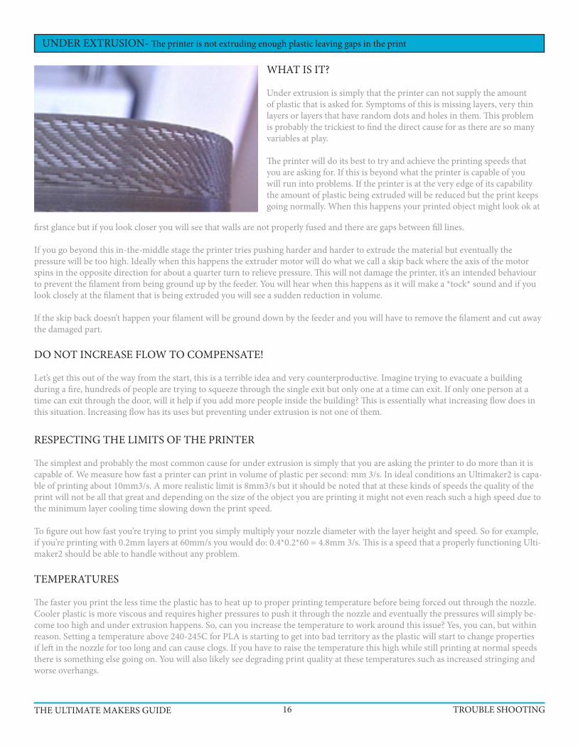
WHAT IS IT?
Under extrusion is simply that the printer can not supply the amount of plastic that is asked for. Symptoms of this is missing layers, very thin layers or layers that have random dots and holes in them. This problem is probably the trickiest to find the direct cause for as there are so many variables at play.
The printer will do its best to try and achieve the printing speeds that you are asking for. If this is beyond what the printer is capable of you will run into problems. If the printer is at the very edge of its capability the amount of plastic being extruded will be reduced but the print keeps going normally. When this happens your printed object might look ok at
UNDER EXTRUSION- The printer is not extruding enough plastic leaving gaps in the print
THE ULTIMATE MAKERS GUIDE TROUBLE SHOOTING16
first glance but if you look closer you will see that walls are not properly fused and there are gaps between fill lines.
If you go beyond this in-the-middle stage the printer tries pushing harder and harder to extrude the material but eventually the pressure will be too high. Ideally when this happens the extruder motor will do what we call a skip back where the axis of the motor spins in the opposite direction for about a quarter turn to relieve pressure. This will not damage the printer, it’s an intended behaviour to prevent the filament from being ground up by the feeder. You will hear when this happens as it will make a *tock* sound and if you look closely at the filament that is being extruded you will see a sudden reduction in volume.
If the skip back doesn’t happen your filament will be ground down by the feeder and you will have to remove the filament and cut away the damaged part.
DO NOT INCREASE FLOW TO COMPENSATE!
Let’s get this out of the way from the start, this is a terrible idea and very counterproductive. Imagine trying to evacuate a building during a fire, hundreds of people are trying to squeeze through the single exit but only one at a time can exit. If only one person at a time can exit through the door, will it help if you add more people inside the building? This is essentially what increasing flow does in this situation. Increasing flow has its uses but preventing under extrusion is not one of them.
RESPECTING THE LIMITS OF THE PRINTER
The simplest and probably the most common cause for under extrusion is simply that you are asking the printer to do more than it is capable of. We measure how fast a printer can print in volume of plastic per second: mm 3/s. In ideal conditions an Ultimaker2 is capa-ble of printing about 10mm3/s. A more realistic limit is 8mm3/s but it should be noted that at these kinds of speeds the quality of the print will not be all that great and depending on the size of the object you are printing it might not even reach such a high speed due to the minimum layer cooling time slowing down the print speed.
To figure out how fast you’re trying to print you simply multiply your nozzle diameter with the layer height and speed. So for example, if you’re printing with 0.2mm layers at 60mm/s you would do: 0.4*0.2*60 = 4.8mm 3/s. This is a speed that a properly functioning Ulti-maker2 should be able to handle without any problem.
TEMPERATURES
The faster you print the less time the plastic has to heat up to proper printing temperature before being forced out through the nozzle. Cooler plastic is more viscous and requires higher pressures to push it through the nozzle and eventually the pressures will simply be-come too high and under extrusion happens. So, can you increase the temperature to work around this issue? Yes, you can, but within reason. Setting a temperature above 240-245C for PLA is starting to get into bad territory as the plastic will start to change properties if left in the nozzle for too long and can cause clogs. If you have to raise the temperature this high while still printing at normal speeds there is something else going on. You will also likely see degrading print quality at these temperatures such as increased stringing and worse overhangs.
GRINDING
If you experience under extrusion, find that the filament has been eaten away by the feeder (grinding) and you don’t have a clogged nozzle you likely need to adjust the tension of the feeder. On top of the feeder, to the right of where the bowden tube enters there’s a small hole with a tension setting screw inside of. On the front and the side of the feeder there are two white dials that indicate the feeder pressure. In March of 2014 the spring inside the feeder was changed and the proper setting will therefore differ depending on when you received your printer. For machines from before March of 2014 the indicator should be at the top and for machines after this date the indicator should be in the middle.
You want to adjust the tension so that the feeder never grinds the filament but rather skips back when the pressure becomes too high. Try increasing the pressure first (moving the indicator further down). When properly adjusted the motor will skip back to protect the filament from grinding so that the feeder can always get a good grip (and prevent damage)
TIGHTY COILED FILAMENT (SPOOL)
Towards the end of a roll of filament the coils are usually small and tight. When going through the bowden tube the filament will experi-ence higher friction than if the filament was nice and straight. If you’re printing at the limit of what the printer can achieve this additional friction can be enough to push it over the edge.
FEEDER WHEEL
The material is fed into the print head by a small knurled wheel in the feeder at the back of the printer. The knurled wheel is a sort of sleeve that is attached to the motor shaft of the feeder motor. it is important that this sleeve isn’t able to slip. To make sure it isn’t you can put a small mark on the shaft and a matching one on the sleeve. After printing something, inspect the marks and make sure they haven’t moved in relation to each other. If they have you will have to tighten the small set screw that holds the wheel in place.
CLOGGED NOZZLE
Due to the tiny exit hole on the nozzle it doesn’t take much for the exit to become fully or partially blocked. Blockages can have a wide variety of causes such as unexpected contaminants in the filament (with good quality filament this is very unlikely), excessive dust or pet hair on the filament, burnt filament or residue of filament with a higher melting point than what you’re currently using.
If you’ve recently switched from printing with a material that requires fairly high extrusion temperatures such as ABS to a plastic with a lower extrusion temperature like PLA it is important to get rid of all the ABS in your nozzle. Often you can get rid of the old plastic by simply manually extruding the new material at the higher temperature required for the old filament. When using a higher temperature than you would normally use it is important to not let the plastic sit in the nozzle for too long. Doing so may cause the plastic to burn and block the nozzle.
If there is something physically blocking the nozzle such as dust build-up or something along those lines, a very good method to start with is what’s referred to as the “Atomic” or “cold pull” method. Click here for instructions
Usually performing this operation a few times will take care of the problem. If it does not you can use a very thin wire to poke into the nozzle to help dislodge whatever it is that is causing the blockage. A popular tool for this is acupuncture needles. These can be bought cheaply on Ebay for example or you can contact us and we can supply them for you. Any sufficiently thin (the opening of the nozzle is 0.4mm in diameter) and stiff wire can be used however, just be very careful not to damage your nozzle. After dislodging the blockage perform the Atomic method again to extract it.
As a last resort you can remove the nozzle completely and try to burn out any residue in the nozzle with a propane torch. This is a fairly lengthy procedure as it requires disassembly of the print head and it is rarely needed.
THE ULTIMATE MAKERS GUIDE TROUBLE SHOOTING17
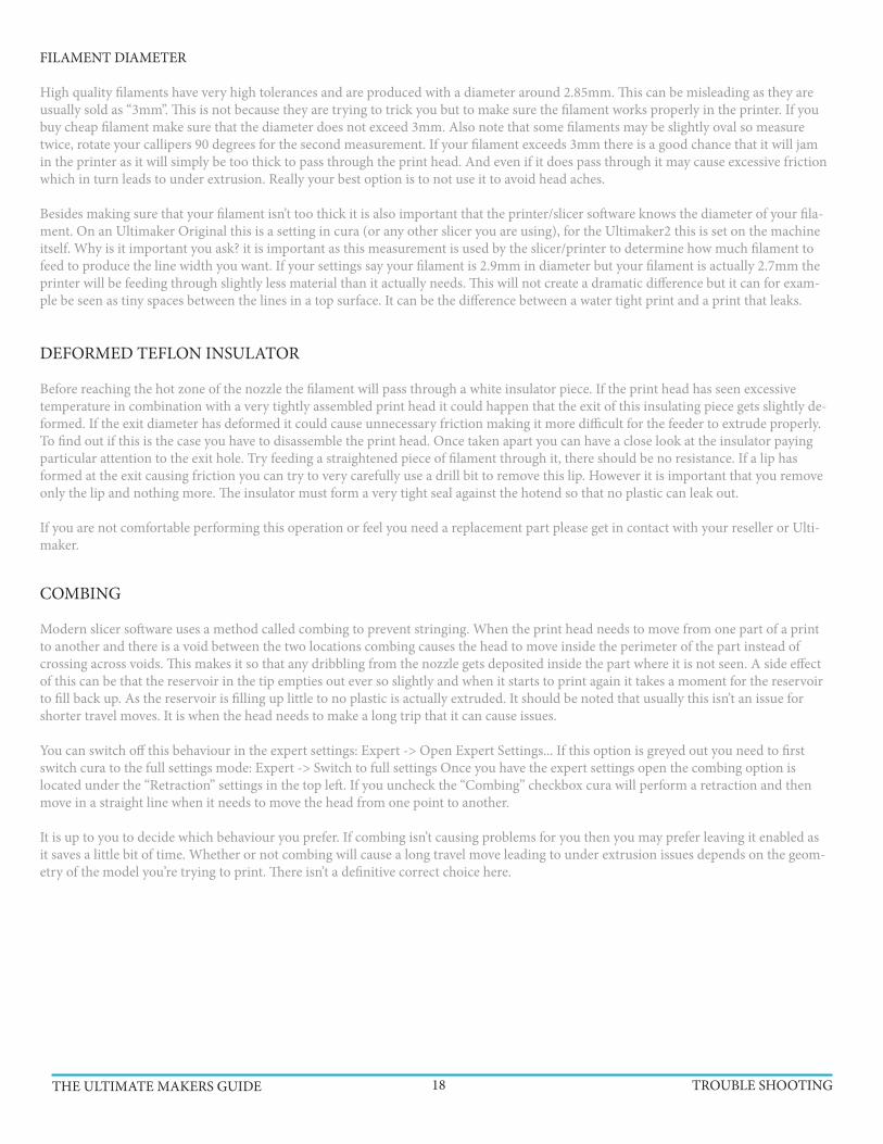
FILAMENT DIAMETER
High quality filaments have very high tolerances and are produced with a diameter around 2.85mm. This can be misleading as they are usually sold as “3mm”. This is not because they are trying to trick you but to make sure the filament works properly in the printer. If you buy cheap filament make sure that the diameter does not exceed 3mm. Also note that some filaments may be slightly oval so measure twice, rotate your callipers 90 degrees for the second measurement. If your filament exceeds 3mm there is a good chance that it will jam in the printer as it will simply be too thick to pass through the print head. And even if it does pass through it may cause excessive friction which in turn leads to under extrusion. Really your best option is to not use it to avoid head aches.
Besides making sure that your filament isn’t too thick it is also important that the printer/slicer software knows the diameter of your fila-ment. On an Ultimaker Original this is a setting in cura (or any other slicer you are using), for the Ultimaker2 this is set on the machine itself. Why is it important you ask? it is important as this measurement is used by the slicer/printer to determine how much filament to feed to produce the line width you want. If your settings say your filament is 2.9mm in diameter but your filament is actually 2.7mm the printer will be feeding through slightly less material than it actually needs. This will not create a dramatic difference but it can for exam-ple be seen as tiny spaces between the lines in a top surface. It can be the difference between a water tight print and a print that leaks.
COMBING
Modern slicer software uses a method called combing to prevent stringing. When the print head needs to move from one part of a print to another and there is a void between the two locations combing causes the head to move inside the perimeter of the part instead of crossing across voids. This makes it so that any dribbling from the nozzle gets deposited inside the part where it is not seen. A side effect of this can be that the reservoir in the tip empties out ever so slightly and when it starts to print again it takes a moment for the reservoir to fill back up. As the reservoir is filling up little to no plastic is actually extruded. It should be noted that usually this isn’t an issue for shorter travel moves. It is when the head needs to make a long trip that it can cause issues.
You can switch off this behaviour in the expert settings: Expert -> Open Expert Settings... If this option is greyed out you need to first switch cura to the full settings mode: Expert -> Switch to full settings Once you have the expert settings open the combing option is located under the “Retraction” settings in the top left. If you uncheck the “Combing” checkbox cura will perform a retraction and then move in a straight line when it needs to move the head from one point to another.
It is up to you to decide which behaviour you prefer. If combing isn’t causing problems for you then you may prefer leaving it enabled as it saves a little bit of time. Whether or not combing will cause a long travel move leading to under extrusion issues depends on the geom-etry of the model you’re trying to print. There isn’t a definitive correct choice here.
DEFORMED TEFLON INSULATOR
Before reaching the hot zone of the nozzle the filament will pass through a white insulator piece. If the print head has seen excessive temperature in combination with a very tightly assembled print head it could happen that the exit of this insulating piece gets slightly de-formed. If the exit diameter has deformed it could cause unnecessary friction making it more difficult for the feeder to extrude properly. To find out if this is the case you have to disassemble the print head. Once taken apart you can have a close look at the insulator paying particular attention to the exit hole. Try feeding a straightened piece of filament through it, there should be no resistance. If a lip has formed at the exit causing friction you can try to very carefully use a drill bit to remove this lip. However it is important that you remove only the lip and nothing more. The insulator must form a very tight seal against the hotend so that no plastic can leak out.
If you are not comfortable performing this operation or feel you need a replacement part please get in contact with your reseller or Ulti-maker.
THE ULTIMATE MAKERS GUIDE TROUBLE SHOOTING18

First of all you have to determine if the walls are not touching at all or if they are touching in some parts only. Using a cylinder as an example it is common that there will be two “sides” touching and two that do not.
PARTIALLY TOUCHING
This is very likely caused by the short belts not being tight enough. Please see this section which deals with this issue. Notice how some parts of the infill lines are touching the perimeter lines while others do not. You will usually find that if you imagine drawing a big X over the print you will notice that the bottom left and top right patterns match and similarly the top left and bottom right match
NOT TOUCHING AT ALL
If the walls are not touching each other at all it is an extrusion issue. cura is asking your printer to create a series of 0.4mm lines and is spacing them so that they fuse together. However, if your printer is under extrud-ing slightly the lines will be marginally thinner and they no longer fuse together properly. The solution could be as simple as reducing your print speed slightly or increasing your temperature a few degrees
WALLS NOT TOUCHING - Parts of, or entire walls of the print are not fused and touching.
THE ULTIMATE MAKERS GUIDE TROUBLE SHOOTING19
ANOTHER POSSIBLE CAUSE
There is however something else that might be happening and it is a slicer issue that relates to wall thickness and the size of your noz-zle. We call it the “thin wall problem”. The standard nozzle on an Ultimaker is 0.4mm in diameter so that is the width that cura has to work with to produce your print. Now, say that you have a wall that is 1mm thick, how will cura handle this? It creates two perimeter walls that are 0.4mm each. This leaves a 0.2mm gap between the walls and since the nozzle is twice as big cura cannot fit the nozzle between the walls to fill the void. It should be said that cura is pretty good at dealing with this and will try some tricks to get around this issue but when it fails this void between walls is what you will end up with.
To get around this particular problem you should always try to design thin walls to be multiples of your nozzle size. If that’s not pos-sible you can cheat a bit by changing your nozzle size setting in cura to something slightly smaller and try again. This will cause cura to slightly under extrude to create a thinner line. You can also increase the size to do the opposite. However, it’s very important that you then watch your print speeds as the volume you’re trying to extrude will go up drastically. It is important that you match your wall thickness settings to match your new nozzle setting, you want your wall thickness to be a multiple of your nozzle diameter. If you set your nozzle diameter to 0.3mm you want your wall settings to be 0.3mm, 0.6mm, 0.9mm etc.
It is also worth experimenting with the wall thickness setting and infill percentage. If you’re not getting the result you want with 0.8mm walls you can try 0.4mm or 1.2mm for example. Sometimes having a thinner outer wall helps fill in these thin walls and vice versa. You don’t have to print it out to check, instead use the built in layer view in cura to check your changes. The layer view is found by clicking the big button in the top right of the window.

Excessive bed heat is the culprit in this case. As the plastic is extruded it behaves similarly to a rubber band. Normally this effect is held back by the previous layers in a print. As a fresh line of plastic is laid down it bonds to the previous layer and is held in place until it fully cools down below the glass transition temperature (where the plastic becomes solid). With a very hot bed the plastic is held above this temperature and is still malleable. As new layers of plastic is put down on top of this semi solid mass of plastic the shrinking forces causes the object to shrink. This continues until the print reaches a height where the heat from the bed no longer keeps the object above this temperature and each layer becomes solid before the next layer is put down thus keeping everything in place.
For PLA you will want to keep your bed temperature at around 50-60C which is a nice temperature to keep bed adhesion while not being too
As the print head is completing a top layer travel moves can cause ugly lines to appear. This can be caused by a couple of things. Either the head is mak-ing an actual scratch on the surface or you are seeing slight oozing of plastic during the travel move.
You can try to enable the “z-hop” feature in cura which will find in the ex-pert settings under the retraction heading: Expert -> Open expert settings... This feature will make the printer lift the nozzle a tiny amount just before making a travel move and then move back down once it arrives at the destination. In combination with this you can increase the speed at which the printer executes travel moves. You can increase the default 150mm/s to 250mm/s without problems. The faster move will reduce the amount of time the nozzle can ooze out plastic. Also consider lowering your tempera-ture to further reduce oozing.
To reduce oozing even more you can set the Minimum travel distance to 1 and set Minimum extrusion to 0. This will force cura to always retract before performing a travel move. This may add a bit of printing time as a retraction doesn’t happen instantly.
A side effect of the z-hop feature is that it can leave behind a tiny little blob. However, a small blob is far less visible and easier to remove than a scratch.
LOWER WALL CAVE IN - The lowest parts of the print appear to shrink before reaching the proper dimensions
SCRATCHED TOP SURFACE - The nozzle moves across the top surface and causes what looks like scratches.
THE ULTIMATE MAKERS GUIDE TROUBLE SHOOTING20
hot. By default the bed temperature is set to 75C which is definitely too much for PLA. There is an exception to this however. If you’re printing objects with a very large foot print taking up most of the bed it might be necessary to use a higher bed temperature to make sure the corners do not lift.
In addition to lowering your bed temperature you want your fans to come on early to help cool down the layers as fast as possible. You can change this in the expert settings of cura: Expert -> Open Expert Settings... In the window that opens you will find a section dedi-cated to cooling. Try setting Fan full on at height to 1mm so that the fans come on nice and early.
If you are printing a very small part these steps might not be enough. The layers might simply not have enough time to cool properly before the next layer is put down. To help with this you can print two copies of your object at once so that the print head will alternate between the two copies giving each more time to cool.
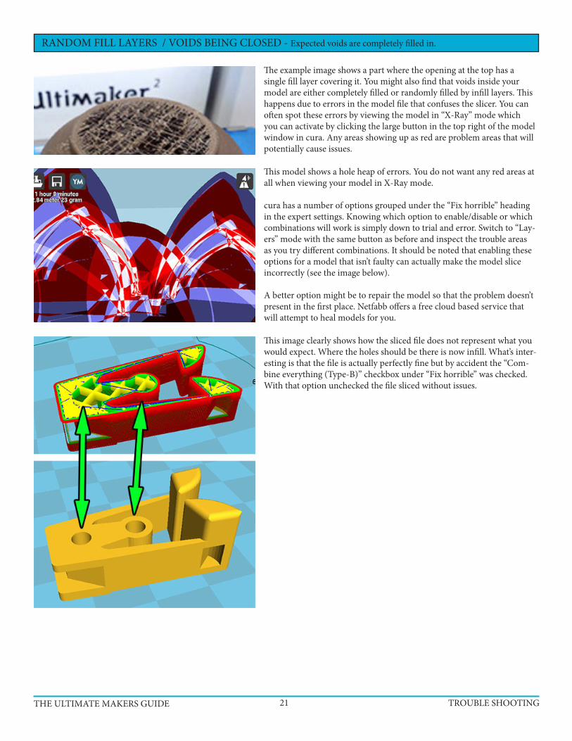
The example image shows a part where the opening at the top has a single fill layer covering it. You might also find that voids inside your model are either completely filled or randomly filled by infill layers. This happens due to errors in the model file that confuses the slicer. You can often spot these errors by viewing the model in “X-Ray” mode which you can activate by clicking the large button in the top right of the model window in cura. Any areas showing up as red are problem areas that will potentially cause issues.
This model shows a hole heap of errors. You do not want any red areas at all when viewing your model in X-Ray mode.
cura has a number of options grouped under the “Fix horrible” heading in the expert settings. Knowing which option to enable/disable or which combinations will work is simply down to trial and error. Switch to “Lay-ers” mode with the same button as before and inspect the trouble areas as you try different combinations. It should be noted that enabling these options for a model that isn’t faulty can actually make the model slice incorrectly (see the image below).
A better option might be to repair the model so that the problem doesn’t present in the first place. Netfabb offers a free cloud based service that will attempt to heal models for you.
RANDOM FILL LAYERS / VOIDS BEING CLOSED - Expected voids are completely filled in.
THE ULTIMATE MAKERS GUIDE TROUBLE SHOOTING21
This image clearly shows how the sliced file does not represent what you would expect. Where the holes should be there is now infill. What’s inter-esting is that the file is actually perfectly fine but by accident the “Com-bine everything (Type-B)” checkbox under “Fix horrible” was checked. With that option unchecked the file sliced without issues.
INSIDER TIPS + TRICKS
THE ULTIMATE MAKERS GUIDE TIPS + TRICKS22
GLUE - USE IT SPARINGLY, IF AT ALL.
The Ultimaker manual recommends applying a thin layer of glue to the buildplate before starting a print. And yes, glue can help your print stick to the buildplate better, and it can be used to compensate for minor buildplate leveling issues that can’t be corrected in any other way.
The problem with glue is that it seems to accelerate the rate at which residue accumulates inside of the Ultimaker’s nozzle, leading to more frequent clogs and extrusion issues. It can also cause parts to stick too well, making removal a pain. In most cases, glue is completely unnecessary:
BUILDPLATE LEVELING - THE ‘THIRD’ SCREW
When leveling the buildplate, the wizard will point out the two front screws that you can turn to fine-tune your level. What it won’t tell you is that there’s actually a third screw you can adjust, as well. This screw is located underneath the build plate and towards the back (and in the center).
This screw adjusts the rear-center height, and can be very useful if you’ve just reassembled your printhead and now find that you can’t level things properly because one notch of height adjustment (through the printer’s wizard interface) moves from ‘a bit too low’ to ‘a bit too high’. By turning the third screw, you can dial in the middle ground between ‘a bit too low’ and ‘a bit too high’ and get your buildplate leveled correctly.
Oh, and since it’s not immediately obvious what affect adjusting the screws has, tightening a buildplate screw will lower the glass plate and increase the distance between the nozzle and the glass. Loosening will have the opposite effect.
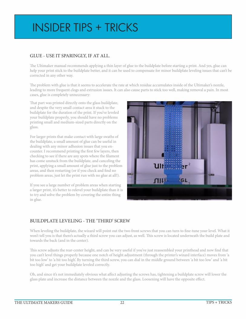
That part was printed directly onto the glass buildplate, and despite the very small contact area it stuck to the buildplate for the duration of the print. If you’ve leveled your buildplate properly, you should have no problems printing small and medium-sized parts directly on the glass.
For larger prints that make contact with large swaths of the buildplate, a small amount of glue can be useful in dealing with any minor adhesion issues that you en-counter. I recommend printing the first few layers, then checking to see if there are any spots where the filament has come unstuck from the buildplate, and canceling the print, applying a small amount of glue just to the problem areas, and then restarting (or if you check and find no problem areas, just let the print run with no glue at all!).
If you see a large number of problem areas when starting a larger print, it’s better to relevel your buildplate than it is to try and solve the problem by covering the entire thing in glue.
THE ULTIMATE MAKERS GUIDE TIPS + TRICKS23
BUILDPLATE LEVELING - THE WIZARD ONLY WORKS ONCE
The wizard that walks you through the buildplate leveling process is helpful; but only until your first successful leveling at-tempt. The problem is that the wizard will tell you to adjust the buildplate screws in order to level it out. But if you’ve already done this (and confirmed the result) then your buildplate is level and playing with the screws will only make it worse!
Once you’ve successfully leveled your buildplate the first time, it’s not going to drift out of level and the only thing you should ever need to adjust again is its offset height relative to the printhead. That’s the first and the fourth step in the leveling wizard and something you’ll want to do if/when you disassemble and reassemble your printhead, as the nozzle height is likely to change slightly when you do so.
So if your buildplate is already level, and you need to adjust the height using the leveling wizard, the only thing you want to worry about is step 1 (or step 4). The other steps you should just click through without touching anything. If you find you need to adjust the third screw in order to dial in the correct height, you should also adjust the other two screws by exactly the same amount to ensure that everything stays nice and level.
And in terms of getting to your first successful level, the wizard’s suggestion of using a piece of paper will get you pretty close. But the best way I’ve found to fine-tune things further is to start printing a large object and adjust the buildplate screws as the first layer is printing.
If you notice that the first layer seems too thin in some areas, then you’ll want to tighten the nearest buildplate screw to lower the glass a bit. And if you notice that parts of the first layer are too thick and/or not sticking to the buildplate, then you should loosen the nearest buildplate screw to raise the glass in that area.
THE NOZZLE - CLEAN IT OFTEN
When printing residue can build up in the nozzle, resulting in underextrusion and clogs if left unchecked. And residue build-up can be difficult or impossible to actually see, as even if the nozzle itself seems clear there can still be enough residue stuck around the sides to cause problems with a print. This can complicate troubleshooting, as a number of other issues can cause the same sort of problems with a print making it all too easy to blame a different component for a problem that’s actually being caused by a dirty nozzle.
So it’s best to take a few minutes to clean out the nozzle every once in awhile. For instance, when changing filaments or when-ever else you decide to remove the filament from the printer. The best way to clean the nozzle is to follow the steps described in the following PDF document:
https://www.ultimaker.com/spree/uploads/113/original/Ultimaker_2_Atomic_Method.pdf
Once you’ve gotten used to it, it should only take a few minutes to step through the cleaning process, and you’ll have ruled out a common but hard-to-spot cause of printing issues.
PRINTING SOUNDS - USE YOUR EARSThe Ultimaker 2 is a very quiet printer when everything is working well. And when it’s not working well, you can usually hear it.
The most common issue is underextrusion during a print, which can usually be heard in the form of loud and distinct ticking sounds from the feeder. An occasional tick isn’t usually a problem, but if you’re getting multiple loud ticks in a row it’s time to intervene if you want you print to succeed.
If you’re fortunate, the cause of the issue will be something simple, like a snag on your filament spool. Usually unspooling a bit of filament to get past the snag will solve this issue. If the ticking has gone on for awhile, however, you may find that you filament has been ground down/deformed a bit (especially if your feeder is tuned too aggressively).
If the deformation isn’t too severe, you may be able to clear the issue by gently pushing the filament through the feeder until the deformed bit is past the feeder wheel (and blowing/brushing off any filament dust that’s accumulated within the feeder). If you’re unable to do that, then you’ll likely have to cancel and restart the print.

MAKER NOTES. .4mm font only. (tee-hee)
THE ULTIMATE MAKERS GUIDE NOTES24

MAKER NOTES.
THE ULTIMATE MAKERS GUIDE NOTES25

MAKER NOTES.
THE ULTIMATE MAKERS GUIDE NOTES26

Still Need More #MAKING?
https://www.facebook.com/TheSlvrLining
http://ultimaker.com/http://3dverkstan.se/
https://plus.google.com/u/0/b/112619083889956289587/112619083889956289587/about/p/pub
https://twitter.com/AdamMahardyhttp://instagram.com/the.makersmovement/
http://themakersmovement.tumblr.com/
http://themakermovements.wordpress.com/
http://en.wikipedia.org/wiki/3D_printing
http://www.shapeways.com/
3dprintingindustry.com/
http://grabcad.com/
3dprinting.com/
www.3ders.org/
http://www.thingiverse.com/


