Thesis Proposal - Pennsylvania State University · Thesis Proposal Brad Oliver - Structural Johns...
17
Johns Hopkins Graduate Student Housing Thesis Proposal 929 North Wolfe Street Baltimore, Maryland Brad Oliver – Structural Advisor: Professor Memari 12/09/2011
Transcript of Thesis Proposal - Pennsylvania State University · Thesis Proposal Brad Oliver - Structural Johns...

Johns Hopkins Graduate Student Housing
Thesis Proposal
929 North Wolfe Street Baltimore, Maryland
Brad Oliver – Structural
Advisor: Professor Memari
12/09/2011
Thesis Proposal
Brad Oliver - Structural Johns Hopkins Grad Student Housing 929 North Wolfe Street
Advisor: Prof. Memari Baltimore, Maryland
12/09/11 P a g e 2
Table of Contents Executive Summary - ..................................................................................................................................... 3
Introduction – ............................................................................................................................................... 4
Structural Systems – ..................................................................................................................................... 6
Foundations: .................................................................................................................................... 6
Floor Framing: .................................................................................................................................. 7
Lateral System: ................................................................................................................................. 9
Problem Statement – .................................................................................................................................. 10
Problem Solution –...................................................................................................................................... 11
Breadth Topics – ......................................................................................................................................... 12
Construction Management: ........................................................................................................... 12
Architecture: .................................................................................................................................. 12
Solution Method – ...................................................................................................................................... 13
Task and Tools – .......................................................................................................................................... 15
Schedule – ................................................................................................................................................... 16
Conclusion – ................................................................................................................................................ 17

Thesis Proposal
Brad Oliver - Structural Johns Hopkins Grad Student Housing 929 North Wolfe Street
Advisor: Prof. Memari Baltimore, Maryland
12/09/11 P a g e 3
Executive Summary -
The goal of this proposal is to identify an area to redesign for the semester as well as to breadth
studies. Previous technical reports showed that the Johns Hopkins Graduate Student Housing
project is a very efficient structure and also code compliant. Due to interests in seismic activity,
a scenario was presented for this proposal that would change the location from Baltimore, to San
Francisco, California.
Before moving the site to San Francisco, a steel system for gravity and lateral loads will be
designed for Baltimore. At the current location, wind loads will most likely be the controlling
case due to the building height (204 feet) and the reduced seismic weight. To resist the lateral
loads, an eccentric braced frame will be utilized due to architectural flexibility. An eccentric
braced frame will allow for the design to work around openings required for doors and elevator
shafts.
Using steel frames in interior and exteriors spaces lead to an architectural breadth. The goal of
the redesign is to minimize cost and structural depth similar just like the original design, while
maintaining a functional and visually appealing architecture. Any columns or braced frames
added will need to be investigated to ensure functionality and pleasing aesthetics. Designing the
structure at the current location first will also allow for a construction management breadth study
incorporating a schedule and cost comparison between concrete and steel. It is expected that the
steel will lead in an expedited schedule saving money during construction, but more expensive
material costs.
Once comparisons are made, the site will be changed to San Francisco due to an interest in
seismic activity. The lateral system will be designed using a dual system of eccentric braced
frames, and moment connections capable of resisting at least 25% of the seismic loads. A dual
system is required because many of the lateral systems, such as the existing shear walls, are
limited to a maximum height of 160 feet in seismic design category D.
The structure will be analyzed once again considering any additional impacts in schedule and
costs. It is expected that costs will increase and create a slightly longer schedule due to larger
member sizes and more complicated connections.

Thesis Proposal
Brad Oliver - Structural Johns Hopkins Grad Student Housing 929 North Wolfe Street
Advisor: Prof. Memari Baltimore, Maryland
12/09/11 P a g e 4
Introduction –
Located just outside the heart of Baltimore, 2 blocks from Johns Hopkins campus, is the site for
the new John Hopkins Graduate Student Housing. This housing project is being constructed in
the science and technology park of John Hopkins. A developing “neighborhood”, the science
and technology park is over 277,000 sq. ft. which is planned to host at least five more buildings
dedicated to research for John Hopkins University. The site is also directly across from a 3 acre
green space. This location is ideal because
it places graduate students within walking
distance of the schools hospitals, shopping,
dining and relaxing.
John Hopkins Graduate Student Housing
project is a new building constructed with
brick and glass facades for a modern look.
Upon completion, the building’s main
function is predominantly for graduate residential use, providing 929 bedrooms over 20 floors.
There are efficiencies, 1, 2, and 4 bedroom apartments available. Other features include a fitness
room and rooftop terrace. A secondary function of the building is three separate commercial
spaces located on the first floor. Retail spaces provide a mixed use floor, creating a welcoming
environment and bringing in additional revenue. At the 10th
floor, the typical floor size
decreases, creating a low roof and a tower for the remaining ten floors. Glass curtain walls on
two corners of the building also begin on the 10th
floor and extend to the upper roof.
The façade of John Hopkins GSH is composed mainly of red brick and tempered glass with
metal cladding. Large storefront windows will be located on the first floor and approximately 6’
x 6’ windows in the apartments. The curtain wall is to be constructed of glass and metal
cladding that can withstand wind loads without damage. There is a mechanical shading system
in the windows to assist in the LEED silver certification.
Figure 1 - Showing glass and brick facade along with curtain
wall.

Thesis Proposal
Brad Oliver - Structural Johns Hopkins Grad Student Housing 929 North Wolfe Street
Advisor: Prof. Memari Baltimore, Maryland
12/09/11 P a g e 5
John Hopkins GSH is striving to achieve
LEED silver certification. Most of the points
accumulated to achieve this level come from
the sustainable sites category. A total of 20/26
points were picked up in this category due to a
number of achievements such as; community
connectivity, public transportation access, and
storm water design and quality control. Indoor
air quality is the next largest category where
the building picks up an additional 11 points
for the use of low emitting materials throughout
construction. Several miscellaneous points are
picked up for using local materials and recycling efforts as well. Shading mechanisms are also
implemented throughout the design as well as an accessible green roof.
There are three different types of roofs on this project. Above the concrete slab on the green roof
is a hot rubberized waterproofing followed by polystyrene insulation, a composite sheet drying
system, and finally the shrubbery. The sections of roof containing pavers will be constructed
using the same waterproofing, a separation sheet, the insulation and finally pavers placed on a
shim system. The remaining portions of the roof will be constructed using a TPO membrane
system.
Figure 2 - an overhead showing the green roof and large
green area across the street. Courtesy of Marks-Thomas
Architects.

Thesis Proposal
Brad Oliver - Structural Johns Hopkins Grad Student Housing 929 North Wolfe Street
Advisor: Prof. Memari Baltimore, Maryland
12/09/11 P a g e 6
Structural Systems –
Foundations:
A geotechnical report was created based on 7 soil test borings drilled from 80’ to 115’ deep.
Four soil types were found during these tests: man placed fill from previous construction 7-13
feet deep, Potomac group deposits of silty sands at 40-75 feet, and competent bedrock at 80-105
feet. Soil tests showed a maximum unconfined compressive strength of 12.37 ksi. The expected
compression loads from the structure were 2400k and 1100k for the 20 and 9 floor towers,
respectively. The foundation system will also have to support an expected uplift and shear force,
respectively, of 1400k per column and 180k per column. Based on pre-existing soils and heavy
axial loads it was determined that a shallow foundation system was neither suitable nor
economical.
In order to reach the competent bedrock, John Hopkins GSH sits on deep caissons 71-91 feet
deep. Caissons range in 36-54” in diameter and are composed of 4000psi concrete. Grade
beams, 4000psi, sit on top of the
caissons followed by the slab on
grade. Slab on grade consists of
3500 psi reinforced with
W2.9XW2.9 and rests on 6” of
granular fill compacted to at least
95% of maximum dry density based
on standard proctor.
According to the geotechnical
report, the water table is
approximately 10 feet below the
first floor elevation, therefore a sub
drainage system was not necessary.
Figure 3 - a detail section of a caisson and column. Courtesy of EDR.

Thesis Proposal
Brad Oliver - Structural Johns Hopkins Grad Student Housing 929 North Wolfe Street
Advisor: Prof. Memari Baltimore, Maryland
12/09/11 P a g e 7
Floor Framing:
Dead and live loads are supported in John Hopkins GSH through a 2-way post-tensioned slab.
The slab is typically 8” thick normal weight 5000 psi concrete reinforced with #4 bars at 24” on
center along the bottom in both directions. The tendons are low-relaxation composed of a 7-wire
strand according to ASTM A-416. Effective post tensioning forces vary throughout the floor,
but the interior bands are typically 240k and 260k. This system is typical for every floor except
for the 9th
which supports a green roof and accessible terrace. Higher loads on this floor require
a 10” thick 2 way post tensioned slab reaching a maximum effective strength of 415k. The
bottom layer of reinforcing in this area is also increased to #5 bars spaced every 18”. One bay on
the 9th
floor (grid lines 7-8) is constructed with a 10” cast in place slab. Plans of this floor can be
found in appendix E.
Mechanical penthouses exist on the 9th
and 20th
roof constructed with a steel moment frame.
Typical sizes for the 9th
floor penthouse are W10’s and W12’s with 1.5” 20 gage “B” metal deck.
As for the 20th
floor penthouse, the typical beam size is W16x26. Equipment will be supported
on concrete pads typically 4” thick. Two air handling units and cooling towers on the roof will
require 6” pads.
Figure 4 - Typical floor plan of upper tower. Courtesy of EDR.
Thesis Proposal
Brad Oliver - Structural Johns Hopkins Grad Student Housing 929 North Wolfe Street
Advisor: Prof. Memari Baltimore, Maryland
12/09/11 P a g e 8
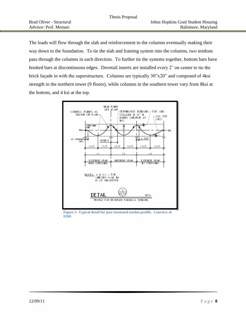
The loads will flow through the slab and reinforcement to the columns eventually making their
way down to the foundation. To tie the slab and framing system into the columns, two tendons
pass through the columns in each direction. To further tie the systems together, bottom bars have
hooked bars at discontinuous edges. Dovetail inserts are installed every 2’ on center to tie the
brick façade in with the superstructure. Columns are typically 30”x20” and composed of 4ksi
strength in the northern tower (9 floors), while columns in the southern tower vary from 8ksi at
the bottom, and 4 ksi at the top.
Figure 5- Typical detail for post tensioned tendon profile. Courtesy of
EDR.

Thesis Proposal
Brad Oliver - Structural Johns Hopkins Grad Student Housing 929 North Wolfe Street
Advisor: Prof. Memari Baltimore, Maryland
12/09/11 P a g e 9
Figure 6 - detail tying shear wall into foundation.
Courtesy of EDR.
Lateral System:
John Hopkins GSH is supported laterally through a cast in place reinforced concrete shear wall
system. All of the shear walls are 12” thick and located throughout the building and around
stairwells and elevator shafts. Shear walls in the 9 floor tower are poured with 4000psi strength
concrete while shear walls in the 20 floor tower vary in three locations. From the foundation to
7th
floor, 8ksi concrete is used, 6ksi from 7th
to below 14th
floor, and 4ksi for walls above the 14th
floor. The shear walls are tied into the foundation
system through bent vertical bars 1’ deep into the
grade beam as shown in figure 6. Shear walls are
shown below in the figure with N-S walls highlighted
in blue and E-W walls red. Walls in the center of the
building will support lateral stresses directly, while
those on the end support the torsion effects caused by
eccentric loads.
Figure 7 - Shear wall layout. Courtesy of EDR.

Thesis Proposal
Brad Oliver - Structural Johns Hopkins Grad Student Housing 929 North Wolfe Street
Advisor: Prof. Memari Baltimore, Maryland
12/09/11 P a g e 10
Problem Statement –
After performing a gravity and lateral analysis, the Johns Hopkins Graduate Student Housing
project was found to be efficient and sufficient. In order to create problems in the structure and
provide a learned experience in seismic area, a scenario has been proposed where the project site
has been changed from Baltimore to San Francisco, California. The site change results in the
structure being classified in seismic design category D.
Once the building location has been changed, the first problem occurs in the lateral system.
ASCE 7-05 does not permit ordinary reinforced shear walls in SDC D; therefore, a dual system
with moment frames capable of resisting at least 25% of the seismic loads will need to be
designed. Lateral loads will be resisted primarily through eccentrically braced frames which
need to be designed.
To reduce the seismic weight and loads on the building, the post-tensioned floor system will also
need to be redesigned using a composite floor system. Using a steel frame will also provide
more ductility to the structure as well.
The original design goals such as cost, minimal floor-floor depth, and appealing architecture,
must also be of importance for the redesign. The project was found to be torsionally sensitive in
Tech Report 3, so an additional goal for this redesign is to minimize torsional effects.

Thesis Proposal
Brad Oliver - Structural Johns Hopkins Grad Student Housing 929 North Wolfe Street
Advisor: Prof. Memari Baltimore, Maryland
12/09/11 P a g e 11
Problem Solution –
To solve the problems associated with moving the building to a seismic region, a steel framing
system needs to be designed to withstand the gravity loads as defined by ASCE7-05. The steel
structure will be designed to be as economical as possible while keeping the floor-to-floor
heights at a minimum just like Tech Report 2. To minimize the structural depth, a composite
system will be used to take advantage of concrete’s strong compression properties. IBC 2006
mandates a 2-hour fire rating; therefore, the deck will also need to be designed accordingly. The
gravity system also needs to satisfy strength and serviceability requirements such as L/240 for
total load and L/360 for live load.
Once the gravity system has been designed, a lateral system needs to designed to resist wind and
seismic loads. Eccentrically braced frames will be the main lateral force resisting system. In
order to reduce the torsional sensitivity of the building, braced and moment frames will be placed
near the core of the building as well as the exterior. The frames also need to satisfy strength and
serviceability requirements. To maximize the ductility in the system and the architectural
flexibility, an eccentric braced frame, and moment frames will be designed. For eccentric frames
the link element, the beam between braces, is the critical element because it will deform the
most. Deformation will provide ductility for the system and absorb seismic loads and reduce the
chances of a sudden failure. The lateral system will need to comply with ASCE standards
regarding drift limits according to table 12.12-1.

Thesis Proposal
Brad Oliver - Structural Johns Hopkins Grad Student Housing 929 North Wolfe Street
Advisor: Prof. Memari Baltimore, Maryland
12/09/11 P a g e 12
Breadth Topics –
Construction Management:
Changing the main construction method will significantly impact the schedule and cost. Steel
erection typically results in quicker schedule than concrete because there is no need for
formwork construction and tear down which would save the owner money. A expedited
schedule would result in some cost savings; however, steel is typically more expensive than
concrete. Steel connections are also an increased expense, and if the building height isn’t kept to
a minimum, the façade will cost more money as well.
Comparisons will be made with regards to cost and schedule analysis at the current location
between concrete and steel, and then again once the site is moved to a seismic region. The
seismic region will result in more detailed connections, larger members, and possibly more
members.
Architecture:
Altering the lateral system from shear walls to a steel braced frame will change numerous
architectural features. With regards to the interior, small openings such as doors, mechanical
equipment, and elevator shafts will need to be inspected to ensure they can maintain their
function. Eccentric braced frames were chosen so that they can be arranged to avoid major
conflicts.
Once the project site has been moved to a seismic location, torsion is undesirable; therefore,
braced frames may need to be added in additional locations and possibly along the exterior. The
modern façade appearance is an important aspect to the design so care must be taken to ensure
the braced frames do not intrude on the architecture. Columns may also need to be added to
ensure the building can be constructed without shoring. Areas of concern are where shear walls
are currently located without columns; therefore, those areas need to be inspected as well.
Thesis Proposal
Brad Oliver - Structural Johns Hopkins Grad Student Housing 929 North Wolfe Street
Advisor: Prof. Memari Baltimore, Maryland
12/09/11 P a g e 13
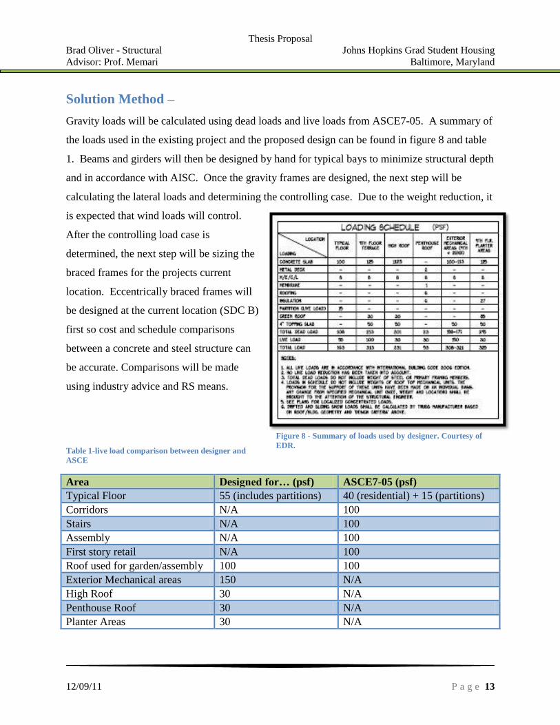
Figure 8 - Summary of loads used by designer. Courtesy of
EDR.
Solution Method –
Gravity loads will be calculated using dead loads and live loads from ASCE7-05. A summary of
the loads used in the existing project and the proposed design can be found in figure 8 and table
1. Beams and girders will then be designed by hand for typical bays to minimize structural depth
and in accordance with AISC. Once the gravity frames are designed, the next step will be
calculating the lateral loads and determining the controlling case. Due to the weight reduction, it
is expected that wind loads will control.
After the controlling load case is
determined, the next step will be sizing the
braced frames for the projects current
location. Eccentrically braced frames will
be designed at the current location (SDC B)
first so cost and schedule comparisons
between a concrete and steel structure can
be accurate. Comparisons will be made
using industry advice and RS means.
Table 1-live load comparison between designer and
ASCE
Area Designed for… (psf) ASCE7-05 (psf)
Typical Floor 55 (includes partitions) 40 (residential) + 15 (partitions)
Corridors N/A 100
Stairs N/A 100
Assembly N/A 100
First story retail N/A 100
Roof used for garden/assembly 100 100
Exterior Mechanical areas 150 N/A
High Roof 30 N/A
Penthouse Roof 30 N/A
Planter Areas 30 N/A

Thesis Proposal
Brad Oliver - Structural Johns Hopkins Grad Student Housing 929 North Wolfe Street
Advisor: Prof. Memari Baltimore, Maryland
12/09/11 P a g e 14
After the initial analysis and comparisons between steel and concrete at the current location, the
project site will be moved to San Francisco (SDC D). More stringent seismic criteria in this
location require that the lateral system be a dual system with at the moment frames being capable
of resisting 25% of the seismic loads. This dual system is required due to height limitations on
shear walls and eccentrically braced frames according to ASCE7-05 chapter 12.
The preliminary design of eccentric frames will be through AE 538 notes and the AISC manual.
Once preliminary designs are done, an ETABS model will be created similar to Tech Report 3 to
check the lateral displacements. As stated earlier, story drifts must be limited to those prescribed
by chapter 12 of ASCE 7-05. Member forces will be checked to ensure sufficient strength. If
anything is not compliant or the building is still torsionally sensitive, the braced frames will be
redesigned or the positioning of the frames will be re-evaluated.
Once the design has been completed in San Francisco, a comparison will once again be made
between the two steel structures to determine how much more it would cost the owner to move
the building from Baltimore to San Francisco.

Thesis Proposal
Brad Oliver - Structural Johns Hopkins Grad Student Housing 929 North Wolfe Street
Advisor: Prof. Memari Baltimore, Maryland
12/09/11 P a g e 15
Task and Tools –
Task 1: Design steel gravity system
Determine slab/ deck size based on Vulcraft design guides
Determine preliminary members using AISC while complying with strength
and serviceability requirements and minimizing structural depth
Add Columns as necessary to allow un-shored construction
Task 2: Design steel eccentrically braced frames for current location SDC B
Identify controlling lateral loads. Wind loads will be based on ASCE7-05
criteria for wind, and seismic loads determined from building weight and
equivalent lateral force method.
Determine layout of frames to minimize torsional and architectural impacts.
Create a model in ETABS to ensure frames are adequate
Check member forces and relative stiffness values by hand.
Task 3: Prepare cost and schedule analysis between steel and concrete structure.
Need to obtain a current schedule and cost information from the construction
manager.
Create adjusted schedule and run cost comparisons using industry
recommendations, RS Means, and Microsoft Project.
Compare the two systems.
Task 4: Design dual system to resist lateral forces
Change to project site to a new location (SDC D).
Research types of connections necessary and construction difficulty.
Design eccentrically braced and moment frames based on new lateral loads.
Create ETABS model to ensure code drift limitations are met.
Check member forces and relative stiffness values by hand.
Task 5: Compare the changes between systems in SDC B and SDC D.
Compare member sizes, cost, and possible increase in schedule due to more
complicated member connections.
Task 6 (ongoing): Architectural Breadth
Analyze exiting architecture and locate openings in lateral system.
Ensure braced frames are not impacting functional spaces.
Confirm additional columns are not impacting functional spaces.
Check that braced frames are not impacting the façade appearance.
Task 7: Final Presentation

Thesis Proposal
Brad Oliver - Structural Johns Hopkins Grad Student Housing 929 North Wolfe Street
Advisor: Prof. Memari Baltimore, Maryland
12/09/11 P a g e 16
Schedule –

Thesis Proposal
Brad Oliver - Structural Johns Hopkins Grad Student Housing 929 North Wolfe Street
Advisor: Prof. Memari Baltimore, Maryland
12/09/11 P a g e 17
Conclusion –
Johns Hopkins Graduate Student Housing will be redesigned using a steel structure at the current
location. A redesign will attempt to minimize structural depth, cost, and architectural impacts.
Once the gravity system has been designed, a lateral system of eccentrically braced frames will
be devised to resist the controlling loads, most likely wind. Eccentrically braced frames will be
the primary resisting system due to the architectural flexibility.
During design, architectural features affected will be investigated and solutions will be
implemented along the way. Once the design in Baltimore has been completed, a construction
management breadth will be completed to compare the steel structure to concrete. A steel
structure will most likely result in a faster schedule, but also more expensive material and façade
costs.
Once accurate comparisons are made, the site will be moved to San Francisco, California
changing the seismic design category from B to D. To compensate for this change, a dual
system utilizing moment frames and an eccentrically braced frame will be designed. As in the
previous location, frames will be placed to minimize torsion and architectural impacts.
After completing the steel structure in a new location, comparisons will be made once again.
Cost comparisons will determine how much more expensive it is to alter the steel structure to be
resist loads in a high seismic area.