The!se˙f Vacuum Interruption at Transmission Voltages · the same companies were developing SF6 CB...
33
VIL 2006 All Rights Reserved 1 IEEE Switchgear Committee Spring 2008 The Use of Vacuum Interruption at Transmission Voltages Dr Leslie T Falkingham Managing Director Vacuum Interrupters Limited [email protected]
Transcript of The!se˙f Vacuum Interruption at Transmission Voltages · the same companies were developing SF6 CB...

VIL 2006 All Rights Reserved 1
IEEE Switchgear Committee Spring 2008
The Use of Vacuum Interruption at Transmission
Voltages
Dr Leslie T Falkingham
Managing Director
Vacuum Interrupters Limited

VIL 2006 All Rights Reserved
IEEE Switchgear Committee
Spring 2008 2
History: Origins
Serious development of Power Vacuum Interrupters started both in England and in the USA in the 1950�s.
One of the first applications was for transmission circuit breakers!
The photo shows an AEI 132 kV vacuum circuit breaker in service with the CEGB at West Ham (London) in 1967. It and a number of others remained in service into the late 1990�s.

VIL 2006 All Rights Reserved
IEEE Switchgear Committee
Spring 2008 3
Introduction
The Presentation covers the following topics:
1. A short history
2. What was the problem with the 1960�s technology?
3. Vacuum interrupter & switchgear technology
4. Difficulties facing vacuum interruption at higher voltages
5. Today and the (near) future

VIL 2006 All Rights Reserved
IEEE Switchgear Committee
Spring 2008 4
Introduction: Why Vacuum?
Vacuum has unique advantages in switching electrical circuits (CalTech: Sorenson & Mendelhall 1920�s)
1. Dielectric strength @ 40kV/mm, (125kV/1/8 inch)
2. Natural interruption capability @ 4kA
3. Rated enhanced interruption capability >100kA
4. Almost no wear (>100 full short circuit interruptions) (>50,000 load current interruptions)
5. Current chopping can be tuned by design as low as 0.4A
6. Low energy for operation (Joules not kJoules)
7. Sealed for life/ laboratory manufacture/quality assured

VIL 2006 All Rights Reserved
IEEE Switchgear Committee
Spring 2008 5
Result of a collaboration between the CEGB and GEC/AEI
Intended to be a technology tester
Six units entered service in 1967/68 for evaluation on the system
History - The VGL8 132kV Vacuum Circuit Breaker

VIL 2006 All Rights Reserved
IEEE Switchgear Committee
Spring 2008 6
History - The VGL8 132kV Vacuum Circuit Breaker
The VCB was a �T� configuration with four VI in each arm, giving 8 VI in series per phase!
Voltage sharing was performed by parallel capacitors and a complex mechanism provided the required movement
Each �arm� was covered in a porcelain insulator and pressurised to 20psi with SF6

VIL 2006 All Rights Reserved
IEEE Switchgear Committee
Spring 2008 7
History - The VGL8 132kV Vacuum Circuit Breaker
Service History
The VCB�s in service in London operated for 30 years without problem and were removed at the end of the 1990�s when no longer needed.
The VCB�s in service at Tir John (Wales) operated without problem until 1980 when, after a circuit reconfiguration, they were relocated to Devon
Then during the 1980�s in the new location a problem was seen.

VIL 2006 All Rights Reserved
IEEE Switchgear Committee
Spring 2008 8
History - The VGL8 132kV Vacuum Circuit Breaker
Service History
The new location included large capacitors, and a complex split busbar arrangement at the local power station.
A number of large (3.5pu) overvoltages were seen on the system, causing flashovers on transformer bushings.
Computer studies and system monitoring including switching operations were carried out but failed to reproduce the effect.
It was assumed in the absence of any other suspects that the VCB were probably to blame.

VIL 2006 All Rights Reserved
IEEE Switchgear Committee
Spring 2008 9
History - The VGL8 132kV Vacuum Circuit Breaker
Service History
Before any action could be taken another high voltage event took place, and the monitoring identified the source as the switching of a HV Bulk Oil circuit breaker.
Surge suppression was fitted to the 132kV transformer bushings and there were no further reported problems.
VIL 2006 All Rights Reserved
IEEE Switchgear Committee
Spring 2008 10
History - The 1960�s problem
At the same time as the development of the VHV VCB the same companies were developing SF6 CB as replacements for the air and oil breakers then in service. Due to the following factors the SF6 was seen as a simpler and much lower cost option:
The VCB needed 8 VI in series per phase which necessitated a very complex mechanical linkage to operate 24 contacts simultaneously.
The use of an existing Oil CB mechanism which was far too strong gave a very high cost for the equipment and maintenance.
VIL 2006 All Rights Reserved
IEEE Switchgear Committee
Spring 2008 11
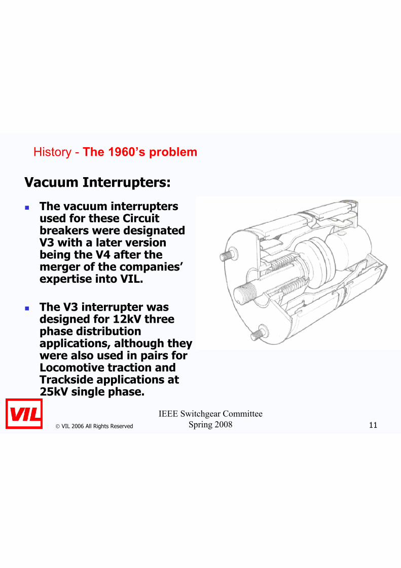
History - The 1960�s problem
Vacuum Interrupters:
The vacuum interrupters used for these Circuit breakers were designated V3 with a later version being the V4 after the merger of the companies�expertise into VIL.
The V3 interrupter was designed for 12kV three phase distribution applications, although they were also used in pairs for Locomotive traction and Trackside applications at 25kV single phase.

VIL 2006 All Rights Reserved
IEEE Switchgear Committee
Spring 2008 12
History - The 1960�s problem
Mechanism:
The stroke of the interrupters was set at 7/8� (22.2mm) plus an overtravel of 3/8� (9.5mm) for contact spring compression. The operating characteristics recommended by the newly formed VIL -who supplied the vacuum interrupters, were:
Average Closing Speed 2-3 ft/second (0.6 � 0.9ms-1)
Average Opening Speed 5-6ft/second (1.5 � 1.8ms-1)
The designers calculated that the mechanism had a moving weight of over 500 lbs (227kg) and that the total energy requirements were 17600 lbs (78kN). Actually the combined moving mass of the contacts was less than 25lb (11.4kg), which is less than 5% of the total moving mass!

VIL 2006 All Rights Reserved
IEEE Switchgear Committee
Spring 2008 13
What was the problem in the 1960s?
In the early days of Vacuum single interrupters could only interrupt voltages up to 17.5 or 24kV.
As a result a large number of interrupters in series were needed to achieve the voltage rating.
In turn this resulted in complex and expensive operating mechanisms
The interrupters used were optimised for the Distribution market where large sales volumes were possible. It was not economically justifiable to develop special interrupters for the relatively small Transmission Switchgear market

VIL 2006 All Rights Reserved
IEEE Switchgear Committee
Spring 2008 14
Vacuum Interrupter Technology
The Manufacture
of vacuum interrupters is performed in special facilities using state of the art technology such as clean rooms and high vacuum furnaces.
Main horizontal laminar flow clean room at VIL,
Finchley, 1978.

VIL 2006 All Rights Reserved
IEEE Switchgear Committee
Spring 2008 15
Manufacturing -One Shot Seal Off
Vacuum interrupter manufacture is a Hi-Tech industrial process.
After assembly interrupters are loaded into a vacuum furnace and brazed and sealed at the same time.
Manufacture of Vacuum Interrupters in South Africa
c1990

VIL 2006 All Rights Reserved
IEEE Switchgear Committee
Spring 2008 16
Vacuum Interrupter Technology
There are four key areas of technology in the design of Vacuum Interrupters:
1. Overall Vacuum Design.
2. Electrical Design
3. Arc Control System
4. Contact Materials.

VIL 2006 All Rights Reserved
IEEE Switchgear Committee
Spring 2008 17
Vacuum Interrupter Technology
There are four key areas of technology in the design of Vacuum Circuit Breakers:
1. Overall Design.
2. Electrical/magnetic Design � close phase centrescan cause magnetic interference between interrupters
3. Mechanism � short stroke & low energy, for example at 38kV, ½� stroke and 150 Joules.
4. Weld Breaking

VIL 2006 All Rights Reserved
IEEE Switchgear Committee
Spring 2008 18
Classic Vacuum Interrupter Design
The photo shows a 15kV V8 interrupter (4 ½� dia.) from the early 1970�s.
This shows the basic design and maincomponentsof a Vacuum Interrupter.
V8 1213, VIL Finchley 1970�s.

VIL 2006 All Rights Reserved
IEEE Switchgear Committee
Spring 2008 19
Arc Control: Radial Magnetic Field (RMF) Contact Geometry
This works by using a self induced Radial Magnetic Field to make the arc move over the contact surface, reducing local heating.
The contact material must allow the arc to move freely over the surface.
Interruption up to 63kA rating is available
Still from HS film @ 5,000 pps showing 2�
diameter RMF contact interrupting 31.5kArms
@12kVrms.

VIL 2006 All Rights Reserved
IEEE Switchgear Committee
Spring 2008 20
Arc Control: Axial Magnetic Field (AMF) Geometry
This works by using a self induced magnetic field in the axis of the arc which prevents the arc from constricting andreduces local heating by spreading the energy over the surface.
The contact material does not have to allow the arc to move freely.
Interruption in excess of 100kA has been achieved commercially.
Still from HS film @ 9,000pps showing an AMF
contact interrupting 40kArms @12kVrms.

VIL 2006 All Rights Reserved
IEEE Switchgear Committee
Spring 2008 21
The Vacuum Arc � Contact Material
The term Vacuum Arc is a misnoma. What we have is really a metal vapour arc in vacuum.
The metal composing the arc gives the arc many of its properties.
Changing the material of the contact can fundamentally change the properties of the arc.
Still from HS film @ 5,000 pps showing 35mm
diameter RMF contact interrupting 20kArms @
12kVrms.

VIL 2006 All Rights Reserved
IEEE Switchgear Committee
Spring 2008 22
Desirable Material Properties
Voltage Application Key Features
1.2-15kV Contactor Low Current Chopping (<0.5A)
High Electrical Life (>3,000,000)
Anti Weld (low strength mechanism)
15-40.5kV C/B High Dielectric Strength (<200kV in 12mm)
High Breaking Capacity (<100kArms)
High Making Capacity (<250kApk)
Anti-Weld (medium strength mechanism)
132kV+ C/B Very High Dielectric Strength (<800kV in50mm?)
High Breaking Capacity (<63kArms)
High Making Capacity (<160kApk)
Anti-Weld (medium strength mechanism)

VIL 2006 All Rights Reserved
IEEE Switchgear Committee
Spring 2008 23
Contact Material
Photomicrograph of
Chromium Copper (CrCu) contact material which was originally developed and patented by English Electric in the 1960�s.
This is now the most popular material for MV Vacuum Interrupters in manufacture today.

VIL 2006 All Rights Reserved
IEEE Switchgear Committee
Spring 2008 24
Mechanisms
Vacuum Interrupters do not need very high energies for operation � the mechanism energy plays no part in the interruption process, it merely moves the contacts apart.
A typical 38kV recloser will use only 150 � 200 Joules of energy to operate as opposed to the 18,000 -24,000 Joules typically needed for a 400kV SF6 Puffer circuit breaker!
This has allowed the use of a very special very low energy technology � The Permanent Magnet Magnetic Actuator.
VIL 2006 All Rights Reserved
IEEE Switchgear Committee
Spring 2008 25
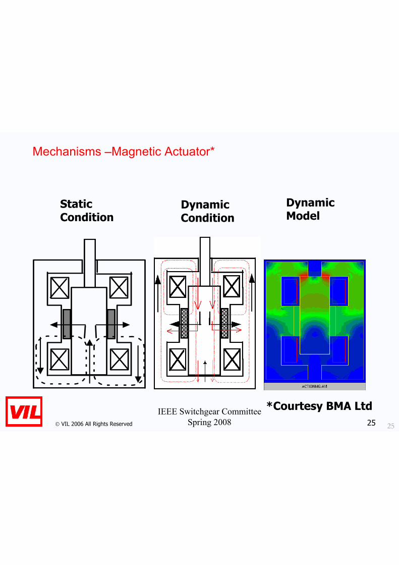
Mechanisms �Magnetic Actuator*
Dynamic Model
Static Condition
Dynamic Condition

VIL 2006 All Rights Reserved
IEEE Switchgear Committee
Spring 2008 26
What is the Situation Today?
Advances in interrupter design over the past forty years mean that single interrupters for 38kV, and 72/84kV are now common.
Higher ratings are now becoming available with single interrupters rated at up to 145kV.
This increase in voltage rating together with the low operating energy requirement allows simple, reliable low cost mechanisms to be used.

VIL 2006 All Rights Reserved
IEEE Switchgear Committee
Spring 2008 27
What is the Situation Today?
The interrupter on the left is rated for 95kV bil, the interrupter on the right for 250kV bil. The length of the interrupters is the same.
This huge increase was achieved by modifying the electrical surfaces of the shields and contacts.

VIL 2006 All Rights Reserved
IEEE Switchgear Committee
Spring 2008 28
Difficulties Facing Vacuum Interruption at Higher Voltages
Physically large interrupters are heavy and generally use more components, this in turn affects the Plant�s capability to manufacture and handle such large devices.
Large devices tend to have many more components and vacuum seals than is normal today leading to manufacturing and quality control difficulties.
A long (larger than 24mm) contact gap affects the capability of the RMF and AMF arc control systems and may reduce interruption capability.
Current Contact Materials are optimised for the MV ratings. It may be necessary to develop new materials which are more suited to these large contact gaps.
X-ray emission at system voltages becomes possible and needs to be taken into consideration.

VIL 2006 All Rights Reserved
IEEE Switchgear Committee
Spring 2008 29
Difficulties Facing Vacuum Interruption at Higher Voltages
A few facts should be mentioned:
At all voltages X-ray emission is zero when the interrupter is in the closed position.
At MV voltages (up to 38kVrms) X-ray emission is zero or negligible.
Generally for MV circuit breakers significant X-rays could only be generated at test voltages.
However once the system voltage gets to higher voltages such as 145kV then the possibility of X-ray emission at system volts becomes significant, although not generally a safety issue.
The real issue for designers is that it is possible for the interrupters to irradiate their local surroundings over a long period, and this may have a detrimental effect on polymeric components or electronics mounted in the circuit breaker locally to the interrupters.

VIL 2006 All Rights Reserved
IEEE Switchgear Committee
Spring 2008 30
The situation today.
JAEPS Vacuum Circuit Breaker rated at 145kV (Courtesy JAEPS)

VIL 2006 All Rights Reserved
IEEE Switchgear Committee
Spring 2008 31
Modern Vacuum High Voltage Circuit Breakers
The development of a single 145 kV vacuum interrupter makes the development of a two break per phase 300kV class Vacuum Circuit Breaker quite simple.
Higher voltage Single and Two break circuit breakers will however require more work on the vacuum interrupter design, arc control, and contact materials.

VIL 2006 All Rights Reserved
IEEE Switchgear Committee
Spring 2008 32
Conclusions
Vacuum circuit breakers up to 145kV are already commercially available.
It is possible with existing technology to forsee relatively low risk vacuum circuit breaker development up to 300kV �400kV.
Above 400kV serious technical difficulties will need to be overcome. However there are projects currently in progress to address these difficulties, targeting vacuum circuit breakers rated up to 750kV.
There is no inherent problem with using vacuum interruption for transmission applications. Vacuum circuit breakers have been successfully used at transmission voltages (132kV) for over 30 years.

VIL 2006 All Rights Reserved
IEEE Switchgear Committee
Spring 2008 33
Questions?