Thermowells - Basic Selection Criteria
25
PDHonline Course E255 (2 PDH) Thermowells - Basic Selection Criteria 2012 Instructor: David A. Snyder, PE PDH Online | PDH Center 5272 Meadow Estates Drive Fairfax, VA 22030-6658 Phone & Fax: 703-988-0088 www.PDHonline.org www.PDHcenter.com An Approved Continuing Education Provider
description
selection of thermowells
Transcript of Thermowells - Basic Selection Criteria

PDHonline Course E255 (2 PDH)
Thermowells - Basic Selection Criteria
2012
Instructor: David A. Snyder, PE
PDH Online | PDH Center5272 Meadow Estates Drive
Fairfax, VA 22030-6658Phone & Fax: 703-988-0088
www.PDHonline.orgwww.PDHcenter.com
An Approved Continuing Education Provider
www.PDHcenter.com PDH Course E255 www.PDHonline.org
© David A. Snyder, Thermowells – Basic Selection Criteria Page 2 of 25
Thermowells – Basic Selection Criteria
David A. Snyder, PE
Course Content
Choosing the proper thermowell for a given process connection and temperature sensor or
thermometer may seem like an easy, straightforward task, but there are several pitfalls and
challenges lurking to trap the unwary and uninitiated.
What does a thermowell do, what purpose does it serve? In some applications, thermometers or
temperature sensors (such as RTDs or thermocouples) are installed directly into the process
without any protection at all. Some examples of this are temperature devices installed directly in
HVAC ducts and the thermometer that one puts in a turkey in order to ensure it is cooked
thoroughly. There are also applications in which thermocouples are welded directly to the
exterior of a pipe to sense the temperature of the fluid flowing through the interior of that pipe.
On the other hand, if the measured process is corrosive, poisonous, hot, or pressurized, a
boundary is required between the process and the outside world. A thermowell is a common
way to provide this boundary (see sidebar for discussion of protection tubes). Here are some of
the advantages that a thermowell provides:
1) Protects the temperature sensor or thermometer from
the force of the flowing or agitated fluid. This force
could bend or break off the sensor or thermometer,
depending on the density and velocity of the fluid.
2) Closes off the process (as previously discussed) such
that the temperature sensor or thermometer can be
removed and replaced without shutting down the
process. To state this differently, you can pull out the
temperature sensor or thermometer without getting
sprayed by the process fluid.
The above advantages come with disadvantages, which include:
1) Increased cost to purchase the thermowell.
2) Slower response to temperature changes, compared to a naked sensor, due to the
thermal inertia of the thermowell.
3) A thermowell presents some resistance to flow, due to the cross-sectional area of the
thermowell, but a well-designed installation can minimize this effect.
Protection tubes are
typically made of metal,
high temperature glass,
or ceramic and are used
in low-pressure / high
temperature applications,
such as industrial
furnaces. This type of
protection will not be
discussed further in this
document.

www.PDHcenter.com PDH Course E255 www.PDHonline.org
© David A. Snyder, Thermowells – Basic Selection Criteria Page 3 of 25
The key factors to consider when selecting a thermowell are:
1) Process connection size and type.
2) Process insertion length (U length)
3) Lagging length (T length)
4) Extension length (E length)
5) Sensor length (X length)
6) Interior diameter (bore) for the sensor or thermometer
7) Internal threads for the sensor or thermometer
8) Shape of thermowell (straight, stepped, tapered, built-up)
9) Material of construction
Process Connection Size and Type: The figures below show some typical thermowell process
connection types. Notice that the process insertion length U and the sensor length X start at two
different places (separated by 0.25”) on the right-hand side of the drawings. Examples of
common process connections include 1” NPT threaded, 2” raised-face flange (RFF), 3/4” socket-
weld, et cetera. The process connection size and type are determined by the nozzle on the tank
or vessel or the fitting on the pipe or duct. Figure 1 shows a 1” NPT threaded process
connection, Figure 2 shows a 1” socket-weld process connection, and Figure 3 shows a 1” 150#
raised-face flanged process connection. Other types of process connections that are available
include Weld-In, Van Stone, and Sanitary, which won‟t be discussed further, but the concepts
covered in this document also apply to those types of thermowells.
FIGURE 1 - THREADED, TAPERED
INTERIOR
DIAMETER
(BORE)
INTERNAL
THREADS
HEX FITTING
THREADED PROCESS
CONNECTION
INTERIOR
DIAMETER
(BORE)
0.25"
X = SENSOR LENGTHU = PROCESS INSERTION LENGTH 1.75"
0.25"T + 1.75"
X = SENSOR LENGTHU = PROCESS INSERTION LENGTH
(T = 0)

www.PDHcenter.com PDH Course E255 www.PDHonline.org
© David A. Snyder, Thermowells – Basic Selection Criteria Page 4 of 25
FIGURE 2 - SOCKET-WELD, TAPERED
INTERIOR
DIAMETER
(BORE)
INTERNAL
THREADS
SOCKET-WELD PROCESS
CONNECTION
INTERIOR
DIAMETER
(BORE)
0.25"
X = SENSOR LENGTHU = PROCESS INSERTION LENGTH 1.75"
(T = 0)
CYLINDER
0.25"
X = SENSOR LENGTHU = PROCESS INSERTION LENGTH T + 1.75"
FIGURE 3 - FLANGED, TAPERED
INTERNAL
THREADS
FLANGED PROCESS
CONNECTION
INTERIOR
DIAMETER
(BORE)
0.25"
X = SENSOR LENGTHU = PROCESS INSERTION LENGTH 2.25"
(T = 0)
INTERIOR
DIAMETER
(BORE)
BOLT HOLES
AS REQ'D BY
FLANGE TYPE
CYLINDER
DIAMETER AND
THICKNESS AS REQ'D
BY FLANGE TYPE
0.25"
X = SENSOR LENGTHU = PROCESS INSERTION LENGTH T + 2.25"

www.PDHcenter.com PDH Course E255 www.PDHonline.org
© David A. Snyder, Thermowells – Basic Selection Criteria Page 5 of 25
Process Insertion Length (U Length): This is how far the thermowell sticks in to or penetrates
the process (vessel, tank, pipe, or duct). On a thermowell catalog cut-sheet (Attachments A
through F), this is denoted as the U length. If the process you are measuring happens to be a
liquid, then the process insertion length is the portion of the thermowell that is wetted by the
process. When selecting the thermowell process insertion length, the depth of the thermowell‟s
mechanical connection to the process must also be taken into account. For example, if we are to
install a thermowell into a Schedule 40 12” diameter pipe, we would choose a process insertion
length that will put the tip of the thermowell at or near the centerline of the pipe (consider 1/3 the
diameter of the pipe to be the absolute minimum process insertion length). Look at Figure 4 and
notice that the Thredolet fitting that is welded to the pipe to accommodate the thermowell adds
approximately1.3” to the process insertion length (the U length). Measuring from the centerline
of the pipe to the top of the Thredolet fitting yields a distance of 7.6875” (7-11/16”), which
roughly coincides with a standard U length of 7.5” for threaded thermowells. When the
thermowell is screwed in to the Thredolet, however, it will go about 0.68” (this is the thread
engagement, see Table 1) into the Thredolet, which explains why the tip of the thermowell goes
slightly beyond the centerline of the pipe even though the distance from the centerline of the pipe
to the top of the Thredolet is slightly more than 7.5”.
FIGURE 4 - EXAMPLE WITH NO LAGGING
6.3
75
"
9"
1.3
" 7
.5"
U L
EN
GT
H
X L
EN
GT
H
7.6
87
5"
THREDOLET
1.7
5"
TABLE 1 – APPROXIMATE THREAD ENGAGEMENT DISTANCES
FOR NPT-TO-NPT CONNECTIONS
0.5” NPT 0.53” ENGAGEMENT ---- 2” NPT 0.76” ENGAGEMENT
0.75” NPT 0.55” ENGAGEMENT ---- 2.5” NPT 1.1” ENGAGEMENT
1” NPT 0.68” ENGAGEMENT ---- 3” NPT 1.2” ENGAGEMENT
1.5” NPT 0.72” ENGAGEMENT ---- 4” NPT 1.3” ENGAGEMENT
www.PDHcenter.com PDH Course E255 www.PDHonline.org
© David A. Snyder, Thermowells – Basic Selection Criteria Page 6 of 25
Another type of installation would be a thermowell in the side of a tank or vessel. It is not
necessary or even practical to get a thermowell long enough to reach the center of a large tank or
vessel. We need to make the process insertion length just long enough to be a reasonable
distance, perhaps 6” or so, into the interior of the tank, making sure there are no conflicts with
baffles, agitator blades, or other possible physical hazards.
Another type of thermowell is called Limited Space, which usually has a threaded connection.
As the name implies, these thermowells have very short process insertion lengths and are
intended for applications that have a limited amount of space. This type of thermowell will not
be discussed further in this document.
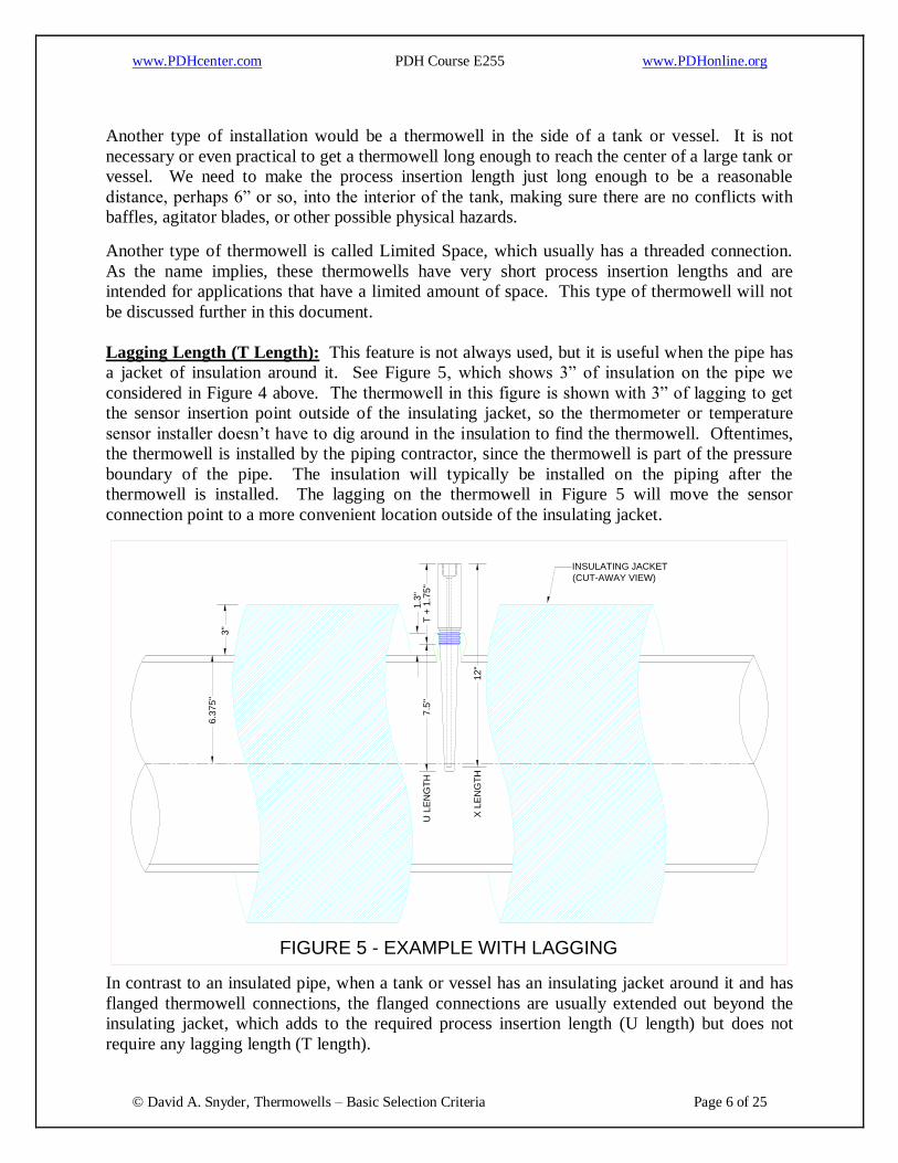
Lagging Length (T Length): This feature is not always used, but it is useful when the pipe has
a jacket of insulation around it. See Figure 5, which shows 3” of insulation on the pipe we
considered in Figure 4 above. The thermowell in this figure is shown with 3” of lagging to get
the sensor insertion point outside of the insulating jacket, so the thermometer or temperature
sensor installer doesn‟t have to dig around in the insulation to find the thermowell. Oftentimes,
the thermowell is installed by the piping contractor, since the thermowell is part of the pressure
boundary of the pipe. The insulation will typically be installed on the piping after the
thermowell is installed. The lagging on the thermowell in Figure 5 will move the sensor
connection point to a more convenient location outside of the insulating jacket.
FIGURE 5 - EXAMPLE WITH LAGGING
6.3
75"
3"
12"
1.3
" 7.5
"
INSULATING JACKET
(CUT-AWAY VIEW)
U L
EN
GT
H
X L
EN
GT
H
T +
1.7
5"
In contrast to an insulated pipe, when a tank or vessel has an insulating jacket around it and has
flanged thermowell connections, the flanged connections are usually extended out beyond the
insulating jacket, which adds to the required process insertion length (U length) but does not
require any lagging length (T length).
www.PDHcenter.com PDH Course E255 www.PDHonline.org
© David A. Snyder, Thermowells – Basic Selection Criteria Page 7 of 25
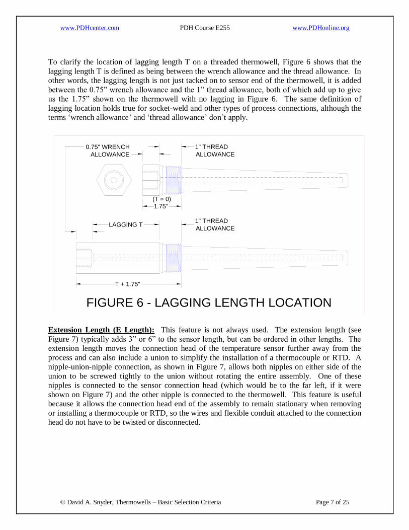
To clarify the location of lagging length T on a threaded thermowell, Figure 6 shows that the
lagging length T is defined as being between the wrench allowance and the thread allowance. In
other words, the lagging length is not just tacked on to sensor end of the thermowell, it is added
between the 0.75” wrench allowance and the 1” thread allowance, both of which add up to give
us the 1.75” shown on the thermowell with no lagging in Figure 6. The same definition of
lagging location holds true for socket-weld and other types of process connections, although the
terms „wrench allowance‟ and „thread allowance‟ don‟t apply.
FIGURE 6 - LAGGING LENGTH LOCATION
1.75"
T + 1.75"
(T = 0)
1" THREAD
ALLOWANCE
0.75" WRENCH
ALLOWANCE
1" THREAD
ALLOWANCELAGGING T
Extension Length (E Length): This feature is not always used. The extension length (see
Figure 7) typically adds 3” or 6” to the sensor length, but can be ordered in other lengths. The
extension length moves the connection head of the temperature sensor further away from the
process and can also include a union to simplify the installation of a thermocouple or RTD. A
nipple-union-nipple connection, as shown in Figure 7, allows both nipples on either side of the
union to be screwed tightly to the union without rotating the entire assembly. One of these
nipples is connected to the sensor connection head (which would be to the far left, if it were
shown on Figure 7) and the other nipple is connected to the thermowell. This feature is useful
because it allows the connection head end of the assembly to remain stationary when removing
or installing a thermocouple or RTD, so the wires and flexible conduit attached to the connection
head do not have to be twisted or disconnected.

www.PDHcenter.com PDH Course E255 www.PDHonline.org
© David A. Snyder, Thermowells – Basic Selection Criteria Page 8 of 25
FIGURE 7 - THREADED, TAPERED, WITH 6" EXTENSION
0.25"
X = SENSOR LENGTHU = PROCESS INSERTION LENGTH T + 1.75" E = EXTENSION LENGTH
NIPPLE NIPPLEUNION
6" EFFECTIVE LENGTH
Sensor Length (X Length, Sometimes Called S Length): This is how long a temperature
sensor or thermometer bulb needs to be in order for the tip of the sensor or bulb to touch the
process end of the bore inside the thermowell. To phrase it differently, the tip of the sensor or
bulb needs to be touching the process end of the thermowell in order to get good temperature
transfer from the thermowell to the sensor or bulb. If there were a gap between the thermowell
and the tip of the sensor or bulb, then the accuracy of the temperature reading would suffer.
Very often, RTDs are specified as spring-loaded to ensure that the tip of the RTD is touching the
process end of the bore.
In order to determine the sensor length, we need to factor in all of the lengths (Extension [E],
Lagging [T], Process Insertion [U]) that are discussed above, plus the distance from the process
connection to the beginning of the threads for the temperature sensor or thermometer. The
formulas for determining sensor length are simple, but there are two different styles, depending
on the type of process connection:
1) Most Types of Process Connections:
X = E + T + U + 1.75” – 0.25”, which is usually simplified and represented as:
X = E + T + U + 1.5”
Take a look at Figure 7, which shows all of the lengths, X, E, T, and U, as well as the
1.75” and 0.25” lengths.
2) Flanged Process Connections:
X = E + T + U + 2.25” – 0.25”, which is usually simplified and represented as:
X = E + T + U + 2”
Let‟s start with the first formula, in item 1) Most Types of Process Connections above. The
1.75” length is shown in the T = 0 (no lagging) examples in Figures 1 and 2 as the distance from
the process connection to the beginning of the threads for the temperature sensor or thermometer.

www.PDHcenter.com PDH Course E255 www.PDHonline.org
© David A. Snyder, Thermowells – Basic Selection Criteria Page 9 of 25
The 0.25” is shown as the distance from the outside tip of the thermowell to the inside end of the
internal bore of the thermowell. The + 1.75” and the – 0.25” are usually combined into a single
value of + 1.5”.
Let‟s examine the simplified case shown in Figure 4, where there is no extension length E, no
lagging length T, and we are using a threaded process connection. In this case, we have:
X = E + T + U + 1.75” – 0.25”
X = 0” + 0” + U + 1.75” – 0.25”.
X = U + 1.5”
X = 7.5” + 1.5”
X = 9”
As can be seen from the cut-sheets (Attachments G and H), this is a standard offering for sensor
or thermometer length.
Consider the example in Figure 5, which has no extension length, but a lagging length T = 3”
and a threaded process connection. The sensor length would be, as before:
X = E + T + U + 1.75” – 0.25”
X = 0” + T + U + 1.5”
X = 0” + 3” + 7.5” + 1.5” = 12”.
As can be seen from the cut-sheets (Attachments G and H), a temperature sensor or thermometer
length of 12” is a standard offering.
Now, let‟s consider an application with a flanged process connection, for which the sensor length
formula appears in item 2) Flanged Process Connections on page 8. As can be seen in the T = 0
(no lagging) example in Figure 3, instead of a distance of 1.75” from the process connection to
the sensor connection, we now have a distance of 2.25”. That means our new sensor length
formula is:
X = E + T + U + 2.25” – 0.25”, which can be simplified as:
X = E + T + U + 2”
This 2.25” distance for flanged thermowells is 0.5” longer than the 1.75” distance for the other
process connection types, but the standard process insertion lengths for flanged thermowells are
typically 0.5” shorter than those for other types of process connections, so the resulting sensor
length is unaffected. In other words, while a 7.5” process insertion length is standard for other

www.PDHcenter.com PDH Course E255 www.PDHonline.org
© David A. Snyder, Thermowells – Basic Selection Criteria Page 10 of 25
types of process connections, a 7” process insertion length is standard for flanged process
connections.
For this example, we‟ll have no extension length (E = 0), a lagging length T = 3”, a process
insertion length U = 7”, and a flanged process connection. The sensor length X will be:
X = E + T + U + 2”
X = 0” + 3” + 7” + 2”
X = 12”
This is the same sensor length as the threaded example illustrated in Figure 5, but the process
insertion length is 0.5” shorter.
Let‟s consider one more example for a flanged thermowell, this one with a 13” process insertion
length U, a 3” lagging length T, and a 6” extension length E. As we learned above (though we
always confirm with the cut-sheets), the sensor length X for this type of process connection is:
X = E + T + U + 2”
X = 6” + 3” + 13” + 2”
X = 24”
As can be seen on the cut-sheets (Attachments G and H), this thermometer or sensor length is a
standard offering. Non-standard temperature sensor and thermometer bulb lengths are available,
but specifying non-standard devices can sometimes add to the cost and delivery time.
Tables 2 and 3 list the most popular combinations of process insertion length U, lagging length
T, extension length E, and resulting sensor length X for the two main types of process
connections, namely a) flanged and b) everything else. Some companies will list additional
choices for standard lengths.

www.PDHcenter.com PDH Course E255 www.PDHonline.org
© David A. Snyder, Thermowells – Basic Selection Criteria Page 11 of 25
TABLE 2 -- FLANGED THERMOWELLS
PROCESS
INSERTION
LENGTH
U (INCHES)
LAGGING LENGTH
T (INCHES)
EXTENSION
E (INCHES)
SENSOR LENGTH
X (INCHES)
= E + T + U + 2”
2 0 0 4
2 2 0 6
2 2 3 9
2 2 6 12
--- --- --- ---
4 0 0 6
4 3 0 9
4 3 3 12
4 3 6 15
--- --- --- ---
7 0 0 9
7 3 0 12
7 3 3 15
7 3 6 18
--- --- --- ---
10 0 0 12
10 3 0 15
10 3 3 18
10 3 6 21 (NON-STD.)
--- --- --- ---
13 0 0 15
13 3 0 18
13 3 3 21 (NON-STD.)
13 3 6 24
--- --- --- ---
16 0 0 18
16 3 0 21 (NON-STD.)
16 3 3 24
16 3 6 27 (NON-STD.)
--- --- --- ---
22 0 0 24
22 3 0 27 (NON-STD.)
22 3 3 30 (NON-STD.)
22 3 6 33 (NON-STD.)
Note: Standard lagging lengths are not typically listed on cut-sheets for flanged thermowells.

www.PDHcenter.com PDH Course E255 www.PDHonline.org
© David A. Snyder, Thermowells – Basic Selection Criteria Page 12 of 25
TABLE 3 -- THREADED, SOCKET WELD, AND OTHER TYPES OF THERMOWELLS
PROCESS
INSERTION
LENGTH
U (INCHES)
LAGGING LENGTH
T (INCHES)
EXTENSION
E (INCHES)
SENSOR LENGTH
X (INCHES)
= E + T + U + 1.5”
2.5 0 0 4
2.5 2 0 6
2.5 2 3 9
2.5 2 6 12
--- --- --- ---
4.5 0 0 6
4.5 3 0 9
4.5 3 3 12
4.5 3 6 15
--- --- --- ---
7.5 0 0 9
7.5 3 0 12
7.5 3 3 15
7.5 3 6 18
--- --- --- ---
10.5 0 0 12
10.5 3 0 15
10.5 3 3 18
10.5 3 6 21 (NON-STD.)
--- --- --- ---
13.5 0 0 15
13.5 3 0 18
13.5 3 3 21 (NON-STD.)
13.5 3 6 24
--- --- --- ---
16.5 0 0 18
16.5 3 0 21 (NON-STD.)
16.5 3 3 24
16.5 3 6 27 (NON-STD.)
--- --- --- ---
22.5 0 0 24
22.5 3 0 27 (NON-STD.)
22.5 3 3 30 (NON-STD.)
22.5 3 6 33 (NON-STD.)

www.PDHcenter.com PDH Course E255 www.PDHonline.org
© David A. Snyder, Thermowells – Basic Selection Criteria Page 13 of 25
Interior Diameter (Bore): This is the diameter
or bore of the hole that is drilled in to the solid
bar stock of the thermowell raw material to
create the cavity for the temperature sensor or
thermometer stem to be inserted. The two most
popular choices for interior diameter are 0.26”
and 0.385”.
The 0.26” diameter bore will accommodate a
0.25” (1/4”) diameter temperature sensor, such
as an RTD. The extra 0.01” (0.005” all around)
in the 0.26” diameter bore provides enough
room to allow the 0.25” diameter sensor to slide
in to the thermowell.
Similarly, the 0.385” diameter bore is intended
for a 0.375” (3/8”) diameter thermometer stem
or bulb. Other interior diameters are available.
Internal Threads: This is the connection
for the temperature sensor or thermometer.
It is often 0.5” NPSM female (see Some
Pipe Thread Types sidebar), but could be
0.5” NPT female or some other connection
type. The 0.5” NPT male connector on
the temperature sensor or thermometer
will fit both the 0.5” NPSM female
connection and the 0.5” NPT female
connection, so either internal thread type
is acceptable. The temperature sensor or
thermometer will slide into the thermowell
and then be tightened to this internal
thread. If an extension is used, the process
end of the extension will be tightened to
this internal thread, rather than the
temperature sensor or thermometer (see
Figure 7).
The funny-looking W-shape at the process end
of the bore inside the thermowell is the result of
the 0.26” or 0.385” bore being formed by a gun
drill. The deepest part of the gun drill bit is
offset from the center of the gun drill such that
the deepest part of the bore is about one-half of
the radius from the center of the bore. This
creates a bore hole that has a raised cone at the
center with a V-shaped trough encircling it.
THERMO-
WELL
GUN
DRILL
Some Pipe Thread Types:
NPT, in spite of what many people think, is actually
the abbreviation for National Pipe Taper, not
National Pipe Thread. There are several different
types of American national pipe thread defined in the
ASME B1.20.1 standard, including tapered (NPT),
straight coupling (NPSC), and straight mechanical
(NPSM). If the T in NPT stood for thread, there
would be a T in each of the thread standard
acronyms.
The tapered threads of male NPT connections have a
diameter that gets larger and the tapered threads of
female NPT connections have a diameter that gets
smaller as the male fitting is screwed in to the female
fitting, thus making the connection tighter and
tighter.
NPSM is the National Pipe Straight Mechanical
thread standard. It is similar to the tapered (NPT)
standard (same pitch and thread flank angle), except
that the threads are straight, not tapered. That is,
the diameter of the threads does not change.

www.PDHcenter.com PDH Course E255 www.PDHonline.org
© David A. Snyder, Thermowells – Basic Selection Criteria Page 14 of 25
Shape of Thermowell: This is the shape or stem geometry or shank style of the process portion
of the thermowell. The four main types are straight (Figure 8), stepped (Figure 9), tapered
(Figures 1, 2, and 3), and built-up (not shown).
1) Straight thermowells (Figure 8) have good rigidity and are the simplest shape to
fabricate. As the name implies, the outer diameter of the thermowell is the same from
the process end of the thermowell to the process connection. Straight thermowells are
almost always available with a 0.385” bore, and sometimes with 0.26”.
2) Stepped thermowells (Figure 9) have a smaller diameter at the process end than at the
process connection. This change in diameter takes place in one step, rather than
being smoothly tapered. The small diameter of the process end of this thermowell
results in decreased thermal inertia and can therefore respond more quickly to
changes in temperature than a straight thermowell. Stepped thermowells are typically
available with a 0.26” bore, not 0.385”.
3) Tapered thermowells (Figures 1, 2, and 3) also have a smaller diameter at the process
end than at the process connection. This change in diameter takes places in a smooth,
continuous taper. Due to the smaller diameter of its tapered tip, this type of
thermowell can react more quickly to changes in temperature than a straight
thermowell and has the added advantage of high rigidity. This type of thermowell is
typically used in heavy-duty as well as general-purpose applications. Tapered
thermowells are available with a 0.26” or 0.385” bore.
4) Built-up thermowells are used for very long (typically 22” or more) process insertion
lengths (U length). They are available with the same process connections and process
ends (stem geometry) as the above thermowells, but a length of pipe is welded
between the process connection and the process end to give the required process
insertion length.

www.PDHcenter.com PDH Course E255 www.PDHonline.org
© David A. Snyder, Thermowells – Basic Selection Criteria Page 15 of 25
FIGURE 8 - THREADED, STRAIGHT
INTERIOR
DIAMETER
(BORE)
INTERNAL
THREADS
HEX FITTING
THREADED PROCESS
CONNECTION
INTERIOR
DIAMETER
(BORE)
0.25"U = PROCESS INSERTION LENGTH 1.75"
0.25"T + 1.75" U = PROCESS INSERTION LENGTH
(T = 0)
X = SENSOR LENGTH
X = SENSOR LENGTH
FIGURE 9 - THREADED, STEPPED
INTERIOR
DIAMETER
(BORE)
INTERNAL
THREADS
HEX FITTING
THREADED PROCESS
CONNECTION
INTERIOR
DIAMETER
(BORE)
0.25"U = PROCESS INSERTION LENGTH 1.75"
0.25"T + 1.75" U = PROCESS INSERTION LENGTH
(T = 0)
2.5"
X = SENSOR LENGTH
X = SENSOR LENGTH

www.PDHcenter.com PDH Course E255 www.PDHonline.org
© David A. Snyder, Thermowells – Basic Selection Criteria Page 16 of 25
Material of Construction: Thermowells can be fabricated from a variety of metals, the most
popular of which include brass, carbon steel, 304 stainless steel, and 316 stainless steel. Other
material choices include aluminum, monel, Hastelloy C and titanium, to name a few. The choice
of material depends on the process medium, thermowell cost, and thermowell delivery time.
Two popular all-around choices for material of construction are 304 or 316 stainless steel, since
these materials are compatible with a great many processes and thermowells constructed from
these materials are readily available.
To determine the best choice for the material of construction of the thermowell, consult the
manufacturer‟s material compatibility or corrosive service guide such as shown in Attachment I.
For example, 304 stainless steel is recommended for ethylene glycol and 316 stainless steel is
recommended for titanium tetrachloride in this attachment.
Additional Considerations: Fluids flowing past the thermowell will put a bending force on the
thermowell. Additionally, fluids traveling transverse or perpendicular to a thermowell will
generate a wake of a certain frequency, based on the fluid velocity and diameter of the
thermowell. This wake will cause the thermowell to vibrate. Ordinarily, these vibrations are
negligible, until the vibrations approach the natural frequency of the thermowell. Each
thermowell has a natural or resonant frequency, based on the length of the thermowell and the
material from which it is fabricated. The formulas for these frequencies can be used to
determine if a particular thermowell is acceptable in a given application (see ASME publication
PTC 19.3). Many thermowell manufacturers have tabulated the approximate velocity rating of
each of their standard thermocouples, based on assumptions for the maximum process
temperature and the type of fluid. Contact your thermowell vendor or search the internet for
“thermowell velocity rating” (quotes omitted) for additional information.
In Closing: The information presented in this document is intended to represent the standard
offerings from leading thermowell manufacturers. In every case, the specifier should confirm
the exact dimensions and standard offerings from the selected manufacturer and model cut-sheet.
ATTACHMENTS FOLLOW AND ARE INCLUDED BY PERMISSION

www.PDHcenter.com PDH Course E255 www.PDHonline.org
© David A. Snyder, Thermowells – Basic Selection Criteria Page 17 of 25
Attachment A

www.PDHcenter.com PDH Course E255 www.PDHonline.org
© David A. Snyder, Thermowells – Basic Selection Criteria Page 18 of 25
Attachment B
www.PDHcenter.com PDH Course E255 www.PDHonline.org
© David A. Snyder, Thermowells – Basic Selection Criteria Page 19 of 25
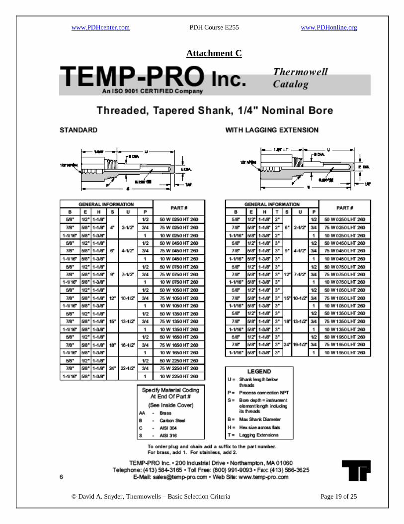
Attachment C
www.PDHcenter.com PDH Course E255 www.PDHonline.org
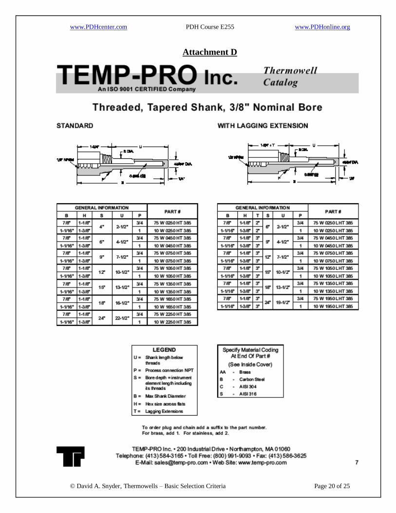
© David A. Snyder, Thermowells – Basic Selection Criteria Page 20 of 25
Attachment D

www.PDHcenter.com PDH Course E255 www.PDHonline.org
© David A. Snyder, Thermowells – Basic Selection Criteria Page 21 of 25
Attachment E

www.PDHcenter.com PDH Course E255 www.PDHonline.org
© David A. Snyder, Thermowells – Basic Selection Criteria Page 22 of 25
Attachment F

www.PDHcenter.com PDH Course E255 www.PDHonline.org
© David A. Snyder, Thermowells – Basic Selection Criteria Page 23 of 25
Attachment G

www.PDHcenter.com PDH Course E255 www.PDHonline.org
© David A. Snyder, Thermowells – Basic Selection Criteria Page 24 of 25
Attachment H

www.PDHcenter.com PDH Course E255 www.PDHonline.org
© David A. Snyder, Thermowells – Basic Selection Criteria Page 25 of 25
Attachment I