THERMOMECHANICAL PULPING -...
4
APPLICATION REPORT 2621/06/01 EN • 12/2011 THERMOMECHANICAL PULPING Overview of the process Thermomechanical pulping, TMP, is precisely named. Pulp is made by heating the chips with steam and mechanically separating the fibers in a pressurized refiner. While high in energy consumption, TMP produces strong fibers, and clean steam can be recovered. The process Chips are fed to a presteamer and are steamed with process steam from the refiners. A feed- ing screw (plug feeder) moves the chips to a pressurized refiner which separates the fiber via mechanical means (e.g. between rotating disc plates). The refiner is followed by a cyclone to separate the pulp from the process steam. The pulp is of- ten refined in two stages. The process steam is taken to the heat recovery unit to produce clean steam.
Transcript of THERMOMECHANICAL PULPING -...
APPLICATION REPORT2621/06/01 E
N • 12/2011
THERMOMECHANICAL PULPING
Overview of the processThermomechanical pulping, TMP, is precisely named. Pulp is made by heating the chips with steam and mechanically separating the fibers in a pressurized refiner. While high in energy consumption, TMP produces strong fibers, and clean steam can be recovered.
The processChips are fed to a presteamer and are steamed with process steam from the refiners. A feed-ing screw (plug feeder) moves the chips to a pressurized refiner which separates the fiber via mechanical means (e.g. between rotating disc plates).
The refiner is followed by a cyclone to separate the pulp from the process steam. The pulp is of-ten refined in two stages. The process steam is taken to the heat recovery unit to produce clean steam.
2621/06/01 EN THERMOMECHANICAL PULPING
2 APPLICATION REPORT 12/11
The resultsThe Pre-steamer is heated with the process steam via valve PCV-1 to typically 1 to 2 bar or 130 to 140 °C (15 to 30 psig, 266 to 284 °F). After a retention time of couple minutes, the pressur-ized chips is fed to the refiner. The refiner may be fed with fresh steam via valve PCV-4, during startup, to increase the pressure up to 4...5 barg or 150 °C (60...75 psig or 300 °F).
The refiner discharges the pulp and steam to a cyclone. The cyclone separates the steam from the pulp. The valves (PCV-1, PCV-2) in the process steam line control the pressure in the refiner. During production this steam is sent to heat recovery, while in the start-up it goes to the steam stack for disposal. The TMP pulp (35 %) is discharged through valve PCV-3 from the first stage refiner to the second stage and from there to further treatment in the screening, cleaning etc.
Valve selectionThe control of fresh steam in PCV-4 can be eas-ily accomplished by the R series segment valve. The process steam, however, has a tendency to contain ersin end fibers which can build up and result in potential plugging problems in valves PCV-1 and PCV-2. Neldisc® has performed well in this application. Because of fines and fibers present the use of Q-Trims in the process steam must be evaluated with care.
The TMP discharge (blow) valve PCV-3 contains TMP pulp (35 % consistency), and steam/con-densate. Because of the high pressure drop of the system, this valve must withstand erosion. One solution is a segment type valve, flanged, expanded outlet with stellited internals. Also metal seated ball valves are used. The water (white or fresh) control valve should all be R se-ries segment valves for optimal control.
Not shown in the drawing is a refiner relief valve which will discharge the refiner contents quickly when needed to protect the refiner (exceeding a set pressure, broken plates, etc.). Full bore ball valve, M series, with locked seats (P) equipped with a fail open quick action actuator should be selected.
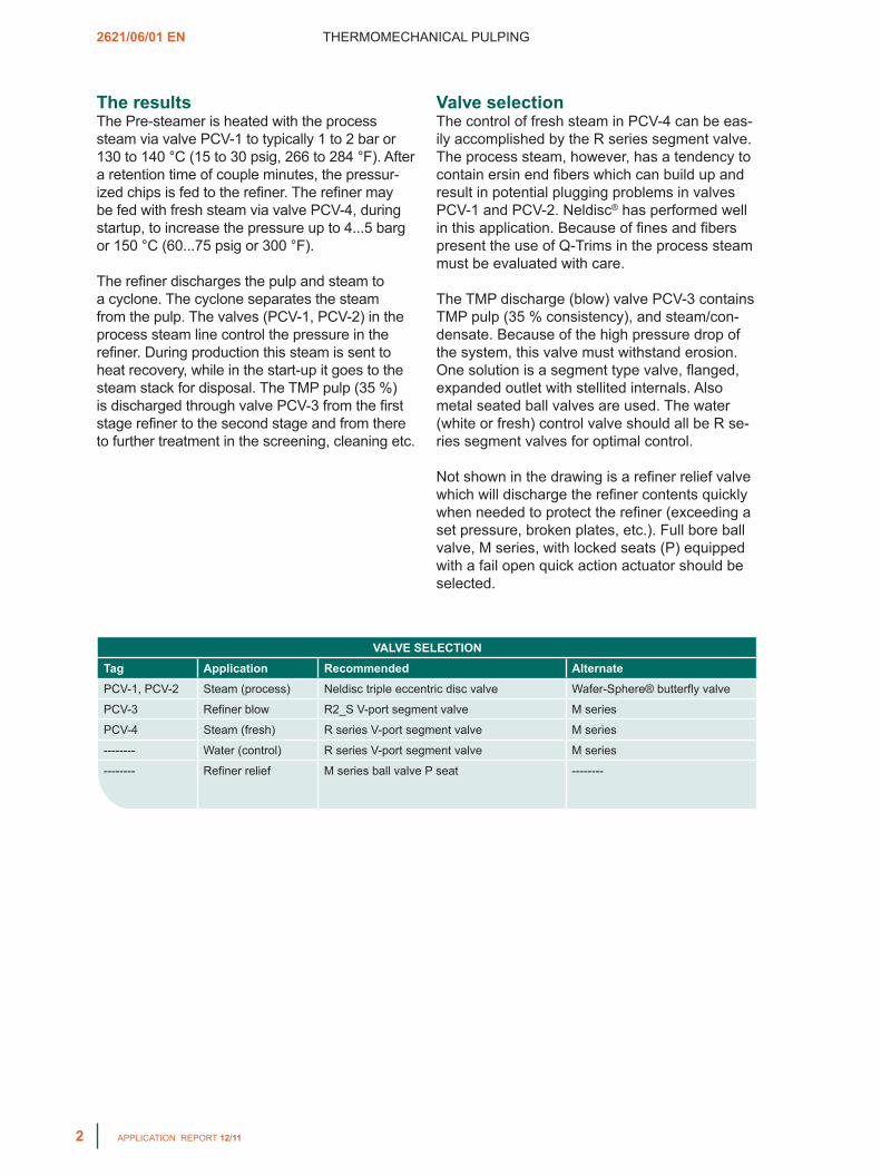
VALVE SELECTION
Tag Application Recommended AlternatePCV-1, PCV-2 Steam (process) Neldisc triple eccentric disc valve Wafer-Sphere® butterfly valve
PCV-3 Refiner blow R2_S V-port segment valve M series
PCV-4 Steam (fresh) R series V-port segment valve M series
-------- Water (control) R series V-port segment valve M series
-------- Refiner relief M series ball valve P seat --------

THERMOMECHANICAL PULPING 2621/06/01 EN
APPLICATION REPORT 12/11 3
Figure 1. The two stage TMP system.
Neldisc butterfly valve
M series ball valve
Wafer-Sphere butterfly valve
R series V-port segment valve

The information provided in this bulletin is advisory in nature, and is intended as a guideline only. For specific circumstances and more detailed information, please consult with your local automation expert at Metso.
Metso Automation Inc.Europe, Vanha Porvoontie 229, P.O. Box 304, FI-01301 VANTAA, Finland. Tel. +358 20 483 150. Fax +358 20 483 151North America, 44 Bowditch Drive, P.O. Box 8044, Shrewsbury, MA 01545, USA. Tel. +1 508 852 0200. Fax +1 508 852 8172South America, Av. Independéncia, 2500- Iporanga, 18087-101, Sorocaba-São Paulo Brazil. Tel. +55 15 2102 9700. Fax +55 15 2102 9748/49Asia Pacific, 20 Kallang Avenue, Lobby B, #06-00, PICO Creative Centre, Singapore 339411, Singapore. Tel. +65 6511 1011. Fax +65 6250 0830 China, 19/F, the Exchange Beijing, No. 118, Jianguo Lu Yi, Chaoyang Dist, 100022 Beijing, China. Tel. +86-10-6566-6600. Fax +86-10-6566-2575Middle East, Roundabout 8, Unit AB-07, P.O. Box 17175, Jebel Ali Freezone, Dubai, United Arab Emirates. Tel. +971 4 883 6974. Fax +971 4 883 6836www.metso.com/valves
APPLICATION REPORT