THERMOELECTRIC PRODUCTS CATALOGUE - Crystal LTD - Thermoelectric · PDF file ·...
28
THERMOELECTRIC PRODUCTS CATALOGUE CRYSTAL LTD. 2014
Transcript of THERMOELECTRIC PRODUCTS CATALOGUE - Crystal LTD - Thermoelectric · PDF file ·...

THERMOELECTRIC PRODUCTS CATALOGUE
CRYSTAL LTD. 2014


1
TABLE OF CONTENTS:
THE COMPANY . . . . . . . . . . . . . . . . . . . . . . . . . . . . . . . . . . . . . . . . . . . . . . 4
TECHNOLOGY OF THERMOELECTRIC MATERIAL PRODUCTION . . . . . . . . . . . . . . 6
TECHNOLOGY OF THERMOELECTRIC MODULES MANUFACTURING . . . . . . . . . . . 7
QUALITY SYSTEM . . . . . . . . . . . . . . . . . . . . . . . . . . . . . . . . . . . . . . . . . . . . . 8
THERMOELECTRIC ELEMENTS . . . . . . . . . . . . . . . . . . . . . . . . . . . . . . . . . . . . 9
THERMOELECTRIC MODULES . . . . . . . . . . . . . . . . . . . . . . . . . . . . . . . . . . . .12
THERMAL MANAGEMENT ACCESSORIES: . . . . . . . . . . . . . . . . . . . . . . . . . . . . .23

2
Smart cooling for comfortable life
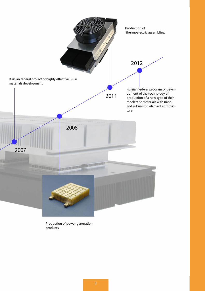
3

4
THE COMPANY
Crystal Ltd . was founded in 1995 on the base of Moscow Steel and Alloys Institute (Moscow Technical Uni-versity) to establish a mass production technology of high quality thermoelectric (TE) materials (pellets) by modified Bridgeman method for thermoelectric modules and assemblies .
Crystal Ltd . is one of the world’s leaders in thermoelectric market . We have many years of experience in pro-duction of thermoelectric materials, based on Bismuth Telluride solid solutions, and thermoelectric cooling and power generation modules .
We have an enormous experience of international cooperation and we are able to perform full cycle of works: from research and development to sales of new types of thermoelectric products in the field of direct energy conversion and thermal management . All works are performed in our own sites .
Our products are widely distributed due to a unique combination of high performance and attractive price, thus giving the possibility to obtain optimal solutions in the field of thermoelectric converters with the best price/quality ratio .
COMPANY STRUCTURE
1). Central office. Commercial, marketing and financial department in Korolev city (Moscow Region)
2). Crystal Pland Ltd. – mass production plant in Bogoroditsk city (Tula Region)
3). Thermoelectric materials R&D department in Mosrentgen town (Moscow)
4). Thermal management products R&D department in Bogoroditsk city (Tula Region)
4). Crystal Trade House – subsidiary company, focused on sales, based in Novomoskovsk city (Tula Region) .
5). Official distributor in USA and Asia region: Align Sourcing LLC (USA)
6). Official distributor (Spain and South America) Mondragon (Spain)
7). Official distributor (Israel) Beewen (Israel).
GEOGRAPHY OF SALES:

5
OUR MISSION:
INTELLIGENT COOLING FOR COMFORTABLE LIFE
OUR PRIORITIES:
— INTEGRATION OF ECO-FRIENDLY CLIMAT-IC AND POWER GENERATION SYSTEMS AND COMPONENTS TO EVERYDAY LIFE.
— IMPROVEMENT OF THERMOELECTRIC PRODUCTS BY IMPLEMENTATION OF RESEARCH AND DE-VELOPMENT WORKS TO MASS PRODUCTION.
— SUPPLY OF THERMOELECTRIC COOL-ING AND POWER GENERATION PRODUCTS TO SUCH HIGH-END APPLICATIONS AS:
TELECOMMUNICATIONS;
MEDICAL AND COSMETICAL EQUIPMENT;
AUTOMOTIVE AND RAILWAY TRANSPORT;
MILITARY DEVICES AND EQUIPMENT;
ANALYTICAL EQUIPMENT AND TEST BENCHES;
POWER SUPPLY FOR WIRELESS SENSORS NETWORK;
EFFICIENT ENERGY HARVESTING SYSTEMS;
EQUIPMENT FOR SPACE AND AVIATION
HOUSEHOLD COOLERS WITHOUT COMPRESSION SYSTEM
— PROMOTION OF HIGH-QUALITY THERMO-ELECTRIC PRODUCTS OF CRYSTAL TO THE GLOBAL MARKET THROUGH DIRECT SALES AND REPRESENTATIVES NETWORK
6
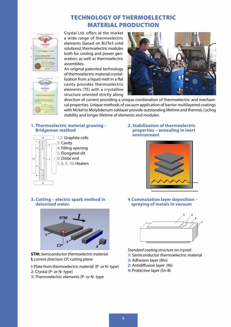
TECHNOLOGY OF THERMOELECTRIC MATERIAL PRODUCTION
Crystal Ltd . offers at the market a wide range of thermoelectric elements (based on Bi2Te3 solid solutions), thermoelectric modules both for cooling and power gen-eration, as well as thermoelectric assemblies . An original patented technology of thermoelectric material crystal-lization from a liquid melt in a flat cavity provides thermoelectric elements (TE) with a crystalline structure oriented strictly along direction of current providing a unique combination of thermoelectric and mechani-cal properties . Unique methods of vacuum application of barrier multilayered coatings with Nickel to Molybdenum sublayer provide outstanding lifetime and thermal, cycling stability and longer lifetime of elements and modules .
1. Thermoelectric material growing – Bridgeman method
1,2: Graphite cells3: Cavity 4: Filling opening5: Elongated slit 6: Distal end7, 8, 9, 10: Heaters
2. Stabilization of thermoelectric properties – annealing in inert environment
3. Cutting – electric spark method in deionized water.
STM: Semiconductor thermoelectric material. I: current direction; CP: cutting plane
I: Plate from thermoelectric material (P- or N- type)2: Crystal (P- or N- type)3: Thermoelectric elements (P- or N- type
4 Commutation layer deposition – spraying of metals in vacuum
Standard coating structure on crystal:1: Semiconductor thermoelectric material2: Adhesion layer (Мо)3: Antidiffusion layer (Ni)4: Protective layer (Sn-Bi

7
OPERATING CHARACTERISTICS OF THERMOELECTRIC MATERIAL
Dependence of electric conductivity from tem-perature for N-type material . .
Dependence of electric conductivity from tem-perature for P-type material . .
Dependence of Z from temperature for N-type material . Dependence of Z from temperature for P-type
material .
TECHNOLOGY OF THERMOELECTRIC MODULES MANUFACTURING
1. Thermoelectric elements placement – po-sitioning on ceramic substrates by automatic assembly machine .
2. Assembly of thermoelectric modules – group soldering of semiconductor elements with soldering paste .
3. Thermoelectric modules finishing – bilateral free abrasive polishing .
4. Protection from exposure of environment – sealing with epoxy or silicone resin

8
QUALITY SYSTEM.
Our company is proud of the quality of our products . The main objective of the quality control system in Crystal is to achieve full compliance of our products to specifications . Our quality control system is based on years of experience in production activities .
Quality begins from our suppliers – we work only with reliable partners . Arriving to the production site, raw materials and components are passing input control . Our unique technology allows to grow thermoelec-tric materials controlling 100% of their properties . As a result, we produce thermoelectric elements with excellent parameters, which are the basis of the quality of our thermoelectric modules . Several procedures of preliminary complete control of modules on the main stages of the process, as well as complete output control ensure that the customer will receive only high-quality modules, which conform to the relevant specifications .
• Quality Assurance System is integrated to all processes of our company . Staff, not motivated by pro-duction volume, performs quality control of products and passes regular trainings on quality assur-ance system;
• Each lot of product is traced during production process at every stage . During technological process every unit of production can also be traced, if necessary;
• Stable process, which provides guaranteed high quality of our products, is controlled by the organiza-tional procedures of the system and verified by periodic testing of finished products .
9
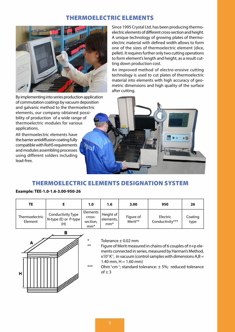
THERMOELECTRIC ELEMENTSSince 1995 Crystal Ltd . has been producing thermo-electric elements of different cross-section and height . A unique technology of growing plates of thermo-electric material with defined width allows to form one of the sizes of thermoelectric element (dice, pellet) . It requires further only two cutting operations to form element’s length and height, as a result cut-ting down production cost . An improved method of electro-erosive cutting technology is used to cut plates of thermoelectric material into elements with high accuracy of geo-metric dimensions and high quality of the surface after cutting .
By implementing into series production application of commutation coatings by vacuum deposition and galvanic method to the thermoelectric elements, our company obtained possi-bility of production of a wide range of thermoelectric modules for various applications . All thermoelectric elements have the barrier antidiffusion coating fully compatible with RoHS requirements and modules assembling processes using different solders including lead-free .
THERMOELECTRIC ELEMENTS DESIGNATION SYSTEMExample: ТЕЕ-1.0-1.6-3.00-950-26
TE E 1.0 1.6 3.00 950 26
Thermoelectric Element
Conductivity Type N-type (E) or P-type
(H)
Elements cross-
section, mm*
Height of elements,
mm*
Figure of Merit**
Electric Conductivity***
Coating type
* Tolerance ± 0 .02 mm** Figure of Merit measured in chains of 6 couples of n+p ele-
ments connected in series, measured by Harman’s Method, x103 K-1, in vacuum (control samples with dimensions A,B = 1 .40 mm, H = 1 .60 mm)
*** Ohm-1cm-1; standard tolerance: ± 5%; reduced tolerance of ± 3

10
THERMOELECTRIC ELEMENTS COATING TYPES
TYPE “6M” The elements with this coating are used to assemble the modules for traditional cooling applications with operation temperature up to 900C . A solder with melting point 140-1800C is recommended for the assembling process . The coating composition: Nickel, Ni: 4 .0 ± 1 .0 micron Tin-Bismuth, Sn-Bi (Bi < 1%): 4 .0 ± 1 .0 micron
TYPE “26”The elements with this coating are used to assemble the modules for applications with operation tempera-ture up to 1100C . The coating is applied by the magnetron for better uniformity and thickness repeatability of the metallic layer . The preliminary etching of the working surface of the element and molybdenum film provide better adhesive strength of the coating . A solder with melting point up to 2400C is recommended for the assembling process .The coating composition: Molybdenum, Mo: 0 .05 ± 0 .02 micron Nickel, Ni 4 .0 ± 1 .0 micron Tin-Bismuth, Sn-Bi (Bi < 1%): 4 .0 ± 1 .0 micron
TYPE “5B”The elements with this coating are used to assemble the modules for applications with operation tem-perature up to 1200C and long-term “ON/OFF” operational mode . A solder with melting point up to 2400C is recommended for the assembling processThe coating composition: Molybdenum, Mo: 0 .05 ± 0 .02 micron Nickel, Ni: 5 .0 ± 1 .0 micron Tin-Bismuth, Sn-Bi (Bi < 1%): 7 .0 ± 1 .0 micron
TYPE “6B”The elements with this coating are used to assemble the modules for cooling applications with operation temperature up to 1500C . A solder with melting point up to 2500C is recommended for the assembling process .The coating composition: Molybdenum, Mo: 0 .05 ± 0 .02 micron Nickel, Ni: 10 .0 ± 1 .0 micron Tin-Bismuth, Sn-Bi (Bi < 1%): 7 .0 ± 1 .0 micron

11
THERMOELECTRIC MODULES
Thermoelectric module is a semiconductor-based solid-state device, which is used to convert electrical energy into temperature differential (heat pump, operating on Peltier effect) or, vice versa, thermal energy of temperature difference into electric power (Seebeck effect) .
Thermoelectric module (TEM) consists of p-type and n-type semiconductor elements (dices, pellets), com-mutated by copper plates and sandwiched between two ceramic substrates . Constant electric current flows through the circuit of elements, commutated in series, and moves heat from the “cold” side to the “hot” side . As a result, one side of TEM is cooled, the opposite side is heated . In the case of reversed direction of the current, heat flux also changes its direction, that is, the cold plate is heated, and hot - cooled .
The number of thermoelectric elements may vary from several elements to hundreds . This allows designing a TEM with a desirable cooling power . By cascading thermoelements a significant increase in dT (tempera-ture difference between hot and cold sides) can be achieved .
Thermoelectric modules have several features, which allow them to replace traditional compressor-based coolers in many applications: • Small size; • No moving parts, as a result – no noise and vibration; • High reliability and endless period of storage; • Reasonable price; • In contrast to conventional chillers - the invariance of a short circuit . • RoHS compatible, lead free; • Coolant-free - green technology; • Option of cooling and heating in one device; • Silicon or Epoxy sealing; • Any lead wires including UL – approved .

12
THERMOELECTRIC MODULES DESIGNATION SYSTEM (USED BY CRYSTAL LTD.)
Example 1: S-127-14-15-L2-E
S 127 14 15 L2 E
Product series Number of TE elements couples
Cross-section of elements . Matches to 1 .4 mm
Height of elements . Matches to 1 .6 mm
Thickness tolerance
indexSealing type
Example 2: S-017-12-10-RH-Tch1
S 017 12 10 RH Tch -
Product series
Number of TE ele-ments couples
Cross-section of elements, Match-
es to 1 .2 mm
Height of ele-ments, Matches
to 1 .0 mm
Round shape with
hole
2-sides 1170C solder tinned with height tollerance prior to tinning ± 0 .15 mm
No sealing
S, SN, R, C, CH, D, DH, H – TYPICAL PRODUCT SERIES AVAILABLE “S” - SERIES, “STANDARD”High performance modules for traditional cooling applications (refrigeration, electronics, industrial, au-tomotive) • Maximum temperature for short time (to mount a module into unit): 130°С • Recommended operation temperature: up to 120°С • Max ΔT up to 75°С (at Thot=25 °С) • Minimal cycling stability in ON-OFF power cycling mode: over 60 000 cycles (cycle time is 60/60 sec-
onds) • Recommended operation current: 0 .7 of Imax
• Recommended operation voltage: 0 .8 of Umax
• Wires: UL-1569 in PVC insulation
“R” - SERIES, “RELIANCE”High performance for traditional cooling applications (refrigeration, electronics, industrial, automotive) • Maximum temperature for short time (to mount a module into unit): 120°С • Recommended operating temperature: up to 90°С • Max ΔT: up to 75°С (at Thot= 25 °С) • Minimal cycling stability in ON-OFF power cycling mode: over 60 000 cycles (cycle time is 60/60 sec-
onds) • Minimal cycling stability in 20/80 °С power cycling mode: over 25 000 cycles • Recommended operation current: 0 .7 of Imax
• Recommended operation voltage: 0 .8 of Umax
• Wires: UL-1569 in PVC insulation
“C” - SERIES, “CYCLE”Modules, designed for applications that imply long-term cycling stability with the change of polarity of electric current (lasers, thermal stabilization device test stands chip production, etc .) . • Maximum temperature for short time (to mount a module into unit): 130°С • Recommended operating temperature: up to 120°С • Recommended operation current: 0 .7 of Imax . • Max ΔT: up to 75K (at Thot= 25 °С) • Minimal cycling stability in ON-OFF power cycling mode: over 60 000 cycles
(cycle time is 60/60 seconds) • Minimal cycling stability in 20/80 °С power cycling mode: up to 25 000 cycles

13
“H” – SERIES, “HOT”Modules, designed for applications requiring high efficiency unit at operating temperature, not exceeding 150 ° C . Possible to use in the long-term heating mode . • Maximum temperature for short time (to mount a module into unit): 200 °С • Recommended operation temperature: up to 150 °С • Max ΔT up to 75K (at Thot=25 °С) • Minimal cycling stability in ON-OFF power cycling mode: over 60 000 cycles
(cycle time is 60/60 seconds) • Modules of this series pass additional annealing at 150°С • Recommended operation current: 0 .7 of Imax
“D” - SERIES, HIGH POWER DENSITY MODULES (“HPDM”)Modules, designed for applications requiring high performance modules where the devices (lasers, thermal stabilization of test bench device for chip production, etc .) produce a large amount of heat that needs to be removed constantly or in a short time . • Maximum temperature for short time (to mount a module into unit): 130°С • Recommended operating temperature: up to 120 °С • Recommended operation current: 0 .5 – 0 .7 of Imax . • Minimal cycling stability in ON-OFF power mode: over 60 000 cycles (cycle time is 60/60 seconds) • Minimal cycling stability in 20/80 °С power cycling mode: up to 25 000 cycles • Recommended operating temperature not higher than 90 °С • At operating current (I) close to 0,5 from Imax these modules provide COP, close to 1 .
“SN” - SERIES, “STANDARD - 232”High performance modules for traditional cooling applications (refrigeration, electronics, industrial, au-tomotive) • Maximum temperature to mount a module into unit: 180 °С • Recommended operation temperature: up to 120 °С • Max ΔT up to 75°С (at Thot =25 °С) • Minimal cycling stability in ON-OFF power cycling mode: over 60 000 cycles
(cycle time is 60/60 seconds) • Recommended operation current: 0 .7 of Imax
• Recommended operation voltage: 0 .8 of Umax
• Series is assembled on solder with melting point 232 °С
“CH” - SERIES, “CYCLE + HOT”Modules, designed for applications that imply long-term cycling stability with the change of polarity of electric current . (lasers, thermal stabilization of test bench device for chip production, etc .) . • Maximum temperature to mount a module into unit: 200 °С • Recommended operating temperature: up to 150°С • Recommended operation current: 0 .7 of Imax . • Max ΔT: up to 75K (at Thot= 25 °С) • Minimal cycling stability in ON-OFF power cycling mode: over 60 000 cycles
(cycle time is 60/60 seconds) • Minimal cycling stability in 20/80 °С power cycling mode: up to 25 000 cycles

14
“DH” - SERIES, HIGH POWER DENSITY MODULES (“HPDM”) + HOT
Modules, designed for applications requiring high performance modules where the devices (lasers, thermal stabilization of test bench device for chip production, etc .) produce a large amount of heat per square . • Maximum temperature for short time (to mount a module into unit): 200°С • Maximum operation temperature: 150°С • Recommended operation current: 0 .5 – 0 .7 of Imax . • Minimal cycling stability in ON-OFF power cycling mode: over 60 000 cycles (cycle time is 60/60 sec-
onds) • Minimal cycling stability in 20/80 °С power cycling mode: over 25 000 cycles
OPTIONS FOR SURFACES FINISH:
L1 – height tolerance ± 0 .01 mm L2 – height tolerance ± 0 .02 mmR – round shape of the moduleH – module has a circular hole in the ceramicsMch – both sides have metallization (height tolerance ±0 .15) Mc – only cold side has metallization (height tolerance ±0 .15)Mh – only hot side has metallization (height tolerance ±0 .15)TchX – both sides have tinning, height tolerance before tinning ±0 .15TcX – only cold side has tinning, height tolerance before tinning ±0 .15ThX – only hot side has tinning, height tolerance before tinning ±0 .15X – type of solder used for tinning: 1 – solder with melting temperature 117 °С , 2 – solder with melting temperature 138 °С .No code – module is not lapped, without metallization or tinning
SEALING TYPE
S – silicon sealing;E – epoxy sealing;
Absence of sealing index means modules without sealing .
NOTE! MAX ∆T IS REDUCED BY 2-3°С FOR SILICONE AND BY 1-2°С FOR EPOXY SEALING VERSIONS.
THE MODULES CAN BE ASSEMBLED IN KITS WITH SERIES OR PARALLEL CONNECTION OR INSTALLED IN A DEVICE FOLLOWING
CUSTOMER’S DESIGN & CONSTRUCTION DOCUMENTATION

15
THERMOELECTRIC MODULES
Other available seriesCatalog Number
in “S” - Series, “Standard”
Thot= 25°С
RAC, at 25 °С Ohm
Dimensions, mmImax, A Umax, V Qmax, W
∆Tmax, K
А/А1 B HSN H S-007-10-08
5 .7
0 .9 3 .1
72 .5
0 .12 8 8
3 .1
SN H S-017-10-08 2 .2 7 .7 0 .29 10 10SN C CH H S-031-10-08 3 .9 13 .9 0 .52 15 15SN C CH H S-071-10-08 9 32 1 .20 20 20SN C CH H S-127-10-08 16 .2 57 .6 2 .13 30 30SN C CH H S-241-10-08 30 .7 109 .1 4 .05 40 40SN R H S-007-10-13
3 .4
0 .9 2 .1
74 .5
0 .20 8 8
3 .6
SN R H S-017-10-13 2 .2 5 .1 0 .47 10 10SN R C CH H S-031-10-13 3 .8 9 .3 0 .87 15 15SN R C CH H S-063-10-13 8 .0 18 .8 1 .76 30 (15) 15 (30)SN R C CH H S-071-10-13 9 .0 21 .2 1 .98 20 20SN R C CH H S-127-10-13 16 .2 37 .9 3 .55 30 30SN R C CH H S-131-10-13 16 .7 39 .1 3 .66 40 23SN R C CH H S-241-10-13 30 .7 71 .8 6 .73 40 40SN R C CH H S-287-10-13 36 .6 85 .6 8 .01 40 40SN R H S-007-10-15
3
0 .9 1 .8
74 .5
0 .23 8 8
3 .8
SN R H S-017-10-15 2 .2 4 .4 0 .55 10 10SN R C CH H S-031-10-15 3 .9 8 .1 1 .00 15 15SN R C CH H S-063-10-15 8 .0 17 2 .04 30 15SN R C CH H S-071-10-15 9 .0 18 .6 2 .29 20 20SN R C CH H S-127-10-15 16 .2 33 .2 4 .09 30 30SN R C CH H S-241-10-15 30 .7 63 7 .77 40 40SN R C CH H S-287-10-15 36 .6 75 9 .25 40 40SN R C CH H S-031-10-20
2 .23 .9 5 .5
751 .33 15 15
4 .3SN R C CH H S-127-10-20 16 .2 22 .5 5 .46 30 30SN R H S-007-10-25
1 .8
0 .9 1 .1
75 .5
0 .38 8 8
4 .8
SN R H S-017-10-25 2 .2 2 .6 0 .92 10 10SN R C CH H S-031-10-25 3 .9 4 .8 1 .68 15 15SN R C CH H S-063-10-25 8,0 8,9 3,41 30 (15) 15 (30)SN R C CH H S-071-10-25 9 .0 11 3 .84 20 20SN R C CH H S-127-10-25 16 .2 19 .7 6 .88 30 30SN R C CH H S-241-10-25 30 .7 37 .4 13 .04 40 40SN R C CH H S-161-12-08 7,8 20 .5 99 .8 72 1 .98 40 40 3 .3SN R C CH H S-161-12-10 6 .6 20 .5 84 .2 72 .5 2 .49 40 40 3 .3SN R C CH H S-161-12-15 4 .0 20 .5 54 .6 74 .5 3 .88 40 40 3 .9SN R C CH H S-161-12-13 4 .5 20 .5 62 .4 74 .5 3 .42 40 40 3 .7SN R C CH H S-032-14-045 21 .4 4 .1 53 .3 66 0 .15 20 20 3 .3
SN R C CH H S-199-14-08 11 .3 25 .3 178 .3 71 1 .69 40 (40/44) 40 3 .5
SN R H S-007-14-11
7 .8
0 .9 4 .5
72 .5
0 .09 10 10
3 .8
SN R C CH H S-017-14-11 2 .2 11 0 .21 15 15SN R C CH H S-031-14-11 3 .9 20 0 .38 20 20SN R C CH H S-071-14-11 9 .0 45 .9 0 .87 30 30SN R C CH H S-127-14-11 16 .2 82 .1 1 .55 40 40SN R C CH H S-199-14-11 25 .3 128 .6 2 .43 40 40SN R C CH H S-241-14-11 30 .7 155 .8 2 .94 55 55SN R C CH H S-007-14-13 6 .8 16 .2 69
74 .5
1 .80 10 10
3 .9SN R C CH H S-007-14-15
5 .5
0 .9 3 .3 0 .12 10 10SN R C CH H S-017-14-15 2 .2 7 .9 0 .30 15 15SN R C CH H S-031-14-15 3 .9 14 .5 0 .54 20 20SN R C CH H S-071-14-15 9 .0 33 .2 1 .24 30 30SN R C CH H S-127-14-15 5 .5 16 .2 59 .4
74 .5
2 .22 40 40
3 .9SN R C CH H S-161-14-15 6 .0 20 .5 76 .7 2 .57 40 40SN R C CH H S-199-14-15
5 .525 .3 93 .1 3 .49 40 40
SN R C CH H S-241-14-15 30 .7 112 .7 4 .23 55 55SN R C CH H S-059-14-15 6 .0 7 .6 27 .9 74 0 .93 29 .5 24 .5 4 .5
16
Other available seriesCatalog Number
in “S” - Series, “Standard”
Thot= 25°С
RAC, at 25 °С Ohm
Dimensions, mmImax, A Umax, V Qmax, W
∆Tmax, K
А/А1 B HSN R H S-007-14-25
3 .5
0 .9 2 .1
75 .5
0 .19 10 10
4 .8
SN R C CH H S-017-14-25 2 .1 5 .2 0 .46 15 15SN R C CH H S-031-14-25 3 .9 9 .4 0 .84 20 20SN R C CH H S-071-14-25 9 .0 21 .6 1 .92 30 30SN R C CH H S-127-14-25 16 .2 38 .6 3 .43 40 40SN R C CH H S-241-14-25 30 .7 73 .2 6 .51 55 55SN R C CH H S-007-20-15
12 .1
0 .9 7 .1
74 .5
0 .06 15 15
4 .6SN R C CH H S-017-20-15 2 .2 17 .2 0 .13 20 20SN R C CH H S-031-20-15 3 .9 31 .4 0 .25 30 30SN R C CH H S-071-20-15 9 .0 71 .9 0 .56 40 40SN R C CH H S-127-20-15 16 .2 128 .7 1 .00 55 55SN R C CH H S-031-20-25
7 .23 .9 18 .8
75 .50 .41 30 30
5 .6SN R C CH H S-071-20-25 9 .0 44 0 .94 40 40SN R C CH H S-127-20-25 16 .2 78 .7 1 .68 55 (62) 55 (62)
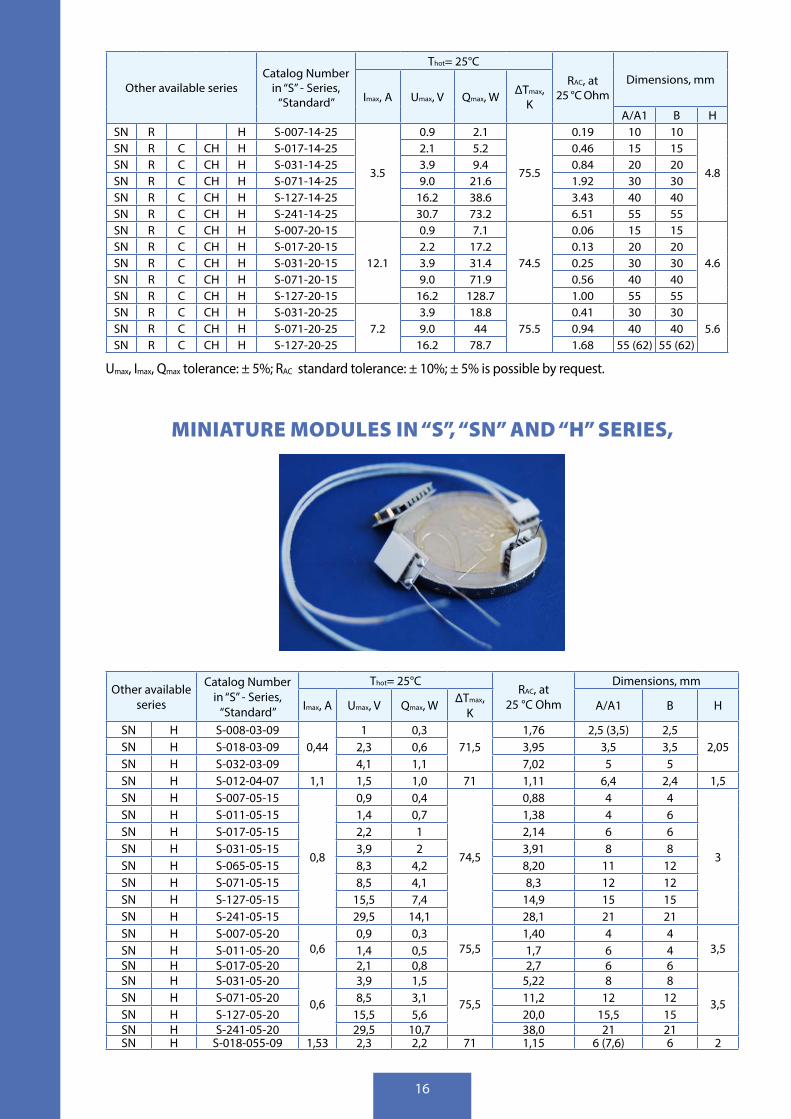
Umax, Imax, Qmax tolerance: ± 5%; RAC standard tolerance: ± 10%; ± 5% is possible by request .
MINIATURE MODULES IN “S”, “SN” AND “H” SERIES,
Other available series
Catalog Number in “S” - Series,
“Standard”
Thot= 25°СRAC, at
25 °С Ohm
Dimensions, mm
Imax, A Umax, V Qmax, W∆Tmax,
K A/А1 B H
SN H S-008-03-090,44
1 0,371,5
1,76 2,5 (3,5) 2,52,05SN H S-018-03-09 2,3 0,6 3,95 3,5 3,5
SN H S-032-03-09 4,1 1,1 7,02 5 5SN H S-012-04-07 1,1 1,5 1,0 71 1,11 6,4 2,4 1,5SN H S-007-05-15
0,8
0,9 0,4
74,5
0,88 4 4
3
SN H S-011-05-15 1,4 0,7 1,38 4 6SN H S-017-05-15 2,2 1 2,14 6 6SN H S-031-05-15 3,9 2 3,91 8 8SN H S-065-05-15 8,3 4,2 8,20 11 12SN H S-071-05-15 8,5 4,1 8,3 12 12SN H S-127-05-15 15,5 7,4 14,9 15 15SN H S-241-05-15 29,5 14,1 28,1 21 21SN H S-007-05-20
0,60,9 0,3
75,51,40 4 4
3,5SN H S-011-05-20 1,4 0,5 1,7 6 4SN H S-017-05-20 2,1 0,8 2,7 6 6SN H S-031-05-20
0,6
3,9 1,5
75,5
5,22 8 8
3,5SN H S-071-05-20 8,5 3,1 11,2 12 12SN H S-127-05-20 15,5 5,6 20,0 15,5 15SN H S-241-05-20 29,5 10,7 38,0 21 21SN H S-018-055-09 1,53 2,3 2,2 71 1,15 6 (7,6) 6 2

17
Other available series
Catalog Number in “S” - Series,
“Standard”
Thot= 25°СRAC, at
25 °С Ohm
Dimensions, mm
Imax, A Umax, V Qmax, W∆Tmax,
K A/А1 B H
SN H S-007-06-11
1,4
0,9 0,8
72,5
0,46 4 4
2,7
SN H S-017-06-11 2,2 2 1,14 6 6SN H S-018-06-11 2,2 2,1 1,25 6 6SN H S-023-06-11 2,9 2,6 1,53 8,2 6SN H S-029-06-11 3,7 3,3 1,93 10,2 6SN H S-031-06-11 3,9 3,7 1,99 8 8SN H S-068-06-11 8,7 7,8 4,53 13,2 13,2SN H S-032-06-18 0,9 3,9 2,2 74 3,6 13,9 3,9 3,3SN H S-023-065-1 2 .0 2 .9 3 .7
72,5
1 .10 6 .6 10 .6 1 .7SN H S-007-07-10 2,2 0,9 1,3 0,30 6 6
2,5
SN H S-011-07-10
2,2
1,4 2,0 0,47 6 8SN H S-017-07-10 2,2 3,0 0,73 8 8SN H S-031-07-10 3,9 5,5 1,33 10 10SN H S-065-07-10 8,3 11,5 2,79 14 15SN H S-071-07-10 8,8 11,7 3,4 15 15SN H S-127-07-10 15,7 20,9 6,1 20 20SN H S-241-07-10 29,8 39,7 11,5 30 30SN H S-007-07-15
1,5
0,9 0,9
74,5
0,45 6 6
3,0
SN H S-011-07-15 1,4 1,4 0,71 6 8SN H S-017-07-15 2,2 2,2 1,10 8 8SN H S-031-07-15 3,8 3,6 2,2 10 10SN H S-071-07-15 8,8 8,2 5,1 15 15SN H S-127-07-15 15,7 14,6 9,2 20 20SN H S-241-07-15 29,8 27,7 15,3 30 30SN H S-007-07-20
1,2
0,9 0,6
74
0,6 6,0 6,0
3,5
SN H S-011-07-20 1,4 1,0 1,0 8,0 6,0SN H S-017-07-20 2,1 1,5 1,6 8,0 8,0SN H S-031-07-20 3,8 2,8 2,8 10,0 10,0SN H S-065-07-20 8,1 6,0 5,75 14,0 15,0SN H S-071-07-20 8,8 6,3 6,2 15,0 15,0SN H S-127-07-20 15,7 11,3 11,0 20,0 20,0SN H S-241-07-20 29,8 21,4 20,9 30,0 30,0SN H S-007-07-25
1,0
0,9 0,5
75
0,8 6,0 6,0
3,9
SN H S-011-07-25 1,4 0,8 1,3 8,0 6,0SN H S-017-07-25 2,1 1,2 2,0 8,0 8,0SN H S-031-07-25 3,8 2,2 3,7 10,0 10,0SN H S-071-07-25 8,8 5,1 8,5 15,0 15,0SN H S-127-07-25 15,7 9,1 15,2 20,0 20,0SN H S-241-07-25 29,8 17,3 28,8 30,0 30,0SN H S-241-08-10 3 .0 30 .7 57 .2 72 .5 7 .72 30 30 3 .3SN H S-241-08-13 2 .3 30 .7 44 74 .5 10 .04 30 30 3 .6SN H S-007-08-15
1,9
0,9 1,2
74,5
0,35 6 6
3,8
SN H S-017-08-15 2,2 2,8 0,84 9 9SN H S-031-08-15 3,9 5,1 1,53 13 13SN H S-063-08-15 8,0 10,4 3,10 25 12SN H S-071-08-15 9,0 11,7 3,50 18 18SN H S-127-08-15 16,2 20,9 6,25 25 25SN H S-127-08-25 1,2 16,2 12,6 75,5 10,51 25 25 4,8
Imax, Umax, Qmax tolerance: ± 5%, RAC standard tolerance: ± 10%

18
“D”- SERIES. HIGH POWER DENSITY MODULES, (HPDM) Other
available series
Catalog Number Thot= 25°С
RAC, at 25 °С OhmDimensions, mm
Imax, A Umax, V Qmax, W
∆Tmax, K A1 A B H
DH D-128-10-058 .9
16 .3 89 .868
1 .39 30 34 302 .8DH D-242-10-05 30 .8 169 .7 2 .63 40 44 40
DH D-288-10-05 36 .7 201 .9 3 .13 40 44 40DH D-200-10-06 7 .6 25 .3 120 .7 71 2 .51 40 44 40 2 .54DH D-288-10-08 5 .7 36 .7 129 .2 71 4 .90 40 44 40
3 .1DH D-127-14-04 23 .2 16 .3 231 68 0 .57 40 44 40DH D-032-14-045
21,44,1 53,3
660,15 20 24 20 3,3
DH D-128-14-045 16,2 213,1 0,59 40 44 40 3,1DH D-128-14-06
14 .9
16 .3 152 .3
68
0 .82 40 44 40
3 .3
DH D-200-14-06 25 .5 236 .8 1 .29 40 44 40DH D-242-14-06 30 .8 285 .9 1 .56 52 56 52DH D-288-14-06 36 .7 340 .3 1 .86 52 56 52DH D-200-14-11
7 .825 .5 125 .4 2 .43 40 44 40
DH D-288-14-11 36 .7 180 .0 3 .56 52 56 52DH D-128-20-08 22 .4 16 .3 227 71 0 .55 55 59 55 4 .0
Imax, Umax, Qmax tolerance: ± 5%, RAC standard tolerance: ± 10% (± 5% possible by request) .
CENTER HOLE MODULES
Other available
seriesCatalog Number
Thot= 25°СRAC, at 25 °С Ohm
Dimensions, mmImax, A Umax, V Qmax, W ∆Tmax, K A B D H
R C H S-038-10-13-RH3,4
4,8 11,3 74,5 1,06 24 24 10 3,6R C H S-119-10-13-HS 15,2 35,5 74,5 3,32 30 30 4,7 3,6R C H S-125-14-11-HS 7,8 15,9 80,8 72,5 1,53 40 40 4,7 3,8R C H S-032-14-15-RH
5,54,1 15 74,5 0,56 55* 44 27 3,9
R C H S-125-14-15-HS 15,9 58,5 74,5 2,19 40 40 4,7 3,9R C H S-014-14-25-RH 3,5 1,8 4,3 75,5 0,39 26 26 14 4,7R C H S-125-14-25-HS 3,9 15,5 38,0 75,5 3,31 40 40 4,7 4,8
* Outer diameter on hot side = 55 mm . Outer diameter on cold side = 44 mm
Imax, Umax, Qmax tolerance: ± 5%, RAC standard tolerance: ± 10%; ± 5% is possible by request

19
MULTISTAGE MODULES
High performance modules for applica-tions requiring high temperature differ-ence . Because of design features these modules are used in cooling mode only .
• Recommended operation temperature: up to 90°С
• Recommended operation current: 0 .7 of Imax
• Wires: UL-approved, PVC insulated
Catalog NumberThot= 25°С
RAC, at 25 °С Ohm
Dimensions, mm
Imax, A Umax, V Qmax, W ∆Tmax, K A1 B1 A2 B2 H
2-010-06-11 1,1 0,9 0,35 92 0,66 3,9 3,9 3,2 3,2 4,22-024-06-11 1,1 2,2 0,81 92 1,58 6,1 6,1 4,1 4,1 4,62-041-04-11 0,7 3,9 0,68 89 5,00 12,0 12,0 5,0 5,0 4,02-045-10-20 2,2 4,2 1,95 90 1,90 15,2 15,2 10,9 10,9 8,02-045-10-30 1,2 4,0 1,3 90 2,90 10,9 10,9 15,2 15,2 10,0
2-046-1420-1630 4,3 3,8 5,6 85 0,76 20,0 20,0 20,0 20,0 8,82-049-10-15 2,1 3,8 3,4 85 1,58 15,0 15,0 11,5 11,5 6,62-158-10-15 3 .0 16 .2 7 .5 95 5 .00 30 30 15 15 7 .02-049-14-15 4,0 3,8 6,6 85 0,85 20,0 20,0 15,0 15,0 7,2
2-051-1420-1118 6,9 4,6 10,2 85 0,56 30,0 30,0 15,0 15,0 7,32-052-20-22 5,2 3,6 9,5 80 0,60 30,0 30,0 30,0 30,0 10,72-068-14-15 5,0 6,2 8,7 92 1,20 23,6 23,6 23,6 23,6 7,92-089-14-15 5,2 9,0 9,3 95 1,52 30,0 30,0 30,0 30,0 7,42-095-10-30 1,2 8,0 3,0 90 6,05 18,5 18,5 18,5 18,5 10,02-102-14-15 4,3 8,2 12,4 87 1,70 30,0 30,0 30,0 30,0 7,32-107-10-12 3,0 9,2 9,2 87 2,72 22,6 22,6 22,6 22,6 6,22-158-10-15 2,6 15,0 7,5 95 5,00 30,0 30,0 30,0 30,0 7,2
2-162-1420-1118 7,8 16,0 29,3 95 1,82 40,0 40,0 40,0 40,0 7,62-176-14-15 4,6 15,7 22,5 90 3,19 40,0 40,0 40,0 40,0 7,22-176-14-30 2,5 15,7 11,1 90 5,69 40,0 40,0 40,0 40,0 10,32-190-10-12 2,8 15,7 16,4 85 4,92 30,0 30,0 30,0 30,0 6,52-192-12-15 4 .0 20 .5 9 .8 90 4 .63 40 40 20 20 7 .0
2-192-1420-1118 6,7 15,6 39,3 84 2,21 40,0 40,0 40,0 40,0 8,12-192-1420-1525 5,0 16,8 30,3 96 3,11 40,0 40,0 40,0 40,0 8,1
2-196-19-14 8,5 16,1 51,6 84 1,70 40,0 40,0 40,0 40,0 7,02-198-14-11 5,7 15,8 35,2 82 2,35 40,0 40,0 40,0 40,0 6,22-199-20-15 9,3 15,6 57,1 84 1,62 62,0 62,0 62,0 62,0 8,92-199-10-13 2,4 15,7 16,5 83 5,50 30,0 30,0 30,0 30,0 6,13-052-10-15 2,1 3,7 1,4 102 1,65 15,0 15,0 15,0 15,0 9,93-054-10-13 2,6 4,1 1,52 107 1,50 12,5 12,5 14,0 14,0 9,23-055-10-15 2,0 3,8 1,5 100 1,74 15,0 15,0 15,0 15,0 9,93-070-20-25 6,5 6,5 3,0 117 0,93 36,0 36,0 36,0 36,0 16,03-087-06-11 1,2 7,5 6,8 105 5,50 11,0 11,0 11,0 11,0 8,53-119-14-15 3,9 8,0 7,5 99 2,09 30,0 30,0 30,0 30,0 10,43-119-20-14 8,0 8,2 14,9 99 0,90 44,0 44,0 44,0 44,0 12,93-229-20-15 7,4 15,5 28,6 88 1,80 62,0 62,0 62,0 62,0 12,93-229-14-15 3,6 15,7 12,5 98 3,93 40,0 40,0 40,0 40,0 10,53-231-20-14 8,3 15,3 26,8 97 1,56 62,0 62,0 62,0 62,0 13,0

20
Catalog NumberThot= 25°С
RAC, at 25 °С Ohm
Dimensions, mm
Imax, A Umax, V Qmax, W ∆Tmax, K A1 B1 A2 B2 H
3-231-20-15 8,0 16,0 29,9 101 1,80 61,0 61,0 61,0 61,0 14,53-231-10-15 1,9 15,5 6,9 104 7,22 30,0 30,0 30,0 30,0 9,54-075-20-22 6,1 6,0 1,8 122 0,87 36,3 36,3 36,3 36,3 20,34-106-14-10 5,4 7,8 3,75 125 1,32 21,7 21,7 28,3 28,3 9,34-111-10-20 1,4 7,2 1,2 110 4,70 18,0 18,0 23,9 23,9 14,64-115-14-15 3,5 7,6 2,6 121 1,95 24,0 24,0 33,0 33,0 13,84-129-10-15 1,8 8,2 1,9 113 3,83 23,0 23,0 23,0 23,0 12,54-246-20-15 6,8 15,3 14,3 105 1,97 62,0 62,0 62,0 62,0 17,04-246-14-15 3,2 15,3 6,7 109 4,22 40,0 40,0 40,0 40,0 14,0
5-131-1420-1122 5,4 7,8 1,73 125 1,40 29,7 29,7 29,7 29,7 24,35-195-20-30 4,0 13,0 2,47 125 3,10 40,0 40,0 45,0 45,0 26,0
5-195-1420-2040 3,0 13,0 1,86 129 4,20 35,0 35,0 31,0 31,0 24,45-253-10-15 1,8 15,0 1,9 120 7,80 30,0 30,0 30,0 30,0 16,25-257-10-15 1,8 15,0 2,0 123 7,90 30,0 30,0 30,0 30,0 15,46-255-14-15 3,2 15,0 1,1 125 4,20 40,0 40,0 40,0 40,0 20,8
Umax, Imax, Qmax tolerance: ± 5%; RAC standard tolerance: ± 10%; ± 5% is possible by request
THERMOELECTRIC POWER GENERATION
Thermoelectric generation bases on Seebeck’s effect, which consists in the fact that in electrical circuit consisting of different materials, connected in series, an electromotive force emerges when contacts are maintained at different temperatures .
Such circuit, composed of two different materials (semicon-ductors of n-and p-type conductivity), is called a thermo-couple or a thermoelement . The device usually consists of tens or hundreds of thermoelements, connected in series .
Traditionally, thermoelectric generators and materials are divided into high-temperature (up to 900 º C), medium-temperature (up to 550 º C) and low temperature (300º C) . Thermoelectric materials are mainly based on solid solu-tions of Si and Ge (900 º C) solid solutions PbTe and SnTe (up to 550 º C); solid solutions Bi2Te3, Sb2Te3 and Bi2Se3 (up to 300 º C) .
We observe rise of demand for low temperature power generation thermoelectric modules for use with low grade heat sources .
Basing on demand for thermoelectric modules with hot junction temperature up to 150 ºС, Crystal Ltd . manufac-tures a wide range of such modules .
P and N – dissimilar semiconductors of P- and N-nype
21
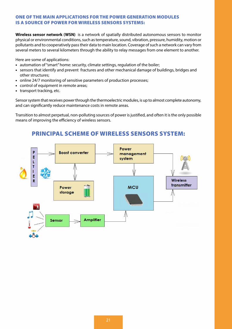
ONE OF THE MAIN APPLICATIONS FOR THE POWER GENERATION MODULES IS A SOURCE OF POWER FOR WIRELESS SENSORS SYSTEMS:
Wireless sensor network (WSN) is a network of spatially distributed autonomous sensors to monitor physical or environmental conditions, such as temperature, sound, vibration, pressure, humidity, motion or pollutants and to cooperatively pass their data to main location . Coverage of such a network can vary from several meters to several kilometers through the ability to relay messages from one element to another .
Here are some of applications: • automation of “smart” home: security, climate settings, regulation of the boiler; • sensors that identify and prevent fractures and other mechanical damage of buildings, bridges and
other structures; • online 24/7 monitoring of sensitive parameters of production processes; • control of equipment in remote areas; • transport tracking, etc .
Sensor system that receives power through the thermoelectric modules, is up to almost complete autonomy, and can significantly reduce maintenance costs in remote areas .
Transition to almost perpetual, non-polluting sources of power is justified, and often it is the only possible means of improving the efficiency of wireless sensors .
PRINCIPAL SCHEME OF WIRELESS SENSORS SYSTEM:
22
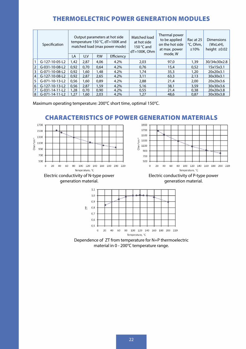
THERMOELECTRIC POWER GENERATION MODULES
Specification
Output parameters at hot side temperature 150 °C, dT=100K and matched load (max power mode)
Matched load at hot side 150 °C and
dT=100K, Ohm
Thermal power to be applied
on the hot side at max . power
mode, W
Rac at 25 °C, Ohm,
±10%
Dimensions (WxLxH),
height ±0 .02
I,A U,V P,W Efficiency 1 G-127-10-05-L2 1,42 2,87 4,06 4 .2% 2,03 97,0 1,39 30/34x30x2 .8 2 G-031-10-08-L2 0,92 0,70 0,64 4 .2% 0,76 15,4 0,52 15x15x3 .1 3 G-071-10-08-L2 0,92 1,60 1,48 4 .2% 1,74 35,3 1,20 20x20x3 .1 4 G-127-10-08-L2 0,92 2,87 2,65 4 .2% 3,11 63,3 2,13 30x30x3 .1 5 G-071-10-13-L2 0,56 1,60 0,89 4 .2% 2,88 21,4 2,00 20x20x3 .6 6 G-127-10-13-L2 0,56 2,87 1,59 4 .2% 5,16 38,1 3,59 30x30x3 .6 7 G-031-14-11-L2 1,28 0,70 0,90 4 .2% 0,55 21,4 0,38 20x20x3 .8 8 G-071-14-11-L2 1,27 1,60 2,03 4 .2% 1,27 48,6 0,87 30x30x3 .8
Maximum operating temperature: 200°C short time, optimal 150°C .
CHARACTERISTICS OF POWER GENERATION MATERIALS
Electric conductivity of N-type power generation material .
Electric conductivity of P-type power generation material .
Dependence of ZT from temperature for N+P thermoelectric material in 0 - 200°C temperature range .
23
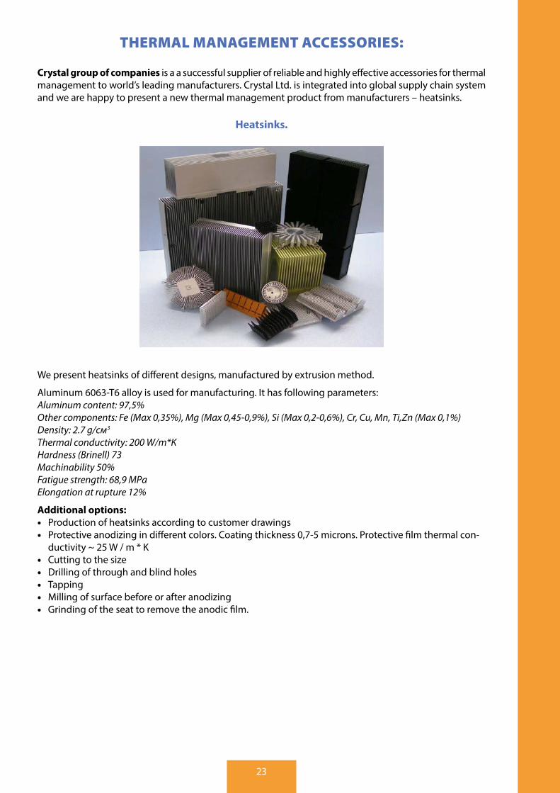
THERMAL MANAGEMENT ACCESSORIES:
Crystal group of companies is a a successful supplier of reliable and highly effective accessories for thermal management to world’s leading manufacturers . Crystal Ltd . is integrated into global supply chain system and we are happy to present a new thermal management product from manufacturers – heatsinks .
Heatsinks.
We present heatsinks of different designs, manufactured by extrusion method .
Aluminum 6063-T6 alloy is used for manufacturing . It has following parameters:Aluminum content: 97,5%Other components: Fe (Max 0,35%), Mg (Max 0,45-0,9%), Si (Max 0,2-0,6%), Сr, Cu, Mn, Ti,Zn (Max 0,1%)Density: 2.7 g/см3
Thermal conductivity: 200 W/m*КHardness (Brinell) 73Machinability 50%Fatigue strength: 68,9 МPаElongation at rupture 12%
Additional options: • Production of heatsinks according to customer drawings • Protective anodizing in different colors . Coating thickness 0,7-5 microns . Protective film thermal con-
ductivity ~ 25 W / m * K • Cutting to the size • Drilling of through and blind holes • Tapping • Milling of surface before or after anodizing • Grinding of the seat to remove the anodic film .

Crystal Ltd.
45-B Stantsionnaya St ., KOROLEV, Moscow region, 141060 RUSSIA
Tel: +7-495-664-24-31, +7-495-519-88-52, Fax: +7-495-515-40-94WEB: www,crystalltherm .com;E-mail: info@crystalltherm .com, crystalltherm@crystalltherm .com
Crystal Plant
43B, Vyazovsky lane, Bogoroditsk, Tula region, RussiaTel: +7 (4876)121620Fax: +7 (48761)65359E-mail: babkin@crystalltherm .com
R&D department
2, Institutsky st ., Mosrentgen town, Moscow,Russia Tel: +7 (495) 3395855E-mail: ponomarev@crystalltherm .com

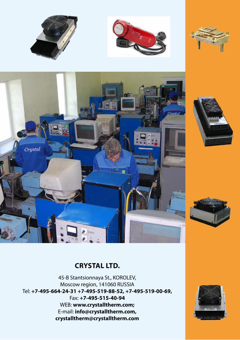
CRYSTAL LTD.
45-B Stantsionnaya St ., KOROLEV, Moscow region, 141060 RUSSIA
Tel: +7-495-664-24-31 +7-495-519-88-52, +7-495-519-00-69,Fax: +7-495-515-40-94
WEB: www.crystalltherm.com;E-mail: [email protected],