THERMODYNAMIC STUDY OF DIFFUSION … STUDY OF DIFFUSION ABSORPTION REFRIGERATION SYSTEM ... hydrogen...
12
THERMODYNAMIC STUDY OF DIFFUSION ABSORPTION REFRIGERATION SYSTEM WITH ORGANIC FLUID Mukul Kumar 1 * and R K Das 1 *Corresponding Author: Mukul Kumar, [email protected] In the recent years, the research interest on Diffusion Absorption Refrigeration (DAR) technology has increased significantly due to its ability to utilize exclusively low-grade heat to produce cooling effect. The operation of diffusion absorption refrigeration system is quiet and reliable therefore often used in hotel rooms and offices. The diffusion-absorption cycle utilizes ammonia-water- hydrogen as working fluid. In this paper, a mathematical model has been established and solved numerically. The model is based on the mass and energy conservation principles applied for every components of the DAR system, through which the working fluids flow. Equations have been developed to estimate mass flow rate, mass concentration and enthalpy of different fluids at various state points of the cycle by considering the mass balance and heat balance equations. Suitable thermodynamic relations have been used for estimating enthalpies at various points corresponding to their state properties of pressure, temperature and dryness fraction. The study showed that the COP of this refrigeration system, although not comparable with the COP of a vapour compression cycle, is encouraging, considering the fact that waste heat can be utilized for running the cycle and COP of the DAR system depends on different parameters like generator temperature, concentration of ammonia in rich solution, evaporator temperature and condenser temperature. Keywords: Ammonia-water, Bubble pump, COP, Circulation ratio, Diffusion absorption refrigeration INTRODUCTION Diffusion Absorption Refrigeration (DAR) system is one of the most fascinating field of research interest during the last few decades, especially in developing countries like India. ISSN 2278 – 0149 www.ijmerr.com Vol. 4, No. 1, January 2015 © 2015 IJMERR. All Rights Reserved Int. J. Mech. Eng. & Rob. Res. 2015 1 Department of Mechanical Engineering, Indian School of Mines, Dhanbad 826004, India. There are no moving parts in DAR System, therefore this refrigeration system has quiet, reliable and maintenance free operation. DAR system was pioneer in 1920 by Von Platen and Munters (Pongsid Srikhirin et al., 2001). The Research Paper
Transcript of THERMODYNAMIC STUDY OF DIFFUSION … STUDY OF DIFFUSION ABSORPTION REFRIGERATION SYSTEM ... hydrogen...

473
Int. J. Mech. Eng. & Rob. Res. 2015 Mukul Kumar and R K Das, 2015
THERMODYNAMIC STUDY OF DIFFUSIONABSORPTION REFRIGERATION SYSTEM
WITH ORGANIC FLUID
Mukul Kumar1* and R K Das1
*Corresponding Author: Mukul Kumar, [email protected]
In the recent years, the research interest on Diffusion Absorption Refrigeration (DAR) technologyhas increased significantly due to its ability to utilize exclusively low-grade heat to produce coolingeffect. The operation of diffusion absorption refrigeration system is quiet and reliable thereforeoften used in hotel rooms and offices. The diffusion-absorption cycle utilizes ammonia-water-hydrogen as working fluid. In this paper, a mathematical model has been established and solvednumerically. The model is based on the mass and energy conservation principles applied forevery components of the DAR system, through which the working fluids flow. Equations havebeen developed to estimate mass flow rate, mass concentration and enthalpy of different fluidsat various state points of the cycle by considering the mass balance and heat balance equations.Suitable thermodynamic relations have been used for estimating enthalpies at various pointscorresponding to their state properties of pressure, temperature and dryness fraction. The studyshowed that the COP of this refrigeration system, although not comparable with the COP of avapour compression cycle, is encouraging, considering the fact that waste heat can be utilizedfor running the cycle and COP of the DAR system depends on different parameters like generatortemperature, concentration of ammonia in rich solution, evaporator temperature and condensertemperature.
Keywords: Ammonia-water, Bubble pump, COP, Circulation ratio, Diffusion absorptionrefrigeration
INTRODUCTIONDiffusion Absorption Refrigeration (DAR)system is one of the most fascinating field ofresearch interest during the last few decades,especially in developing countries like India.
ISSN 2278 – 0149 www.ijmerr.comVol. 4, No. 1, January 2015
© 2015 IJMERR. All Rights Reserved
Int. J. Mech. Eng. & Rob. Res. 2015
1 Department of Mechanical Engineering, Indian School of Mines, Dhanbad 826004, India.
There are no moving parts in DAR System,therefore this refrigeration system has quiet,reliable and maintenance free operation. DARsystem was pioneer in 1920 by Von Platen andMunters (Pongsid Srikhirin et al., 2001). The
Research Paper

474
Int. J. Mech. Eng. & Rob. Res. 2015 Mukul Kumar and R K Das, 2015
huge advantage of DAR system is that it canoperate without electricity and thus reduces thedemand of electricity. Due to lack of movingparts DAR system has low maintenance costand because of environment-friendlyrefrigerant, it does not contribute to ozonedepletion or global-warming.
DAR cycle utilizes triple fluids namelyammonia, water and an auxiliary inert gasusually hydrogen, where ammonia is used asrefrigerant and water as absorbent. The uniquefeature of this cycle, as compared to aconventional ammonia-water absorptioncycle, is that introduction of the auxiliary inertgas plays its role to reduce the partial pressureof the refrigerant in the evaporator and allowsthe refrigerant to evaporate at low temperaturesproducing the cooling effect (Zohar and Jelinek,2007). This refrigeration system is totally heatoperated and there is no need of electrical ormechanical energy. Generally ammonia/watermixture provides cool ing at quite lowtemperatures, –10 to –30 °C, depending onthe diffusion absorption cycle conûguration butrequires moderately high driving temperatureswhich is higher than 150 °C, Although ammoniahas excellent thermo-physical properties, it istoxic, explosive, and corrosive to copper andother non-ferrous metals.
Zohar et al. (2005) developed a complexthermodynamic model that explored the DARcycle performance. They found that themaximum COP values reachable with a DARcycle can be obtained when the ammoniaconcentrations in rich and weak solutions are0.25 to 0.30 and 0.10, respectively and thatthe generator temperature is approximately200 °C. They assumed that the vapor exitingthe rectiûer was pure ammonia with no traces
of water. This is rarely true, due to the fact thatrectifler is not 100% efficient in separatingwater from ammonia.
In this paper, we investigate, by numericalsimulation, the performance of a single stagediffusion-absorption cycle operating with NH
3/
H2O mixture as working fluids and hydrogen
as auxiliary inert gas. A parametric study ofthe effect of different system parameters onthe COP is also presented by using thedeveloped model. The performance of thismixture is simulated with various generator andevaporator temperatures.
SYSTEM DESCRIPTIONSA simplified schematic diagram of the DARcycle is depicted in Figure 1. The DAR systemis similar to conventional ammonia waterabsorption refrigeration system with an inertgas usually hydrogen, diffused through thesystem to maintain a uniform system pressurethroughout the cycle. The DAR systemincludes: (i) a generator which is basically acombination of a boiler and a bubble pump,(ii) a rectifier, (iii) a condenser, (iv) anevaporator containing gas heat exchanger, (v)an absorber, and (vi) a solution heatexchanger. Geometry of the bubble pump isvery simple and it contains a cylindrical hollowtube. Application of bubble pump is to raisethe solution from the lower level to the higherone. Different operations of a DAR system areas follows:
• A generator where the rich solution ofammonia is heated increasing thetemperature of the solution,
• A bubble pump through which bubbles orvapours formed during heating of solutionrise to the separator,

475
Int. J. Mech. Eng. & Rob. Res. 2015 Mukul Kumar and R K Das, 2015
• A rectifier for condensing out the watervapour, if any, in the ammonia vapour,leaving the generator.
• A condenser for de-superheating andcondensing ammonia vapour,
• An evaporator where liquid ammonia andhydrogen gas mix and liquid ammoniaevaporates at partial pressure absorbingheat from the region to be cooled,
• An absorber where ammonia vapour isabsorbed in the weak solution of ammoniaand water, and
• A solution heat exchanger for exchangingheat between the hot weak solutionreturning from the generator and the coldrich solution going toward the generator.
Rich solution from the reservoir at 14 isheated in the solution heat exchanger by thereturn weak solution and enters the generatorat 15. When heat is supplied to the generatorat 1, bubbles of ammonia gas are producedfrom the ammonia-water mixture. Theammonia bubbles rise through the bubblepump lift tube to the separator whereammonia vapour is separated and theremaining weak ammonia-water solution(weak in ammonia) is sent to the absorber at16 through the liquid-liquid solution heatexchanger. The ammonia vapor along withsome amount of water vapour from theseparator flows through the rectifier, whereammonia and water vapour mixture is cooledand water vapour is condensed to join theweak solution at 2. Almost pure ammoniarefrigerant produced by rectification at 6enters into the condenser and condenses toliquid at 7 the total pressure of the system.The condensed ammonia flows to the
evaporator through a heat exchanger wherethe liquid ammonia is sub cooled at 9 by thecold ammonia and hydrogen mixture returningfrom the evaporator, which is mixed with theuncondensed ammonia 8 and the mixtureflows into the reservoir.
The ammonia and hydrogen gas mixtureenters the absorber coil from the bottom andflows upward while the weak solution ofammonia enters the absorber coil from the top16 and flows downward in a counter-currentarrangement. The ammonia vapor is readilyabsorbed in the weak solution and the resultingrich solution flows to the reservoir. The auxiliarygas hydrogen is not absorbed and continuesto flow to the evaporator with ammoniaresiduals at 10. The strong solution leaves thereservoir at 14 towards the generator.Hydrogen leaving the absorber is at highertemperature since it absorbs some part of heatliberated during absorption of ammonia inweak solution.
Hydrogen gas with traces of ammonia afterleaving the absorber at 10 enters theevaporator and passes through the heatexchanger. When hydrogen is allowed to mixwith the liquid ammonia at 12, the partialpressure of ammonia is reduced and thisallows the liquid ammonia to evaporate at alower temperature. The evaporation ofammonia extracts heat from the evaporator,providing refrigeration to the region to becooled. From the evaporator, the mixture ofammonia and hydrogen at 13 returns to thereservoir. In the passage this mixture absorbssome amount of heat separately from the liquidammonia coming from the condenser andhydrogen gas coming from the absorber andmoving towards the evaporator.

476
Int. J. Mech. Eng. & Rob. Res. 2015 Mukul Kumar and R K Das, 2015
One of the advantages of DAR system isthat it is self circulating system due to thegravity and density differences of the workingfluid.
It is necessary to have the following externalservices for the functioning of the cycle.
1. Supply of the heat at the generatortemperature from the external sources,which may be any source of waste heatavailable at generator temperature, likeexhaust gas from automobiles or boilers,exhaust gas from gas turbines, solar energy,etc.
2. Supply of cooling water in the condenser,in which ammonia vapour is de-superheated and condensed to liquid,liberating latent heat of liquefaction.
3. Supply of cooling water in the absorberwhere ammonia vapour is absorbed in theweak solution liberating latent heat ofliquefaction which is to be carried away bythe coolant water.
4. Supply of coolant in the rectifier. Thiscoolant may be air or water. In the rectifier(NH
3 + H
2O) vapors are cooled and since
water has higher saturation temperaturethan ammonia at any given pressure,water vapour is condensed out and almostpure ammonia proceeds to thecondenser.
NUMERICAL MODELING OFDAR SYSTEMNumerical modeling of DAR system isdeveloped to analyze the performance of the
Figure 1: Schematic Diagram of Diffusion Absorption Refrigeration System

477
Int. J. Mech. Eng. & Rob. Res. 2015 Mukul Kumar and R K Das, 2015
diffusion-absorption refrigeration cycle. Themodeling proceeds by the following steps:
• To develop mass and energy balanceequation at various component of DARsystem.
• To specify the fundamental operatingconditions like, driving heat sourcetemperature (T
gen), temperature of the cold
place (Tevp
) the temperature of thesurrounding (T
a).
• To characterize the heat and mass transferprocesses in various heat and massexchanging devices in DAR system.
Combined Generator, BubblePump, Separator and Rectifier
In the generator, the rich solution (15) is heatedby external heat source. Vapours (1) produceddue to heating rises through the bubble liftpump to the separator. Vapour (1) contain bothgasses and liquid portion of the solution.
Energy Equations: Generator energybalance: In the generator, strong solution (15)is heated by external heat source (Q
gen) and
saturated mixture of ammonia water (1)passes through the bubble pump. Thereforeenergy balance equation for generator can bewritten as:
15151111 hmhmhmQ GGLLgen ...(1)
Bubble Pump energy balance: The bubblepump acts as a heat exchanger, in which thereturning weak solution (5) absorbs someamount of heat from the rising vapours of NH
3
and H2O. Therefore,
Heat balance in the bubble pump:
552233331111 hmhmhmhmhmhm GGLLGGLL
...(2)
Rectifier Energy balance: In the rectifier,gaseous ammonia-water solution (at 3G) iscooled to produce almost pure ammoniarefrigerant (6) and condensed solution (4),which returns into separator to form weaksolution at 5. Thus energy balance equationfor rectifier gives the heat rejection from therectifier as:
446633 hmhmhmQ GGrec ...(3)
Also, heat balance for the mixing ofcondensate from the rectifier (4) and weaksolution (3
L) gives:
443355 hmhmhm LL ...(4)
Figure 2: Combined Block Diagram ofGenerator Bubble Pump Separator,
Rectifier and Heat Exchanger
Condenser
Refrigerant ammonia vapour after leaving therectifier (6) condenses in the condenser byrejecting heat into the atmosphere thus massbalance equation in the condenser.

478
Int. J. Mech. Eng. & Rob. Res. 2015 Mukul Kumar and R K Das, 2015
Energy balance equation: Ammoniarefrigerant is condensed at constant pressurein the condenser. Thus
Heat rejected in the condenser can bewritten as:
66777777 1 hmhXmhXmQ LGcon ...(5)
The liquid portion of the refrigerant (7) fromthe condenser flows through the gas heatexchanger where it is sub cooled while thevapour portion of the refrigerant by passes theheat exchanger-evaporator assembly andflows to the reservoir after mixing with the (NH
3
+ H2O) gas coming out of the gas heat
exchanger.
Expansion Chamber
Sub cooled liquid ammonia 9 meets withhydrogen gas with some residual ammoniagas in the expansion chamber (11). Thiscauses pressures of both ammonia andhydrogen to drop and mixture of NH
3 and H
2
with their respective partial pressures entersthe evaporation 12. Mass balance and energybalance for expansion chamber are presentedbelow.
Mass flow rate of ammonia vapor afterexpansion
12912 Xmmm vG
779 1 Xmm
X12
is the dryness fraction of ammonia vapourafter mixing and expansion (12)
Mass flow rate of liquid ammonia afterexpansion
12912 1 Xmmm vL ...(6)
General mass balance of ammonia at exitof expansion 12.
121212 RGL mmm ...(7)
vGL mmmm 91212 ...(8)
Energy balance equation: Energy balanceequation for sub cooled ammonia refrigeranthydrogen and ammonia residual gas leavesat expansion at 12.
9911,11 hmhmhm HHv
GGfLHH hmhmhm 1212121212, ...(9)
Evaporator Ammonia Sub Coolingand Gas Heat Exchangers
Condensed ammonia refrigerant enters intothe heat exchanger portion of the coupledevaporator and gas heat exchanger where itis sub cooled up to 9, by the cold gas mixture(NH
3 + H
2) coming out from the evaporator,
Hydrogen gas and residual ammonia mixturereleased from the absorber (10) is also cooledby the cold gas mixture from the evaporatorupto 11 before mixing with the sub cooledammonia at 9.
After mixing pressure of ammonia reducesto partial pressure in a mixture of saturatedliquid ammonia, saturated vapour ammoniaand hydrogen gas at 12. This mixture thenenters the evaporation and absorbs heat fromthe evaporation, While the liquid ammonia isfirst evaporated to saturated vapour and thenthe whole mixture is heated beyondtemperature at 12.
After leaving the evaporator the ammoniaand hydrogen gas mixture enters the gas heatexchanger where it absorbs some amount ofheat from the liquid ammonia (7L) and alsofrom mixture of hydrogen and residualammonia (10).
Mass flow rate of ammonia vapor leavingthe evaporator at 13 is given below.

479
Int. J. Mech. Eng. & Rob. Res. 2015 Mukul Kumar and R K Das, 2015
13713, 1 XmXmm vRGR ...(10)
Mass flow rate of ammonia liquid refrigerantleaving the evaporator at 13 is given below.
13713, 11 XmXmm vRLR ...(11)
Mass balance equation for ammoniarefrigerant in evaporator gas heat exchanger.Since refrigerant at 13 may consider bothsaturated liquid and saturated vapour.
13,13,13, RGRLR mmm ...(12)
139,13,13, 1 Xmmmm vRGRLR
139, Xmm vR ...(13)
Combined energy balance equation forcondense ammonia refrigerant enters at 7,residual gas mixture (ammonia and hydrogen)enters at 10 and passing through the tubemeets with sub cooled ammonia at 12,ammonia and hydrogen gas mixture leaves theevaporator at 13.
1011,7,971 TTCmhhXmQ HpHfRRevap
fRLRGRGRRhv hmhmhhm ,13,,13,,13,,13,10,11,
1213,,12,,12,,12,,12, TTCmhmhm HpHfRLRGRGR
...(14)
More the liquid evaporates while traversingthe evaporator more the NH
3 refrigerant partial
pressure in the vapor phase increases.Therefore temperature through the evaporator-gas heat exchanger increases. The evaporator-gas heat exchanger outlet temperature (T
13) is
a model input parameter of the simulation.Many factors affect the evaporation processsuch as refrigerant mass flow, NH
3 partial
pressure, temperature, absorbereffectiveness, etc. The partial pressure of NH
3
in the gas mixture is defined as:
23
3
HNH
NH
P
Pnn
n
total
part
...(15)
Absorber and Reservoir
In the Reservoir ammonia and hydrogen gasmixture leaving the evaporator at 13 anduncondensed ammonia gas from thecondenser mix with the weak solution fromthe solution heat exchanger. Ammoniavapour is readily absorbed in the weakammonia solut ion to produce strongammonia solution (14). Dur ing theabsorption processes, hydrogen gas isliberated which leaves the reservoir alongwith some amount of unabsorbed ammoniagas. Thus residual gas mixture (10)(hydrogen and unabsorbed ammonia) leavesthe reservoir and moves towards gas heatexchanger.
Energy balance equation: Heat rejected inthe absorber is given by
10,10,1414 RvHHabs hmhmhmQ
fRLRGRGRGR hmhmhXm ,13,,13,,13,,13,,8,77
161613, hmhm HH ...(16)
Heat of absorption is liberated whenammonia is absorbed in weak solutionsolution. Due to this temperature of leavingstrong solution (14) and inside gas (10)increases. Also heat is rejected from theabsorber to the atmosphere.
Solution Heat Exchanger
In the solution heat exchanger, the strongsolution is heated from state 14 to state 15 byextracting heat from the weak solution returningfrom the bubble pump.
014142216161515 hmhmhmhm ...(17)

480
Int. J. Mech. Eng. & Rob. Res. 2015 Mukul Kumar and R K Das, 2015
Relation between mole fraction and massfraction is presented below:
01.18103.17
03.17
xx
x
...(18)
Numbers of equations developed for findingthe enthalpy such that the results are obtainedin terms of refrigeration capacity, coefficientof performance, heat addition in the generator,heat rejection in the condenser and absorber.Governing equation for enthalpy of ammonia-water solution in liquid phase as well as gasphase is expressed below:
ni
mi
iiL xT
TahxTh 1,
00 ...(19)
4/
006 11, ni
mi
ii yT
TahyTh ...(20)
Temperature-pressure and mole fraction(liquid phase and gas phase) relation ispresented below.
ni
omiii p
pxaTxpT ln1, 0 ...(21)
p
pyaTypT omi
ii ln1, 4/0 ...(22)
Circulation Ratio
Circulation Ratio (CR) is defined as the ratioof the mass flow rate of the strong solutionentering the generator to the mass flow rate ofrefrigerant.
6
15
m
mf
...(23)
Cycle Performance
The performance of the DAR cycle can beexpressed in terms of COP. Performance of
the DAR system is the amount of coolingachieved by a refrigerating machine per unitheat supplied. However COP is also definedas the refrigeration rate over the rate of heataddition at the generator.
gen
evp
Q
QCOP
...(24)
RESULTS AND DISCUSSIONIn this section, the effects of variation ofgenerator temperature (T_GEN), ammoniamass concentration (ZETA) in rich solution,evaporator temperature and condensertemperature on performance parameters likeCOP, refrigeration capacity and circulationratio (ƒ) are presented.
Figures 3 and 4 present the variation ofCOP as a function of generator temperatureand ammonia concentrations in rich solution(ZETA), respectively. It can be seen that for allconcentrations, COP of the cycle is very lowat temperatures which are closer to the bubblepoint for a particular concentration. COPincrease quickly with increase in generatortemperature, reaches the peak and then
Figure 3: Effect of Generator Temp.on COP

481
Int. J. Mech. Eng. & Rob. Res. 2015 Mukul Kumar and R K Das, 2015
maximum COP occurs at generatortemperature of 100 °C, while for ZETA = 0.3,the same occurs at 160 °C of generatortemperature.
• The maximum value of COP obtained at aparticular ZETA is higher at higherconcentrations, which is justified by lowercirculation ratio at higher concentrations.The maximum COP obtained is 0.56 forZETA of 0.9 and while the same for ZETA =0.3, is only 0.18.
• For ZETA = 0.9, the maximum COP occursat generator temperature of 100 °C, whilefor ZETA = 0.3, the same occurs at 160 °Cof generator temperature.
• Variation of COP with temperature (i.e.,difference if the maximum and the minimumCOP at a particular ZETA) is higher at higherconcentrations.
• At temperatures higher than 220 °C, COPsfor all concentrations are very low andapproach towards zero.
Figure 4 exhibits the variation of COP withammonia concentration in rich solution (ZETA)at different generator temperature. The figurereveals that COP depends significantly ZETAonly at lower temperatures, while at highertemperatures, there is very little dependenceof COP on the concentration.
Figures 5 and 6 show the variation ofrefrigeration capacity as a function ofgenerator temperature and ZETA, respectively.Fig. 5 reveals that the refrigeration capacity,at a particular concentration, increases initially,reaches the peak and then starts decreasingsharply with increase in generatortemperature. On the other hand, increase of
decreases slowly with further increase ingenerator temperature.
At temperature closer to the bubble point,amount of ammonia evaporated in thegenerator is very low causing to lowerrefrigeration capacity (Figure 5). After reachingthe peak, when generator temperature isincreased, both ammonia and water areheated to higher temperatures and amount ofheat input for the mass flow rate increases,most part of which is rejected through therectifier and condenser without any significantincrease in refrigeration capacity (Figure 5).Since COP is defined as the ratio ofrefrigeration capacity and the rate heat inputin the generator, COP decreases withincrease in generator temperature. The otherrevelations from these figures are as follows:
• At a particular generator temperature, COPincreases with increase in ammoniaconcentration, but at higher temperatures,COP is less sensitive to the concentration.
• The generator temperature at which thepeak COP occurs is lower for higherconcentration (ZETA). For ZETA = 0.9, the
Figure 4: Effect of AmmoniaConcentration on COP

482
Int. J. Mech. Eng. & Rob. Res. 2015 Mukul Kumar and R K Das, 2015
ZETA at any temperature causes increase inrefrigeration capacity. The other observationsfrom these figures are as follows:
• The maximum refrigeration capacityobtained at a particular ZETA is higher forhigher concentrations, which is justified byhigher mass of refrigerant flow rate throughthe evaporator for given mass flow rate ofammonia-water solution through thegenerator at higher concentrations. Themaximum refrigeration capacity obtained is3160.7 kW for ZETA of 0.9 while the value
of the same is 743.8 kW for ZETA = 0.3.Here, it may be mentioned that the aboveperformances are obtained for a mass flowrate of 5 kg/s through the generator.
• Temperature, at which the maximumrefrigeration capacity occurs at a particularZETA, is lower for higher concentration. ForZETA = 0.9, the maximum refrigerationcapacity occurs at generator temperatureof 150 °C, while for ZETA = 0.3, the sameoccurs at 200 °C of generator temperature.
• The generator temperature, at which themaximum COP occurs, is, in general, notequal to the generator temperature, at whichthe maximum refrigeration capacity, isobtained.
CONCLUSIONA mathematical model has been developedto predict the performance of the diffusionabsorption refrigeration system for variousgenerator temperatures and concentrations ofthe refrigerant (ammonia) in the rich solutionof ammonia-water solution.
It is found that the performance of thediffusion absorption refrigeration system, ingeneral, is poor due to large amount of heatlost during cooling process in rectifier,condenser, absorber and gas heat exchanger.Although NH
3/H
2O diffusion absorption
refrigeration system can be used formaintaining temperatures below 0 °C, NH
3/
H2O mixture may not be a good potential pair
for absorption refrigeration cycles operatingwith lower generation temperatures. Theadditional advantage of this system is that thesystem can utilize heat sources like solar,geothermal, industrial waste or others.
Figure 5: Effect of GeneratorTemperature on Refrigeration Capacity
Figure 6: Effect of AmmoniaConcentration on Refrigeration Capacity
483
Int. J. Mech. Eng. & Rob. Res. 2015 Mukul Kumar and R K Das, 2015
REFERENCES1. Ben Ezzine N et al. (2010), “A Numerical
Investigation of a Diffusion-AbsorptionRefrigeration Cycle Based on R124-DMAC Mixture for Solar Cooling”,International Journal of Energy, Vol. 35,pp. 1874-1883.
2. Chen J, Kin K J and Herold K E (1996),“Performance Enhancement of aDiffusion-Absorption Refrigerator”,International Journal of Refrigeration,Vol. 19, No. 3, pp. 208-218.
3. Giuseppe Starace and Lorenzo DePascalis (2011), “An Advanced AnalyticalModel of the Diffusion AbsorptionRefrigerator Cycle”, International Journalof Refrigeration, pp. 1-8.
4. Koyfman A et al. (2003), “An ExperimentalInvestigation of Bubble PumpPerformance for Diffusion AbsorptionRefrigeration System with OrganicWorking Fluids”, Applied ThermalEngineering, Vol. 23, pp. 1881-1894.
5. Patek J and Klomfar J (1995), “SimpleFunctions for Fast Calculations ofSelected Thermo Dynamic Properties ofAmmonia-Water System”, Int. J. Refrig.,Vol. 18, pp. 228-234.
6. Pongsid Srikhirin, Satha Aphornratana
and Supachart Chungpaibulpatana(2001), Renewable and SustainableEnergy Reviews, Vol. 5, pp. 343-372.
7. Wang Q et al. (2011), “A NumericalInvestigation of a Diffusion AbsorptionRefrigerator Operating with the BinaryRefrigerant for Low TemperatureAppl ications”, Applied ThermalEngineering, Vol. 31, pp. 1763-1769.
8. Zohar A et al. (2007), “The Influence ofDiffusion Absorption Refrigeration CycleConfiguration on the Performance”,Applied Thermal Engineering, Vol. 27,pp. 2213-2219.
9. Zohar A, Jel inek M et al. (2005),“Numerical Investigation of a DiffusionAbsorption Refrigeration Cycle”,International Journal of Refrigeration,Vol. 28, pp. 515-525.
10. Zohar A, Jelinek M et al. (2007), “TheInfluence of Diffusion AbsorptionRefrigeration Cycle Configuration on thePerformance”, Applied ThermalEngineering, Vol. 27, pp. 2213-2219.
11. Zohar A, Jel inek M et al. (2009),“Performance of Diffusion AbsorptionRefrigeration Cycle with Organic WorkingFluids”, International Journal ofRefrigeration, Vol. 32, pp. 1241-1246.
484
Int. J. Mech. Eng. & Rob. Res. 2015 Mukul Kumar and R K Das, 2015
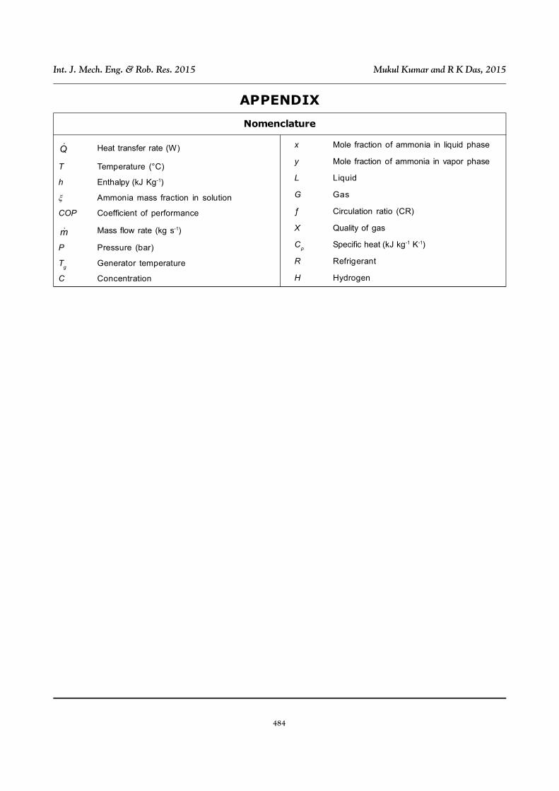
APPENDIX
Nomenclature
Q Heat transfer rate (W)
T Temperature (°C)
h Enthalpy (kJ Kg-1)
Ammonia mass fraction in solution
COP Coefficient of performance
m Mass flow rate (kg s-1)
P Pressure (bar)
Tg
Generator temperature
C Concentration
x Mole fraction of ammonia in liquid phase
y Mole fraction of ammonia in vapor phase
L Liquid
G Gas
ƒ Circulation ratio (CR)
X Quality of gas
Cp
Specific heat (kJ kg-1 K-1)
R Refrigerant
H Hydrogen