Thermodynamic Cycle Presentation
29
Thermodynamic Cycles
-
Upload
anonymous-oh1pxyx3 -
Category
Documents
-
view
220 -
download
1
Transcript of Thermodynamic Cycle Presentation

8/19/2019 Thermodynamic Cycle Presentation
http://slidepdf.com/reader/full/thermodynamic-cycle-presentation 1/29
Thermodynamic Cycles
8/19/2019 Thermodynamic Cycle Presentation
http://slidepdf.com/reader/full/thermodynamic-cycle-presentation 2/29
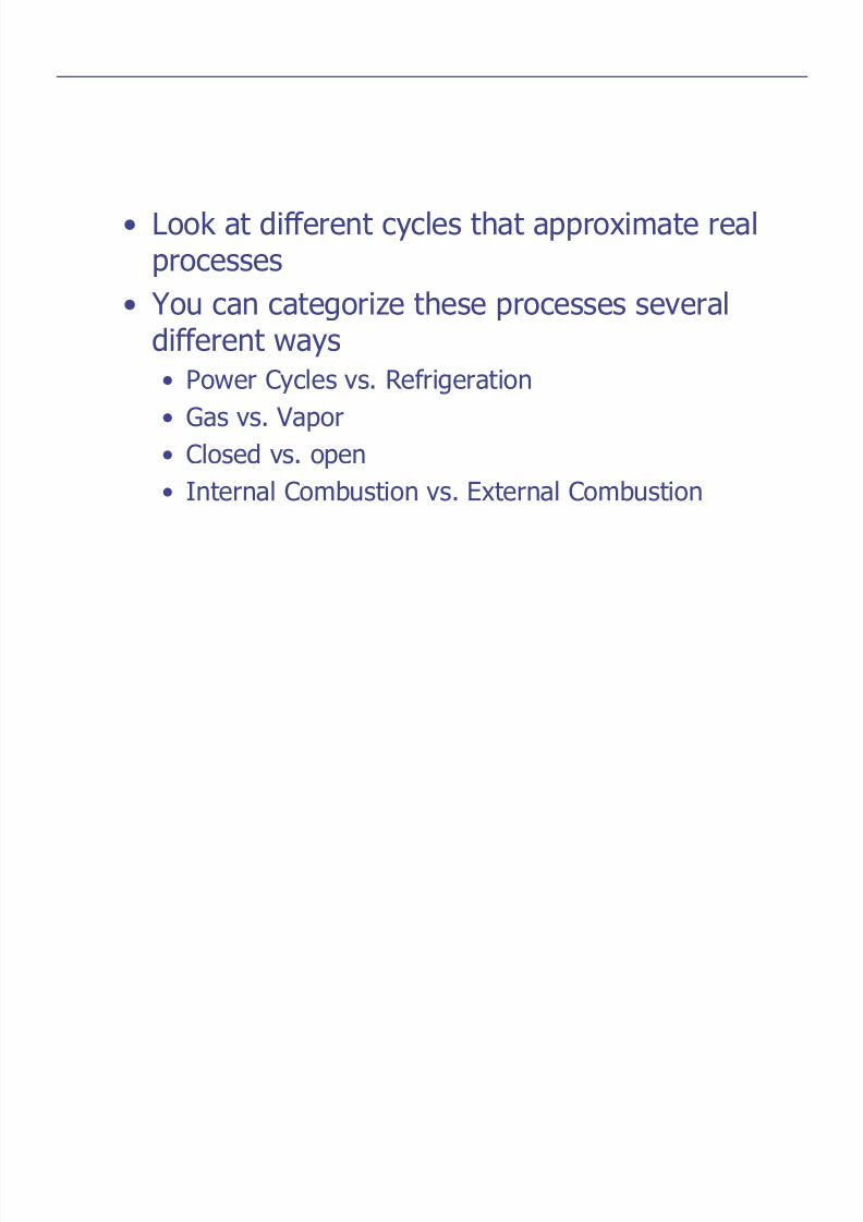
• Look at different cycles that approximate realprocesses
• You can categorize these processes several
different ways• Power Cycles vs. Refrigeration
• Gas vs. Vapor
• Closed vs. open• Internal Combustion vs. External Combustion

8/19/2019 Thermodynamic Cycle Presentation
http://slidepdf.com/reader/full/thermodynamic-cycle-presentation 3/29

8/19/2019 Thermodynamic Cycle Presentation
http://slidepdf.com/reader/full/thermodynamic-cycle-presentation 4/29

8/19/2019 Thermodynamic Cycle Presentation
http://slidepdf.com/reader/full/thermodynamic-cycle-presentation 5/29
WQ
Q-W=0 Q=W
In addition, we know that the efficiency for aCarnot Cycle is:
η th Carnot
L
H
T
T , = −
1

8/19/2019 Thermodynamic Cycle Presentation
http://slidepdf.com/reader/full/thermodynamic-cycle-presentation 6/29
Carnot Cycle is not a good model for most realprocesses
• For example• Internal combustion engine
• Gas turbine
• We need to develop a new model, thatis still ideal

8/19/2019 Thermodynamic Cycle Presentation
http://slidepdf.com/reader/full/thermodynamic-cycle-presentation 7/29
Air-Standard Assumptions
• Air continuously circulates in a closedloop and behaves as an ideal gas
• All the processes are internallyreversible
• Combustion is replaced by a heat-addition process from the outside
• Heat rejection replaces the exhaust
process
• Also assume a constant value for Cp,
evaluated at room temperature

8/19/2019 Thermodynamic Cycle Presentation
http://slidepdf.com/reader/full/thermodynamic-cycle-presentation 8/29
erminology for Reciprocating Devices
r V
V
V
V
BDC
TDC
= =max
minCompression Ratio

8/19/2019 Thermodynamic Cycle Presentation
http://slidepdf.com/reader/full/thermodynamic-cycle-presentation 9/29
Mean Effective Pressure
∫=2
1PdV W
V PW ∆=

8/19/2019 Thermodynamic Cycle Presentation
http://slidepdf.com/reader/full/thermodynamic-cycle-presentation 10/29
v
v

8/19/2019 Thermodynamic Cycle Presentation
http://slidepdf.com/reader/full/thermodynamic-cycle-presentation 11/29
1-2 Isentropic Compression
2-3 Constant Volume Heat Addition
3-4 Isentropic Expansion
4-1 Constant Volume Heat Rejection

8/19/2019 Thermodynamic Cycle Presentation
http://slidepdf.com/reader/full/thermodynamic-cycle-presentation 12/29
hermal Efficiency of the Otto Cycle
η thnet
in
net
in
in out
in
out
in
W
Q
Q
Q
Q Q
Q
Q
Q
= = = −
= −1
Apply First Law Closed System to Process 2-3, V = Constant
∫ =+=+=∆=−
3
223,23,23,
2323,23,
00 PdV W W W
U W Q
bother net
net net
Q U
Q Q mC T T
net
net in v
,
, ( )
23 23
23 3 2
=
= = −
∆

8/19/2019 Thermodynamic Cycle Presentation
http://slidepdf.com/reader/full/thermodynamic-cycle-presentation 13/29
Apply First Law Closed System to Process 4-1,V = Constant
001
441,41,41,
4141,41,
=+=+=
∆=−
∫ PdV W W W
U W Q
bother net
net net
Q U
Q Q mC T T Q mC T T mC T T
net
net out v
out v v
,
, ( )( ) ( )
41 41
41 1 4
1 4 4 1
=
= − = −= − − = −
∆

8/19/2019 Thermodynamic Cycle Presentation
http://slidepdf.com/reader/full/thermodynamic-cycle-presentation 14/29
η th Ottoout
in
v
v
mC T T
mC T T
,
( )
( )
= −
= − −
−
1
1 4 1
3 2
η th OttoT T T T
T T T
T T T
,( )( )
( / )
( / )
= − −−
= − −
−
1
11
1
4 1
3 2
1 4 1
2 3 2
Recall processes 1-2 and 3-4 are isentropic, so
1
3
4
4
3
1
2
1
1
2
T and
−−
⎟⎟ ⎠ ⎞⎜⎜
⎝ ⎛ =⎟⎟
⎠ ⎞⎜⎜
⎝ ⎛ =
k k
vvT
vv
T T
v3 = v2 and v4 = v1
T T
T T
or
T T
T T
2
1
3
4
4
1
3
2
=
=

8/19/2019 Thermodynamic Cycle Presentation
http://slidepdf.com/reader/full/thermodynamic-cycle-presentation 15/29
η th OttoT T T T
T T T
T T T
,( )( )
( / )
( / )
= − −−
= − −
−
1
11
1
4 1
3 2
1 4 1
2 3 2
1
η th Otto
T
T , = −1 1
2
Is this the same as the Carnot efficiency?

8/19/2019 Thermodynamic Cycle Presentation
http://slidepdf.com/reader/full/thermodynamic-cycle-presentation 16/29
Efficiency of the Otto Cycle vs. Carnot Cycle
• There are only two temperatures in theCarnot cycle
• Heat is added at TH
• Heat is rejected at TL
• There are four temperatures in the Otto
cycle!!• Heat is added over a range of temperatures
• Heat is rejected over a range of temperatures

8/19/2019 Thermodynamic Cycle Presentation
http://slidepdf.com/reader/full/thermodynamic-cycle-presentation 17/29
1
1
1
2
2
1 1−
−
=⎟⎟
⎠
⎞⎜⎜
⎝
⎛ =
k
k
r V
V
T
T
Since process 1-2 is isentropic,
η th Otto k r , = −
−1
1
1
η th Otto
T
T , = −1 1
2
Increasing Compression RatioIncreases the Efficiency
Typical CompressionRatios for GasolineEngines

8/19/2019 Thermodynamic Cycle Presentation
http://slidepdf.com/reader/full/thermodynamic-cycle-presentation 18/29
Why not use higher compression Ratios?
• Premature Ignition• Causes “Knock”
• Reduces the Efficiency
• Mechanically need a better design

8/19/2019 Thermodynamic Cycle Presentation
http://slidepdf.com/reader/full/thermodynamic-cycle-presentation 19/29
Diesel Engines
• No spark plug• Fuel is sprayed into hot compressed air

8/19/2019 Thermodynamic Cycle Presentation
http://slidepdf.com/reader/full/thermodynamic-cycle-presentation 20/29
State Diagrams for the Diesel Cycle

8/19/2019 Thermodynamic Cycle Presentation
http://slidepdf.com/reader/full/thermodynamic-cycle-presentation 21/29
Diesel Cycle Otto Cycle
The onlydifference
is inprocess2-3
8/19/2019 Thermodynamic Cycle Presentation
http://slidepdf.com/reader/full/thermodynamic-cycle-presentation 22/29
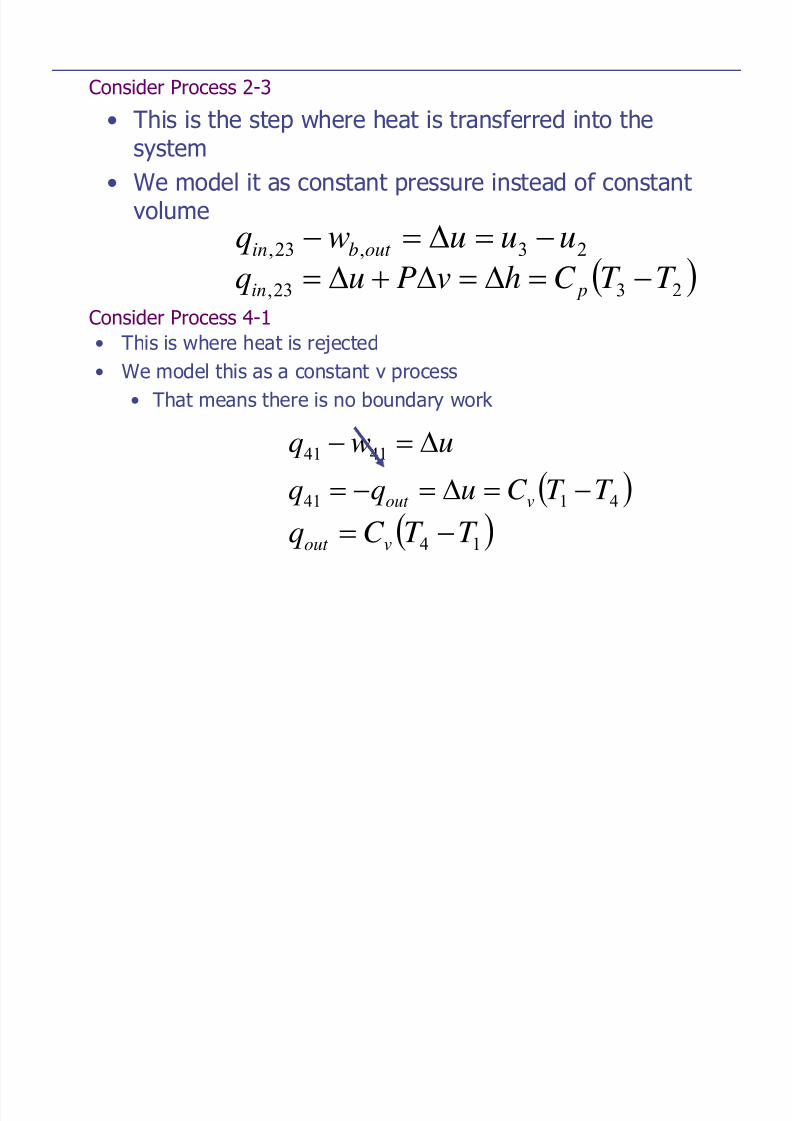
Consider Process 2-3
• This is the step where heat is transferred into thesystem
• We model it as constant pressure instead of constant
volume23,23, uuuwq out bin −=∆=−( )2323, T T C hvPuq pin −=∆=∆+∆=
Consider Process 4-1• This is where heat is rejected
• We model this as a constant v process
• That means there is no boundary work
uwq ∆=− 4141
( )4141 T T C uqq vout −=∆=−=
( )14 T T C q vout −=

8/19/2019 Thermodynamic Cycle Presentation
http://slidepdf.com/reader/full/thermodynamic-cycle-presentation 23/29
As for any heat engine…
in
out
in
net th
q
q
q
w−== 1η
( ) ( )2314 and T T C qT T C q pinvout −=−=
( )23
14,
)(1
T T C
T T C n
p
vdieselth
−
−−=
( )
( )23
141
T T k
T T
−
−−=

8/19/2019 Thermodynamic Cycle Presentation
http://slidepdf.com/reader/full/thermodynamic-cycle-presentation 24/29
Rearrange
( )
( )1
11
232
141,
−
−−=
T T kT
T T T n dieselth
PV
T
PV
T P P
T
T
V
V r c
3 3
3
2 2
2
3 2
3
2
3
2
= =
= =
where
rc is called the cutoff ratio – it’s the ratio ofthe cylinder volume before and after thecombustion process

8/19/2019 Thermodynamic Cycle Presentation
http://slidepdf.com/reader/full/thermodynamic-cycle-presentation 25/29
( )
( )1
11
2
141,
−
−−=
c
dieselth
r kT
T T T n
PV
T
PV
T V V
T
T
P
P
4 4
4
1 1
1
4 1
4
1
4
1
= =
=
where
8/19/2019 Thermodynamic Cycle Presentation
http://slidepdf.com/reader/full/thermodynamic-cycle-presentation 26/29
k k
k k
V PV P
V PV P
3344
2211 and
=
=
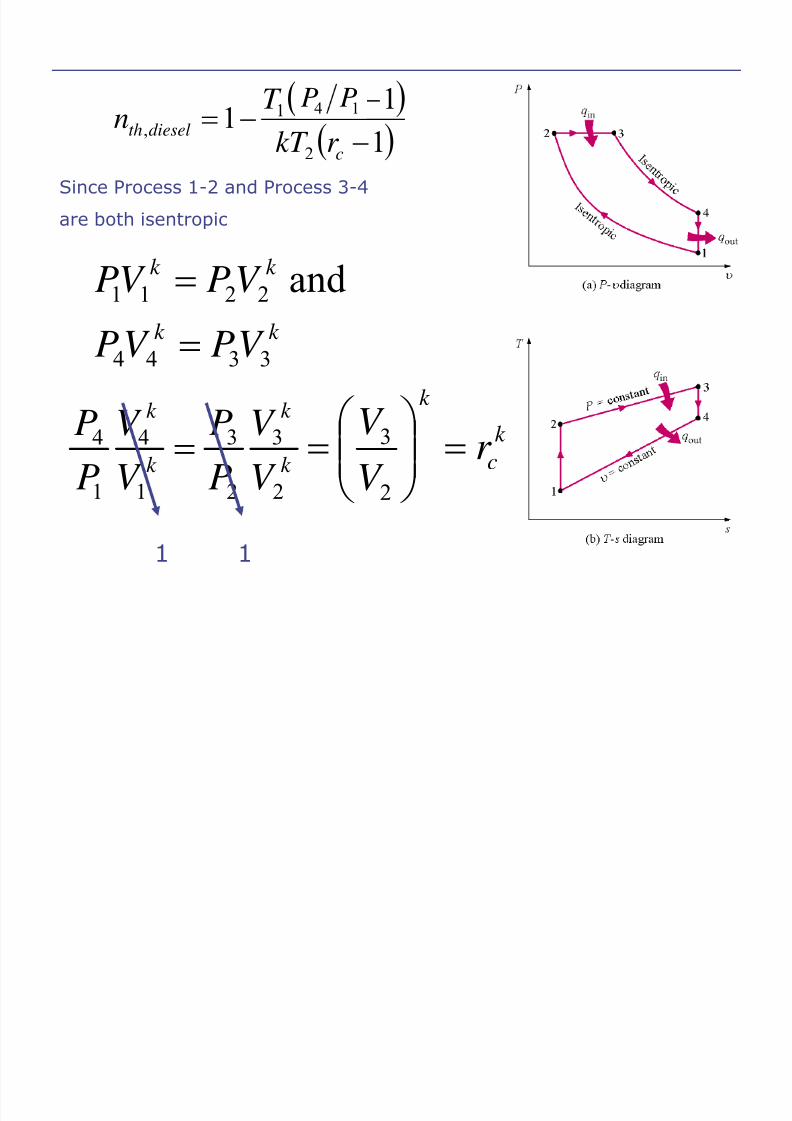
( )( )111
2
141,
−
−−=
c
dieselthr kT T T T n 14
PP
Since Process 1-2 and Process 3-4
are both isentropic
k
k
k
k
V V
PP
V V
PP
2
3
2
3
1
4
1
4=
1 1
k c
k
r V V =⎟⎟
⎠ ⎞⎜⎜
⎝ ⎛ =
2
3
8/19/2019 Thermodynamic Cycle Presentation
http://slidepdf.com/reader/full/thermodynamic-cycle-presentation 27/29
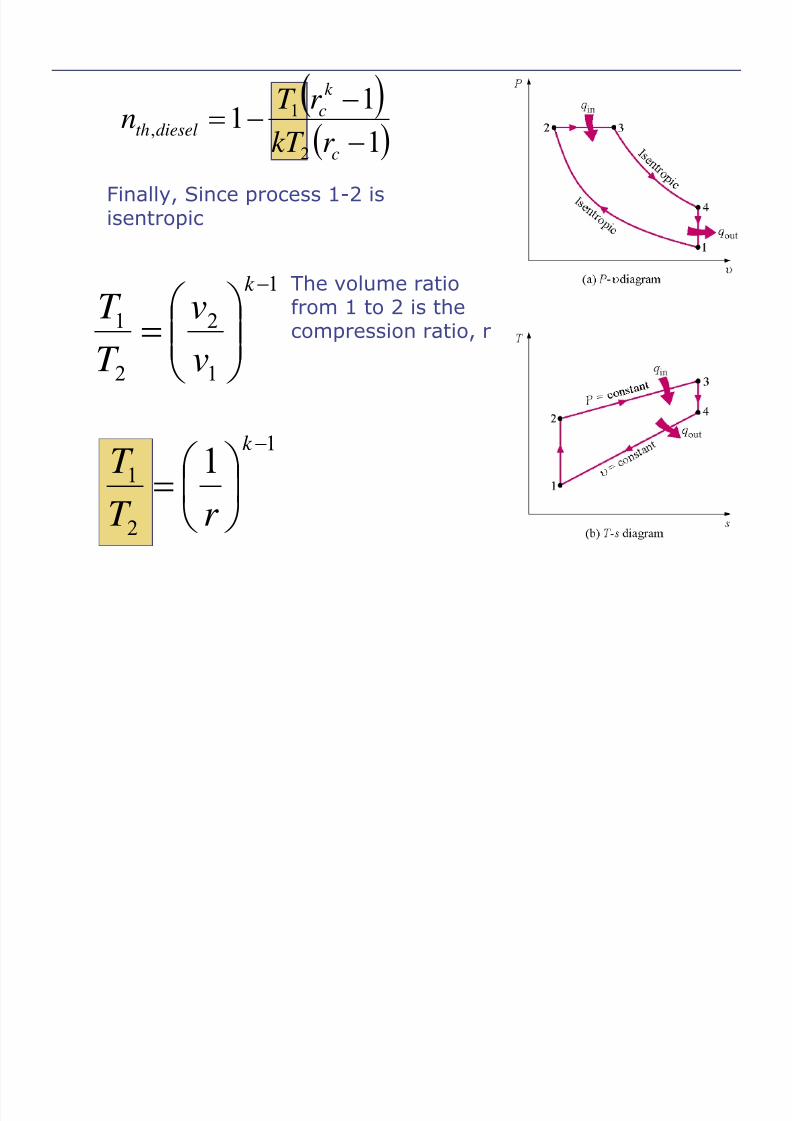
)( )111
2
1,
−
−−=
c
k
cdieselth
r kT r T n
Finally, Since process 1-2 is
isentropic
1
1
2
2
1
−
⎟⎟ ⎠
⎞⎜⎜⎝
⎛ =
k
vv
T T
The volume ratiofrom 1 to 2 is the
compression ratio, r
1
2
1 1 −
⎟ ⎠
⎞⎜⎝
⎛ =
k
r T
T

8/19/2019 Thermodynamic Cycle Presentation
http://slidepdf.com/reader/full/thermodynamic-cycle-presentation 28/29
( )⎥⎦⎤⎢
⎣⎡
−−−=
− 1111
1,
c
k
c
k dieselthr k
r r
η
k=1.4
8/19/2019 Thermodynamic Cycle Presentation
http://slidepdf.com/reader/full/thermodynamic-cycle-presentation 29/29
The efficiency of the Otto cycle is always higher than theDiesel cycle
Why use the Diesel cycle?Because you can use higher compression ratios