Thermodynamic and economic investigation of a screw ... · cogeneration applications. Fundamentals,...
60
1 Thermodynamic and economic investigation of a screw expander-based direct steam generation solar cascade Rankine cycle system using water as thermal storage fluid Jing Li 1, 3 , Pengcheng Li 2 , Guangtao Gao 1 , Gang Pei 1 *, Yuehong Su 3 , Jie Ji 1 1 Department of Thermal Science and Energy Engineering, University of Science and Technology of China, 96 Jinzhai Road ,Hefei, China 2 School of Automobile and Traffic Engineering, Hefei University of Technology,193 Tunxi Road, Hefei, China 3 Department of Architecture and Built Environment, University of Nottingham, University Park, Nottingham, NG7 2RD, UK Abstract: Solar electricity generation system (SEGS) which employs cascade steam-organic Rankine cycle (SORC) and steam screw expander (SE) is promising due to the high efficiency at moderate heat source temperature. This paper puts a special emphasis on heat storage and thermo-economic evaluation. Preferable operating temperature of the system is first clarified on the basis of SE characteristics. The temperature-dependent permissible stress of steam accumulator is modelled and the capital cost is investigated. Comparison between the direct steam generation (DSG) SEGS and an indirect one using thermal oil is made at a power capacity of 1 MW and storage of 6.5 hours. The results indicate the DSG system has both thermodynamic and economic superiorities. The hot side temperature ( H T ) of SORC generally does not exceed 250 o C to achieve an optimum solar thermal power efficiency. Given radiation of 750 W/m 2 , the maximum
Transcript of Thermodynamic and economic investigation of a screw ... · cogeneration applications. Fundamentals,...

1
Thermodynamic and economic investigation of a screw expander-based direct
steam generation solar cascade Rankine cycle system using water as thermal
storage fluid
Jing Li1, 3, Pengcheng Li2, Guangtao Gao1, Gang Pei1*, Yuehong Su3, Jie Ji1
1Department of Thermal Science and Energy Engineering, University of Science and
Technology of China, 96 Jinzhai Road ,Hefei, China
2School of Automobile and Traffic Engineering, Hefei University of Technology,193
Tunxi Road, Hefei, China
3Department of Architecture and Built Environment, University of Nottingham,
University Park, Nottingham, NG7 2RD, UK
Abstract: Solar electricity generation system (SEGS) which employs cascade
steam-organic Rankine cycle (SORC) and steam screw expander (SE) is promising
due to the high efficiency at moderate heat source temperature. This paper puts a
special emphasis on heat storage and thermo-economic evaluation. Preferable
operating temperature of the system is first clarified on the basis of SE
characteristics. The temperature-dependent permissible stress of steam accumulator
is modelled and the capital cost is investigated. Comparison between the direct
steam generation (DSG) SEGS and an indirect one using thermal oil is made at a
power capacity of 1 MW and storage of 6.5 hours. The results indicate the DSG
system has both thermodynamic and economic superiorities. The hot side
temperature ( HT ) of SORC generally does not exceed 250 oC to achieve an optimum
solar thermal power efficiency. Given radiation of 750 W/m2, the maximum

2
efficiency ( ,T m ) is 14.3% with a corresponding HT around 240 oC. The material
cost of pressure vessels is 2.55 million RMB. For the indirect system, the optimal
HT is about 230 oC and ,T m approximates to 13.2% and the estimated oil cost is
7.92 million RMB. It is recommended to adopt steam accumulators in the SE-driven
SEGS.
Keywords: solar thermal power generation; screw expander; thermal storage; steam
accumulator; part-load behavior
*Corresponding author. Tel. /Fax: +86 551 63607367. E-mail: [email protected].
1.Introduction
Screw expander (SE) is a volumetric machine used for the production of mechanical
work in the power interval from several kW to a few MW. The functional
characteristics of SE differ significantly from those of dynamic expanders (e.g.
turbines). SE has high tolerance for two-phase working fluid and the fluctuation of
heat source in a wide range of pressure, temperature and volumetric flow. It is able to
start up and shut down quickly, and has no special warm-up, less faults from
over-speeding and turning.
SE technology is promising in the low-medium temperature applications. The SE
industry is at a stage for promotion in the world, with major industrial suppliers
including Jiangxi Huadian Electric Power Co.,Ltd, Opcon Group, Kaishan Ltd.,
Denair Group, ElectraTherm, Shanghai Hanbell Precise Machinery, Heliex Power Ltd.
and QiyaoExpander Ltd. Products such as Opcon Powerbox WST (100-1600 kW) [1],
HP145/HP204 (160-500 kW) [2], SEPG (300-3000 kW) [3], LGP510-S (750-2500

3
kW) [4], KE110V-50 (60-1000 kW), 6500-FL(110 kW) [5] and Denair ORC (10-300
kW or above) [6] are available on the markets. Isentropic efficiency of 75-80% is
claimed for most products. The SE-based plants are gaining ever increasing interest as
cost-effective sustainable energy systems.
Solar electricity generation system (SEGS) holds a potential market for SE [7-10].
SEGS using steam SE avoids superheat at the expander inlet [11]. Direct steam
generation (DSG) in the parabolic trough collectors (PTCs) can be facilitated. The
system can work at lower temperature than steam turbine-driven ones without
remarkable decrement in the efficiency. The technical requirement in solar energy
collection is thus reduced. Coupling with a bottom organic Rankine cycle (ORC), the
SE does not need to experience highly off-design operation [12-14], and the SEGS
can perform better at low ambient temperature. It is especially suitable for distributed
cogeneration applications. Fundamentals, advantages and some thermodynamic
results of the SEGS using cascade steam-organic Rankine cycle (SORC) at constant
SE efficiency have been presented previously [15].
Heat storage is a key subject in solar thermal electricity generating systems. The
proposed SEGS is appreciated only if the issues related with storage can be easily
addressed. Similarly with steam turbine-driven systems, there are many alternative
materials for thermal storage of the SE-based SEGS, including molten salt, thermal oil
and water.
Molten salts were adopted for thermal energy storage in Themis solar power plant
in 1983. Salts composed of NaNO3 (wt=60%) and KNO3 (wt=40%) were chosen as

4
storage mediums of Solar Two in 1995 [16]. Molten salts acting as the heat transfer
and storage fluid were further employed in Solar Tres power plant built in 2008 [17].
After a long-term development, molten salt technology represents one of the most
flexible, efficient and cost-effective large-scale solar energy storage technologies
nowadays and is being deployed in many plants such as 280 MW Solana Generating
Station and Ivanpah concentrating solar power plant.
Thermal oil was used for storage in the first SEGS plant (SEGS I) in 1984. It was
filled into two different tanks: a hot tank, where the oil was stored after being heated
to 307 °C by the collectors, and a cold tank, where the oil was kept at about 240°C
after releasing its energy to the Rankine cycle [18-19]. This storage technology was
found to be successful for helping the plant dispatch its electricity generation during
non-sunlight periods. Another benefit was that oil could be utilized as heat transfer
fluid. Because thermal stability of commercial thermal oil could be guaranteed only
when the working temperature ranged below 395 °C, this storage concept no longer
appeared in later, more efficient SEGS plants.
Water was especially suitable to meet the requirements for buffer storage in solar
steam systems. Pros and cons of steam accumulator for thermal storage of
conventional turbine-driven SEGSs have been estimated [20-24]. Water was selected
as the storage, heat transfer and working fluid in commercial solar power plants of
Abengoa Solar's Planta Solar 10 and 20 (PS10 and PS20). In PS10, the design
temperature and pressure of the steam accumulators were 250 °C and 4 MPa,
respectively. The storage system consisted of four tanks that were sequentially

5
operated in relation to their charge status [25]. In PS20, the design values were
elevated to 300 °C and 4.5 MPa [26]. The introduction of steam accumulators
eliminated intermediate heat transfer fluid and steam generator. The storage system
could react fast to transience in radiation without complicated control strategy.
Experience in SEGSs indicates that molten salt is the best choice for thermal
storage in the high temperature application (> 400 °C) [27]. Thermal oil is attractive
in the temperature range from 300 °C to 400 °C. And both thermal oil and water are
appropriate medium at temperature below 300 °C. Notably, so far thermal storage for
SEGS is affected by the characteristics of steam turbine. Due to the technical
difficulty and short lifetime of turbine operating with wet steam, a large degree of
superheat (>100 °C) at the device inlet is favorable. This will reduce the solar power
efficiency at a given heat source temperature. For the sake of efficiency improvement
and cost-effectiveness, SEGS tends to move towards higher operating temperature
(>500 °C). As the most promising medium in such application, molten salt is currently
receiving great interest [28-33].
In case of SE, the problems associated with wet steam are overcome. It is
unnecessary to harness solar energy at temperature above 400 °C to implement
efficient power conversion. A solar electricity efficiency around 15% can be expected
with heat source of just 250 °C [15]. In this situation, steam accumulator rather than
molten salt will be a competitive method.
It is innovative to couple the steam screw expander-based SORC with DSG solar
collectors and water heat storage. Thermo-economic performance of this sort of

6
system has not been reported and it is worth examining its feasibility. Meanwhile
detailed investigation of the thermo-mechanical stress in storage vessel and the
mathematical relationship between operating temperature/pressure and consumption
of material (i.e. steel) are rare. Quantitative analysis of the capital cost of pressure
vessel working with steam for solar energy storage in the temperature range from
200 °C to 250 °C is needed and valuable.
This paper focuses on the steam SE-based solar thermal electricity system with
water as the heat transfer and storage fluid. It aims to explore the applicability of this
storage technology in the proposed SEGS. The main contributions are as follows.
(1) Advantages of the system are outlined.
(2) Mathematical model on the steam accumulator is established. Influence of key
factors on the accumulator cost is analyzed. Valuable information on the cost of
pressure vessel operating within the recommended temperature limit is
presented.
(3) Thermodynamic and economical comparisons between the SEGSs using water
and thermal oil as the storage fluids, are conducted. The superiority of the former
is clarified.
(4) Annual performance, part-load behavior and storage cost of the SE-assisted
SEGS are evaluated, giving a better understanding of the system.
2. Characteristics of screw expander
The optimum working condition of the system is rooted on the current technology of
SEs, which possess some characteristics that have significant effect on the operation

7
of SEGS, including:
(1) Allowance for flexible multi-phase expansion. SE is a kind of full-flow power
machine, which can accept not only superheated and saturated steam (or vapor in case
of organic fluid), but also wet steam and steam-liquid mixtures. Unlike the mode of
power conversion in turbines, the velocity of fluid in SEs is much lower and merely a
relatively small portion of power is facilitated by dynamic effects relevant to fluid
motion. Hence the presence of liquid droplets in the machine has little influence on its
lifetime.
(2) Low built-in expansion ratio. A small built-in expansion ratio is desirable because
it maximizes the input flow of fluid, before the high pressure port is cut off. Great
mass flow rate can diminish the effect of leakage [34]. Nevertheless, it leads to under
expansion and expulsion of the fluid at a too high pressure. Available work is thus lost
and the expander efficiency falls. There is a compromise between the manufacturing
cost and the work loss. According to the existing plants, common built-in expansion
ratio of SE is around 4.
(3) Excellent part-load behavior. Low built-in expansion ratio is not a good match for
the practical one, which usually exceeds 10 in light of the heat source and heat sink
temperatures. Fortunately, this can be compensated by the excellent part-load
behavior of SE. Many works have demonstrated this feature [35-37]. The SE can
operate efficiently to a large extent of pressure ratio ( pr ). The decline of isentropic
efficiency from the maximum is only about 10% when the operating pr increases by
three times as the built-in [38].

8
(4) Limited pressure difference. SE is positive displacement rotary machine
comprising a meshing pair of helicoid lobed rotors on parallel axes, contained in a
casing. Pressure difference across the rotors may impose heavy loads on them and
cause rotor deformation. As a result, the pressure difference at which SE can function
reliably and economically is restricted. Most commercial SEs have a maximum
operating pressure below 4.0 MPa. This constraint is similar to screw compressors
which have been widely used in low-medium pressure applications.
3. System description
Fig.1 shows the DSG solar power system using SE. Steam is generated in the PTCs.
The power conversion subsystem is the cascade SORC. Cycle I (red color) and Cycle
Ⅱ (blue color) are the steam Rankine cycle (SRC) and ORC, respectively. Cycle I
mainly consists of SE, condenser (HX1), pumps (P1, P3), steam accumulator (water
storage unit) and collectors. Cycle Ⅱ is composed of expander, condenser (HX2),
pump (P2). Regarding the properties of common organic fluids, turbine is a better
option in the ORC [15].
HX2 is the heat exchanger between the ORC fluid and the environment. Water
cooling is preferable than air cooling on account of larger temperature difference
driving the ORC and smaller negative power consumption. To support space heating
and absorption cooling, heat exchangers can be placed in parallel with HX1. HX1
serves as the evaporator for Cycle Ⅱ. Both SRC and ORC fluids undergo phase
change in HX1. The outlet temperature, pressure and quality of the fluids are affected
by the heat transfer inside. Three aspects could be considered for the feasibility of

9
HX1. First, commissioning is one practical action before the system works on the
nominal condition. In this process, auxiliary devices such as sensor, controller,
by-pass, liquid-vapor separator and reservoir are needed [39], which may shorten
commissioning time. Second, cascade Rankine cycle using mercury and steam had
been employed in historical power systems and similar heat exchangers as HX1 were
included [40], though the plants were limited probably because of high capital cost
and the obvious toxic hazard if the mercury leaked into the environment. Third,
nowadays cascade refrigeration cycle is used in low temperature applications where a
common single-refrigerant two-stage compression system gets inefficient [41]. The
internal heat exchanger plays a key role in the system and its outlet fluid in the
high-temperature circuit should not contain liquid for the proper operation of the
compressor. The experience in cascade refrigeration cycle reinforces the applicability
of HX1 in the SORC.
The operation is flexible and the system has many operating modes including:
a. Simultaneous heat collection and power conversion (Mode 1). V1, V2 and V3 are
open, and P1 and P2 work. Water is heated and vaporized in PTCs. Saturation
steam goes into the SE, exporting power during expansion. The exhaust is
condensed to saturation liquid in HX1, and is pressurized and sent back by P1 to
the PTCs. The condensation heat is used to vaporize the working fluid in the
ORC.
b. Heat storage in process (Mode 2). V3 and V4 are open and P3 runs. Solar energy
is stored in the form of water sensible heat.
10
c. Sole power conversion (Mode 3). When solar radiation is unavailable and power
is demanded, V1, V2, V5 are open. P1 and P2 run. Heat is released by water and
converted into power.
d. Simultaneous heat collection, power conversion and heat storage (or release)
(Mode 4). This mode is more complicated but also more common in practice. V1,
V2, V3 and V4 are open. P1, P2 and P3 run. The design area of PTCs is relevant
to the nominal power and capacity factor of the plant. In case of strong solar
radiation, heat collected by PTCs is partly used to generate power and the rest is
stored in the accumulator. While under weak radiation the input energy may be
not sufficient for power conversion and heat is released from the accumulator. In
both situations the SORC operates smoothly. Depending on solar radiation, the
mass flow rate through P3 is adjustable. Water leaving the solar field can be at
liquid, binary or vapor state. Superheat is prevented in a simple way.
In contrast to the conventional turbine-driven DSG solar thermal power system,
superheater is eliminated. Moreover, the technical problems associated with steam
accumulator can be more easily solved. For conventional systems the investment cost
on water storage is dominated owing to the vessel operating at high temperature and
pressure which may reach 400 °C and 10 MPa [24]. Since water is used as both
storage medium and working fluid, high discharge rate is possible and the capacity is
limited by the vessel volume. There is a decline in pressure during the discharge
process, which would lead to degradation of the turbine performance. These concerns
are eased in the present of SE because it operates at relatively lower temperature and

11
pressure, and has excellent part-load performance.
The representative two-tank heat transfer fluid (HTF) system is shown in Fig. 2.
Thermal oil is used as the HTF and heat storage medium, which is a proven
technology applied in some SEGS plants for two decades without major troubles.
Thermal oil seems to be the best HTF in regard to the operational aspect, safety and
cost [42].
A typical thermodynamic process of the cascade cycle is illustrated in Fig.3. The
numbers are linked with those in Figs.1 and 2.
4. Mathematical models
4.1. Solar energy collection efficiency
It will be shown in the following sections that collectors in both DSG and HTF
systems operate at pressure less than 4 MPa, and most commercial PTCs should be
applicable. Therefore, it is assumed in this work that the systems in comparison
employ the same kind of collectors. A type of PTC installed in the USA with up to
2700 m2 of aperture area is referenced here [43]. The performance formula of a single
PTC provided by the manufacturer is [44]:
2
( ) 0.762 0.2125 0.001672 aaPTC
b b
T TT TT
G G
(1)
where bG is beam solar radiation ; T is collector inlet temperature.
Thousands of collectors are usually adopted in SEGS, the temperature difference
between neighboring collectors is supposed to be small. To calculate the overall
efficiency for solar energy collection, it is reasonable to assume that the average
operating temperature of the collector changes continuously from one module to

12
another.
For thermal oil and water at liquid state, in order to reach an outlet temperature
outT with an inlet temperature inT , the required collector area is obtained by
( )
( )
Toutp
lPTC bTin
m C TA dT
T G
Ⅰ
(2)
where mⅠ is mass flow rate of oil or water through the collectors. For the DSG
system, it is also the mass flow rate in SRC.
Heat capacity of oil or water can be expressed by a first order approximation:
,0 0( ) ( )p pC T C T T (3)
Where ,0pC is heat capacity corresponding to a reference temperature 0T .
With 1 0.2125 / bc G , 2 0.001672 / bc G , the collector area according to Eqs. (1) -
(3) is calculated by
1 2, 1 , 2
2 2 1 1 2
( )( )ln ( )ln
( )out a in a
l p a p ab in a out a
m T T T TA C C
c G T T T T
Ⅰ(4)
Eq.(4) is the analytic solution to the formula of integration of Eq.(2). 1c and 2c
are two defined intermediate parameters. 1 and 2 are the arithmetical solutions of
Eq. (5)( 1 20, 0 ).
21 20.762 0c c (5)
, ,0 0( )p a p aC C T T (6)
1 and 2 can be determined once solar radiation is known since Eq.(5) is a
common quadratic function.
Collector efficiency in liquid phase region is calculated by
,l
PTC lb l
m h
G A (7)

13
Eq. (7) is adequate to calculate the solar energy collection efficiency of HTF system.
For DSG system, the solar field contains steam-liquid mixture. Overall collector
efficiency is calculated by Eq. (8)
, ,
( )
l
l bPTC
l bb l b
PTC PTC b
h hQ
h hG A A
(8)
where lh and bh are the enthalpy increments of water in liquid phase and
binary phase regions. ,PTC b can be easily calculated since the temperature is
constant.
4.2. Power conversion efficiency
4.2.1. Expanders
The work generated by SE or turbine is defined as Eq. (9) or Eq. (10):
1 2 1 2( ) ( )SE s SEW m h h m h h Ⅰ Ⅰ (9)
П 5 6 П 5 6( ) ( )T s TW m h h m h h (10)
4.2.2. Heat exchanger
Heat balance in HX1 is expressed by
)()( 8532 hhmhhm ⅡⅠ (11)
4.2.3. Pumps
The work required by pump is expressed by
1 4 3 4 3( ) ( ) /p s pW m h h m h h Ⅰ Ⅰ (12)
2 П 8 7 П 8 7( ) ( ) /p s pW m h h m h h (13)
The pressure drop through the collectors, heat exchangers and pipes are neglected.
Flow resistance in the PTCs is supposed to have limited effect on the net power

14
output of the system. For example, if the design pressure at the SE inlet is 4.0 MPa
and the pressure loss in the PTCs is 0.5 MPa, then the outlet pressure of P1 will just
need to increase from 4.0 to 4.5 MPa. The relative increment in the power
consumption of P1 is about 12.5%. Because the pump power is very small in
comparison with the expander output (about 1.5% of the latter) [15], the influence of
the pressure drop in the PTCs will be slight.
4.2.4. Thermal efficiency of the cascade Rankine cycle
Heat-to-power conversion efficiency of the SORC is
1 4( )net
SORC
W
m h h
Ⅰ
(14)
1 2net SE T g p pW W W W W (15)
Analogously, for the SRC and ORC,
1
1 4( )
SE g pSRC
W W
m h h
Ⅰ
(16)
2
5 8( )
T g pORC
W W
m h h
Ⅱ
(17)
4.3. Solar thermal power generation efficiency
Thermal efficiency ( T ) of the proposed system indicates how effectively solar
radiation is converted into electricity.
AG
W
b
netPTCSORCT
(18)
4.4. Part-load behavior of SE
Built-in volume ratio of SE ( ,v br ) is defined as
,
,
,
out b
v b
in b
vr
v (19)

15
The operating pressure ratio ( pr ) is defined as
inp
out
pr
p (20)
,v br and pr are the known parameters normally available in the literature [45].
There are four types of losses in SE operation [38]:
(i) Loss due to mismatch of the operating pressure ratio to the built-in ,p br ;
(ii) Fluid leakage loss;
(iii) Loss due to thermodynamic irreversibility;
(iv) Mechanical friction loss from the rotating shaft.
For each stage of the work loss, an efficiency term can be specified to account
for it. They are theoretical, leakage, thermodynamic and mechanical efficiencies for
(i)-(iv), respectively. The actual overall isentropic efficiency can thus be defined as:
os Th L TM M Th D M (21)
where D L TM (22)
M is determined by the characteristic of SE, and it has a constant value for a specific
SE. By definition, the theoretical efficiency is given as [38]:
1, ,
(1 )/
(1 ) ( 1)(1 / )
[1 ]
v b v b pTDTh
TI p
r r rW
W r
(23)
where TDW and TIW are theoretical diagram power and theoretical isentropic power
respectively. is the isentropic index. It depends on the working fluid and its state
and is 1.13 for dry saturated steam. ‘Pseudo-polytropic’ index could replace to give
the actual expansion path of fluid when it is correlated against the specified inlet and
outlet conditions [45].

16
The thermodynamic work output can be estimated by summing the shaft work output
and the frictional work, i.e.
TM S FW W W (24)
The actual TMW could be well lower than the polytropic work output attributed to the
irreversibility losses of fluid expansion and admission, blowdown exhaust and other
leakage losses. FW is a direct function of the shaft speed N . It is generally
assumed to be unchanged if the rotation speed is held constant. Mechanical friction is
insignificant as compared with the mismatching of pr , leakage and presence of
thermodynamic irreversibilities [45].
The diagram efficiency is given by the ratio of the thermodynamic work to the
theoretical diagram work, i.e.
1, ,(1 )
(1 )1
s FTMD
TD v b v bt su s
p
W WW
W r rm p
r
(25)
The definition of diagram efficiency includes the effect of leakage and
thermodynamic irreversibility. The leakage mass flow rate in an expander can be
estimated using the ideal-gas choked flow model with a given leakage flow area [46].
Therefore, it is expected that the behavior of diagram efficiency is similar to that in
the conventional turbomachines. Increment in ,v br has a negative effect on the
diagram efficiency, but the efficiency variation is quite slight at high pr [47].
Peak isentropic efficiency ( ,os p ) can be achieved when ,Th p is 1.
, ,os p Th p D M (26)
Combine Eqs. (21), (23) and (26), os can be estimated as:

17
1, ,
, , 1 /,
(1 ) ( 1)(1 / )
(1 )
v b v b pDos os p Th os p
D p p
r r r
r
(27)
According to Eq. (27), the actual SE efficiency is affected by the operating pr , ,os p ,
,v br , working fluid and state.
4.5. Cost of heat storage units
The thermodynamic performance comparison between the DSG and HTF systems can
be made by the above models. Economic performance is important and a
confrontation can be also conducted. According to Figs.1 and 2, costs of the heat
storage units and collectors are the remarkable difference between the two types of
systems. The collector cost can be figured out by the overall areas, which is related to
the system power efficiency. Given a plant capacity, the cost of thermal energy
storage (e.g. 6.5 hours) depends upon many factors involving the size of vessel,
materials of construction, shape, welding requirements and additional custom
standards. Taking into account all these factors will make the calculation difficult.
However, like large heat exchangers whose cost is mainly contributed by the
exchanger area and hence total amount of materials in use [48-49], large pressure
vessels have the cost in approximate proportion to the vessel weight [50]. In particular,
comparison between thermal storages using water and oil for the SE-based SEGS is
one key issue in this work. The two fashions of storage units have similar cost related
to indirect equipment expense, direct field labor for manufacture and installation, etc.
The water-type storage is distinguishable from the other in view of the need of more
steel for the vessel and the avoidance of expensive oil. Based on the above
consideration, this section pays attention to the cost of materials for heat storage.
18
The material cost of steam accumulator is determined by
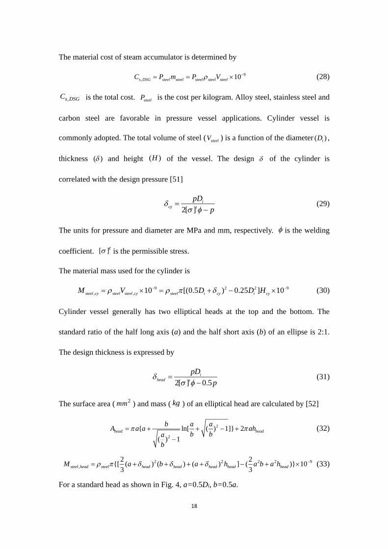
9, 10s DSG steel steel steel steel steelC P m P V (28)
,s DSGC is the total cost. steelP is the cost per kilogram. Alloy steel, stainless steel and
carbon steel are favorable in pressure vessel applications. Cylinder vessel is
commonly adopted. The total volume of steel ( steelV ) is a function of the diameter ( )iD ,
thickness ( ) and height ( )H of the vessel. The design of the cylinder is
correlated with the design pressure [51]
2[ ]i
cy t
pD
p
(29)
The units for pressure and diameter are MPa and mm, respectively. is the welding
coefficient. [ ]t is the permissible stress.
The material mass used for the cylinder is
9 2 2 9
, , 10 [(0.5 ) 0.25 ] 10steel cy steel steel cy steel i cy i cyM V D D H (30)
Cylinder vessel generally has two elliptical heads at the top and the bottom. The
standard ratio of the half long axis (a) and the half short axis (b) of an ellipse is 2:1.
The design thickness is expressed by
2[ ] 0.5i
head t
pD
p
(31)
The surface area ( 2mm ) and mass ( kg ) of an elliptical head are calculated by [52]
2
2
{ ln[ ( ) 1]} 2
( ) 1head head
b a aA a a ah
b ba
b
(32)
2 2 2 2 9,
2 2{[ ( ) ( ) ( ) ] ( )} 10
3 3steel head steel head head head head headM a b a h a b a h (33)
For a standard head as shown in Fig. 4, a=0.5Di, b=0.5a.

19
20.345head i i headA D D h (34)
22 9
,
5 2[ ( ) ] 10
3 6 3i
steel head steel head i head head i head head
DM D D h (35)
headh can be 25, 40 and 50 mm as regulated by the standard [53].
The total mass of material used for the vessel is approximated by
, ,2steel steel cy steel headM M M (36)
The design pressure p is the sum of the saturation pressure ( sp ) of water at the
design temperature and the static pressure ( gp ) caused by gravity. The vessel can be
laid up in two ways (as shown in Fig. 5) determined by the axis of symmetry of the
cylinder. For a vessel of vertical axis, the design pressure is expressed by
9( 2 2 ) 10s g s w cy headp p p p g H b h (37)
For a vessel of horizontal axis, the design pressure is expressed by
910s g s w ip p p p gD (38)
The determination of permissible stress is not at discretion. There are strict technical
standards. Permissible stresses for six types of materials are listed in Table 1, which is
guideline for the vessel design.
For the thermal oil storage unit,
, , ,s HTF s steel s oilC C C (39)
,s oil oil oil oilC P V (40)
,
3600 H netoil oil
SORC p oil
t WV
C T
(41)
Ht is storage time in hour. ,p oilC is the heat capacity of the oil. T is the
temperature drop from the hot to the cold tank.
5. Results and discussion

20
In this section, optimization of the SEGSs using water (direct system) and oil (indirect
system) as heat transfer medium in the PTCs is first implemented at certain solar
radiation and environment temperature. Mode 1 in Section 3 is exemplified. The
objective function is solar electricity efficiency. The variables are SRC evaporation
temperature ( 1T ) and ORC evaporation temperature ( 5T ), which may be deemed as
two dimensional arrays [ 1T , 5T ]. After finding out the optimum [ 1,opT , 5,opT ] on the
given boundary conditions, cost-effectiveness of the thermal storage unit is
investigated. Mass of steel at the preferable operation temperature is subsequently
estimated in consideration of parametric distributions and arrangements of the vessels.
Finally, cost comparison between DSG and HTF systems is conducted.
Some specific parameters and their values are listed in Table 2. R245fa is chosen
for the ORC. Subcritical cycles are considered for both ORC and SRC. The ORC
turbine has a constant efficiency.
5.1. The optimum hot side temperature ( ,H opT )
5.1.1. ,H opT at 750 W/m2
Fig. 6 shows the heat collection efficiencies of direct and indirect systems and the
cascade cycle efficiency varying with the hot side temperature HT (i.e. temperature
at the SE inlet, 1T ) under the beam solar radiation of 750 W/m2. The ORC
evaporation temperature varies with HT in order to promote the heat-to-power
conversion efficiency. Water prior to the SE remains at saturation vapor state. The
temperature difference between thermal oil inlet and outlet is 50 oC. Temperature
interval of neighboring points of HT in calculation is 10oC. The collector efficiencies

21
for both systems decline approximately linearly with the increment in HT . The heat
carried away by water is divided into two parts: latent heat and sensible heat. Due to
the heat transfer irreversibility the average operating temperature of thermal oil is
larger than the water’s. Solar energy collection of the DSG system is more efficient by
4%-10%. This superiority gets more appreciable as HT increases.
The power conversion efficiency of SORC first climbs when HT rises, and then
approaches to the peak point at HT around 320 oC, and drops with further
temperature increment. It is not a monotonically increasing function of the hot side
temperature, which is inconsistent with the behavior of a Rankine cycle of constant
expander efficiency. There are two reasons behind this phenomenon. For subcritical
ORC with working fluid of R245fa, the efficiency goes up insignificantly or even falls
down as the evaporation temperature ( 5T ) moves close to its critical temperature (154
oC), attributed to the decrement in the fluid’s equivalent hot side temperature [55].
The other reason is that SE will go through highly off-design operation as HT
increases due to the small built-in volume ratio. The power conversion in the SRC
suffers from the degraded SE performance.
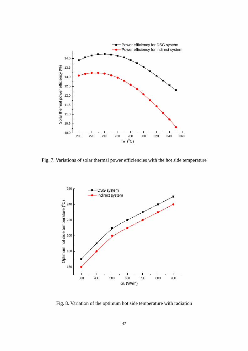
The solar thermal electricity efficiencies of the DSG and indirect systems varying
with HT are depicted in Fig. 7. Both curves have parabola-like shapes, and open
downward. At each HT , the DSG system has a higher efficiency than the indirect one.
The maximum efficiency is 14.3% and 13.2% for the former and the latter. And the
corresponding optimum TH is about 240 oC and 230 oC. Given the solar radiation and
ambient temperature, it can be deduced that the optimum TH of the DSG system

22
surpasses that of the indirect system. According to Eq. (18), the derivative of solar
electricity efficiency with respect to HT is expressed as
PTC SORCTSORC PTC
H H H
d dd
dT dT dT
(42)
When HT is lower than 320 oC, 0SORC
H
d
dT
and 0PTC
H
d
dT
. For common solar
collectors, PTC and PTC
H
d
dT
(absolute value) are monotonically decreasing and
increasing functions of HT , respectively. Given HT , the expression for DSG system
differs from the indirect system’s in the collector efficiency ( ,PTC DSG and ,PTC HTF ).
The relationship between them is
, ,( ) ( )PTC HTF H PTC DSG HT T , 0 (43)
For both systems, HT at the peak efficiency points ( ,H DSG opT and ,H HTF opT ) shall
fulfill
0T
H
d
dT
(44)
,
,
,( ) 0
H H DSG op
PTC DSG SORCSORC PTC DSG
H H T T
d d
dT dT
(45)
,
,
,( ) 0
H H HTF op
PTC HTF SORCSORC PTC HTF
H H T T
d d
dT dT
(46)
Because
, ( )PTC DSG HT > , ( )PTC HTF HT (47)
, ,PTC DSG PTC HTF
H H
d d
dT dT
(48)
Therefore

23
,
,
,( ) 0
H H DSG op
PTC HTF SORCSORC PTC HTF
H H T T
d d
dT dT
(49)
,PTC HTF
H
d
dT
and ,PTC HTF are monotonic functions of HT . Combining (46) and (49),
,H DSG opT > ,H HTF opT (50)
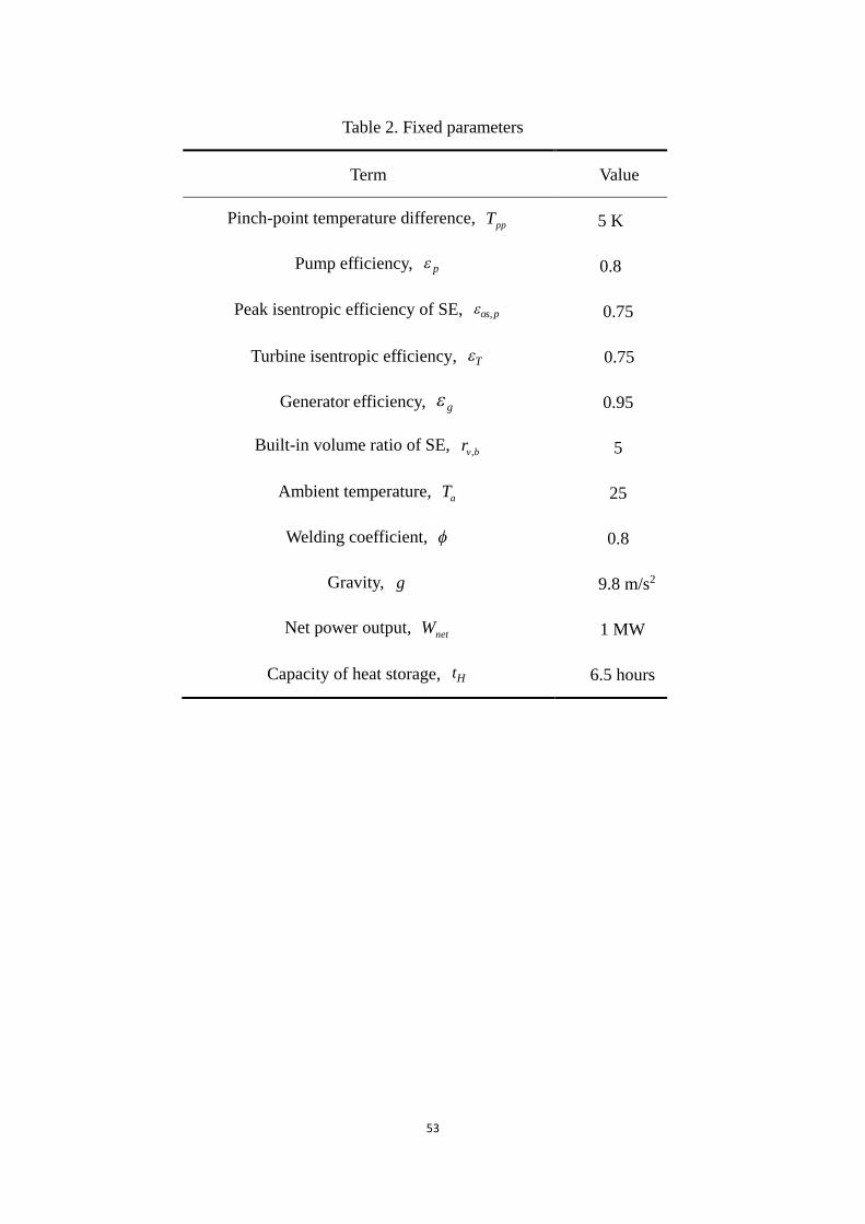
5.1.2. ,H opT varying with solar radiation
The influence of solar radiation on ,H opT is illustrated by Fig. 8. The corresponding
solar electricity efficiency variations are exhibited in Fig. 9. In the normal radiation
ranges from 600 W/m2 to 900 W/m2, ,H opT of the DSG system varies from 220 oC to
250 oC. It is comparatively low for the thermal oil-connected system. The maximum
T ascends as the radiation turns stronger, though the increment becomes less
significant. The efficiency difference between the DSG and indirect systems is about
0.9-1.5%, and the largest occurs at the lowest radiation. The detailed parameters on
the optimum conditions at three levels of radiation are posted in Tables 3 and 4. The
corresponding thermodynamic state points are marked in Figs.1 and 2.
5.1.3. Annual ,H opT in six areas
Solar radiation fluctuates from time to time in practice. The optimum operation of the
SEGS is linked with the local meteorology. The recommended ,H opT at the design
condition in six areas of rich solar energy resource is provided in Table 5. Hourly
weather data in a typical year are used [56]. ,H opT changes with the location and
ranges from 200 oC to 240 oC. In other areas of poorer solar energy, ,H opT is expected
to be lower. The relative increment of annual power output of the DSG system by that
on the use of the indirect system is around 10%.

24
The above analysis indicates that owing to the compromise among solar energy
collection, temperature difference driving the cycle and irreversibility of SE, the
preferable ,H opT shall go below 250 oC. It is a desirable thermodynamic result since
common SEs operate at pressure up to 4 MPa and water can be selected for heat
storage.
5.2. Parametric effect on steam accumulators in the DSG system
Q345R is exemplified. It is currently the most widely used material for
manufacturing vessels and boilers in China. It has been permitted in ASME Code
Case 2642 for the fabrication of pressure vessels without concern on the low stress
conditions [57]. It is a typical low alloy steel, originated from three old steel grades of
16MnR, 16Mng and 19Mng. It has good mechanical properties of low phosphorus
and sulfur contents. Small amounts of trace elements are allowed to be added to
improve smelting and rolling processes. The regulated quality of components for
Q345R is listed in Table 6 [58]. Design thickness of vessel made of Q345R on
different conditions of temperature, pressure and diameter is indexed in Table 7.
Based on the thermodynamic results in Section 5.1, a design temperature of 250
oC for the steam accumulator is selected. The saturation pressure of water at this
temperature is 3.98 MPa. The practical temperature/pressure could be lower than the
design. The reference radiation is 750 W/m2. The total mass of water in use varies
with the temperature range of operation. A larger temperature drop of water during
heat discharge will lead to a smaller accumulator. But as the temperature descends, the
supply pressure for SE will be diminished, thus affecting the power conversion. The

25
curve in Fig. 7 shows that the DSG system efficiency almost keeps constant when HT
stays within the interval of (230 oC, 250 oC). Therefore, the temperature drop is
assumed to be 20 oC in the heat release process. Given cascade cycle efficiency ( SORC )
of 23.5% at 240 oC and 6.5 h storage, a total volume of 1204 m3 of water for storage is
required, as calculated in a similar way by Eq.(41).
5.2.1. Single pressure vessel
Fig. 10 shows material consumption ( steelM ) and vessel design pressure ( p ) varying
with the diameter ( iD ) for the vertical vessel. steelM first decreases drastically as iD
increases, reaching a minimum value of about 861.3 tons at iD of 4600 mm and
then climbs gradually with further increment in iD . The decline of steelM is
attributed to a lower p when the vessel is enlarged. The vessel volume is constant
and the height ( cyH ) is linearly inversely proportional to the square of iD . So the
increment of iD leads to reduced cyH and p . The influence of iD on p becomes
unnoticeable in the low range of cyH . At iD =5000 mm, cyH is about 61 m and the
pressure due to gravity is about 0.6 MPa, which is around one-seventh of the
saturation pressure of water at 250 oC. In this situation, iD has limited effect on the
design pressure but much more appreciable one on the mass of Q345R for the heads.
When iD changes from 5000 mm to 9000 mm, the overall head mass ( ,2 steel headM )
goes up from 43.0 tons to 229.6 tons.
The effect of iD on steelM and cyH in case of horizontal vessel is graphed by
Fig. 11. cyH is actually the vessel length rather than the height so the design pressure
is a weak function of iD . Unlike that of vertical vessel, steelM rises in a monotonic

26
fashion. In light of Eq. (29), given p and the permissible stress, cy is almost
proportional to iD . Because 2, / (0.25 )steel cy steel i cy cy steel i cy vessel iM D H D V D ,
so ,steel cyM /cy iD and nearly unvaried ,steel cyM can be expected. Meanwhile,
higher iD is accompanied by larger ,steel headM , resulting in a monotonically
increasing steelM with increment in iD . Several sudden growths in steelM are
observed at iD around 1100, 2300, 3500, 5400 and 7800 mm. They are caused by
the non-continuous regulated permissible stress of Q345R. The stress may de-escalate
abruptly as wall thickness increases. At each iD , steelM of the horizontal vessel gets
below the vertical’s. When iD =4600 mm, the former is 735.5 tons, nearly 14.6%
lower than the latter. The difference turns larger at smaller iD .
Figs. 10 and 11 indicate iD of no more than 5000 mm is material-saving. In
particular, the horizontal vessel always benefits from the decrement in iD in terms of
the consumption of Q345R. However, cyH could be extremely high at low iD . It is
about 72 m at iD =4600 mm. There will be great difficulty in fabrication and
transportation of such a vessel.
5.2.2. Vessels in parallel
To solve the problem of unusual cyH , two or more vessels can be employed
concurrently. Figs. 12 and 13 present the relationship between steelM and the number
of vessels ( N ) in use. The vessels of a given number are of the same dimension and
design pressure, and work in parallel with each other. For all cases, cyH is fixed at 25
m. steelM is the total mass of the vessels. Obviously, steelM together with iD drops
as more vessels are utilized. The sudden decrements are facilitated by the hopping
27
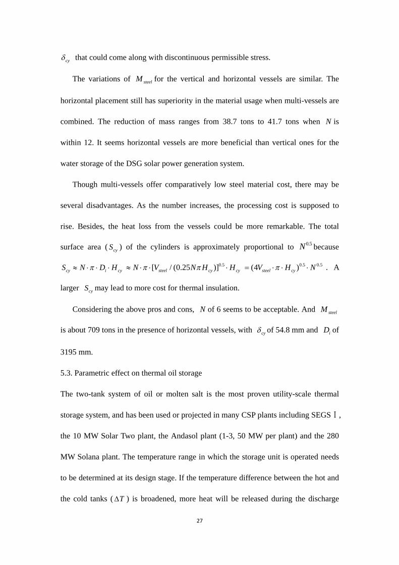
cy that could come along with discontinuous permissible stress.
The variations of steelM for the vertical and horizontal vessels are similar. The
horizontal placement still has superiority in the material usage when multi-vessels are
combined. The reduction of mass ranges from 38.7 tons to 41.7 tons when N is
within 12. It seems horizontal vessels are more beneficial than vertical ones for the
water storage of the DSG solar power generation system.
Though multi-vessels offer comparatively low steel material cost, there may be
several disadvantages. As the number increases, the processing cost is supposed to
rise. Besides, the heat loss from the vessels could be more remarkable. The total
surface area ( cyS ) of the cylinders is approximately proportional to0.5N because
cy i cyS N D H 0.5[ / (0.25 )]steel cy cyN V N H H 0.5 0.5(4 )steel cyV H N . A
larger cyS may lead to more cost for thermal insulation.
Considering the above pros and cons, N of 6 seems to be acceptable. And steelM
is about 709 tons in the presence of horizontal vessels, with cy of 54.8 mm and iD of
3195 mm.
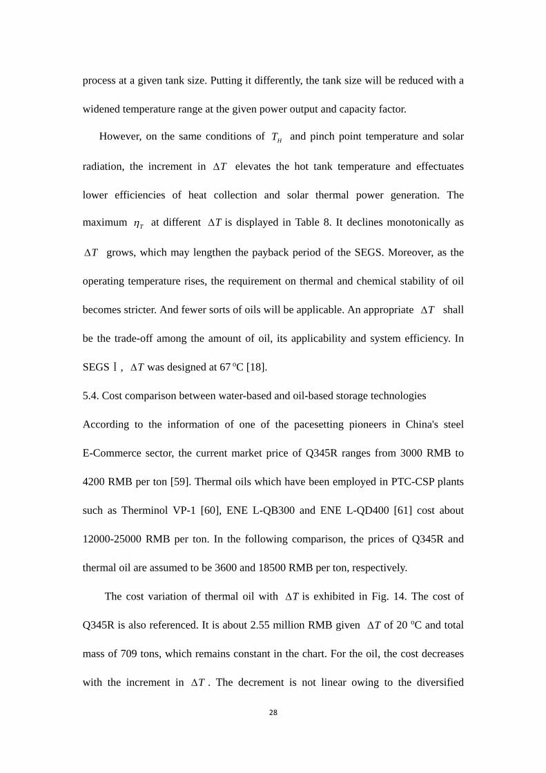
5.3. Parametric effect on thermal oil storage
The two-tank system of oil or molten salt is the most proven utility-scale thermal
storage system, and has been used or projected in many CSP plants including SEGSⅠ,
the 10 MW Solar Two plant, the Andasol plant (1-3, 50 MW per plant) and the 280
MW Solana plant. The temperature range in which the storage unit is operated needs
to be determined at its design stage. If the temperature difference between the hot and
the cold tanks ( T ) is broadened, more heat will be released during the discharge
28
process at a given tank size. Putting it differently, the tank size will be reduced with a
widened temperature range at the given power output and capacity factor.
However, on the same conditions of HT and pinch point temperature and solar
radiation, the increment in T elevates the hot tank temperature and effectuates
lower efficiencies of heat collection and solar thermal power generation. The
maximum T at different T is displayed in Table 8. It declines monotonically as
T grows, which may lengthen the payback period of the SEGS. Moreover, as the
operating temperature rises, the requirement on thermal and chemical stability of oil
becomes stricter. And fewer sorts of oils will be applicable. An appropriate T shall
be the trade-off among the amount of oil, its applicability and system efficiency. In
SEGSⅠ, T was designed at 67 oC [18].
5.4. Cost comparison between water-based and oil-based storage technologies
According to the information of one of the pacesetting pioneers in China's steel
E-Commerce sector, the current market price of Q345R ranges from 3000 RMB to
4200 RMB per ton [59]. Thermal oils which have been employed in PTC-CSP plants
such as Therminol VP-1 [60], ENE L-QB300 and ENE L-QD400 [61] cost about
12000-25000 RMB per ton. In the following comparison, the prices of Q345R and
thermal oil are assumed to be 3600 and 18500 RMB per ton, respectively.
The cost variation of thermal oil with T is exhibited in Fig. 14. The cost of
Q345R is also referenced. It is about 2.55 million RMB given T of 20 oC and total
mass of 709 tons, which remains constant in the chart. For the oil, the cost decreases
with the increment in T . The decrement is not linear owing to the diversified

29
electricity efficiency. At T =100 oC, the oil cost is 7.92 million RMB with a mass of
428.2 tons. The cost superiority of steam accumulator over thermal oil storage is
evident. It is noteworthy that oil needs to be periodically replaced or reprocessed. Its
lifetime is about 5 years, more or less.
The results indicate water as the thermal storage, heat transfer and working fluid
of the SE-based SEGS is feasible. Supported by the data, it is not complicated to find
out the reason why the steam accumulator does not has so good applicability in the
conventional turbine-driven SEGS as in the proposed system. First, the design
pressure is much larger. As pointed out by predecessors, a main steam condition of
500 oC /12 MPa could provide lower LCOE for the PTC-DSG power plant than those
of 400 oC /12 MPa and 500 oC /10 MPa [62]. In this case, the design pressure is 3
times of 4 MPa. Second, the design temperature is higher. The permissible stress of
material generally drops as the operating temperature increases. For example, it is
about 130 MPa -167 MPa for Q345R at 250 oC, and becomes merely 66 MPa at 450
oC. Third, the material gets limited. At temperature above 500 oC, Q345R, Q245R, etc.
are not competent. 15CrMoR could be an alternative, but its price is almost twice of
Q345R [63]. Fourth, the accumulator shall be much thicker. Since cy and head are
approximately proportional to the design pressure and permissible stress, they may be
6 times thicker than those in the SE-related system. The permissible stress will be
further degraded at the same design temperature and pressure as it is a
thickness-dependent parameter. Counting on these issues, the cost of steam
accumulator for the traditional SEGS operating at high temperature and pressure is

30
supposed to transcend that of thermal oil.
5.5. Uncertainty analysis
Thermodynamic performances of the DSG and indirect systems are sensitive to
efficiencies of the PTCs, SE and ORC turbine. The deployed PTCs have optical
efficiency of 0.762, first and second loss coefficients of 0.2125 W/(m2K) and
0.001672 W/(m2K2). The collector efficiency is about 0.585 with solar radiation of
750W/m2 and operating temperature of 250 oC, which is lower than those of products
such as Schott LS-2 [64] and Eurotrough 150 [65]. The SE and ORC turbine have a
design efficiency of 0.75. Isentropic efficiency of around 0.72 for small SE (10-50kW)
has been experimentally reported [66-67]. For large SEs, efficiency approaching 0.80
can be expected [68]. The turbine-based ORC is mature nowadays with installation
capacity more than 1.8 GW [69]. Turbine efficiency above 0.8 is common [70-71].
Constant turbine efficiency is assumed in the optimization. In comparison with SE,
turbine can be designed at a much higher expansion ratio. Nominal efficiency over 0.8
for single-stage axial turbine is expected when the built-in expansion ratio is below 50
[72]. From Table 3, the expansion ratio of R245fa on a recommended working
condition is about 12. Even if the ORC evaporation temperature increases to 140 oC,
the ratio will remain less than 16. Once the optimum working condition is determined,
it is easy to design the turbo-expander accordingly. Besides, multi-stage turbine is
popular for high expansion ratio applications.
Therefore, device efficiencies in the simulation are reasonable and the
thermodynamic performance of the proposed SGES does not seem to be

31
over-estimated. The PTC, SE and ORC turbine are the same in DSG and indirect
systems, if they are replaced the efficiency superiority of the DSG system shall be
retained.
Cost comparison between the DSG and indirect systems are made on the
conditions of thermal storage of 6.5 hours, steel and oil prices of 3600 RMB and
18500 RMB respectively. The prices of steel and oil may change with time. The
storage cost ( ,p steelC , ,p oilC ) can be simply deduced because there is a linear
relationship between ,p steelC , ,p oilC and the material price. ,p steelC and ,p oilC are
also proportional to the storage time.
In the comparison, cascade cycle efficiency ( SORC ) of the DSG system of 23.5%
is employed. However, heat charging and discharging lead to temperature fluctuation
in the accumulator and the power conversion is not steady. The variation of SORC
during the unsteady process is shown in Fig. 15. The design HT is 240 oC. SORC
increases with the increment in the accumulator temperature. The deviation from the
design is within (-0.45%, +0.35%), which is slight. Variation of the equivalent solar
thermal electricity efficiency ( T ) is also depicted in the figure. When heat is released
due to an accumulator temperature decrement from (T T ) to T , equal energy
should be harvested from the solar field in the periodical operation. So the equivalent
T is deemed as the product of SORC and PTC at T . Deviation of T falls within
an interval of (-0.09%, +0.01%).
6. Conclusion
The SE-based DSG solar thermal electricity system using cascade Rankine cycle is

32
designed. The principle is illustrated. By establishing the part-load model on the SE, a
close view to the performance of the proposed system can be brought and
parametrical optimization can be executed. Thermo-economic comparison between
the DSG and indirect systems is made, followed by further discussion on the
uncertainty.
Maximum solar thermal electricity efficiency ( ,T m ) and optimum hot side
temperature of the SORC ( ,H opT ) are 14.3% and 240 oC respectively under beam solar
radiation of 750 W/m2 for the DSG SGES. There are deviations of (-0.9%, +0.6%) in
,T m and (-20 oC, +10 oC) in ,H opT when the radiation range is widened from 600
W/m2 to 900 W/m2. ,H opT for system’s annual operation in six territories of abundant
solar energy resource i.e. Phoenix, Sacramento, Cape Town, Canberra, Barcelona and
Lhasa falls within (220 oC, 240 oC).
Replacing the DSG solar field by collectors working with thermal oil, both ,T m
and ,H opT are decreased on the same conditions of solar radiation and environment
temperature. The decrement in ,T m is about 1.1% at 750 W/m2, which turns more
appreciable at lower radiation. And the annual electricity generation suffers from a
yield drop around 10% in the six areas.
Aside from the thermodynamic benefits, the DSG system has cost advantage over
the indirect one in terms of storage. The concept of using steam accumulators for heat
storage in DSG plant has been discussed in the literatures. In this work, mathematical
model is built and the material cost of the accumulators is analyzed in detail at an
eligible design temperature of 250 oC. The horizontal pressure vessels appear to save

33
more material of steel than the vertical ones. And the total occupied mass tends to
decrease with the decrement in the vessel diameter. Multi-vessels functioning in
parallel can effectively reduce the device length. When 6 vessels of length of 25 m are
used and a temperature drop of 20 oC during heat discharge ( T ) is assumed, an
amount of 709 tons of Q345R is needed for 6.5 h storage in a 1 MW plant.
To facilitate a similar storage using the two-tank HTF system, the required oil is
428.2 tons on the assumption of T =100 oC. In accordance with the current market
price, the thermal oil cost is three times more than that of the steel material for steam
accumulators.
Acknowledgment
This study was sponsored by the National Science Foundation of China (51476159,
51378483, 51206154), EU Marie Curie International Incoming Fellowships Program
(703746), Anhui Provincial Natural Science Foundation (1608085QE96) and
Dongguan Innovative Research Team Program (2014607101008).
Reference
[1] Opcon Powerbox Product Sheet.
<http://opconenergysystem.com/en/opcon-powerbox-wst-cu/> [06.08.16].
[2] Why Heliex. <www.heliexpower.com/why-heliex/whats-required/> [20.08.16].
[3] Parameters & Specifications.
<http://www.jxhdep.com/newsInfo.asp?pid=88&small=89&id=237> [25.08.16].

34
[4] Specifications. <http://qyexpander.com/chanpin.htm> [14.08.16].
[5] The Power+ 6500 comes in two configurations – Stand alone or turnkey package.
<https://electratherm.com/products/power-plus-generator-6500-up-to-110kwe>
[31.01.17].
[6] ORC Screw Expansion Power Station.
<http://www.denair.net/ORC/ORC_screw_expansion_power_station.html>
[30.01.17].
[7] Zhai H, Dai YJ, Wu JY, Wang RZ. Energy and exergy analyses on a novel hybrid
solar heating, cooling and power generation system for remote areas. Appl Energy
2009; 86: 1395-404.
[8] Astolfi M. Techno-economic optimization of low temperature CSP systems based
on ORC with screw expanders. Energy Procedia 2015; 69: 1100-12.
[9] Joung J, Cho H. Theoretical analysis of a small-scale solar power system using an
R-245fa Rankine cycle with a scroll and twin screw expander. WIT Transactions on
Ecology and The Environment 2015; ISSN 1743-3541: 206-17.
[10] CLEAN ELECTRICITY FROM WET STEAM.
<http://www.rushlightevents.com/wp-content/uploads/2014/01/R-Show-14-SSMP-He
liex-Power.pdf> Heliex Power Ltd. [31.01.17].
[11] Merigoux JM, Pocard P. Solar power units with screw expanders. In: Solar
energy: International progress; Proceedings of the International
Symposium-Workshop, Cairo, Egypt, June 16-22, 1978. vol. 3. New York, Pergamon
Press, Inc., 1980, p. 1293-317.

35
[12] Song J, Gu CW. Performance analysis of a dual-loop organic Rankine cycle
(ORC) system with wet steam expansion for engine waste heat recovery. Appl Energy
2015; 156: 280-9.
[13] Tang Y. Single stage and cascaded organic Rankine cycles with screw expanders
used for hot fluids in oil refineries and chemical plants. 16th International
Refrigeration and Air Conditioning Conference at Purdue, July 11-14, 2016.
[14] Zhang HG, Wang EH, Fan BY. A performance analysis of a novel system of a
dual loop bottoming organic Rankine cycle (ORC) with a light-duty diesel engine.
Appl Energy 2013; 102: 1504-13.
[15] Li J, Li PC, Pei G, Alvi JZ, Ji J. Analysis of a novel solar electricity generation
system using cascade Rankine cycle and steam screw expander. Appl Energy 2016;
165: 627-38.
[16] James E, Pacheco. Demonstration of solar-generated electricity on demand: the
solar two project. J. Sol. Energy Eng-Transactions of the ASME 2001; 123: 5.
[17] Medrano M, Gil A, Martorell I, Potau X, Cabeza LF. State of the art on
high-temperature thermal energy storage for power generation. Part 2-Case studies.
Renewable & Sustainable Energy Reviews 2010; 14: 56-72.
[18] Solar Electric Generating Station I.
<http://www.nrel.gov/csp/solarpaces/project_detail.cfm/projectID=28> [13.09.16].
[19] Huang SY, Huang SH. Solar thermal power generation principle and technology.
China Electric Power Press, Chapter Ten 2012: 446.
[20] Laing D, Bahl D, Bauer T, Lehmann D, Steinmann WD. Thermal energy storage

36
for direct steam generation. Sol Energy 2011; 85: 627-33.
[21] Birnbaum J, Eck M, Fichtner M, Hirsch T, Lehmann D, Zimmermann G. A direct
steam generation solar power plant with integrated thermal storage. 14th Biennial
CSP SolarPACES (Solar Power and Chemical Energy Systems) Symposium, Las
Vegas, USA, NREL/CD-550-42709; 2008.
[22] Bai FW, Xu C. Performance analysis of a two-stage thermal energy storage
system using concrete and steam accumulator. Appl Therm Eng 2011; 31: 2764-71.
[23] Garcia1 P, Vuillerme V, Olcese M, Mourchid NE. Design and modelling of an
innovative three-stage thermal storage system for direct steam generation CSP plants.
AIP Conf. Proc 2016; 1734: 050015.
[24] Steinmann WD, Eck M. Buffer storage for direct steam generation. Sol Energy
2006; 80: 1277-82.
[25] SOLUCAR. PS10: 10 MW solar thermal power plant for southern Spain.
NNE5-1999-356; 2016.
[26] Planta Solar 20. National Renewable Energy Laboratory.
<http://www.nrel.gov/csp/solarpaces/project_detail.cfm/projectID=39> [22.06.16].
[27] Feldhoff JF, Schmitz K, Eck M, Schnatbaum-Laumann L, Laing D, Ortiz-Vives F,
Schulte-Fischedick J. Comparative system analysis of direct steam generation and
synthetic oil parabolic trough power plants with integrated thermal storage. Sol
Energy 2012; 86: 520-30.
[28] Ruiz-Cabañas FJ, Prieto C, Osuna R, Madina V, Fernández AI, Cabeza LF.
Corrosion testing device for in-situ corrosion characterization in operational molten

37
salts storage tanks: A516 Gr70 carbon steel performance under molten salts exposure.
Sol. Energ. Mater. Sol. Cells 2016; 157: 383-92.
[29] Sau S, Corsaro N, Crescenzi T, D’Ottavi C, Liberatore R, Licoccia S, Russo V,
Tarquini P, Tizzoni AC. Techno-economic comparison between CSP plants presenting
two different heat transfer fluids. Appl Energy 2016; 15: 96-109.
[30] Srivastava AK, Kudariyawar JY, Borgohain A, Jana SS, Maheshwari NK,
Vijayan PK. Experimental and theoretical studies on the natural circulation behavior
of molten salt loop. Appl Therm Eng 2016; 98: 513-21.
[31] Dorcheh AS, Galetz MC. Slurry aluminizing: A solution for molten nitrate salt
corrosion in concentrated solar power plants. Sol. Energ. Mater. Sol. Cells 2016; 146:
8-15.
[32] Myers Jr PD. Alamb TE, Kamal R, Goswami DY, Stefanakos E. Nitrate salts
doped with CuO nanoparticles for thermal energy storage with improved heat transfer.
Appl Energy 2016; 165: 225-33.
[33] Vignarooban K, Xu X, Wang K, Molina EE, Lic P, Gervasio D, Kannan AM.
Vapor pressure and corrosivity of ternary metal-chloride molten-salt based heat
transfer fluids for use in concentrating solar power systems. Appl Energy 2015; 159:
206-13.
[34] Smith IK, Stosic N, Kovacevic A. Screw expanders increase output and decrease
the cost of geothermal binary power plant systems. Transactions of Geothermal
Resource 2005.
[35] Papes I, Degroote J, Vierendeels J. New insights in twin screw expander

38
performance for small scale ORC systems from 3D CFD analysis. Appl Therm Eng
2015; 91: 535-46.
[36] Read M, Stosic N, Smith IK. Optimization of screw expanders for power
recovery from low-grade heat sources. Energy Technol Policy 2014; 1: 131-42.
[37] Invernizzi C, Iora P, Silva P. Bottoming micro-Rankine cycles for micro-gas
turbines. Appl Therm Eng 2007; 27: 100-10.
[38] Ng KC, Bong TY, Lim TB. A thermodynamic model for the analysis of screw
expander performance. Heat Recov Syst CHP 1990; 10: 119-33.
[39] Li J, Pei G, Li YZ, Wang DY, Ji J. Energetic and exergetic investigation of an
organic Rankine cycle at different heat source temperatures. Energy 2012; 38: 85-95.
[40] Nag HPK. Power Plant Engineering. Tata McGraw-Hill Education 2008 ISBN:
0070648158: 107.
[41] Cascade refrigeration stem.
<http://www.nissin-ref.co.jp/english/product_blog/1-2.html> [20.01.17].
[42] Eck M, Hennecke K. Heat transfer fluids for future parabolic trough solar
thermal power plants. Proceedings of ISES Solar World Congress 2007: Solar Energy
and Human Settlement.
[43] Kruger D, Heller A, Hennecke K, Duer K. Parabolic trough collectors for district
heating systems at high latitudes: a case study. Proceedings of Eurosun 2000.
[44] Soteris A. Kalogirou. Solar thermal collectors and applications. Progress in
energy and combustion science 2004; 30: 231-95.
[45] Ng KC, Lira TB, Bong TY. Analysis of screw expander performance. Proc.

39
Insm Mechn. Engrs Part E 1989; 203: 15-20.
[46] Gordon FC, Rogers, Mayhew YR. Engineering Thermodynamics—Heat and
Work Transfer. ELBS Book 1964.
[47] Koto-Ku B. Screw type steam engine. Internal report of Mayekawa Mfg Co Ltd,
Japan 1984; 2-3-1: Tokyo 135.
[48] Hettiarachchi HDM, Golubovic M, Worek WM, Ikegami Y. Optimum design
criteria for an Organic Rankine cycle using low-temperature geothermal heat sources.
Energy 2007; 32: 1698-706.
[49] Cataldo F, Mastrullo R, Mauro AW, Vanoli GP. Fluid selection of organic
Rankine cycle for low-temperature waste heat recovery based on thermal optimization.
Energy 2014;72: 159-67.
[50] Vessel Cost Estimate. <http://matche.com/equipcost/Vessel.html> [26.07.16].
[51] Steel pressure vessels. National Standard of the People's Republic of China. GB
150-1998, pp:28.
[52] Heads for pressure vessels. National Standard of the People's Republic of China.
GB/T 25198-2010, pp:13。
[53] Elliptical heads. Standards of the Machinery Department of the People's
Republic of China. JB1154-73.
[54] Steel plates for boilers and pressure vessels. National Standard of the People’s
Republic of China. GB 713-2008.
[55] Li J, Alvi JZ, Pei G, Su YH, Li PC, Gao GT, Ji J. Modelling of organic Rankine
cycle efficiency with respect to the equivalent hot side temperature. Energy 2016; 115:

40
668-83.
[56] Weather Data. <https://energyplus.net/weather> Energyplus [12.04.16]
[57] ASME, ASME Boiler & Pressure Vessel Code Case 2642, American Society of
Mechanical Engineers, New York 2010.
[58] Steel plates for boilers and pressure vessels. National Standard of the People’s
Republic of China. GB 713-2014.
[59] FOB prices of steel products. <http://www.mysteel.net/> Shanghai Ganglian
E-Commerce Co., Ltd. [25.9.16].
[60] THERMINOL® P-1. <http://www.szsolutia.com/productse_detail/id/7.html>
Solutia Therminol Co. Ltd., Suzhou. [25.9.16].
[61] ENE L-QD400. <http://www.enesoon.com.cn/en/> Enesoon. [25.9.16].
[62] Feldhoff JF, Benitez D, Eck M, Riffelmann KJ. Economic potential of solar
thermal power plants with direct steam generation compared with HTF plants. J Solar
Energy Eng 2010; 132: 041001.
[63] FOB prices of steel products. <http://www.mysteel.net/> Shanghai Ganglian
E-Commerce Co., Ltd. [25.9.16].
[64] Moss TA, Brosseau DA. Final Test Results for the Schott HCE on a LS-2
Collector. SANDIA REPORT. July 2005. SAND 2005-4034.
[65] Geyer M, Lerchenmüller H, Wittwer V, Häberle A, Lüpfert E, Hennecke K,
Schiel W, Brakmann G: Parabolic trough system. FVS Themen 2002.
[66] Hsu SW, Chiang HWD, Yen CY. Experimental investigation of the performance
of a hermetic screw-expander organic Rankine cycle. Energies 2014; 7: 6172-85.

41
[67] Avadhanula VK, Lin CS. Empirical models for a screw expander based on
experimental data from organic Rankine cycle system testing. J Eng Gas Turbines
Power 2014; 136: 062601-1.
[68] Smith IK. Review of the development of two-phase screw expanders. Progress in
the Development of Twin Screw Machines.
<http://www.staff.city.ac.uk/~sj376/smith99.htm> [01.02.17].
[69] Li J. Structural optimization and experimental investigation of the organic
Rankine cycle for solar thermal power generation. Thesis, Springer 2015; ISBN
978-662-45622.
[70] Biomass cogeneration. Turboden
<http://www.turboden.eu/en/applications/applications-biomass.php> [01.02.17].
[71] Sauret E, Gu YT. Three-dimensional off-design numerical analysis of an organic
Rankine cycle radial-inflow turbine. Appl Energy 2014; 135: 202-11.
[72] Shu G, Li X, Tian H, Liang X, Wei H, Wang X. Alkanes as working fluids for
high-temperature exhaust heat recovery of diesel engine using organic Rankine cycle.
Applied Energy 2014; 119: 204-17.
Figure Legends
Fig. 1. DSG solar cascade Rankine cycle system
Fig. 2. Solar cascade Rankine cycle system with thermal oil
Fig.3. T-s diagram of the cascade cycle
Fig. 4. Cross-section of elliptical head
Fig. 5. Different placements of pressure vessel

42
Fig. 6. Variations of the collector and cascade cycle efficiencies with the hot side
temperature
Fig. 7. Variations of solar thermal power efficiencies with the hot side temperature
Fig. 8. Variation of the optimum hot side temperature with radiation
Fig. 9. Variation of maximum solar thermal power efficiency with radiation
Fig. 10. Variations of total mass and design pressure of Q345R with the diameter of
vessel of vertical symmetrical axis
Fig. 11. Variations of total mass and length of the vessel of horizontal symmetrical
axis with the diameter
Fig. 12. Variations of the total mass and the diameter with number of vessels in use
for vertical placement
Fig. 13. Variations of the total mass and the diameter with number of vessels in use
for horizontal placement
Fig. 14. Cost comparison between thermal oil and Q345R
Fig. 15. Variations of the cascade cycle efficiency and equivalent solar thermal power
efficiency with the accumulator temperature in the heat charging/discharging process
Table Legends
Table 1. Permissible stress for some materials
Table 2. Fixed parameters
Table 3. Parameter distribution of the DSG system when maximum solar thermal
power efficiency is achieved
Table 4. Parameter distribution of the indirect system when maximum solar thermal

43
power efficiency is achieved
Table 5. Optimum TH and maximum power output in six regions
Table 6. Quality of different components for Q345R, unit: %.
Table 7. Design thickness under different working conditions for Q345R, unit: mm
Table 8. Maximum thermal power efficiency at different temperature drops from the
hot to the cold tank
Fig. 1. DSG solar cascade Rankine cycle system

44
Fig. 2. Solar cascade Rankine cycle system with thermal oil
P1
P2
V1
V2
P3
PTC
ScrewExpander
TurbineHX1
HX2
coldoil
tank
1
2
3
45
6
7
8
hotoil
tank
HX3
P4

45
1 2 3 4 5 6 7 80
50
100
150
200
250
300
350
400
T(o
C)
S(kJ/kgK)
87
6
5
43
2
1
Fig.3. T-s diagram of the cascade cycle
Fig. 4. Cross-section of elliptical head

46
Fig. 5. Different placements of pressure vessel: (a) vertical; (b) horizontal
200 220 240 260 280 300 320 340
40
45
50
55
60
65
Solar collector efficiency for DSG systemSolar collector efficiency for indirect systemSORC efficiency
So
lar
colle
cto
re
ffic
ien
cy(%
)
TH (oC)
21
22
23
24
25
26S
OR
Ce
ffic
ien
cy(%
)
Fig. 6. Variations of the collector and cascade cycle efficiencies with the hot side
temperature
47
200 220 240 260 280 300 320 340 36010.0
10.5
11.0
11.5
12.0
12.5
13.0
13.5
14.0
Power efficiency for DSG systemPower efficiency for indirect system
TH (OC)
So
lar
the
rma
lpo
we
re
ffic
ien
cy(%
)
Fig. 7. Variations of solar thermal power efficiencies with the hot side temperature
300 400 500 600 700 800 900
160
180
200
220
240
260 DSG systemIndirect system
Optim
um
ho
tsi
de
tem
pe
ratu
re(o
C)
Gb (W/m2)
Fig. 8. Variation of the optimum hot side temperature with radiation

48
300 400 500 600 700 800 900
9
10
11
12
13
14
15DSG systemIndirect system
Gb (W/m2)
Ma
xim
um
so
lar
the
rma
lpo
we
re
ffic
ien
cy
(%)
Fig. 9. Variation of maximum solar thermal power efficiency with radiation
0 1500 3000 4500 6000 7500 9000 10500
800
1200
1600
2000
2400
2800
3200
3600
4000mass
To
talm
ass
(to
nn
e)
Diameter (mm)
3
4
5
6
7
8
9
10
11
pressureD
esig
np
ress
ure
(MP
a)
Fig. 10. Variations of total mass and design pressure of Q345R with the diameter of
vessel of vertical symmetrical axis

49
0 1500 3000 4500 6000 7500 9000 10500500
600
700
800
900
1000
1100mass
Tota
lma
ss(t
on
ne
)
Diameter (mm)
0
100
200
300
400
500
600
700
800
length
Le
ng
th(m
)
Fig. 11. Variations of total mass and length of the vessel of horizontal symmetrical
axis with the diameter
0 2 4 6 8 10 12700
750
800
850
900
950
mass
To
talm
ass
(ton
ne
)
Number
2000
3000
4000
5000
6000
7000
8000
Dia
mte
r(m
m)
diameter
Fig. 12. Variations of the total mass and the diameter with number of vessels in use
for vertical placement

50
0 2 4 6 8 10 12650
700
750
800
850
900
mass
To
talm
ass
(to
nn
e)
Number
2000
3000
4000
5000
6000
7000
8000diameter
Dia
me
ter
(mm
)
Fig. 13. Variations of the total mass and the diameter with number of vessels in use
for horizontal placement
50 60 70 80 90 1000
3
6
9
12
15
Co
st(m
illio
nR
MB
)
Temperature drop of oil during heat discharge (℃)
Cost of oilCost of steel
Fig. 14. Cost comparison between thermal oil and Q345R

51
228 232 236 240 244 248 252
14
16
18
20
22
24
26 SORC efficiency
Solar thermal power efficiency
Eff
icie
ncy
(%)
TH (OC)
Fig. 15. Variations of the cascade cycle efficiency and equivalent solar thermal power
efficiency with the accumulator temperature in the heat charging/discharging process

52
Table 1. Permissible stress for some materials [54], unit: MPa
Type Standard Thickness
/mm
Temperature / oC
200 250 300 350 400 450
Q245R GB 713 3-16 131 117 108 98 91 61
>16-36 124 111 102 93 86 61
>36-60 119 107 98 89 82 61
>60-100 109 98 90 82 75 61
>10-150 100 90 80 73 70 61
Q345R GB 713 3-16 183 167 153 143 125 66
>16-36 170 157 143 133 125 66
>36-60 160 147 133 123 117 66
>60-100 150 137 123 117 110 66
>100-150 147 133 120 113 107 66
>150-200 143 130 117 110 103 66
15CrMoR GB 713 6-60 160 150 140 133 126 119
>60-100 147 140 131 124 117 111
>100-150 140 133 123 117 110 104
Q370R 10~16 196 190 180 170
>16~36 193 183 173 163
>36~60 180 170 160 150
16MnDR GB 3531 6-16 167 153 140 130
>16-36 157 143 130 120
>36-60 150 137 123 117
>60-100 147 133 120 113
>100-120 143 130 117 110
09MnNiDR GB 3531 6-16 160 153 147 137
>16-36 150 143 137 127
>36-60 143 137 130 120
>60-120 140 133 127 117
53
Table 2. Fixed parameters
Term Value
Pinch-point temperature difference, ppT 5 K
Pump efficiency, p 0.8
Peak isentropic efficiency of SE, ,os p 0.75
Turbine isentropic efficiency, T 0.75
Generator efficiency, g 0.95
Built-in volume ratio of SE, ,v br 5
Ambient temperature, aT 25
Welding coefficient, 0.8
Gravity, g 9.8 m/s2
Net power output, netW 1 MW
Capacity of heat storage, Ht 6.5 hours

54
Table 3. Parameter distribution of the DSG system when maximum solar thermal
power efficiency is achieved
bG (W/m2) 600 750 900
T1(oC) / P1(MPa) 220 / 2.32 240 / 3.35 250 / 3.98
T2(oC) / P2(MPa) 121 / 0.21 130 / 0.27 134 / 0.30
T3(oC) / P3(MPa) 121 / 0.21 130 / 0.27 134 / 0.30
T4(oC) / P4(MPa) 121.31 / 2.32 130.47 / 3.35 134.58 / 3.98
T5(oC) / P5(MPa) 116 / 1.78 125 / 2.13 129 / 2.30
T6(oC) / P6(MPa) 55.22 / 0.18 56.58 / 0.18 56.89 / 0.18
T7(oC) / P7(MPa) 30 / 0.18 30 / 0.18 30 / 0.18
T8(oC) / P8(MPa)
T (%)
30.81 / 1.78 30.99 / 2.13 31.07 / 2.30
13.38 14.24 14.90

55
Table 4. Parameter distribution of the indirect system when maximum solar thermal
power efficiency is achieved
bG (W/m2) 600 750 900
T1(oC) / P1(MPa) 210 / 1.91 230 / 2.80 240 / 3.35
T2(oC) / P2(MPa) 114 / 0.16 126 / 0.24 130 / 0.27
T3(oC) / P3(MPa) 114 / 0.16 126 / 0.24 130 / 0.27
T4(oC) / P4(MPa) 114.25 / 1.91 126.39 / 2.80 130.47 / 3.35
T5(oC) / P5(MPa) 109 / 1.54 121 / 1.97 125 / 2.13
T6(oC) / P6(MPa) 53.70 / 0.18 56.09 / 0.18 56.58 / 0.18
T7(oC) / P7(MPa) 30 / 0.18 30 / 0.18 30 / 0.18
T8(oC) / P8(MPa)
T (%)
30.69 / 1.54 30.90 / 1.97 30.99 / 2.13
12.25 13.23 13.99

56
Table 5. Optimum TH and maximum power output in six regions
Region
DSG system Indirect system
Optimum
TH (oC)
Maximum
power output
(kWh·m-2·year-1)
Optimum
TH (oC)
Maximum
power output
(kWh·m-2·year-1)
Phoenix 240 351.16 220 322.33
Sacramento 240 294.99 220 270.46
Cape Town 230 252.78 210 230.75
Canberra 220 227.50 200 209.89
Barcelona 210 206.46 200 186.73
Lhasa 200 214.87 190 193.03
Table 6. Quality of different components for Q345R [58], unit: %
Component value Component value Component value
C ≤0.20 Si ≤0.55 Cu ≤0.30
Ni ≤0.30 Cr ≤0.30 Mo ≤0.08
Nb ≤0.05 V ≤0.05 Ti ≤0.03
Alt >0.02 P ≤0.025 S ≤0.01
Mn 1.2-1.7

57
Table 7. Design thickness under different working conditions for Q345R, unit: mm
Di
mm
200 oC 250 oC 300 oC
1.6 MPa 2.1 MPa 2.6 MPa 4.0 MPa 4.5 MPa 5.0 MPa 8.6 MPa
1000 5.49 7.22 8.96 15.20 18.08 20.10 40.76
1500 8.24 10.84 13.44 24.08 27.11 30.16 66.22
2000 10.99 14.45 19.21 32.10 38.63 42.97 88.29
2500 13.74 19.38 24.01 42.88 48.29 53.72 113.18
3000 17.70 23.25 28.81 51.46 57.95 69.22 135.82
3500 20.65 27.13 33.62 64.46 72.60 80.76 162.61
4000 23.60 31.00 40.83 73.66 82.97 92.29 185.84
4500 26.55 34.88 45.94 82.87 93.34 106.99 209.07
5000 29.50 41.18 51.04 92.08 106.86 118.88 232.30
5500 32.45 45.30 56.14 104.36 117.55 130.77 255.53
6000 35.40 49.42 65.35 113.85 128.24 142.65 278.76
6500 40.75 53.54 70.80 123.34 138.92 158.15 302.00
7000 43.89 57.66 76.25 132.83 149.61 170.32 325.23

58
Table 8. Maximum thermal power efficiency at different temperature drops from
the hot to the cold tank
Temperature difference
during discharge (oC)
50 60 70 80 90 100
Oil inlet temperature (oC) 227.23 224.40 221.18 218.37 215.59 212.86
Oil outlet temperature (oC) 277.23 284.40 291.18 298.37 305.59 312.86
TH (oC) 227 226 225 224 223 222
Maximum thermal power
efficiency (%)
13.23 13.13 13.02 12.91 12.80 12.68

59
Nomenclature
A aperture area, 2m Subscripts
surface area, 2mm Ⅰ CycleⅠ
a half long axis, mm Ⅱ Cycle Ⅱ
b half short axis, mm 0 reference state
C total cost, RMB 1–8 state points
D diameter, mm a ambient
G solar radiation, 2/ mW b binary phase/ beam/ built-in
g gravity, 2/ sm C cold side
H height, mm ch characteristic
h enthalpy, kgkJ /
edge height of head, mm
cy
F
cylinder
friction
M mass, kg g generator/ static
m mass flow rate, /kg s H hot side/ hour
P cost per kilogram, /RMB kg head elliptical head
p pressure, MPa i diagram
r ratio in inlet
T temperature, o C L leakage
V total volume, 3mm l liquid phase
v specific volume, 3 /cm kg M mechanical
W power output, kW m maximum
thickness, mm net net

60
device efficiency oil oil
welding coefficient op optimum
isentropic index os overall isentropic
system efficiency out outlet
[ ]t permissible stress, MPa P peak
density, 3/ mkg p pressure/ pump
Abbreviation pp pinch-point
DSG direct steam generation S shaft
HTF heat transfer fluid s storage/isentropic/steam
HX heat exchanger steel steel
ORC organic Rankine cycle su supply
P pump T thermal/ turbine
PCM phase-change material t total mass flowrate
PTC parabolic trough collector T D diagram
SE
SEGS
screw expander
solar electricity generation system
Th
T I
theoretical
isentropic
SORC steam-organic Rankine cycle TM thermodynamic
SRC steam Rankine cycle v volume
V valve w water