THERMODYNAMIC ANALYSIS OF GAS TURBINE
39
THERMODYNAMIC ANALYSIS OF GAS TURBINE BY AHMAD NURAIZAT BIN SULAIMAN MECHANICAL ENGINEERING 11427 Dissertation submitted in partial fulfillment of the requirements for the Bachelor of Engineering (Hons) (Mechanical Engineering) MAY 2012 UNIVERSITI TEKNOLOGI PETRONAS BANDAR SERI ISKANDAR 31750 TRONOH PERAK DARUL RIDZUAN brought to you by CORE View metadata, citation and similar papers at core.ac.uk provided by UTPedia
Transcript of THERMODYNAMIC ANALYSIS OF GAS TURBINE

THERMODYNAMIC ANALYSIS OF GAS TURBINE
BY
AHMAD NURAIZAT BIN SULAIMAN
MECHANICAL ENGINEERING
11427
Dissertation submitted in partial fulfillment of
the requirements for the
Bachelor of Engineering (Hons)
(Mechanical Engineering)
MAY 2012
UNIVERSITI TEKNOLOGI PETRONAS
BANDAR SERI ISKANDAR
31750 TRONOH
PERAK DARUL RIDZUAN
brought to you by COREView metadata, citation and similar papers at core.ac.uk
provided by UTPedia
I
CERTIFICATION OF APPROVAL
Thermodynamic Analysis of Gas Turbine
By
Ahmad Nuraizat Bin Sulaiman
A project dissertation submitted to the
Mechanical Engineering Programme
University Teknologi PETRONAS
In partial fulfilment of the requirement for the
BACHELOR OF ENGINEERING (Hons) OF
(MECHANICAL ENGINEERING)
Approved by,
..............................
(Dr Aklilu Tesfamichael Baheta)
UNIVERSITY TEKNOLOGI PETRONAS
TRONOH, PERAK
MAY 2012

II
CERTIFICATION OF ORIGINALITY
This is to certify that I am responsible for the work submitted in this project, that the
original work is my own except as specified in the references and acknowledgment, and
that the original work contained herein have not been undertaken or done by unspecified
source or persons.
.......................................
AHMAD NURAIZAT BIN SULAIMAN
890422-03-6159
III
ACKNOWLEDGEMENT
First and foremost I would like to express my highest gratitude to the Allah S.W.T, which
has been guiding and supporting me throughout my entire life in general and during
taking this project in specific.
I would like to express my humble gratitude toward my FYP supervisor, Dr Aklilu
Tesfamichael Baheta for his continuous belief in my ability to conduct this project
successfully. His continuous supports and advices to me in completing the FYP project
are very crucial. Without his firm and strict judgments, this project would be nowhere
until today. I appreciate his effort and time to assist me in doing the reports and giving
me assistance in doing simulation work.
Then I would like to express my warm gratitude towards my friends that are doing the
same FYP project discipline with me. Their help and support mean a lot to me to
complete this project. I would also like to express my thankfulness towards my parents,
my family and all the lecturers in UTP for contribution to what I have today. Last but not
least, special thank to PETRONAS for giving me the opportunity to study in University
Teknologi PETRONAS (UTP) and completed my first degree in Mechanical
Engineering.
Thank you.

IV
ABSTRACT
This project is intended to do analysis of a gas turbine engine performance. The gas
turbine operating conditions (pressure ratio, turbine inlet and exhaust temperatures, fuel
to air ratio, isentropic compressor and turbine efficiencies and ambient temperature)
affect the turbine performance. The performance indicators are thermal efficiency,
compressor work, power output, specific fuel consumption and heat rate. This project
will focus on the effect of ambient temperature, turbine inlet temperature, air to fuel ratio
and compression ratio on the efficiency and output power of the turbine. The gas turbine
basic components were modelled based on thermodynamics principle. The developed
components models were integrated using conservation of mass and energy balance. In
solving mathematical equation of every component, Microsoft Office Excel software was
used. The simulation result could be use to suggest the optimum cycle operating
condition.

V
LIST OF FIGURES
Figure 1.1 Schematic diagram for simple gas turbine 3
Figure 1.2 Brayton Cycle 4
Figure 1.3 (a) P-V diagram and (b) T-S diagram for gas turbine 4
Figure 1.4 Siemens (SGT-750) Gas Turbine 5
Figure 1.5 Gas Turbine Plant Layout 6
Figure 2.1 Effect of ambient temperature on a gas turbine
(Saravanamuttoo et al., 2009) 11
Figure 2.2 World’s First Industrial Gas Turbines with Single Combustor
(Zurcher et al., 1988) 13
Figure 2.3 Temperature and Entropy Diagram for Gas Turbine 13
Figure 3.1 Research Methodology for thermodynamics
analysis of gas turbine 18
Figure 3.2 Simulation Glow Chart in Microsoft Excel
Figure 4.1 Variation of compression ratio, turbine inlet temperature (TIT)
and ambient temperature on thermal efficiency 23
Figure 4.2 Variation of compression ratio and fuel to air ratio (FAR)
on thermal efficiency 24
Figure 4.3 Effect of compression ratio and ambient temperature
on compressor work 25
Figure 4.4 Effect of ambient temperature and fuel to air ratio (FAR)
on thermal efficiency 26
Figure 4.5 Effect of ambient temperature and fuel to air ratio (FAR)
on power 27

VI
LIST OF TABLE
Table 3.1 Gantt Chart (FYP I) 21
Table 3.2 Gantt Chart (FYP II) 21

1
TABLE OF CONTENTS
CERTIFICATION OF APPROVAL I
CERTIFICATION OF ORIGINALITY II
ACKNOWLEDGEMENT III
ABSTRACT IV
LIST OF FIGURE V
LIST OF TABLE VI
CHAPTER 1: INTRODUCTION
1.1 Background of Study 3
1.2 Problem Statement 7
1.3 Objective 8
1.4 Scope of Study 8
1.5 Relevancy of Project 9
CHAPTER 2: LITERATURE REVIEW
2.1 Literature Review 10
2.2 Thermodynamic Modelling
of Gas Turbine 13
CHAPTER 3: METHODOLOGY
3.1 Research Methodology 18
3.2 Simulation Flow Chart 19
3.3 Project Activities 20
3.4 Gantt Chart and Key Milestone 21

2
CHAPTER 4: RESULT AND DISCUSSION
4.1 Simulation Result and Discussion 22
CHAPTER 5: CONCLUSION AND RECOMMENDATION
5.1 Conclusion 28
5.2 Recommendation 29
REFERENCES 30
APPENDICES 32

3
CHAPTER 1
INTRODUCTION
1.1 BACKGROUND OF STUDY
Gas turbine power plants consist of four components which are compressor,
combustion chamber, turbine and generator. A schematic diagram for simple gas
turbine is shown in Figure 1.1. Air is drawn by the compressor and delivered to the
combustion chamber. Combustion occurs in combustion chamber with the mix of fuel
and air then produces flue gas. High temperature flue gas is leaving the combustion
chamber, entering turbine inlet and expands in the turbine which produces work by
turning turbine blade. The corresponding thermodynamic cycle that is used to model
the gas turbine working principle is Brayton cycle and it’s shown in Figure 1.2.
Figure 1.1: Schematic diagram for simple gas turbine

4
Figure 1.2: Brayton Cycle
Efficient compression of large volume of air is essential for a successful gas turbine
power plant. This has been achieved in two types of compressors, the axial flow
compressor and the centrifugal or radial flow compressors. Most power plant
compressor design is to obtain the most air through a given diameter compressor with
a minimum number of stages while retaining relatively high efficiency and
aerodynamic stability over the operating range. The ideal processes and actual
processes are represented in full line and dashed line, respectively, on the T-S
diagram Figure 1.3. These parameters in terms of temperature are defined as (Al-
Sayed, 2008):
Figure 1.3: (a) P-V diagram and (b) T-S diagram for gas turbine
1

5
Figure 1.4 shows the example of gas turbine, Siemens Gas Turbine (SGT-750). The
SGT 750 is a twin shaft gas turbine with a free power turbine and it can be employed
both for power generation and as a mechanical drive. This gas turbine attains an
efficiency level of 40% and has a capacity of 37 megawatts (MW). Gas turbine plant
layout is shown in Figure 1.5 based on the Siemens SGT-750 Manual (Anders, 2010).
Gas turbines are rapidly becoming the choice for current and future power generation
systems because they offer efficient fuel conversion, reduced cost of electricity, low
installation and maintenance cost, can be put in service with minimum of delay time,
occupy less room than other plants for the same capacity, and the ability to consume
wide range of hydrocarbon fuels (Nag, 2008). Their exhaust gases are relatively less
pollutant to the environment and can be used for preheating air before entering the
combustion chamber, or for district heating as in combined heat and power plants
(Wang and Chiou, 2002).
Figure 1.4: Siemens (SGT-750) Gas Turbine

6
Figure 1.5: Gas Turbine Plant Layout
7
1.2 PROBLEM STATEMENT
A study from Taniquchi and Miyamae in 2000 reveals that, until mid seventies,
mostly gas turbine suffered because of low efficiency and poor reliability. This
limited the use of gas turbines to fulfill peak power demand. Based on recent study,
performance of the gas turbine is closely related to the behavior of its operating
conditions. Ambient temperature of air is draw by the compressor might influence the
power output of the gas turbine. Power rating of a gas turbine may drop by as much
as 20% to 30%, with respect to international standard organization (ISO) design
condition, when ambient temperature reaches among 350C to 45
0C. Most gas turbines
typically produce 30% higher electric output when the ambient air temperature is
150C compared to 45
0C (Mahmood and Mahdi, 2009).
Then higher turbine inlet temperature will produce more output power and increase
efficiency of gas turbine. Higher turbine inlet temperature is still limited by turbine
blade cooling requirement and metallurgical improvements (Horlock et al., 2003).
Recently, General Electric (GE) manufactured a gas turbine used a turbine inlet
temperature of 14250C and produced up to 282 MW while achieving a thermal
efficiency of 39.5% in the simple cycle mode (Cengal and Boles, 2008).

8
1.3 OBJECTIVE
1) Develop thermodynamics model of each components.
2) Study the performance of gas turbine with respect to its operating condition.
3) Suggest the optimum operating condition for maximum thermal efficiency.
1.4 SCOPE OF STUDY
This project mainly focuses:
1) Simple gas turbine.
2) Steady state conditions.
3) The effect of ambient temperature on the gas turbine performance.
4) The effect of turbine inlet temperature on the gas turbine performance.
5) The effect of fuel to air ratio on the gas turbine performance.
6) The effect of compression ratio on the gas turbine performance.

9
1.5 RELEVANCY OF PROJECT
Up till today, world energy demand keep increasing in developed country including
Malaysia because of rapid development and heavy industry. Worldwide energy
consumption will grow over 59% at year 2020 (Department of Energy US, 2000).
Current gas turbines for power generation cover the range from 1 MW to 250 MW
per unit. Large units can be combined with steam turbines in blocks and can
providing base load power stations with capacities of up to 2500 MW with thermal
efficiencies of 55 % or more (H.I.H Saravanamuttoo). Gas turbine is widely used in
power generation and various industries and it makes sense to study on gas turbine for
further improve its performance by manipulating operating conditions.
Intensively study was carried over past decade and yield positive outcome which
contribute to the more usage of gas turbine in industries.
1) Increase compressor pressure ratio.
2) Advanced combustion technique.
3) Improved technology of material (single-crystal material and high performance
alloy).
4) New coating and cooling scheme.
Gas Turbine can be use in several different modes in critical industries such as power
generation, oil and gas, process plants, transport, and smaller industries.

10
CHAPTER 2
LITERATURE REVIEW
2.1 LITERATURE REVIEW
Until mid seventies, mostly gas turbine suffered because of low efficiency and poor
reliability. This limited the use of gas turbines to fulfill peak power demand and as a
standby power unit (Taniquchi and Miyamae. 2000). During hot season which is high
atmospheric temperature, the performance for gas turbine to achieved peak power level
was drop and cause significant reduction in its net power output. Gas turbine are the
constant volume machine which mean at a given shaft speed, the will always move the
same volume of air. In gas turbine, since the air in combustor is taken directly from
environment, their performance is strongly affected by ambient temperature (Mahmoudi
et al., 2009).
Power rating of a gas turbine may drop by as much as 20% to 30%, with respect to
international standard organization (ISO) design condition, when ambient temperature
reaches among 350C to 45
0C. Most gas turbines typically produce 30% higher electric
output when the ambient air temperature is 150C compared to 45
0C. But the cost of
installing gas turbine or combined cycle plant rated at temperature of 450C is 20% - 30%

11
higher than that rated at 150C (Mahmood and Mahdi, 2009). Figure below show the effect
of ambient temperature on the performance of the gas turbine.
Figure 2.1: Effect of ambient temperature on a gas turbine (Saravanamuttoo et al., 2009)
Several studies conducted by experts, identified that, one way of to control ambient
temperature is by using air cooler at the compressor inlet (Sadrameli and Goswami,
2007). The air cooling system serves to raise the turbine performance to peak power
levels during the warmer months when the high atmospheric temperature cause the
turbine to work at the off design conditions, with reduced power output (Kakaras et al.,
2004). Gas turbine performance is sensible to the ambient condition. During high ambient
temperature, less air can be compressed by the compressor and the compressor was
operated at off design condition. With the insufficient air entering combustor,
temperature at the turbine inlet will be low and reduced the power output from the gas
turbine. Additionally, the compression works increase because the limited volumes of air
increase in proportionality to the intake air temperature (Xiaojun et al., 2010).

12
Many researchers focusing on three different methods to improve power output of gas
turbine cycles. Inlet air cooling and intercooling are two important methods but
evaporative cooling with or without pre-compressed air and refrigeration cooling also
attract their attention. Somehow, gas turbine intake cooling may cause a small decrease in
efficiency because a lot of fuel is needed to bring compressor exhaust gas equal to the
same gas turbine entry temperature.
Modern gas turbine technology has extensively used compressor intercooling and high
turbine inlet temperature to achieve higher net power and increased thermal efficiency
(Thamir K. Ibrahim and M.M. rahman, 2010). Looking for both of these solutions will
leads to additional investment cost, but higher turbine inlet temperature are still limited
by turbine blade cooling requirement and metallurgical improvements (Horlock et al.,
2003). Recently, General Electric (GE) manufactured a gas turbine used a turbine inlet
temperature of 14250C and produced up to 282 MW while achieving a thermal efficiency
of 39.5% in the simple cycle mode (Cengal and Boles, 2008).

13
2.2 THERMODYNAMIC MODELLING OF GAS TURBINE
The first practical success was obtained by the Societe Anonyme des Turbomoteurs
(French Company), which built a gas turbine in 1905. This engine, the first constant
pressure gas turbine to run under its own power, had an efficiency of 3% which is used
into the engine with multistage centrifugal compressor (20 stages or more) having a
pressure ratio of 4 and compressor efficiency not more than 60% as well as the maximum
gas temperature was about 3930C.
However there was an elapse of many years, until in 1939, a Brown Boveri (BBC) unit
for emergency electrical-power supply was put into operation in Neuchatel, Switzerland
(Figure 7). The power output was 4000 kW and efficiency of 18%. The turbine with inlet
temperature 550°C was provided 15,400 kW at 3000 rpm (Zurcher et al., 1988).
Figure 2.2: World’s First Industrial Gas Turbines with Single Combustor
(Zurcher et al., 1988).
Figure 2.3: Temperature and Entropy Diagram for Gas Turbine

14
It is assumed that the compressor efficiency and the turbine efficiency are represented ηc
and ηt respectively. The ideal and actual processes on the temperature-entropy diagram
are represented in full and dashed line respectively as shown in (Figure 8) (Al-Sayed,
2008).
The compressor compression ratio (rp) can be defined as (Al- Sayed, 2008):
(2.1)
Where, P1 and P2 are inlet and outlet compressor air pressure respectively.
The isentropic efficiency for compressor and turbine are in the range of 85 – 90%
(Rahman et al., 2011) is expressed as:
(2.2)
Where, T1 and T2 are compressor inlet and outlet air temperature and T2s is compressor
isentropic outlet temperature.
The final temperature of compressor is calculated using equation below
(2.3)
K=1.4
= 0.88

15
The work of the compressor (Wc) when blade cooling is not taken into account can be
calculated as;
= ( - 1) (2.4)
Where, cpa is the specific heat of air which can be fitted by equation (2.5) for the range of
2000K <T< 800K (R) and ηm is the mechanical efficiency of the compressor and turbine
(Rahman et al., 2011);
(2.5)
Where, Ta = (T2 + T1)/2 is in Kelvin
The specific heat of flue gas (Cpg) is given by (Naradasu et al., 2007);
(2.6)
From the energy balance in the combustion chamber is expressed as;
(2.7)
= fuel mass flow rate (kg/s) Cpf = specific heat of fuel
= air mass flow rate (kg/s) Tf = Temperature of Fuel
LHV = Low Heating Value
T3 = TIT = Turbine Inlet Temperature

16
After manipulating equation (2.8), the fuel to air ratio (f) is expressed as
(2.8)
LHV (Methane) = 50.05 MJ/kg
The exhaust gases temperature from gas turbine is given by equation (2.9)
= (2.9)
= 0.89
The shaft work of the turbine (Wt) is given by equation (2.10)
= ( - ) (2.10)
The net work of the turbine is calculated from the equation;
(2.11)
The output power from the turbine (P) is expressed;
(2.12)
The specific fuel consumption (SFC) is determined by equation (2.13)
(2.13)

17
The heat supply is also express as;
= f LHV (2.14)
= 0.9
The gas turbine efficiency (ηth) can be determined by equation below
(2.15)
The heat rate (HR) is the consumed heat to generate unit energy of electricity can be
expressed as (Saravanamuttoo et al., 2009);
(2.16)

18
CHAPTER 3
METHODOLOGY
3.1 RESEARCH METHODOLOGY
Figure 3.1: Research Methodology for thermodynamics analysis of gas turbine
Create a model for
each components;
compressor,
combustor and
turbine
Integrate mass and energy
balance at every
component using
mathematical equations
Develop simulation
model in Microsoft
Excel environment
Analyze the performance of gas
turbine (thermal efficiency and
power output) with respect to
ambient temperature, turbine inlet
temperature (TIT), fuel to air ratio
and compression ratio
Suggest the parameters
that give the optimum
cycle performance of gas
turbine

19
3.2 SIMULATION FLOW CHART
4
Figure 3.2: Simulation Flow Chart in Microsoft Excel
Start
Read the polytrophic efficiency for turbine
and compressor, Low Heating Value (LHV),
compressor pressure inlet
Set ambient temperature and compressor
pressure ratio
Use compressor model to find T2
For a given turbine inlet temperature (TIT),
use combustor model to calculate air to fuel
ratio (AFR)
From turbine model calculate turbine outlet
temperature
Calculate thermal efficiency
Calculate net turbine power output
Repeat for different turbine
inlet temperature, compressor
pressure ratio, fuel to air ratio
and ambient temperature
End

20
3.3 PROJECT ACTIVITIES
Final Year Project I
1) Review previous study that are relevant with the problem statement and with
what approach they use to overcome the problem.
2) Identify studies that are relevant to the proposed title.
3) Narrow down the area of study to comply with technical knowledge and time
constraint.
4) Identify operating conditions of gas turbine and mathematical equations to be
use for analysis.
Final Year Project II
1) Develop simulation model.
2) Do analysis on gas turbine performance (thermal efficiency and power output)
with respect to the selected operating conditions (ambient temperature, turbine
inlet temperature, fuel to air ratio and compression ratio).
3) Display result from the analysis using graph and discuss.
4) Suggest parameters that give optimum cycle performance of gas turbine.
21
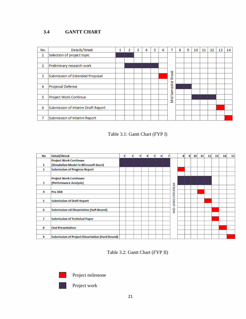
3.4 GANTT CHART
Table 3.1: Gantt Chart (FYP I)
Table 3.2: Gantt Chart (FYP II)
Project milestone
Project work
22
CHAPTER 4
RESULT AND DISCUSSION
4.1 SIMULATION RESULT AND DISCUSSION
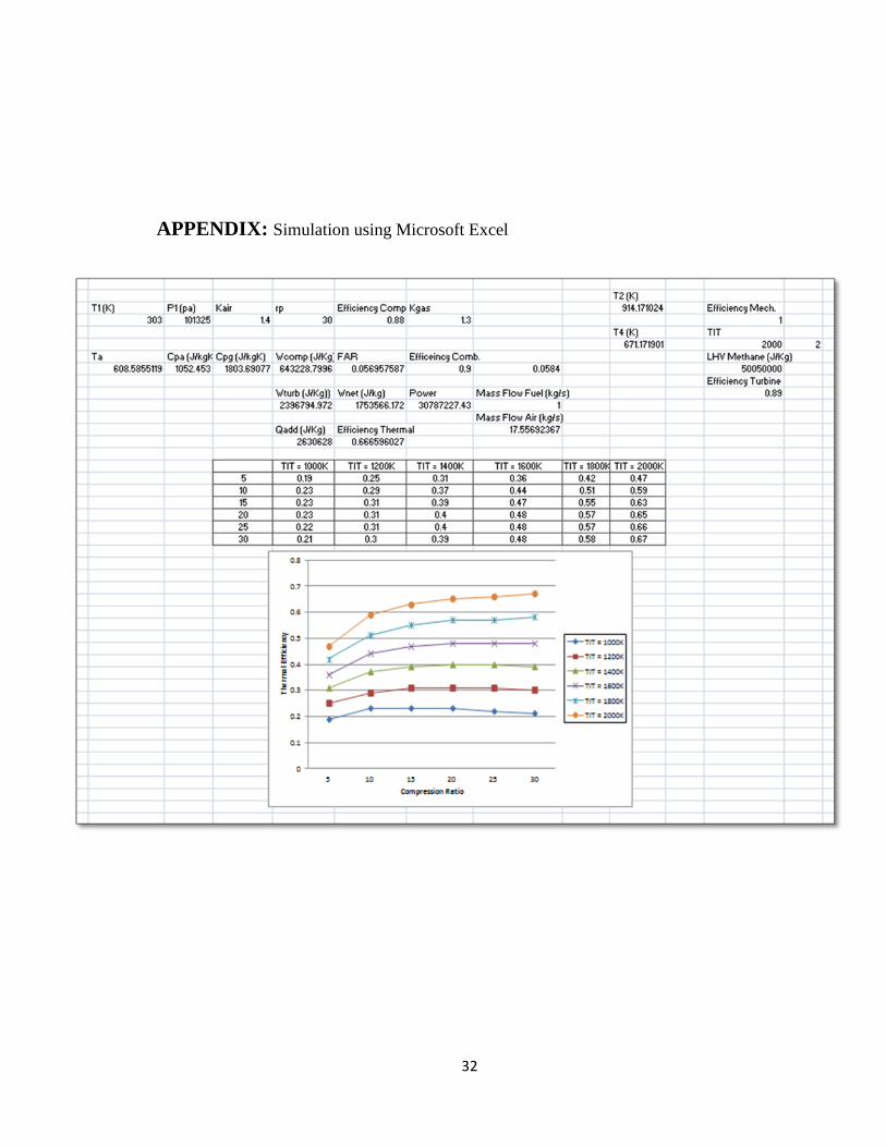
Figure 4.1 (a) presents a relation between the gas turbine cycle thermal efficiency versus
compression ratios for different turbine inlet temperature (TIT). Based on the simulation
result represented in graph, thermal efficiency increases with respect to the higher
compression ratio and higher turbine inlet temperature (TIT). At lower compression ratio,
the deviation of thermal efficiency is not significant but the variation at higher
compression ratio is vital for thermal efficiency at different turbine inlet temperature
(TIT). Furthermore, at lower turbine inlet temperature, the efficiency will be increase at
one point, and then it will start dropping when the compression ratio increases. From the
equation of work net of turbine, when turbine inlet temperature (TIT) increase work net
of turbine also will increase hence it produce higher power output. So, thermal efficiency
of the system will increase.
Figure 4.1 (b) presents a relation between the gas turbine cycle thermal efficiency versus
compression ratio for different ambient temperature. Thermal efficiency increase with
increase the compression ratio and decrease in ambient temperature. Thermal efficiency
is affected by ambient temperature due to the change of air density. Lower ambient
temperature leads to a higher air density and reduce work of the compressor. So, lower
compressor work will tends to increase gas turbine power output and thermal efficiency

23
will be increase. The increase of ambient temperature leads to decrease of the thermal
efficiency.
(a) Turbine Inlet Temperature (TIT)
(b) Ambient Temperature
Figure 4.1: Variation of compression ratio, turbine inlet temperature (TIT) and ambient
temperature on thermal efficiency

24
Figure 4.2 show the relationship between thermal efficiency and compression ratio at
different fuel to air ratio. Thermal efficiency increase with increase the compression ratio
and increase in fuel to air ratio (FAR). The variation of thermal efficiency for different
fuel to air ratio (FAR) at low compression ratio is not much but at higher compression
ratio the variation of thermal efficiency is greater. Higher fuel to air ratio (FAR) will tend
to encourage combustion in combustion chamber then will produce higher temperature of
flue gas that will be expand in turbine. Hence it will increase thermal efficiency of the
gas turbine.
Figure 4.2: Variation of compression ratio and fuel to air ratio (FAR) on thermal
efficiency

25
Figure 4.3 present the effect of compression ratio on compressor work. Compressor work
increases with increase the compression ratio and the ambient temperature. Furthermore,
at lower compression ratio for different ambient temperature, the variations of
compressor work are not significance but at higher compression ratio, the variations of
compressor work are more significance. Thermal efficiency is affected by ambient
temperature due to the change of air density. Higher ambient temperature leads to a lower
air density and increase work of the compressor. So, higher compressor work will tends
to decrease gas turbine power output and thermal efficiency will also been decrease.
Figure 4.3: Effect of compression ratio and ambient temperature on compressor work

26
Figure 4.4 shows that the gas turbine thermal efficiency decreases when ambient
temperature increase. This is because the air mass flow rate inlet to compressor increases
with decrease of the ambient temperature. So the fuel mass flow rate will increase, since
fuel to air ratio (FAR) is keep constant. The slope for decreasing is stiffer for higher fuel
to air ratio (FAR).
Figure 4.4: Effect of ambient temperature and fuel to air ratio (FAR) on thermal
efficiency

27
Figure 4.5 presents the relationship between shaft powers of gas turbine with respect to
ambient temperature at different fuel to air ratio (FAR). Power decrease with increase of
ambient temperature and decrease in fuel to air ratio (FAR). At lower ambient
temperature, the air draws by compressor is high in density and lower the compressor
work. So, this will yield the higher gas turbine output power. The decreasing in term of
output power is more significant with higher fuel to air ratio (FAR).
Figure 4.5: Effect of ambient temperature and fuel to air ratio (FAR) on power

28
CHAPTER 5
CONCLUSION AND RECOMMENDATION
5.1 CONCLUSION
Based on the performance analysis from the graph of the simulation result, there are two
significant finding that affect performance of gas turbine
1) The compression ratios, ambient temperature, fuel to air ratio and turbine inlet
temperature strongly influence the thermal efficiency of the gas turbine.
2) At higher turbine inlet temperature (TIT), compression ratio and lower ambient
temperature (T1), thermal efficiency increase hence the output power of the gas
turbine will be higher.
Studies on gas turbine are being carried out quite extensively to find suitable parameters
that meet the highest possible thermal efficiency and also desire power output. This deals
with wide area of interest including industrial applications and power generation unit.
This project was mainly about parametric analysis for gas turbine application. Simulation
model was established in Microsoft Excel environment and analysis of the performance
of gas turbine was placed once the simulation was done. At the end of this study, the
combined parameters that give optimum gas turbine performance for a given conditions
was suggested.

29
5.2 RECOMMENDATION
Due to the time limitation and limited access to the real operating data from installed gas
turbine at plant, this project only focus on several operating parameter which are ambient
temperature, turbine inlet temperature, fuel to air ratio and compression ratio. Then, the
operating parameters were varied and the effect to the performance of gas turbine was
studied.
For extended study, I am proposing that the other operating parameter such as efficiency
of compressor and turbine also might be considered to determine the performance of the
gas turbine. Beside, real operating data might be extracted from any plant that have gas
turbine in service, so less assumption and more accurate result can be get from the study.
Analysis on simple gas turbine might yield close to the ideal result but for further study,
more advance gas turbine could be analyzing so that the result will be more reliable in the
future.
Using other software like C++ or MATLAB to do analysis or develop friendly user
interface software using visual basic to make the project usable for any parties.
Developed software might be use by engineer in the plant to predict the performance of
the gas turbine in their plant. It might reduce time consumption to anticipate gas turbine
problem and save cost instead.

30
REFERENCES
1. Anders Hellberg (2010) SGT-750 – 37MW Gas Turbine, 19th Symposium of The
Industrial Application of Gas Turbines Committee, Siemens Industrial Turbo
machinery
2. Cengel, A.Y. and Boles, A.M. 2008. Thermodynamics an engineering approach.
New York: McGraw-Hill.
3. Horlock JH (2003). Advance Gas Turbine Cycles. Elsevier Sci. Ltd., UK.
4. Ibrahim TK, Rahman MM, Alla AN (2010). Study on the effective parameter of
gas turbine model with intercooled compression process. Sci. Res. Essays, 5(23):
3760-3770.
5. Kakaras E, Doukelis A, Karellas S (2004). Compressor intake-air cooling in gas
turbine plants. Energy, 29: 2347-2358.
6. M.M Rahman, Thamir K. Rahman and Ahmed N. Abdalla (2011)
Thermodynamic Performance Analysis of Gas Turbine Power Plant, International
Journal of the Physical Sciences Vol. 6(14), pp. 3539-3550, 18 July, 2011
Available online at http://www.academicjournals.org/IJPS
7. Mahmood, F.G. and Mahdi, D.D. 2009. A new approach for enhancing
performance of a gas turbine (Case study: Khangiran Refinery). Applied Energy,
86: 2750–2759.
8. Mahmoudi SM, Zare V, Ranjbar F, Farshi L (2009). Energy and exergy analysis
of simple and regenerative gas turbines inlet air cooling using absorption
refrigeration. J. Appl. Sci., 9(13): 2399-2407.
9. Nag, P.K. 2008. Power plant engineering. New Delhi: Tata McGraw-Hill
Publishing Company Limited
10. Naradasu RK, Konijeti RK, Alluru VR (2007). Thermodynamic analysis of heat
recovery steam generator in combined cycle power plant.Therm. Sci., 11(4): 143-
156
11. Saravanamuttoo H, Rogers G, Cohen H, Straznicky P (2009). GasTurbine Theory.
Prentice Hall, ISBN 978-0-13-222437-6

31
12. Sadrameli SM, Goswami DY (2007). Optimum operating conditions for a
combined power and cooling thermodynamic cycle. Appl. Ener., 84: 254-265.
13. Taniquchi, H. and Miyamae, S. 2000. Power generation analysis for high
temperature gas turbine in thermodynamic process. Journal of Propulsion and
Power, 16: 557-561.
14. Wang, F.J. and Chiou, J.S. 2002. Performance improvement for a simple cycle
gas turbine GENSET-a retrofitting example. Applied Thermal Engineering, 22:
1105–1115
15. Xiaojun S, Brian A, Defu C, Jianmin G (2010). Performance enhancement of
conventional combined cycle power plant by inlet aircooling, inter-cooling and
LNG cold energy utilization. Appl. Ther. Eng., 30: 2003-2010.
16. Zurcher U, Badoux JC, Mussard M (1988). The world’s first industrial gas turbine
set at Neuchatel. An International Historic Mechanical Engineering Significance
of Landmark, September 2, Neuchatel Switzerland, ASME
32
APPENDIX: Simulation using Microsoft Excel


![Thermodynamic Performance Analysis of a Gas Turbine in …file.scirp.org/pdf/JPEE_2015010910334938.pdf · of a (25MW) gas turbine power plant modeled with a spr ay cooler [10]. ...](https://static.fdocuments.in/doc/165x107/5a7600047f8b9a1b688cdfdf/thermodynamic-performance-analysis-of-a-gas-turbine-in-filescirporgpdfjpee.jpg)