
ThermoDual®- FLS-COMI · ThermoDual®- FLS-COMI Data sheet General description/ Application...
4
© Danfoss | 2018.01 VD.LZ.H1.02 | 1 ThermoDual®- FLS-COMBI Data sheet General description/ Application Domestic hot water provision by instantaneous heater is an efficient and hygienic optimal solution. Hot water is not stored and will be produced only on request. Thus, low temperatures in drinking water can be reduced to a necessary minimum. Habitats for bacteria,such as legionella are virtually non- existent. If the conditions for connection of these systems are given (sufficiently high capacity on heating side to cover peak load) or buffer tanks is present, these systems can be used unrestricted. Significant advantages of the system are: • no storage of drinking water • efficient cooling of the primary media • optimum use of energy • independent choice of different energy sources • at any time sufficiently high domestic hot water temperature, that fulfils all hygienic requirements • low space requirement • lime scale is largely avoided Maximum operating parameters Primary Maximum permissible supply temperature, primary 90°C Maximum permissible operating pressure, primary 10 bar(g) Rated pressure, primary PN10 Secondary Maximum permissible temperature, secondary 90°C Maximum permissible operating pressure, secondary 10 bar(g) Minimum required pressure (static), water supply 1,0 bar(g) Rated pressure, secondary PN10 Mains power supply / maximum power consumption 230V AC / 4,0 A Materials Pipes, fittings, flanges, valves (domestic side) 1.4571, bronze or brass as per DIN EN 1982, also considering DIN 50930-06 and UBA guidelines ditto (heating side) P235GH-TC1, CuSn5Pb5Zn5-C (RG-5), ST37.0 Heat exchanger 1.4404 with Cu solder Insulation Hardcover EPP λ=0.036 W/mK (100%ENEV) Code numbers Capacity [kW] Code no. Pump control (PWM control signal) 70 004X1538 130 004X1539 175 004X1540
Transcript of ThermoDual®- FLS-COMI · ThermoDual®- FLS-COMI Data sheet General description/ Application...

© Danfoss | 2018.01 VD.LZ.H1.02 | 1
ThermoDual®- FLS-COMBIData sheet
General description/ Application
Domestic hot water provision by instantaneous heater is an efficient and hygienic optimal solution. Hot water is not stored and will be produced only on request. Thus, low temperatures in drinking water can be reduced to a necessary minimum.Habitats for bacteria,such as legionella are virtually non-existent. If the conditions for connection of these systems are given (sufficiently high capacity on heating side to cover peak load) or buffer tanks is present, these systems can be used unrestricted. Significant advantages of the system are:• no storage of drinking water• efficient cooling of the primary media• optimum use of energy• independent choice of different energy sources• at any time sufficiently high domestic hot water temperature, that fulfils all hygienic requirements• low space requirement• lime scale is largely avoided
Maximum operatingparameters
PrimaryMaximum permissible supply temperature, primary 90°CMaximum permissible operating pressure, primary 10 bar(g)Rated pressure, primary PN10SecondaryMaximum permissible temperature, secondary 90°CMaximum permissible operating pressure, secondary 10 bar(g)
Minimum required pressure (static), water supply 1,0 bar(g)
Rated pressure, secondary PN10Mains power supply / maximum power consumption 230V AC / 4,0 A
MaterialsPipes, fittings, flanges, valves (domestic side) 1.4571, bronze or brass as per DIN EN 1982,
also considering DIN 50930-06 and UBA guidelinesditto (heating side) P235GH-TC1, CuSn5Pb5Zn5-C (RG-5), ST37.0Heat exchanger 1.4404 with Cu solderInsulation Hardcover EPP λ=0.036 W/mK (100%ENEV)
Code numbersCapacity
[kW]
Code no.Pump control
(PWM control signal)70 004X1538
130 004X1539175 004X1540
VDLZH102_ThermoDual-FLS-COMBI_180110.indd 1 2018-01-10 13:08:55
Data sheet ThermoDual®- FLS-COMBI
2 | © Danfoss | 2018.01 VD.LZ.H1.02
Technical dataTyp
ThermoDual®Capacity
[kW]
FRp
(70->25°C)[m3/h]
Pump dpr
[kPa]
FRDW
(10->60°C)[m3/h]
DWdp
[kPa]
FRC
(55->60°C)[m3/h]
Cdpr*[kPa]
FLS-COMBI 70 70 1,34 55 1,2 15 1,0 20
FLS-COMBI 130 130 2,5 35 2,23 25 1,5 35
FLS-COMBI 175 175 3,35 25 3,0 24 2,0 25
FR: Flow rate p: primary dpr: Remaining pump head dp: Pressure loss DW: Domestic water C: Circulation * (maximal possible)
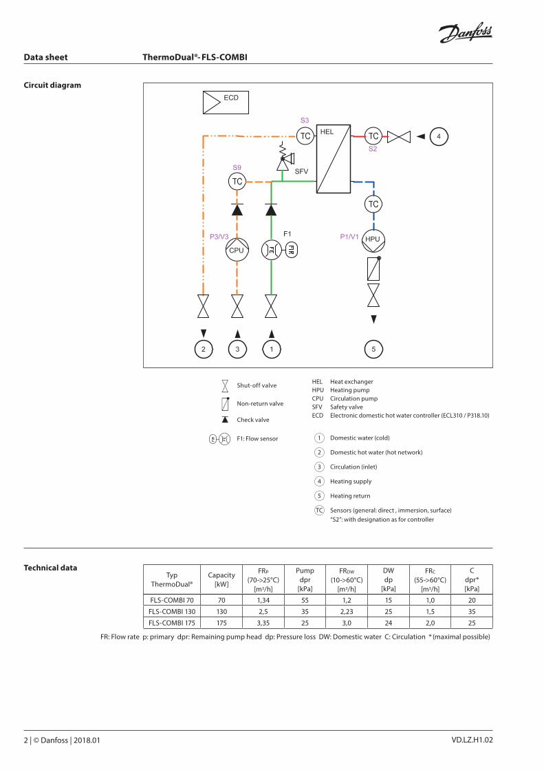
Circuit diagram
HEL Heat exchangerHPU Heating pumpCPU Circulation pumpSFV Safety valveECD Electronic domestic hot water controller (ECL310 / P318.10)
1 Domestic water (cold)
2 Domestic hot water (hot network)
3 Circulation (inlet)
4 Heating supply
5 Heating return
TC Sensors (general: direct , immersion, surface)“S2”: with designation as for controller
Shut-off valve
Non-return valve
Check valve
F1: Flow sensor
VDLZH102_ThermoDual-FLS-COMBI_180110.indd 2 2018-01-10 13:08:56

Data sheet ThermoDual®- FLS-COMBI
© Danfoss | 2018.01 | 3VD.LZ.H1.02
Function Flow systems provide heated domestic water when requested. By a heat exchanger (HEL), the cold water flowing into connection (1) will be heated up to set point and provided to the consumer at the connection (2). The electronic controller (ECD) is measuring the relevant temperatures and controls the target values that are held constant in all operating conditions. This is i.e. achieved by influencing the speed of the heating pump (HPU), so that the outlet temperature always matches the specified value. Short-term peaks in consumption are registered at the flow sensor to intervene quickly and avoid large temperature fluctuations. The cooled- circulation water from the network (connection 3) is constantly heated in heat exchanger (HEL), even in times of draw-off , reheated and the temperature control (sensor) in the amount of the controlled circulation pump (CPU) influenced so that only the necessary amount flows to maintain constant power set point.The capacity for the peak load is to ensure either by buffering heating water in a tank (BTA) or there must be a sufficiently large connection value available. The Recharging of a buffer (e.g. from a boiler) can a requisition (sensor / switch contact) on controller (ECD) using an on-site charging pump (LPU). The operation of the system by a controlled heating pump (HPU) is only possible without differential pressure between the connections (4) and (5).
Dimensions
TypeThermoDual®
Connections
H1 [mm]
H2 [mm]
H3 [mm]
Weight [ kg]
DW C/H Circ.HTG (DN)
SL, RL Pumpcontrol(PWM)1/2
G ISO3
G ISO4/5 PN10
RpFLS-COMBI 70 1" I 1" I 1 ¼” 90 90 70 31
FLS-COMBI 130 1" I 1" I 1 ¼” 90 90 70 34FLS-COMBI 175 1 ¼" I 1" I 1 ¼” 105 90 96 36
876
521275
H3
H2
H1
115 155 155 275
700
298
2
4
3 1 5
VDLZH102_ThermoDual-FLS-COMBI_180110.indd 3 2018-01-10 13:08:56

VD.LZ.H1.024 | © Danfoss | DHS-SMT/PL | 2018.01
Datenblatt ThermoDual®- FLS-COMBI
Accessories Heating buffer storage tank, standing model, Charging-/Discharging Connections as flange connection Type: PSS
Pipe set for simple connection between system and buffer
System Buffer Pipe set Dimensions
Type Code Type Volume [l] Code Type Code H1 [mm] H2 [mm] H3 [mm] L [mm]
FLS-Combi 70 004X1538 PSS 300 300 640U4984 FLS 70 + PSS 300 146B2450 1450 265 1923 1515
FLS-Combi 70 004X1538 PSS 500 500 640U4985 FLS 70/130 + PSS 500 146B2451 1860 325 2024 1625
FLS-Combi 130 004X1539 PSS 500 500 640U4985 FLS 70/130 + PSS 500 146B2451 1860 325 2024 1625
FLS-Combi 130 004X1539 PSS 750 750 640U4986 FLS 130 + PSS 750 146B2452 1870 325 2024 1775
FLS-Combi 175 004X1540 PSS 750 750 640U4986 FLS 175+ PSS 750 146B2453 1870 325 2063 1775
FLS-Combi 175 004X1540 PSS 1000 1000 640U4987 FLS 175 + PSS 1000 146B2454 1910 345 2095 1892
200H2
742
1618
H1
H3
L
VDLZH102_ThermoDual-FLS-COMBI_180110.indd 4 2018-01-10 13:09:01