
Thermocouples and RTD - ZRE · Thermocouple and RTD 2 Thermocouple are components used for...
18
MODEL Z.22 Thermocouples and RTD ... Infinite solutions ...
Transcript of Thermocouples and RTD - ZRE · Thermocouple and RTD 2 Thermocouple are components used for...

MODEL Z.22
Thermocouples and RTD
... Infinite solutions ...

Thermocouple and RTD
2
Thermocouple are components used for temperaturecontrol. A thermocouple is composed by two differentmetal conductors joined at one end and encapsulatedin a metallic tube. As the temperature changes, the vol-tage reading at the end of the conductors changes toopermitting to measure the temperature on the junction.
There are three different way to join the conductors:
l Insulated thermocouples
The measuring junction is not in contact with the
external sheath. This solution guarantee a good pro-
tection from parasitic currents generated by magne-tic
fields or any other equipment.
Insulated thermocouples are a good balance bet-
ween protection against interferences and response
time.
l Grounded thermocouples
The measuring junction is sealed together with the
external protection. This solution guarantee a high
response time but due to the grounded junction it
may suffer interference on the output signal.
l Exposed junction
The measuring junction is exposed to the atmosphere
on the measuring area. being equal the external she-
ath diameter this solution guarantee the best respon-
se time. It is not suitable for measurements at high
temperatures and in aggressive environments
For further info please, contact our technical dep.
We reserve the right to change technical details.
Model Z.22thermocouples
Technical features
Model Z.22
Application: ...........................................+ Article number (if knows): ................+ Diameter: ..........................................+ Length (L): ........................................+ Grounded or insulated: ....................+ Leads length (L2):.............................+ Leads type: ......................................+ Quantity: ...........................................+ Any connection: ...............................
How
to order
Insulated thermocouples
Grounded thermocouples
Exposed junction

3
Thermocouple and RTD
Technical features
Comparative analysis of performances
Response time Vibration strength Resistance to com-pressive stress
Durability
MgoCalibratedwires andinsulators
Construction
Two ways may be used to construct a thermocouple:l MgO insulated
Those kind of thermocouples are made with Magnesium Oxide insulated leads.
Those leads are composed by a metallic external sheath in which the two metal
conductors are insulated from each others and from the outer sheath with com-
pressed MgO powder. MgO insulated thermocouples are rugged sensors that
guarantee much higher performance than those constructed using the classical
method together with high shock resistance and vibrations resistance.
They can also be bent in order to adapt them to different application.
Response time, possibility of miniaturization and long lifespan are other particular
characteristics of the mineral insulated sensors.
l With calibrated wires and insulators
The wires are insulated by an external rigid sheath using ceramic insulators
The outside sheath must provide suitable protection of the wires against gases
or corrosive agents that may be present in the measurement environment.
Selection of the wires of suitable diameter and type according to the type of
wor-
king environment is also important.
The suitable insulation (ceramic or fibreglass insulation) has to be indentified
according to the working temperature.
ThermocoupleThermocouple
Protection sheath Protection sheath
Magnesium oxide powderMagnesium oxide powder
ThermocoupleThermocouple
Protection sheath Protection sheath
InsulatorInsulator
MgoCalibratedwires andinsulators
MgoCalibratedwires andinsulators
MgoCalibratedwires andinsulators
4
Thermocouple and RTD
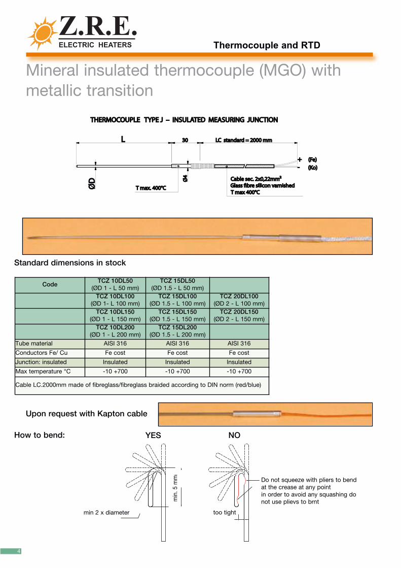
Mineral insulated thermocouple (MGO) withmetallic transition
Upon request with Kapton cable
CodeTCZ 10DL50
(ØD 1 - L 50 mm)TCZ 15DL50
(ØD 1.5 - L 50 mm)TCZ 10DL100
(ØD 1- L 100 mm)TCZ 15DL100
(ØD 1.5 - L 100 mm)TCZ 20DL100
(ØD 2 - L 100 mm)TCZ 10DL150
(ØD 1 - L 150 mm)TCZ 15DL150
(ØD 1.5 - L 150 mm)TCZ 20DL150
(ØD 2 - L 150 mm)TCZ 10DL200
(ØD 1 - L 200 mm)TCZ 15DL200
(ØD 1.5 - L 200 mm)Tube material AISI 316 AISI 316 AISI 316
Conductors Fe/ Cu Fe cost Fe cost Fe cost
Junction: insulated Insulated Insulated Insulated
Max temperature °C -10 +700 -10 +700 -10 +700
Cable LC.2000mm made of fibreglass/fibreglass braided according to DIN norm (red/blue)
ØD
ØD Ø
4Ø
4
LL 3030 LC standard = 2000 mmLC standard = 2000 mm
THERMOCOUPLE TYPE J – INSULATED MEASURING JUNCTIONTHERMOCOUPLE TYPE J – INSULATED MEASURING JUNCTION
T max. 400°CT max. 400°C
Cable sec. 2x0,22mm2Cable sec. 2x0,22mm2Glass #bre silicon varnishedGlass #bre silicon varnishedT max 400°CT max 400°C
+ + (Fe)(Fe)- - (Ko)(Ko)
Standard dimensions in stock
How to bend: YES NO
Do not squeeze with pliers to bendat the crease at any pointin order to avoid any squashing donot use plievs to brntm
in. 5
mm
i
min 2 x diameter too tight
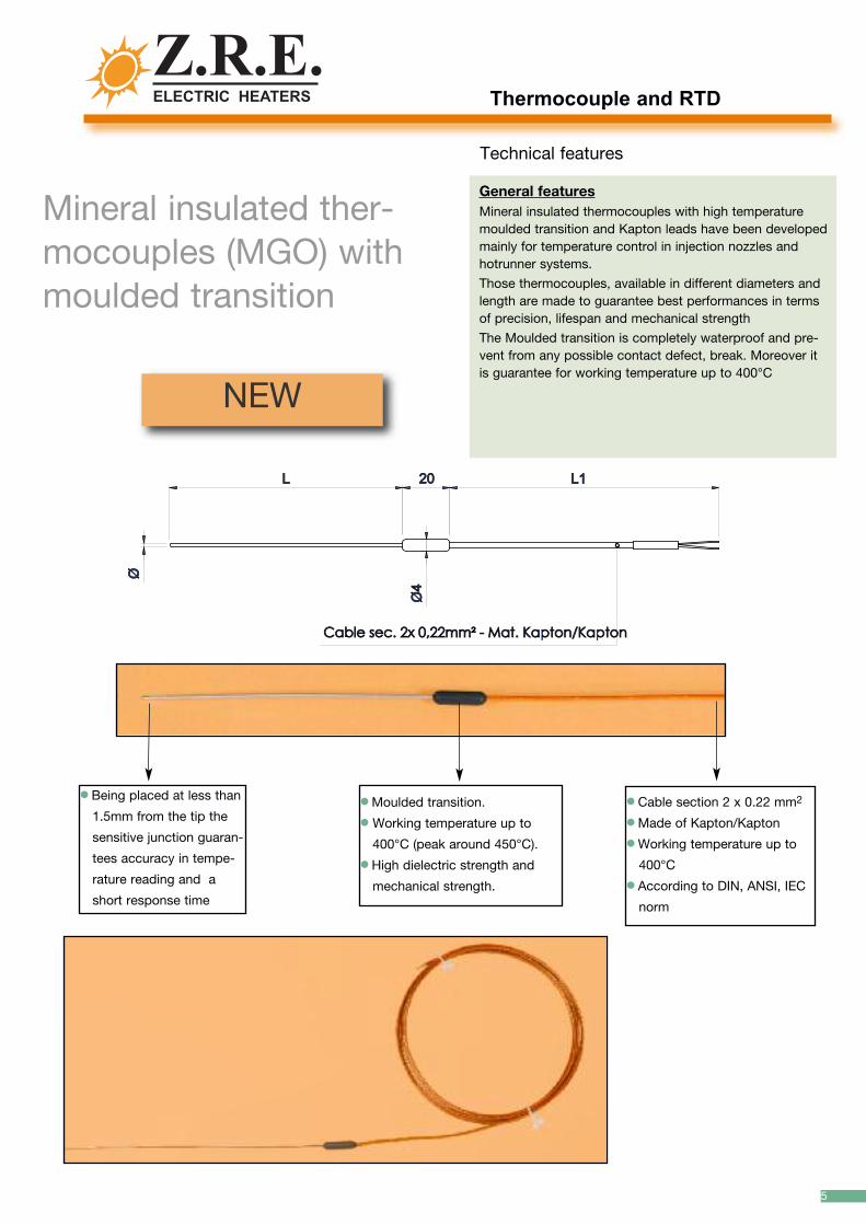
General featuresMineral insulated thermocouples with high temperaturemoulded transition and Kapton leads have been developedmainly for temperature control in injection nozzles andhotrunner systems.
Those thermocouples, available in different diameters andlength are made to guarantee best performances in termsof precision, lifespan and mechanical strength
The Moulded transition is completely waterproof and pre-vent from any possible contact defect, break. Moreover itis guarantee for working temperature up to 400°C
Mineral insulated ther-mocouples (MGO) withmoulded transition
Technical features
Thermocouple and RTD
5
NEW
l Being placed at less than
1.5mm from the tip the
sensitive junction guaran-
tees accuracy in tempe-
rature reading and a
short response time
l Moulded transition.
l Working temperature up to
400°C (peak around 450°C).
l High dielectric strength and
mechanical strength.
l Cable section 2 x 0.22 mm2
l Made of Kapton/Kapton
l Working temperature up to
400°C
l According to DIN, ANSI, IEC
norm
ØØ
Ø4
Ø4
Cable sec. 2x 0,22mm² - Mat. Kapton/KaptonCable sec. 2x 0,22mm² - Mat. Kapton/Kapton
LL 2020 L1 L1

Thermocouple and RTD
Code TCZ 3010P
Foil material Brass
Conductors material Fe cost
Measuring junction Grounded
max Temperature °C -10 +400
Cable L.2000 mm v.sil/v.sil sch(*)
Code TCZ 3030P
Tube material AISI 304
Foil material Brass
Conductors material Fe cost
Measuring junction Grounded
max Temperature °C -10 +400
Cable L.2000 mm v.sil/v.sil sch(*)
6
�8�8
3030
0.50.5
3030
5050 L=2000L=2000
L=2000L=20000.50.5 3030
1010
Code TCZ4025P
Tube material AISI304
Conductors material Fe cost
Measuring junction Grounded
max Temperature °C -10 +400
Cable L.2000 mm v.sil/v.sil sch(*)
2525
66
L=2000L=2000
66
11
2.52.5
Thermocouple standard in stock

Thermocouple and RTD
7
Code TCZ 5D10DS
Eyelet Copper
Conductors material Fe cost
Measuring junction Grounded
max Temperature.°c -10 +400
Cable L.2000 mm Vetrotex
L=2000L=2000
�10
�10
�5
�5
88
Code TCZ 5D10D
Eyelet AISI 304
Conductors material Fe cost
Measuring junction Grounded
max Temperature °C -10 +400
Cable L.2000 mm v.sil/v.sil sch(*)
L=2000L=2000
�10
�10
�5
�5
88
Code Z22R005010
Conductors material Fe cost
Measuring junction Grounded
max Temperature.°c -10 +400
Cable L.2000 mm v.sil/v.sil sch(*)
L=2000L=20002121
Ø10Ø10
Ø5Ø5
10
10
5 5
44
7070
Thermocouple and RTD
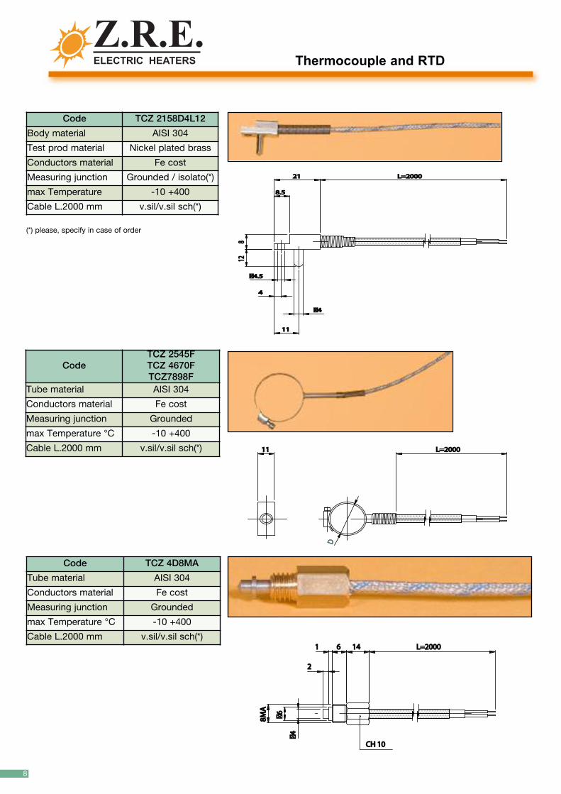
CodeTCZ 2545FTCZ 4670FTCZ7898F
Tube material AISI 304
Conductors material Fe cost
Measuring junction Grounded
max Temperature °C -10 +400
Cable L.2000 mm v.sil/v.sil sch(*)
Code TCZ 4D8MA
Tube material AISI 304
Conductors material Fe cost
Measuring junction Grounded
max Temperature °C -10 +400
Cable L.2000 mm v.sil/v.sil sch(*)
8
Code TCZ 2158D4L12
Body material AISI 304
Test prod material Nickel plated brass
Conductors material Fe cost
Measuring junction Grounded / isolato(*)
max Temperature -10 +400
Cable L.2000 mm v.sil/v.sil sch(*)
2121
8.58.5
44
�4.5 �4.5
1111
�4�4
881212
L=2000L=2000
L=2000L=20001111
DD
8MA
8M
A
�6
�6
�4
�4
66 141411
22
L=2000L=2000
CH 10CH 10
(*) please, specify in case of order
Thermocouple and RTD
9
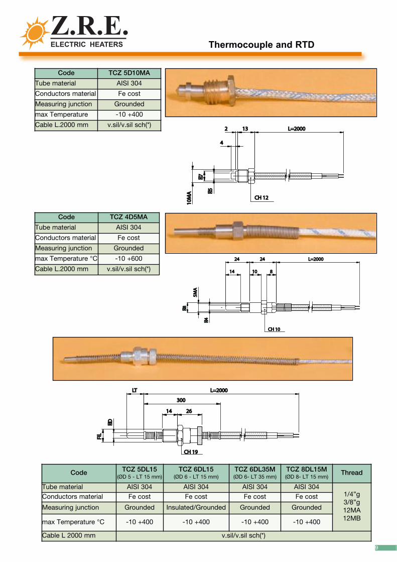
Code TCZ 5DL15(ØD 5 - LT 15 mm)
TCZ 6DL15(ØD 6 - LT 15 mm)
TCZ 6DL35M(ØD 6- LT 35 mm)
TCZ 8DL15M(ØD 8- LT 15 mm)
Thread
Tube material AISI 304 AISI 304 AISI 304 AISI 3041/4”g3/8”g12MA12MB
Conductors material Fe cost Fe cost Fe cost Fe cost
Measuring junction Grounded Insulated/Grounded Grounded Grounded
max Temperature °C -10 +400 -10 +400 -10 +400 -10 +400
Cable L 2000 mm v.sil/v.sil sch(*)
1414 2626
300300
L=2000L=2000LTLT
Fil.
Fil.
�D
�D
CH 19CH 19
Code TCZ 4D5MA
Tube material AISI 304
Conductors material Fe cost
Measuring junction Grounded
max Temperature °C -10 +600
Cable L.2000 mm v.sil/v.sil sch(*)
5MA
5MA
�8
�8
�4
�4
2424
1414
2424
1010 88
L=2000L=2000
CH 10CH 10
Code TCZ 5D10MA
Tube material AISI 304
Conductors material Fe cost
Measuring junction Grounded
max Temperature -10 +400
Cable L.2000 mm v.sil/v.sil sch(*)
10M
A
10M
A
�7
�7
�5
�5
22
44
L=2000L=2000
CH 12CH 12
1313
Thermocouple and RTD
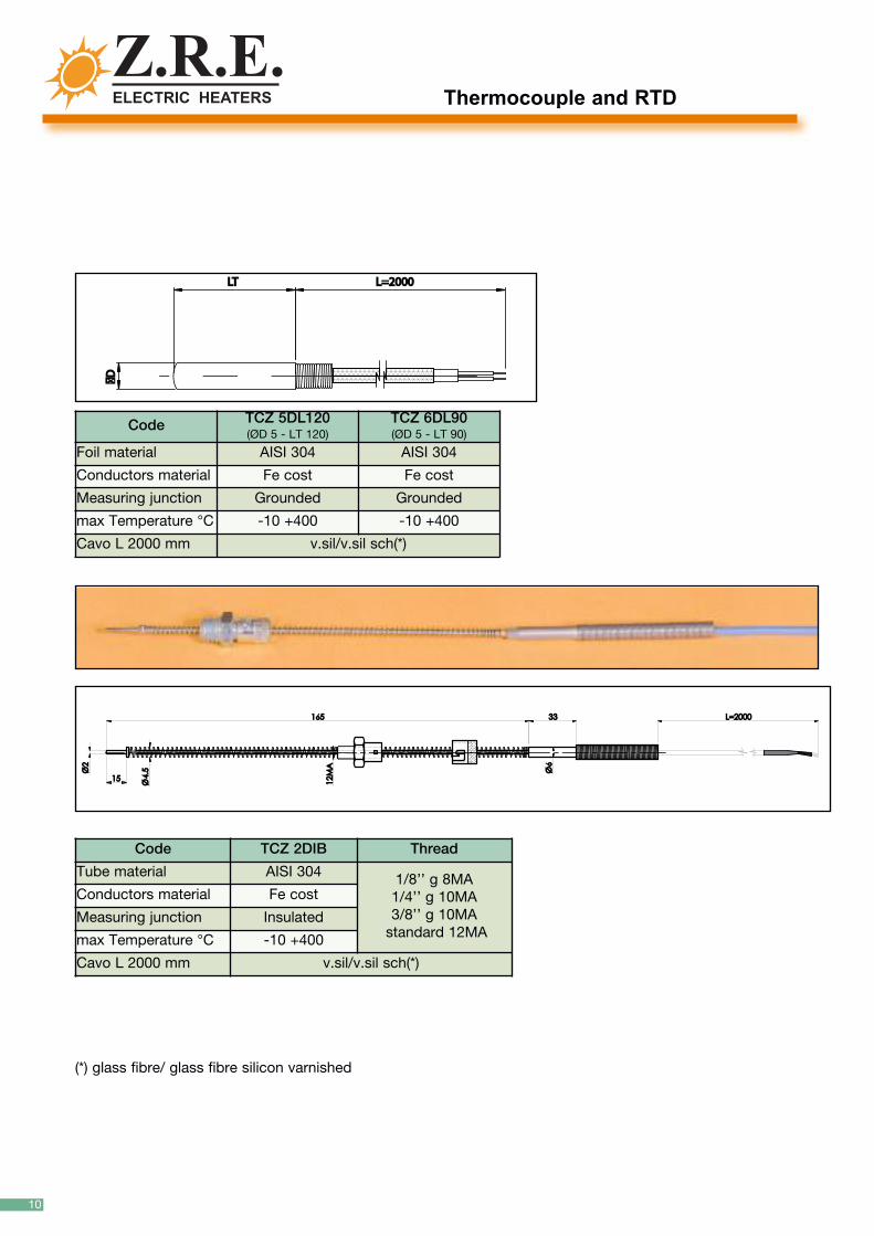
Code TCZ 2DIB Thread
Tube material AISI 304 1/8’’ g 8MA1/4’’ g 10MA3/8’’ g 10MAstandard 12MA
Conductors material Fe cost
Measuring junction Insulated
max Temperature °C -10 +400
Cavo L 2000 mm v.sil/v.sil sch(*)
10
Code TCZ 5DL120(ØD 5 - LT 120)
TCZ 6DL90(ØD 5 - LT 90)
Foil material AISI 304 AISI 304
Conductors material Fe cost Fe cost
Measuring junction Grounded Grounded
max Temperature °C -10 +400 -10 +400
Cavo L 2000 mm v.sil/v.sil sch(*)
�D
�D
LTLT L=2000L=2000
165165
1515
Ø2
Ø2
12MA
12MA
Ø4.5
Ø4.5 Ø6
Ø6
3333 L=2000L=2000
(*) glass fibre/ glass fibre silicon varnished
Thermocouple and RTD
11
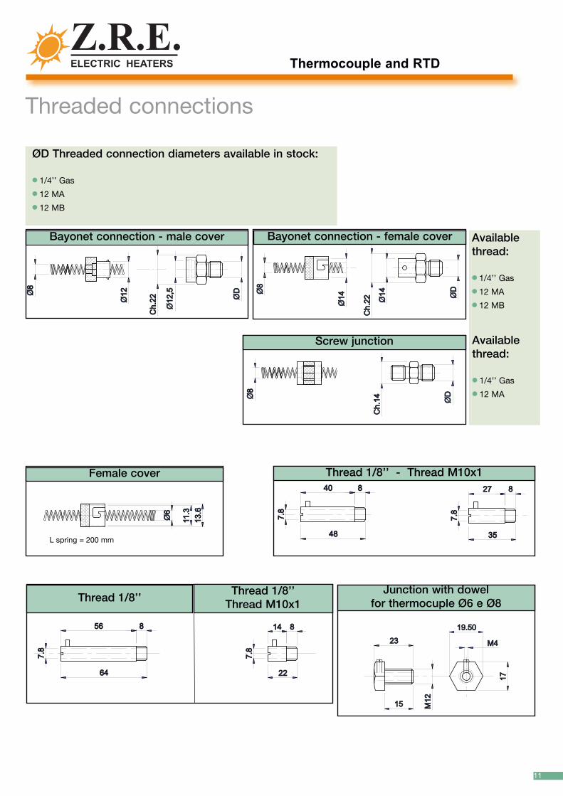
Threaded connections Ø12
Ø12
Ø12,5
Ø12,5
Ch.22
Ch.22
Ø8
Ø8
ØD
ØD
Bayonet connection - male cover
Ø14
Ø14
Ø14
Ø14
Ch.22
Ch.22
Ø8
Ø8
ØD
ØD
Bayonet connection - female cover
Ch.14
Ch.14Ø8
Ø8
ØD
ØD
Screw junction
1717
M4M4
M12
M12
19.5019.50
1515
2323
Junction with dowel for thermocuple Ø6 e Ø8
35354848
7.8
7.8
7.8
7.8
2727 884040 88
Ø6
Ø6
13.6
13.6
11.3
11.3
Thread 1/8’’ - Thread M10x1Female cover
22226464
7.8
7.8
1414 885656 88
7.8
7.8
Thread 1/8’’Thread 1/8’’Thread M10x1
ØD Threaded connection diameters available in stock:
l 1/4’’ Gas
l 12 MA
l 12 MB
Availablethread:
l 1/4’’ Gas
l 12 MA
l 12 MB
Availablethread:
l 1/4’’ Gas
l 12 MA
L spring = 200 mm
Thermocouple and RTD
12
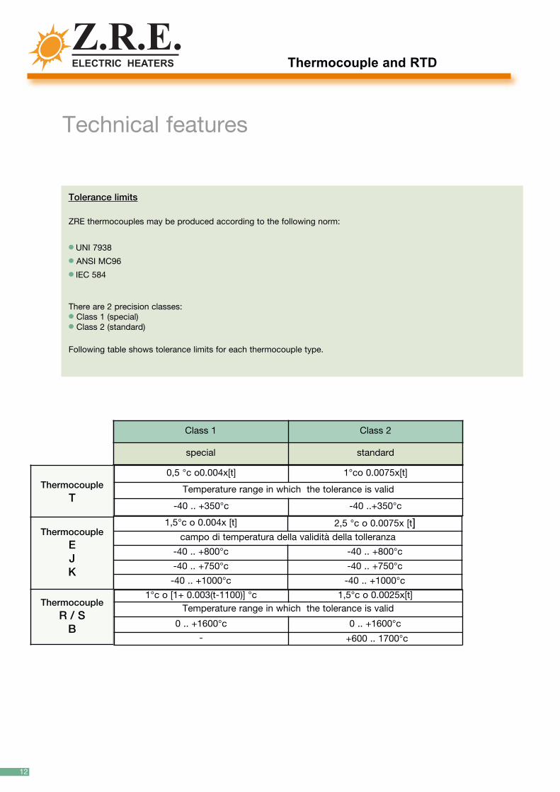
Technical features
Tolerance limits
ZRE thermocouples may be produced according to the following norm:
l UNI 7938
l ANSI MC96
l IEC 584
There are 2 precision classes:l Class 1 (special)l Class 2 (standard)
Following table shows tolerance limits for each thermocouple type.
Class 1 Class 2
special standard
ThermocoupleT
ThermocoupleEJK
ThermocoupleR / SB
0,5 °c o0.004x[t] 1°co 0.0075x[t]
Temperature range in which the tolerance is valid
-40 .. +350°c -40 ..+350°c
1,5°c o 0.004x [t] 2,5 °c o 0.0075x [t]campo di temperatura della validità della tolleranza
-40 .. +800°c -40 .. +800°c
-40 .. +750°c -40 .. +750°c
-40 .. +1000°c -40 .. +1000°c
1°c o [1+ 0.003(t-1100)] °c 1,5°c o 0.0025x[t]Temperature range in which the tolerance is valid
0 .. +1600°c 0 .. +1600°c
- +600 .. 1700°c

Thermocouple and RTD
13
Temperature
rang
e
(c°)
IEC 584_3
(Europ
ean)
ANSI
(USA,Can
ada)
DIN43710
(German
y -
Holland
)
BS1843
(U.K-
Czech
rep
ublic)
NFE 18001
(Franc
e)
JIS 1610-
1981
(Jap
an)
TCop
per+
copper-nikel
-270
/+40
0
JIron
+co
pper-nikel-
-200
/+76
0
Enich
el-chrom
e+co
pper-nikel-
-270
/+10
00
Knike
l-ch
rome+
nich
el-alluminium-
-270
/+13
72
Nnike
l-ch
rome-silicon
+nike
l-silicon
-
-270
/+13
00
SeR
platin
um-rho
dium+
platin
um-
-50/17
68
Bplatin
um30
%-rho
dium+
platin
um-
0/18
20
International thermocouples colour code

Thermocouple and RTD
14
General featuresResistance temperature detectors are temperature sen-sors that exploit the predictable change in electrical resi-stance of some materials with changing temperature.
In industrial application they are almost invariably madeof Platinum or Nickel whose features make them particu-larly suitable for manufacturing small sensors, very repea-table and high dynamic features,
Temperature sensors are usually identified by the material(Platinum=Pt, Nickel=Ni) followed by the nominal resi-stance value at 0°C. Standard configuration uses threewires
Wiring and way of measurement
RTDs require a small current (a fixed value) to be passedthrough in order to determine the resistance and at thesame time a voltage drop control. Then temperature isdeduced by Ohm’s law.
There are three main wiring configurations:
Model Z22 Resistance TemperatureDetectors (RTD)
Technical features
Model Z.22
Application: ...........................................+ Article number (if knows): ................+ Diameter: ..........................................+ Length (L): ........................................+ Grounded or insulated: ....................+ Cable length(LC): .............................+ Cable type: ......................................+ Quantity: ...........................................+ Any connection: ...............................
How
to order
whi
te
Pt 100
Two-wire configuration
red
whi
te
Pt 100
Three-wire configuration
red
red
whi
te
Pt 100
Four-wire configuration
red
red
whi
te

Thermocouple and RTD
15
Technical features
Two-wire configuration:The simplest resistance thermometer configuration uses two wires. It is only usedwhen high accuracy is not required as the resistance of the connecting wires isalways included with that of the sensor leading to errors in the signal. This appliesequally to balanced bridge and fixed bridge system.
Three-wire configuration: In order to minimize the effects of the lead resistances a three wire configuration canbe used. this is the most common configuration in industrial application. Using thismethod the two leads to the sensor are on adjoining arms, there is a lead resistancein each arm of the bridge and therefore the lead resistance is cancelled out. Highquality connection cables should be used for this type of configuration because anassumption is made that the two lead resistances are the same.
Four-wire configuration:The four wire resistance thermometer configuration even further increases the accu-racy and reliability of the resistance being measured. This is the configuration thatguarantee the highest precision in temperature reading (Actually in four wire measu-rement the resistance error due to lead wire resistance is zero). It is mainly used forlaboratory tests
Construction
Like for thermocouple two ways may be used to construct a RTD:l MgO insulated
Those kind of thermocouples are made with Magnesium Oxide leads. Those leadsare composed by a metallic external sheath in which the two metal conductors areinsulated from each others and from the outer sheath with compressed MgO pow-der.MgO insulated thermocouples are rugged sensors that guarantee much higher per-formance than those constructed using the classical method together with highshock resistance and vibrations resistance.They can also be bent in order to adapt them to different application.Response time, possibility of miniaturization and long lifespan are other particularcharacteristics of the mineral insulated sensors
l With calibrated wires and insulators
The wires are insulated by an external rigid sheath using ceramic insulators
The outside sheath must provide suitable protection of the wires against gases or
corrosive agents that may be present in the measurement environment.
Selection of the wires of suitable diameter and type according to the type of working
environment is also important.
The suitable insulation (ceramic or fibreglass insulation) has to be indentified accor-
ding to the working temperature
RTDRTD
Protection sheathProtection sheath
MgO PowderMgO Powder
Protection sheathProtection sheath
insulatorinsulator
RTDRTD
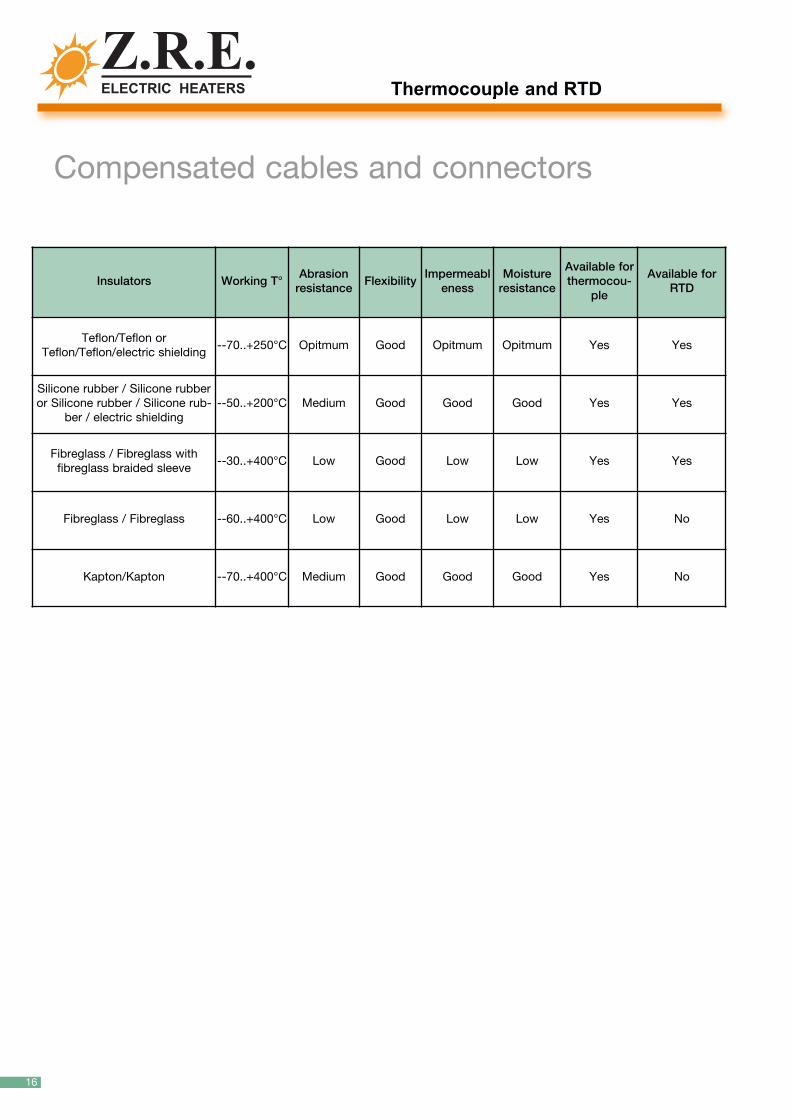
Compensated cables and connectors
Insulators Working T°Abrasionresistance
Flexibility Impermeabl
enessMoistureresistance
Available forthermocou-
ple
Available forRTD
Teflon/Teflon orTeflon/Teflon/electric shielding
--70..+250°C Opitmum Good Opitmum Opitmum Yes Yes
Silicone rubber / Silicone rubberor Silicone rubber / Silicone rub-
ber / electric shielding--50..+200°C Medium Good Good Good Yes Yes
Fibreglass / Fibreglass with fibreglass braided sleeve
--30..+400°C Low Good Low Low Yes Yes
Fibreglass / Fibreglass --60..+400°C Low Good Low Low Yes No
Kapton/Kapton --70..+400°C Medium Good Good Good Yes No
Thermocouple and RTD
16

17
Connectors
Standard male connector suitable for:
Type Code
H 28SK1LB
J 24SJ1LB
S 33SS1LB
T 36ST1LB
12.512.5
25.3
25.3
3030
11.5
11.5
Standard movable female connector suitable for:
Type Code
K 30SK2LB
J 25SJ2LB
S 34SS2LB
T 37ST2LB
12.512.5
25.3
25.3
3838
Standard female connector for panelboard(with template) suitable for
Type Code
K 32SK2LB
J 27SJ4LB
S 35SS4LB
T 39ST4LB
Miniature movable male connector suitable for:
Miniature movable female connector suitable for:
Type Code
K 12MK1LB
J 07MJ1LB
S 17MS1LB
T 21MT1LB
Type Code
K 13MK2LBJ 09MJ2LB
S 18MS2LB
T 22MT2LB
1919
3838
442727
88
16.5
16.5
2020
8.5
8.5
88
16.5
16.5
26.526.5

10040 San Gillio - Torino (Italy) - Via Druento, 48/2Tel. +390119841848 8 linee R.A. - Fax +390119848099e-mail: [email protected] www.zre.it
© Cop
yright Z.R.E. 2
008 - Rev 1.2 - All rig
ht re
served
marking according to standard 2006/95/CE of 11/12/2006