Dry mortar production line——Hengfu Electronic Machinery Co.,LTD

Naturally good – the dry mortar with outstanding thermal conductivity
THERMOCEM®

2
CONTENTS
1. Product description 3
2. Achievability of thermal conductivity levels 3
3. Suspension properties 4 3.1 Marsh time 4
3.2 Water separation 5
4. Advice on working with the product 6 4.1 Adding water 6
4.2 Quality assurance on the building site 7
5. Machinery and equipment 8 5.1 Mixing operation 8
6. Backfilling the borehole 10 6.1 Backfilling operation using an underwater concreting process 10
6.2 Ending the backfilling operation 11
7. Development of strength and hydration heat 12 7.1 Setting process 12
7.2 Development of early strength and end-strength 13
8. Borehole resistance 14
9. Chemical resistance to aggressive groundwater 15 9.1 Classifying the level of the attack 15
9.2 Resistance to sulphate and lime-dissolving carbonic acid 16
10. Frost-thaw resistance 18
11. Magnetic Susceptibility 20

3
1. Product description for ThermoCem® PLUS■■ ThermoCem PLUS comes in a pure powder form.■■ ThermoCem PLUS contains no quartz sand and is non-abrasive in mixers/pumps.■■ ThermoCem PLUS is a premixed product and is ready-to-use after the specified
quantity of water has been added.■■ ThermoCem PLUS contains swellable clay minerals that enable it to swell in situ.■■ ThermoCem PLUS contains a special binder that exhibits particularly high resistance
to concrete-aggressive waters (e.g. sulphates, carbonic acid).■■ ThermoCem PLUS is subject to internal and external quality monitoring, meaning that
consistently high quality is assured.■■ ThermoCem PLUS comprises selected raw materials and is accordingly suitable for
use in groundwater protection areas, having regard to water hygiene.
For projects with a lower requirement on thermal conductivity for the
backfilling material, we offer an ideal alternative in ThermoCem Light,
which has a thermal conductivity of λ ≈ 1.0 W/mK
2. Achievability of thermal conductivity levelsVarious options are available for increasing the
thermal conductivity of a construction material. One
basis for this, for example, could be to add graded
quartz sand, that is to say aggregates. In order to
come close to achieving reliable thermal conductivity
of 2.0, this requires a relatively high share by weight
of the aggregate. It is a completely different story
with our ThermoCem PLUS product. We employ
a selected additive to ensure that we reliably achieve
thermal conductivity (λ) of approx. 2.0 W/mK. The
volume of the product required and the rheology are
then matched to the specific application.
ThermoCem 04λ ≈ 4,0 W/(m*K)
Suspension density
Ther
mal
con
duct
ivity
ConcreteThermoCem PLUSλ ≈ 2,0 W/(m*K)
ThermoCem Basicλ ≈ 0,8 W/(m*K)
W/(m*K)
4
3,75
3,5
3,25
3
2,75
2,5
2,25
2
1,75
1,5
1,25
1
0,75
0,5
0,25
0
1000 1200 1400 1600 1800 2000 2200 kg/m3
THERMOCEM | Naturally good
4
3. Suspension properties
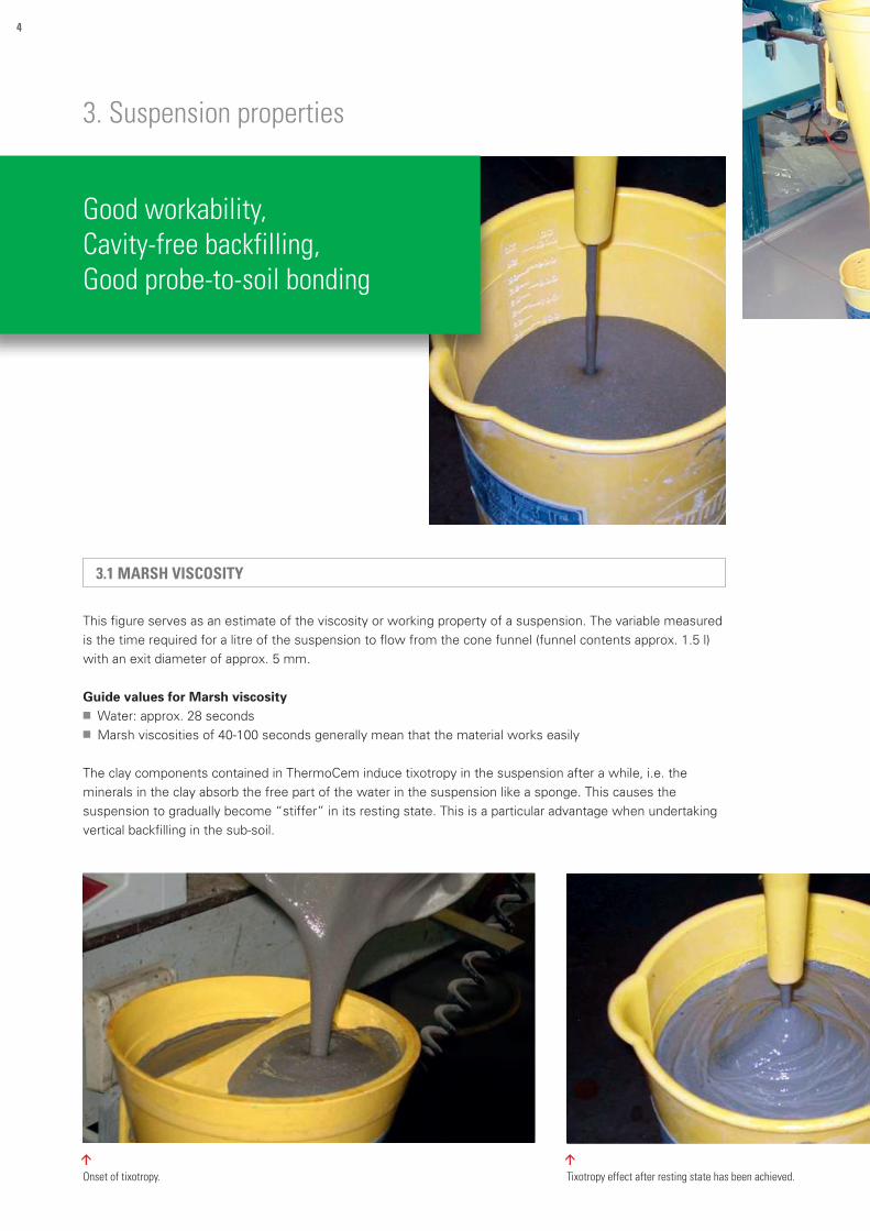
3.1 MARSH VISCOSITY
This figure serves as an estimate of the viscosity or working property of a suspension. The variable measured
is the time required for a litre of the suspension to flow from the cone funnel (funnel contents approx. 1.5 l)
with an exit diameter of approx. 5 mm.
Guide values for Marsh viscosity■■ Water: approx. 28 seconds■■ Marsh viscosities of 40-100 seconds generally mean that the material works easily
The clay components contained in ThermoCem induce tixotropy in the suspension after a while, i.e. the
minerals in the clay absorb the free part of the water in the suspension like a sponge. This causes the
suspension to gradually become “stiffer” in its resting state. This is a particular advantage when undertaking
vertical backfilling in the sub-soil.
Good workability,Cavity-free backfilling,Good probe-to-soil bonding
<
Onset of tixotropy.
<
Tixotropy effect after resting state has been achieved.
5
Keeping to the formulation,Stabilisation using clay minerals,Matching the mixer to the construction material
<Determining the Marsh viscosity after mixing.
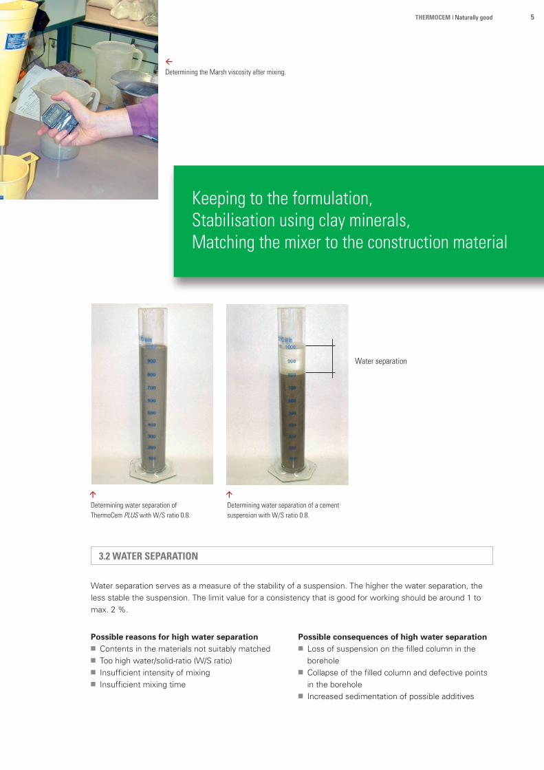
3.2 WATER SEPARATION
Water separation serves as a measure of the stability of a suspension. The higher the water separation, the
less stable the suspension. The limit value for a consistency that is good for working should be around 1 to
max. 2 %.
Possible reasons for high water separation■■ Contents in the materials not suitably matched■■ Too high water/solid-ratio (W/S ratio)■■ Insufficient intensity of mixing■■ Insufficient mixing time
Possible consequences of high water separation■■ Loss of suspension on the filled column in the
borehole■■ Collapse of the filled column and defective points
in the borehole■■ Increased sedimentation of possible additives
<
Determining water separation of ThermoCem PLUS with W/S ratio 0.8.
<
Determining water separation of a cementsuspension with W/S ratio 0.8.
Water separation
THERMOCEM | Naturally good

6
No. of sacks
Quantity of ThermoCem
Volume of water to be added
Suspensionvolume
[Stck.] [kg] [l] [l]
1 25 20 31
2 50 40 62
3 75 60 93
4 100 80 124
5 125 100 155
6 150 120 186
Mixing table for ThermoCem with W/S ratio 0.8.
4. Advice on working with the product
4.1 ADDING WATER
ThermoCem PLUS is a pre-mixed product that only requires water to be added to it on the building site. The technical properties we indicate for ThermoCem PLUS can only be achieved if the material is admixed with the designated quantity of water.
This means that the most important factor during admixing is what is known as the water/solid ratio (W/S
ratio). It is the quotient by mass of the required amount of water and of the construction material. The W/S
ratio is determined by our formulation. If the ThermoCem is being admixed using a batch mixer, please note
the fill volume per batch. The formulation should be laid on to approx. 85 % of the mixer volume. In that way,
it is possible to avoid the suspension from “spilling over”.
Example: working volume of mixer 150 l x 0.85 = 127.5 l
The construction material feed is ideally always geared to whole sacks, as part quantities are relatively difficult
to estimate. For this example, the feed is calculated as follows:
First put in 80 litres of water and then add 4 sacks of ThermoCem. This produces around 124 litres of the suspension.
To fill a 1,000-litre cavity requires the following: 810 kg ThermoCem
and 650 litres water > Suspension density approx. 1,460 kg/m3. Using
the W/S ratio, it is then also possible to calculate the water required per
25 kg sack: 25 kg ThermoCem x 0.8 = 20 litres water. The resulting yield
per 25 kg sack of ThermoCem is approximately 31 litres.

7
4.2 QUALITY ASSURANCE ON THE BUILDING SITE
To check on the correct mixing ratio, the only reliable measure is the suspension density. Regular checking
during the backfilling operation is essential to ensure the quality of the filling. The DVGW study (2003) on
investigations to determine quality criteria in well construction, “Untersuchungen zur Bestimmung von Qualität-
skriterien im Brunnenbau”, has demonstrated that it is also sensible to compare the suspension density in the
mixer with the suspension discharged at the head of the borehole. If both density values agree, it can be
assumed that the cavity has been uniformly filled.
The following procedures for measuring density on-site are commonplace:■■ Determination of density using an areometer■■ Determination of density using a mud balance■■ Determination of density using household scales (5 kg) and a defined litre vessel
4.3 CHANGE IN W/S RATIO
But what happens if the W/S value is changed? The table below is intended to provide a brief overview of the
changes in the technical properties if the specified proportion of water is not observed correctly:
Technical properties Increasing the proportion of water: Reducing the proportion of water:
Viscosity Reduces viscosity Increases viscosity
Water separation Increases water separation Reduces water separation
Thermal conductivity Reduces thermal conductivity Increases thermal conductivity
Strengths Reduces strengths Increases strengths
Resistance to frost-thaw Lower resistance Improved resistance
Water permeability Increases water permeability Reduces water permeability
Quantity of construction material required
Reduces consumption of material Increases consumption of material
<Mud balance
<5 kg Household scales
<Areometer
TARGET ACTUAL
THERMOCEM | Naturally good

8
5.1 MIXING PROCEDURE
The quality of the suspension to be worked is not demonstrated solely in the deliberate choice of the individual components. The stated properties can only be achieved, and even enhanced, using the mixing procedure that is suited to it.Fundamentally, it is possible to distinguish between the following types of mixing:
5. Machinery and equipment
MIXING PROCEDURE
MUD TANKLOW-SPEED HIGH-SPEED
BATCH MIXERFLOW MIXER SOLELY BATCH MIXER

9
Low-speed mixers are mainly designed for the mixed-particle range, where pump-conveyed consistencies are admixed or pumped. Flow mixing (or continuous mixing) systems are often used for geothermal construction sites. Depending on the manufacturer, the quality of the admixed ThermoCem suspension may be adequate. However, if purchasing a new machine it is advisable to test for suitability.
By contrast, colloidal mixers work with very high shearing forces and turbulences. ThermoCem PLUS
suspensions that have been dispersed in this way achieve optimum consistency.
The additional advantage is that colloidal mixers are always batch mixers. This means that the user is always
able to maintain practically identical W/S ratio mix for mix.
In addition, the suspension can be subjected to a sight check. If suspensions have to be set to be more
viscous, due to the geological conditions (fissures, pore chambers), this can be adjusted not only by reducing
the W/S ratio (which means a simultaneous increase in the materials requirement), but in this case also by
adjusting the mixing time in the colloidal mixer.
Viscosity of ThermoCem PLUS as a function of mixing speed(mixing time: 2 min.)
Viscosity of ThermoCem PLUS as a function of mixing time(mixing speed: 1250 rpm)
As a special type of “mixer”, the classic mud tank also merits a mention. Depending on the design of
the tank size and circulating spiral pump, the mixing results achieved range from good to very good.
The advantage lies in the mixing time.
Given the time necessary to prepare a mix in the tank, the ThermoCem PLUS suspension is
thoroughly mixed through. In view of the viscosity and suspension density achieved, it is possible
to backfill geothermal boreholes to a qualitatively high standard using ThermoCem PLUS. Adequate
suspension volumes (e.g. 1000 l), together with a very high pump rate, are advantageous in forcing
out any drilling fluid that may be present.
Mar
sh v
isco
sity
[s]
Mar
sh v
isco
sity
[s]
Mixing speed [rpm] Mixing time [min]
THERMOCEM | Naturally good

10
6. Backfilling the borehole
6.1 BACKFILLING OPERATION USING AN UNDERWATER CONCRETING PROCESS
Essentially, the backfilling of a geothermal borehole should be carried out as an underwater concreting
process. This means that an additional backfilling hose, mounted on the foot of the probe, or a compression
pipe lowered down to the bottom of the borehole, must be employed as the starting-point for backfilling.
The backfilling operation, which now takes place protected by its own suspension, is a precondition for:■■ Controlled expulsion of any drilling fluid that may be present■■ Preventing demixing of the suspension■■ Cavity-free backfilling
<
Illustration to show the underwater concreting process; homogeneous suspension.
<
Illustration to show “falling” through the water = demixing.
If this method of procedure is not
respected, the material will demix.
In other words, the suspension
“falling” through the standing
water in the borehole or the mud
mix necessarily brings about a
thinning effect.
The proportion of water in the
suspension increases, and can
increase to a level where in some
cases the material fails to harden off.
����������������
��������������� ��
�������������
�������
Before the backfilling operation
During the backfilling operation
Backfilling pipe
Geothermal probe
Groundwater
ThermoCem

11
6.2 ENDING THE BACKFILLING OPERATION
During the backfilling process, the mix ratio is to be checked at regular intervals using the suspension density.
The DVGW study (2003) on investigations to determine quality criteria in well construction, “Untersuchungen
zur Bestimmung von Qualitätskriterien im Brunnenbau“, has demonstrated that it is sensible, particularly with
jetting drilling, to compare the suspension density in the mixer with the suspension discharged at the head of
the borehole. If both density values agree, it can be assumed that the drilling fluid has been completely
expelled.
> www.dvgw.de/fileadmin/dvgw/wasser/gewinnung/w1_01_02.pdf
<
Overflow of water/ThermoCem mixture.
<
Overflow of the water expelled from the borehole.
<
Overflow of pure ThermoCem suspension.
THERMOCEM | Naturally good

12
7. Development of strength and hydration heat
Erosion resistance, Response test,Secure bedding of probes
Source: Stark et al. 2001
7.1 SETTING PROCESS
After admixing ThermoCem with water, an easily-worked suspension is obtained.The clay minerals contained in ThermoCem mean that a tixotropy effect occurs once the suspension ceases to move. It is only some time after that when the actual solidification process starts, i.e. crystals form on the surface of the binder particles.
Where these crystals bridge the spaces between the particles, the material suspension
solidifies and then hardens. This hydration is an exothermic reaction, i.e. heat is generated
during the setting process (hydration heat).
Temperature trend in a ThermoCem test sample under adiabatic conditions.
The estimate of the temperature generated
during the setting process for ThermoCem is
made under adiabatic conditions. This measure-
ment covers the case scenario.
Using the laboratory result, given a start temper-
ature of 24° C a maximum temperature increase
of 5° C can be determined. In the borehole, a
temperature rise of this order is not expected,
since the ambient conditions are different – i.e.
the start temperature is generally lower and the
heat that develops can flow out into the sur-
rounding soil.
SUSPENSION PHASE (liquid) > TIXOTROPIC PHASE (gel) > SOLIDIFICATION (solid) > HARDENING (solid)
22
23
25
27
28
13:00 30:00 38:00 47:00 50:00 55:00
24
26
29
Time [h]
ThermoCem PLUS
Tem
pera
ture
[°C]

13
7.2 DEVELOPMENT OF EARLY STRENGTH AND END-STRENGTH
The development of strength in the ThermoCem is decisively dependent on the ambient
temperature. As a general rule, the colder the ambient temperature, the slower the rate at
which strength develops.
Development of early strength in ThermoCem PLUS at 10° C ambient temperature(shear resistance).
Development of compressive strength in ThermoCem PLUS at 20° C ambient temperature.
1
10
02 1
100
3
THERMOCEM | Naturally good
Time [d]
Shea
r stre
ngth
[kPa
]
4 kPa threshold
for puncture resistance
Age [d]
Com
pres
sive
stre
ngth
[N/m
m2 ]

14
8. Borehole resistance
System safety, Thermal transfer, Optimisation
The transport of heat on geothermal probes from the
thermal carrier liquid to the subsoil and vice versa
depends on the geometry of the borehole, the
installation of the probe pipes in the borehole and
the properties of the materials used. To be able
to transfer heat, a sufficient temperature drop is
required as the driving force. For thermal transfer via
heat conduction, the determining factor is thermal
conductivity. The higher the conductivity, the lower
the temperature drop needed.
Accordingly, the overall resistance acting on the system is dependent on the following factors:■■ Thermal conductivity of the backfilling material■■ Probe material■■ Distance to the side of the probes■■ Borehole geometry
This overall resistance is also described as the
borehole resistance Rb. In a purely analytical study,
it relates to a point at any depth. With a Thermal
Response Test, the effective borehole resistance
Rb* can be determined over the entire length of the
borehole.
The borehole resistance determines the necessary
temperature drop to transfer a given output.
Example:■■ Extraction output: 50 W/m■■ Borehole resistance Rb* (thermal conductivity of
backfilling material λ ≈ 0.8 W/mK) = 0.12 K/(W/m)■■ Borehole resistance Rb* (thermal conductivity of
ThermoCem PLUS λ ≈ 2.0 W/mK) = 0.07 K/(W/m)
■■ 50 W/m x 0.12 K/(W/m) = 6 K■■ 50 W/m x 0.07 K/(W/m) = 3,5 K
In the example shown here, the temperature loss
between the thermal carrier medium and the rock
in a borehole backfilled with ThermoCem is around
2.5 K lower than for backfilling with a standard
material. Depending on the particular instance,
whether heating or cooling, improving the borehole
resistance can contribute to a significant improve-
ment in the performance capability of a geothermal
plant.
Source: M. Reuss, ZAE
Backfilling material Rock
Flow
Tem
pera
ture
T
Distance rrPipe
rBorehole
dPipe wall

15
9. Chemical resistance to aggressive groundwater
Reliable separation of different groundwater storeys and adherence-actuated stabilisation of the annular space can only be achieved for the long term if the backfilling material used exhibits adequate chemical resistance to the waters found on site. In the case of ce-ment-bound backfill materials, the strength of a chemical attack can be estimated as a provi-sional measure using DIN EN 206.
This standard indicates contents in the water and
pH values that are to be classified as aggressive to
concrete. Concentration ranges are defined for
each concrete-aggressive content material in
water, corresponding to the exposure categories
XA1 (weak attack), XA2 (moderate attack) or XA3
(strong attack). The highest exposure category
identified when studying each of the individual
aggressive materials determines the overall
classification. If a chemical attack is present, this
needs to be taken into account in the choice of
backfilling material.
We point out that the potential aggressiveness to
construction materials of localised groundwater
must always be examined specific to the individual
project, by means of suitable water analysis. To
assess the potential aggressiveness of the ground-
water, as part of the analysis the following should
be determined as a minimum: pH value, electrical
conductivity, and the concentrations of water
contents to be classified pursuant to DIN EN 206
as aggressive to concrete – sulphate, magnesium,
ammonium and lime-dissolving carbonic acid.
Durability, Resistance, Ground - w ater aggressive to concrete
9.1 CLASSIFYING THE LEVEL OF THE ATTACK
Exposure category
XA1 XA2 XA3
Content in water weakly aggressive moderately aggressive strongly aggressive
SO42- [mg/l] 200-600 > 600-3000 > 3000-6000
NH4+ [mg/l] 15-30 > 30-60 > 60-100
Mg2+ [mg/l] 300-1000 > 1000-3000 > 3000 to saturation
pH value 6.5-5.5 < 5.5-4.5 < 4.5 and 4.0
CO2(aq) [mg/l] 15-40 > 40-100 > 100 to saturation
Concrete-aggressive contents in water; limits for exposure categories pursuant to DIN EN 206. Source: DIN
THERMOCEM | Naturally good

16
To achieve the high chemical resistance of ThermoCem PLUS and ThermoCem Light to waters containing sulphate, these products make exclusive use of a cement with a high sulphate resistance pursuant to DIN 1164. In addition to this, the formulations for these construction materials are designed such that they exhibit significantly increased chemical resistance to acid attacks (e.g. carbonic acid) compared with a standard backfilling material (e.g. Dämmer – Das Original).
The chemical resistance of ThermoCem PLUS and
ThermoCem Light against carbonic acid attack was
investigated in our laboratories in a comprehensive
series of tests. A core part of these investigations
were storage tests whereby water containing
carbonic acid was passed round samples of the
construction materials over a period of 90 days and
the surface softening of the test samples docu-
mented. The measurement of surface softening
was carried out using Vicat needle penetration
depth pursuant to DIN EN 196-3.
The carbonic acid concentration of the storage
water was 100 mg per litre, thereby corresponding
to exposure category XA3 (strong chemical attack).
The permanent flow of water around the test
samples, using fresh water containing carbonic
acid, simulates a “worst-case” scenario.
By comparison with the situation on a real construc-
tion measure, the storage test accordingly provokes
accelerated softening of the construction material,
thereby producing an effect of time compression.
This makes it possible to estimate the influence of
the contaminant over a longer period, despite the
limited duration of the test.
Even under these extreme test conditions,
ThermoCem PLUS and ThermoCem Light exhibit
only slight surface softening.
9.2 RESISTANCE TO SULPHATE AND CARBONIC ACID
9. Chemical resistance to aggressive groundwater

17
Chemical resistance to lime-dissolving carbonic acid. Trend over time for softening of the surface.Carbonic acid concentration of the storage water 100 mg/l (exposure category XA3, strong chemical attack).
Both construction materials satisfy the endurance criterion customary
for sealing wall applications for a needle penetration depth of < 2mm
after 90 days in storage.
By contrast, the surface softening of a standard backfilling material
(Dämmer – Das Original) exceeds this endurance criterion by more
than a factor of three.
Vica
t nee
dle
pene
tratio
n de
pth
[mm
]
Long-term test [days]
Endurance criterion: Vicat needle penetration depth < 2mm
Dämmer – das Original
ThermoCem PLUS
ThermoCem Light
THERMOCEM | Naturally good
18
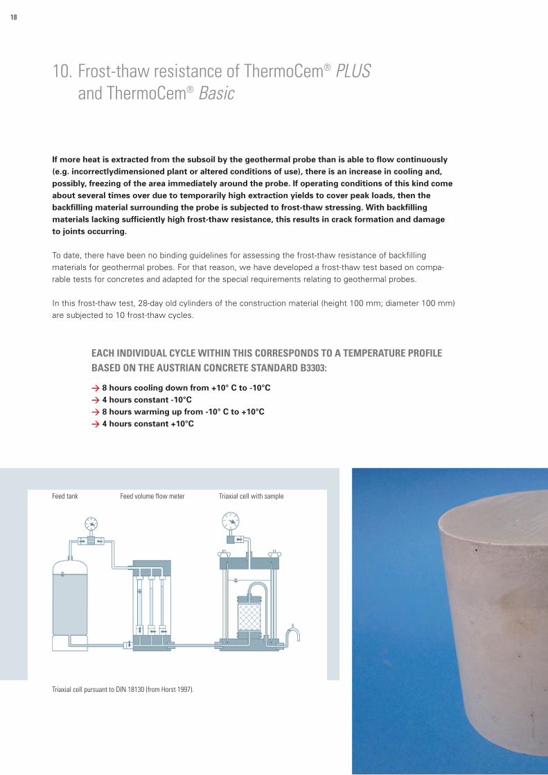
10. Frost-thaw resistance of ThermoCem® PLUS and ThermoCem® Basic
Triaxial cell pursuant to DIN 18130 (from Horst 1997).
If more heat is extracted from the subsoil by the geothermal probe than is able to flow continuously (e.g. incorrectlydimensioned plant or altered conditions of use), there is an increase in cooling and, possibly, freezing of the area immediately around the probe. If operating conditions of this kind come about several times over due to temporarily high extraction yields to cover peak loads, then the backfilling material surrounding the probe is subjected to frost-thaw stressing. With backfilling materials lacking sufficiently high frost-thaw resistance, this results in crack formation and damage to joints occurring.
To date, there have been no binding guidelines for assessing the frost-thaw resistance of backfilling
materials for geothermal probes. For that reason, we have developed a frost-thaw test based on compa-
rable tests for concretes and adapted for the special requirements relating to geothermal probes.
In this frost-thaw test, 28-day old cylinders of the construction material (height 100 mm; diameter 100 mm)
are subjected to 10 frost-thaw cycles.
EACH INDIVIDUAL CYCLE WITHIN THIS CORRESPONDS TO A TEMPERATURE PROFILE BASED ON THE AUSTRIAN CONCRETE STANDARD B3303:
> 8 hours cooling down from +10° C to -10°C> 4 hours constant -10°C> 8 hours warming up from -10° C to +10°C> 4 hours constant +10°C
Feed tank Feed volume flow meter Triaxial cell with sample

19
The test samples are stored in a manner to protect against evaporation.
For this, the base of the test sample is kept permanently in a water-bath.
The water contact simulates groundwater penetration into the area around
the geothermal probe affected by the alternating frost-thaw.
The permeability coefficient (kf value) of the frosted test samples is used
as a test criterion. To that end, the permeability coefficient of the test
sample is determined before and after the frost-thaw test in a triaxial cell
pursuant to DIN 18130 with a hydraulic gradient of i = 30.
A backfilling material can only permanently perform its sealing function if it
exhibits low permeability before and after the frost-thaw test.
<
ThermoCem PLUS after 10 frost-thaw cycles;permanent water storage.
< ThermoCem Basic after 10 frost-thaw cycles;permanent water storage.
In the test series conducted in our laboratory
under the rigorous test conditions described
above, ThermoCem PLUS and ThermoCem Basic
demonstrated a permeability coefficient before
and after the frost-thaw test of ≤ 1·10 -10 m/s.
The frost-thaw stressing did not result in the
emergence of damage to joints, nor in impair-
ment of the sealant effect of the construction
materials.
THERMOCEM | Naturally good

20
11. Geophysical verification of the annular space backfilling
Headline:Verfüllkontrolle mit magnetisch dotiertem ThermoCem PLUS
Bildunterschrift:Beispielhafte Messwertdarstellung
Sond
entie
fe [m
unt
er G
OK]
Magnetsignal [–] Geschwindigkeit [m/Min.]
50
0
-50
-100
-150
-200
-2500 2 4 6 8 10 -2 -1 0 1 2
<
Proof of the annular space backfilling.
SUPERVISION OF THE BACKFILLING PROCESS WITH MAGNETICALLY-DOPED THERMOCEM® PLUS
SENSYS GmbH

21
The more-advanced quality-control directives for the construction of geothermal heat probes require the verification of a complete annular space backfilling.
One possibility is the verification with the aid of geophysical methods. For example,
magnetically- doped backfilling construction materials can be verified unambiguously by the
employment of magnetometer probes. The miniaturization of this measurement technology
makes it possible to drive the tubes of usual soil warming probes, with miniature-design
magnetometers, to the depth required.
ThermoCem PLUS “doped” is a magnetically-doped backfilling construction material. In this
way, the presence or non-presence of the backfilling construction material in the annular space
can be verified unambiguously, using the measurement technology described, by means of the
measurement of the magnetic susceptibility.
As well as the measurement of the rise of the suspension column during the annular space
backfilling, the utilization of ThermoCem PLUS “doped” also enables repeated measurements
at a later time.
< Example of measurement presentation.
< Sensor, Incremental encoder, Data collection. SENSYS GmbH
< Probe. SENSYS GmbH
Headline:Verfüllkontrolle mit magnetisch dotiertem ThermoCem PLUS
Bildunterschrift:Beispielhafte Messwertdarstellung
Sond
entie
fe [m
unt
er G
OK]
Magnetsignal [–] Geschwindigkeit [m/Min.]
50
0
-50
-100
-150
-200
-2500 2 4 6 8 10 -2 -1 0 1 2
Speed [M/min.]Magnetic signal [–]
Dept
h of
the
prob
e [m
bel
ow g
roun
d le
vel]
THERMOCEM | Naturally good

22
23THERMOCEM | Naturally good

WWW.HEIDELBERGCEMENT.DE
0219
/SD3
228U
K/Re
v.2
We would like to stress that achieving the mentioned
properties require a suitable production and processing of
the building material as well as a proper, state-of-the art
preparation on the construction site.
HeidelbergCement AGZur Anneliese 7
D-59320 Ennigerloh
Phone +49 2524 29-51700
Fax +49 2524 29-51715
E-Mail [email protected]
www.heidelbergcement.de/spezialtiefbau