Thermistor Expansion Module Product Manual - Orion Li …€¦ · Thermistor Expansion Module...
15
Thermistor Expansion Module Product Manual (document revision 2.1) Revision A (metal case) Revision B (plastic case) An Ewert Energy Systems, Inc Product The Orion BMS and this expansion module are designed and manufactured by Ewert Energy Systems, Inc which is a research & development company focusing on developing solutions for plug-in hybrid and electric vehicles. Ewert Energy provides custom solutions as well as off the shelf components.
Transcript of Thermistor Expansion Module Product Manual - Orion Li …€¦ · Thermistor Expansion Module...

Thermistor Expansion Module
Product Manual (document revision 2.1)
Revision A (metal case)
Revision B (plastic case)
An Ewert Energy Systems, Inc Product
The Orion BMS and this expansion module are designed and manufactured by
Ewert Energy Systems, Inc which is a research & development company focusing
on developing solutions for plug-in hybrid and electric vehicles. Ewert Energy
provides custom solutions as well as off the shelf components.
Thermistor Expansion Module Manual – Rev 2.1
2
Table of Contents
Product Description and Specifications ............................................................................................ 3
Product Description .................................................................................................................................................................. 3
Product Specifications .............................................................................................................................................................. 3
Installation & Wiring ............................................................................................................................ 4
Connector Overview ................................................................................................................................................................. 4
Thermistor Connector ............................................................................................................................................................... 4
Power Connector...................................................................................................................................................................... 5
Connecting to BMS .............................................................................................................................. 8
CAN Connection....................................................................................................................................................................... 8
Analog Connection ................................................................................................................................................................... 9
Software Configuration ..................................................................................................................... 10
Setting Up The OrionBMS Profile ........................................................................................................................................... 10
Setting Up The Thermal Board Software ................................................................................................................................ 11
Additional Thermistor Utility Features: .................................................................................................................................... 12
Operation ............................................................................................................................................ 13
Troubleshooting ................................................................................................................................. 14
Electrical & Product Specifications .................................................................................................. 15
Thermistor Electrical Specifications: ....................................................................................................................................... 15
Expansion Module Dimensions: ............................................................................................................................................. 15
Connector Part Numbers (Rev. B units only): ......................................................................................................................... 15
Thermistor Expansion Module Manual – Rev 2.1
3
Product Description and Specifications
Product Description The Orion BMS thermistor expansion module provides up to an additional 80 thermistor inputs (beyond
the 4 that are supported by the main unit or two that are supported by the Orion Jr. BMS) for monitoring
temperatures on large battery packs or situations where every cell temperature needs to be monitored.
Up to 10 thermistor expansion modules can be used together with one BMS for a total of 804
thermistors. For the Orion Jr. BMS, one thermistor expansion module can be used to monitor up to 80
thermistors.
Product Specifications ● Operates with the Orion BMS or Orion Jr. BMS from Ewert Energy Systems (BMS sold
separately) or can be used as a standalone temperature monitoring device. ● Full automotive operating and sensing temperature range (-40C to 80C). ● High noise immunity. ● Communicates via CANBUS and can operate on several different CANBUS frequencies (125
Kbps, 250 Kbps, 500 Kbps, 1000 Kbps). ● Highest and lowest thermistor values are transmitted both via CANBUS and analog outputs. ● Can be configured to measure between 1 and 80 thermistors.
Thermistor Expansion Module Manual – Rev 2.1
4
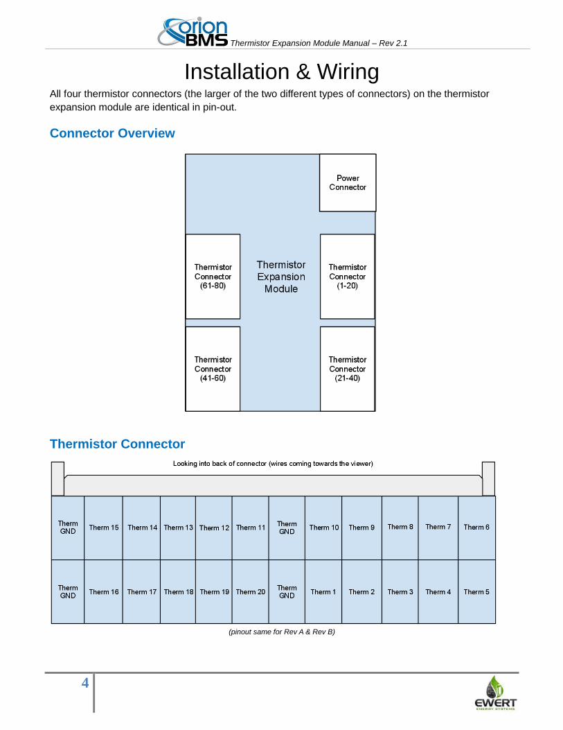
Installation & Wiring All four thermistor connectors (the larger of the two different types of connectors) on the thermistor
expansion module are identical in pin-out.
Connector Overview
Thermistor Connector
(pinout same for Rev A & Rev B)
Thermistor Expansion Module Manual – Rev 2.1
5
Signal Name Description
Therm X (Thermistor Input) This is the input from a given thermistor and should
register 0-5v depending on the temperature.
Therm GND (Thermistor Ground) This is the ground side of a thermistor. In many cases
there are several thermistor grounds tied together to
reduce connector cost and board space.
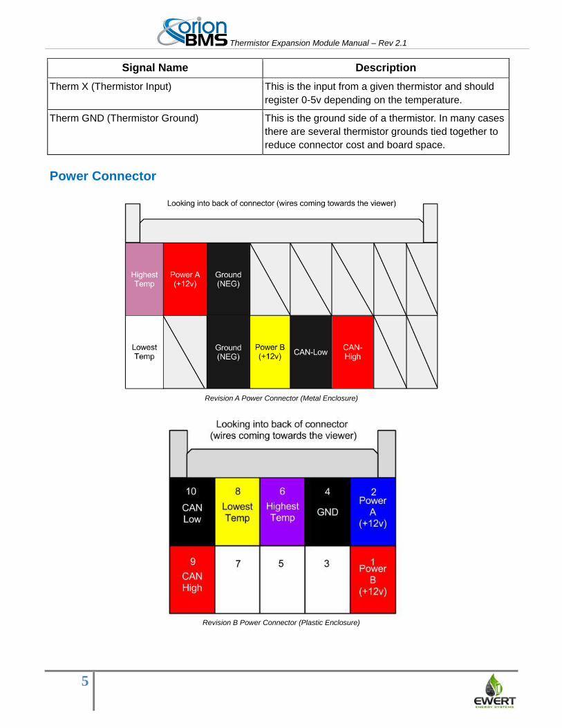
Power Connector
Revision A Power Connector (Metal Enclosure)
Revision B Power Connector (Plastic Enclosure)
Thermistor Expansion Module Manual – Rev 2.1
6
Signal Name Description
Power A (+12v) This is the primary +12v power source for the
expansion module. The module will respond and act
the same regardless of whether the power A or B
signal is used to power it. A common configuration
might be to use the Power A signal to power the
module during normal operation and Power B signal
to power it while charging. Another common
configuration would be to power both A and B signals
for redundancy.
Power B (+12v) This is a secondary +12v power source for the
expansion module. The module will respond and act
the same regardless of whether the power A or B
signal is used to power it. A common configuration
might be to use the Power A signal to power the
module during normal operation and Power B signal
to power it while charging. Another common
configuration would be to power both A and B signals
for redundancy.
Ground (NEG) This is the power ground for the board. It should be
connected to ground.
CAN-H This is the CANBUS high wire used to communicate
with the Orion BMS. This should be shielded and
twisted together with CAN-L. The CANBUS lines
should be bridged with either the CAN1 or CAN2
interface on the Orion BMS.
NOTE: There is NO internal termination resistor
(120 Ohm) between CAN-H and CAN-L. It is the
responsibility of the installer to verify that there are
exactly two (2) termination resistors in the CANBUS
network that the device is being installed in.
CAN-L This is the CANBUS low wire used to communicate
with the Orion BMS. This should be shielded and
twisted together with CAN-H.The CANBUS lines
should be bridged with either the CAN1 or CAN2
interface on the Orion BMS.
NOTE: There is NO internal termination resistor
(120 Ohm) between CAN-H and CAN-L. It is the
responsibility of the installer to verify that there are
exactly two (2) termination resistors in the CANBUS
network that the device is being installed in.
Thermistor Expansion Module Manual – Rev 2.1
7
Highest Temperature This wire provides a voltage representation (0-3.3v
depending on temperature) of the highest measured
thermistor by the module.
This can be directly connected to one of the 4
thermistor inputs on the main Orion BMS module if
CANBUS communication is not possible
(OPTIONAL, but not recommended).
Lowest Temperature This wire provides a voltage representation (0-3.3v
depending on temperature) of the lowest measured
thermistor by the module.
This can be directly connected to one of the 4
thermistor inputs on the main Orion BMS module if
CANBUS communication is not possible
(OPTIONAL, but not recommended).
Thermistor Expansion Module Manual – Rev 2.1
8
Connecting to BMS The following section shows how to connect the thermistor expansion module to the BMS via a CAN connection or via an analog connection. The CAN connection is the preferred connection for the Orion BMS while the analog connection is required for the Orion Jr BMS.
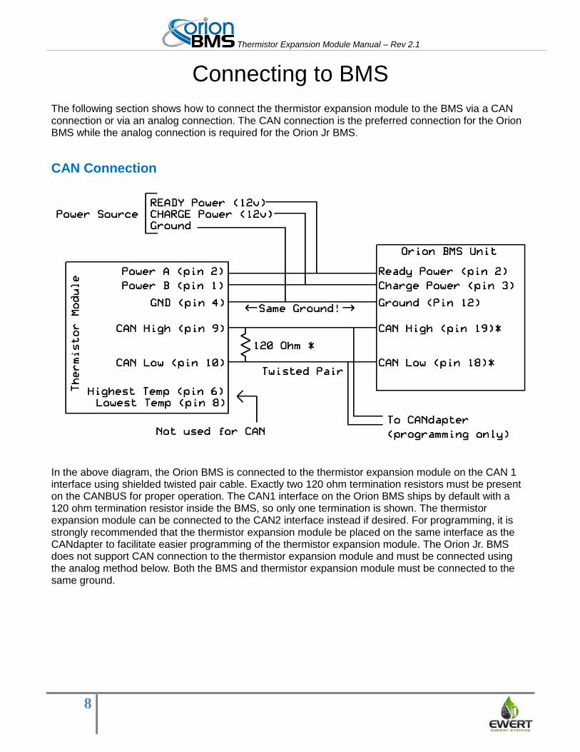
CAN Connection
In the above diagram, the Orion BMS is connected to the thermistor expansion module on the CAN 1 interface using shielded twisted pair cable. Exactly two 120 ohm termination resistors must be present on the CANBUS for proper operation. The CAN1 interface on the Orion BMS ships by default with a 120 ohm termination resistor inside the BMS, so only one termination is shown. The thermistor expansion module can be connected to the CAN2 interface instead if desired. For programming, it is strongly recommended that the thermistor expansion module be placed on the same interface as the CANdapter to facilitate easier programming of the thermistor expansion module. The Orion Jr. BMS does not support CAN connection to the thermistor expansion module and must be connected using the analog method below. Both the BMS and thermistor expansion module must be connected to the same ground.
Thermistor Expansion Module Manual – Rev 2.1
9
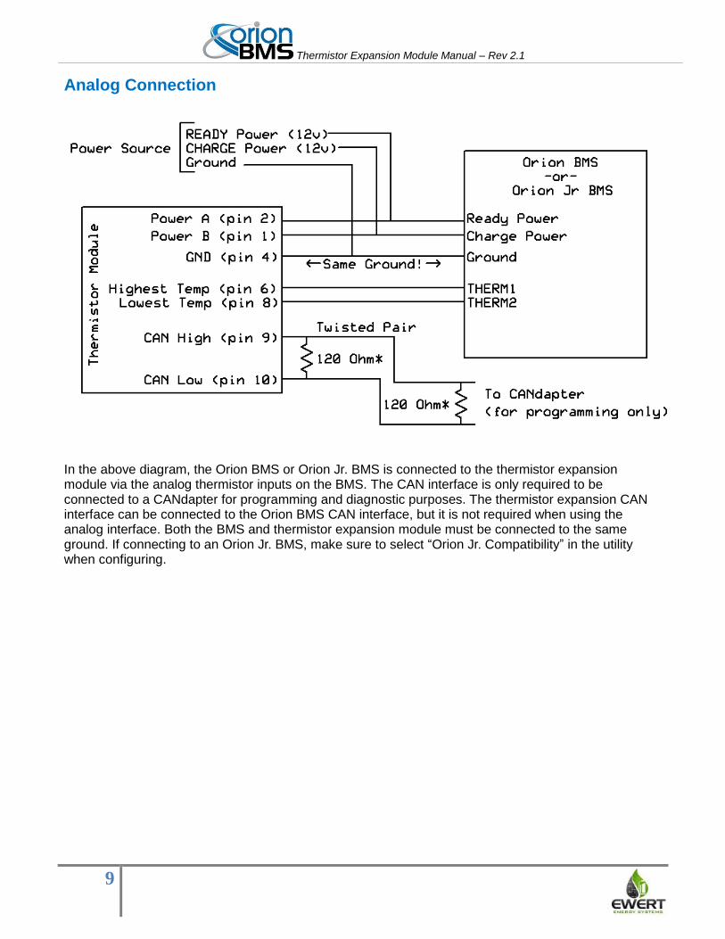
Analog Connection
In the above diagram, the Orion BMS or Orion Jr. BMS is connected to the thermistor expansion module via the analog thermistor inputs on the BMS. The CAN interface is only required to be connected to a CANdapter for programming and diagnostic purposes. The thermistor expansion CAN interface can be connected to the Orion BMS CAN interface, but it is not required when using the analog interface. Both the BMS and thermistor expansion module must be connected to the same ground. If connecting to an Orion Jr. BMS, make sure to select “Orion Jr. Compatibility” in the utility when configuring.
Thermistor Expansion Module Manual – Rev 2.1
10
Software Configuration
There are two areas where the software (configuration) settings regarding the thermistor expansion
module support can be adjusted. The first is the battery profile in the OrionBMS and the second is
settings stored on the actual thermistor expansion module itself (CANBUS baud-rate, CANBUS ID,
number of populated / loaded thermistors, etc).
Setting Up The OrionBMS Profile The following instructions will enable the thermistor expansion module in the OrionBMS battery profile
using the official OrionBMS utility (as shown below in screen shots). These steps assume that the user
has already connected to the BMS and downloaded the most recent battery profile from the BMS (via
the "Receive Current Profile From BMS").
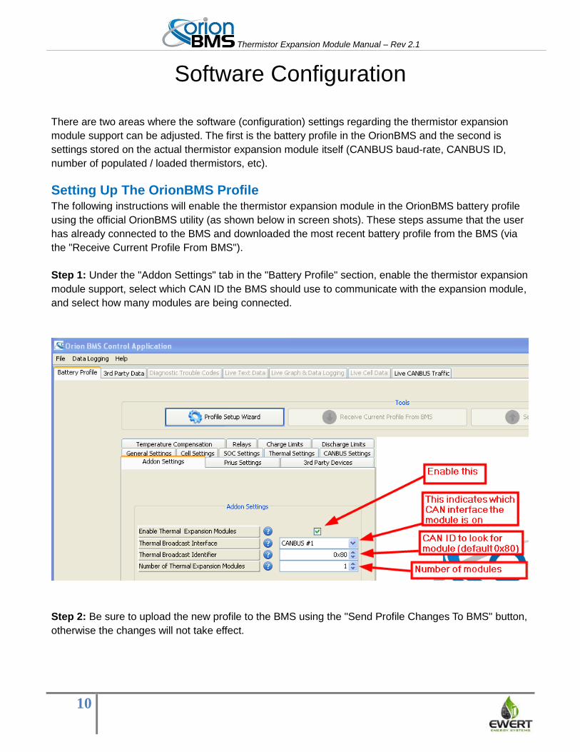
Step 1: Under the "Addon Settings" tab in the "Battery Profile" section, enable the thermistor expansion
module support, select which CAN ID the BMS should use to communicate with the expansion module,
and select how many modules are being connected.
Step 2: Be sure to upload the new profile to the BMS using the "Send Profile Changes To BMS" button,
otherwise the changes will not take effect.
Thermistor Expansion Module Manual – Rev 2.1
11
Setting Up The Thermal Board Software The following instructions assume that the user has installed the OrionBMS thermistor utility (available
from http://www.orionbms.com/support).
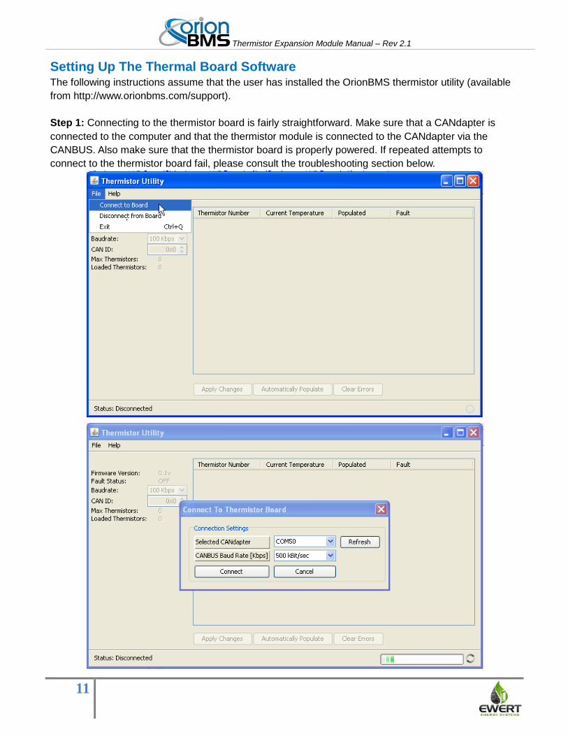
Step 1: Connecting to the thermistor board is fairly straightforward. Make sure that a CANdapter is
connected to the computer and that the thermistor module is connected to the CANdapter via the
CANBUS. Also make sure that the thermistor board is properly powered. If repeated attempts to
connect to the thermistor board fail, please consult the troubleshooting section below.
Thermistor Expansion Module Manual – Rev 2.1
12
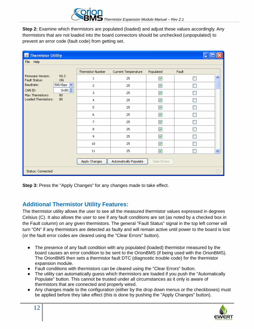
Step 2: Examine which thermistors are populated (loaded) and adjust these values accordingly. Any
thermistors that are not loaded into the board connectors should be unchecked (unpopulated) to
prevent an error code (fault code) from getting set.
Step 3: Press the "Apply Changes" for any changes made to take effect.
Additional Thermistor Utility Features: The thermistor utility allows the user to see all the measured thermistor values expressed in degrees
Celsius (C). It also allows the user to see if any fault conditions are set (as noted by a checked box in
the Fault column) on any given thermistors. The general "Fault Status" signal in the top left corner will
turn "ON" if any thermistors are detected as faulty and will remain active until power to the board is lost
(or the fault error codes are cleared using the "Clear Errors" button).
● The presence of any fault condition with any populated (loaded) thermistor measured by the board causes an error condition to be sent to the OrionBMS (if being used with the OrionBMS). The OrionBMS then sets a thermistor fault DTC (diagnostic trouble code) for the thermistor expansion module.
● Fault conditions with thermistors can be cleared using the "Clear Errors" button. ● The utility can automatically guess which thermistors are loaded if you push the "Automatically
Populate" button. This cannot be trusted under all circumstances as it only is aware of thermistors that are connected and properly wired.
● Any changes made to the configuration (either by the drop down menus or the checkboxes) must be applied before they take effect (this is done by pushing the "Apply Changes" button).
Thermistor Expansion Module Manual – Rev 2.1
13
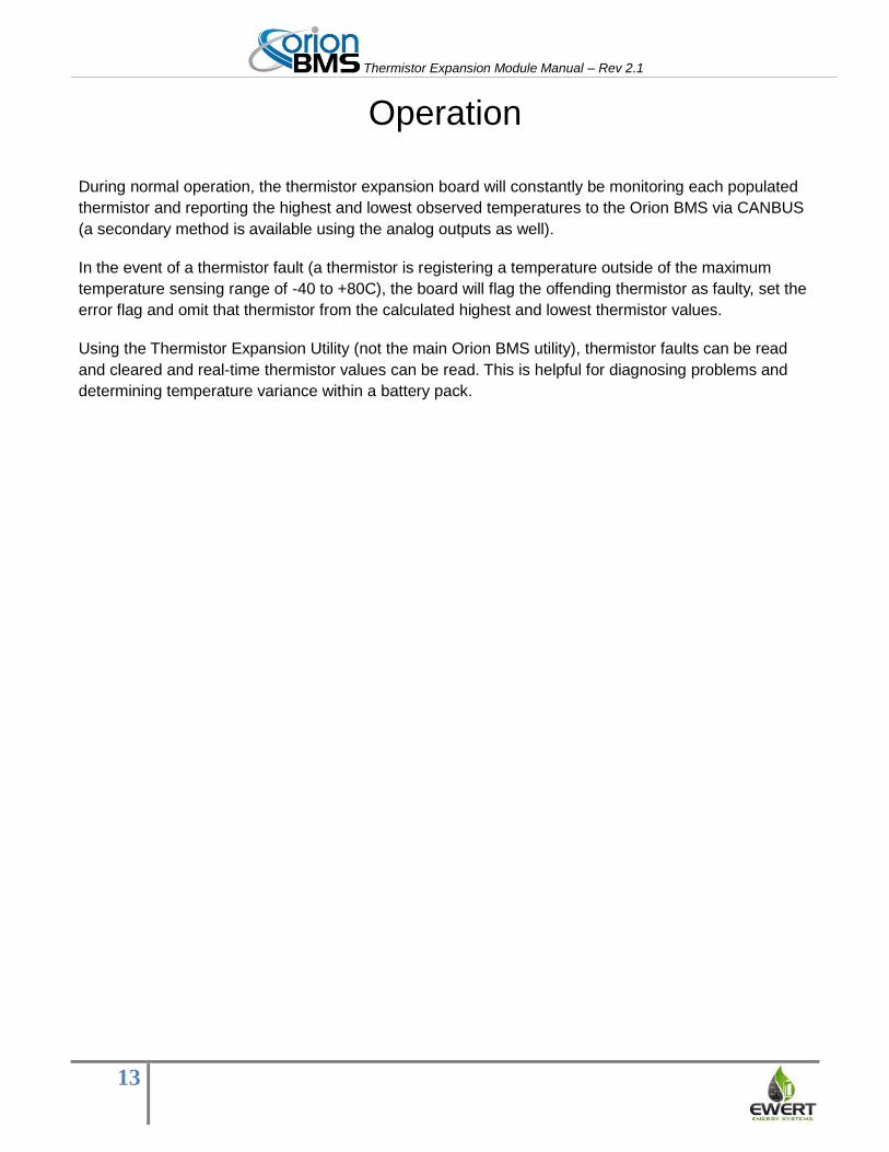
Operation
During normal operation, the thermistor expansion board will constantly be monitoring each populated
thermistor and reporting the highest and lowest observed temperatures to the Orion BMS via CANBUS
(a secondary method is available using the analog outputs as well).
In the event of a thermistor fault (a thermistor is registering a temperature outside of the maximum
temperature sensing range of -40 to +80C), the board will flag the offending thermistor as faulty, set the
error flag and omit that thermistor from the calculated highest and lowest thermistor values.
Using the Thermistor Expansion Utility (not the main Orion BMS utility), thermistor faults can be read
and cleared and real-time thermistor values can be read. This is helpful for diagnosing problems and
determining temperature variance within a battery pack.
Thermistor Expansion Module Manual – Rev 2.1
14
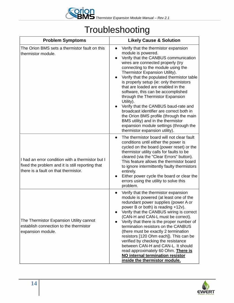
Troubleshooting Problem Symptoms Likely Cause & Solution
The Orion BMS sets a thermistor fault on this
thermistor module.
● Verify that the thermistor expansion module is powered.
● Verify that the CANBUS communication wires are connected properly (try connecting to the module using the Thermistor Expansion Utility).
● Verify that the populated thermistor table is properly setup (ie: only thermistors that are loaded are enabled in the software, this can be accomplished through the Thermistor Expansion Utility).
● Verify that the CANBUS baud-rate and broadcast identifier are correct both in the Orion BMS profile (through the main BMS utility) and in the thermistor expansion module settings (through the thermistor expansion utility).
I had an error condition with a thermistor but I
fixed the problem and it is still reporting that
there is a fault on that thermistor.
● The thermistor board will not clear fault conditions until either the power is cycled on the board (power reset) or the thermistor utility calls for faults to be cleared (via the "Clear Errors" button). This feature allows the thermistor board to ignore intermittently faulty thermistors entirely.
● Either power cycle the board or clear the errors using the utility to solve this problem.
The Thermistor Expansion Utility cannot
establish connection to the thermistor
expansion module.
● Verify that the thermistor expansion module is powered (at least one of the redundant power supplies (power A or power B or both) is reading +12v).
● Verify that the CANBUS wiring is correct (CAN-H and CAN-L must be correct).
● Verify that there is the proper number of termination resistors on the CANBUS (there must be exactly 2 termination resistors [120 Ohm each]). This can be verified by checking the resistance between CAN-H and CAN-L. It should read approximately 60 Ohm. There is NO internal termination resistor inside the thermistor module.
Thermistor Expansion Module Manual – Rev 2.1
15
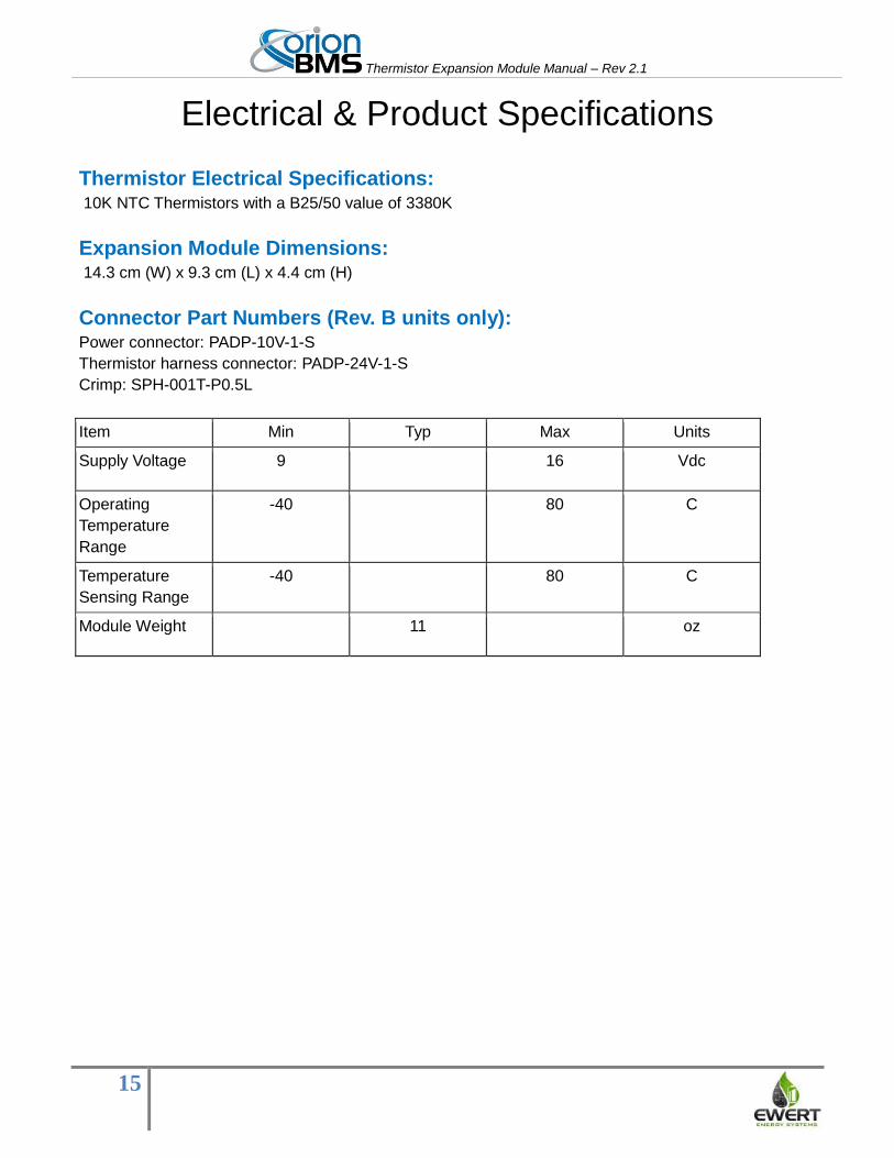
Electrical & Product Specifications
Thermistor Electrical Specifications: 10K NTC Thermistors with a B25/50 value of 3380K
Expansion Module Dimensions: 14.3 cm (W) x 9.3 cm (L) x 4.4 cm (H)
Connector Part Numbers (Rev. B units only): Power connector: PADP-10V-1-S
Thermistor harness connector: PADP-24V-1-S
Crimp: SPH-001T-P0.5L
Item Min Typ Max Units
Supply Voltage 9 16 Vdc
Operating
Temperature
Range
-40 80 C
Temperature
Sensing Range
-40 80 C
Module Weight 11 oz