Thermistor calibration living with the lab © 2013 David Hall.
12
thermistor calibration living with the lab 2013 David Hall
-
Upload
derick-ball -
Category
Documents
-
view
214 -
download
0
Transcript of Thermistor calibration living with the lab © 2013 David Hall.
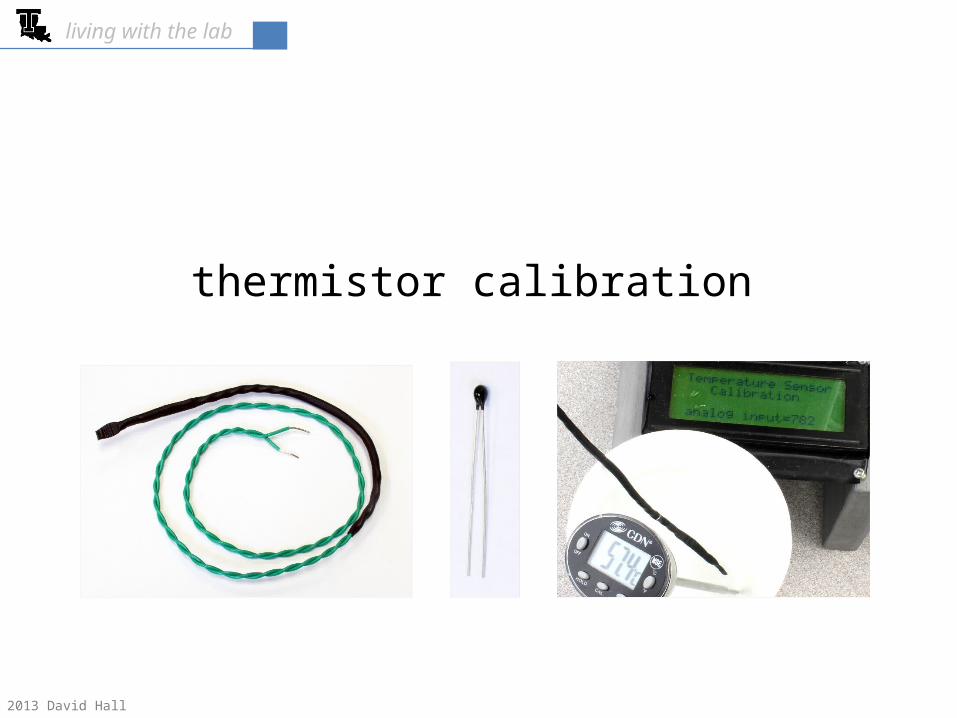
thermistor calibration
living with the lab
© 2013 David Hall

living with the lab
2
The content of this presentation is for informational purposes only and is intended only for students attending Louisiana Tech University.
The author of this information does not make any claims as to the validity or accuracy of the information or methods presented.
Any procedures demonstrated here are potentially dangerous and could result in injury or damage.
Louisiana Tech University and the State of Louisiana, their officers, employees, agents or volunteers, are not liable or responsible for any injuries, illness, damage or losses which may result from your using the materials or ideas, or from your performing the experiments or procedures depicted in this presentation.
If you do not agree, then do not view this content.
The copyright label, the Louisiana Tech logo, and the “living with the lab” identifier should not be removed from this presentation.
You may modify this work for your own purposes as long as attribution is clearly provided.
DISCLAIMER & USAGE

living with the lab
3
• setup includes a laptop, fishtank system, thermistor circuit, thermometer, and cup• the cup is filled with cool water, tap water, and warm water to produce three
calibration points
experimental setup
digital thermometer
thermometer and thermistorare submerged in cup

living with the lab
4
circuit
10kΩ
5V
analog pin 4(measures voltage across 20Ω resistor)
response of Cantherm MF52 series thermistordigikey part #: 317-1258-ND
(resistance = 10kΩ at 25˚C)
0 5 10 15 20 25 30 35 400
5
10
15
20
25
30
temperature (˚C)
resis
tanc
e of
ther
mist
or (k
Ω)
variation of 0 to 1023 analog value with temperature• as temperature increases, the electrical resistance of the thermistor decreases• this causes a decrease in voltage across the thermistor• this causes an increase in voltage across the 10kΩ resistor• this causes the 0 to 1023 output of the analog pin to increase with increasing temperature

living with the lab
5
calibration sketchvoid setup() Serial.begin(9600); // use a baud rate of 9600 bps pinMode(1,OUTPUT); // set pin1 as an output (pin1=TX) Serial.write(12); // clear screen & move to top left position Serial.write(129); // move cursor to row 0, position 1 Serial.write("Temperature Sensor"); // print a text string starting at (0,1) Serial.write(152); // move cursor to row 1, position 4 Serial.write("Calibration"); // print a text string starting at (1,4) Serial.write(189); // move cursor to row 3, position 1 Serial.write("analog input="); // print text string at (3,1) Serial.write(22); // turn cursor off to keep screen clean
void loop()
int analogT; // declare analogT as an integer analogT=analogRead(4); // read the voltage at analog pin 4
Serial.write(202); // move cursor to row 3, position 14 Serial.print(analogT); // print the analog input reading (0 to 1023) Serial.write(" "); // overwrite previously printed numbers

living with the lab
6
CAUTION: Be careful with hot water!
fill the cup about 2/3 full of water at three different temperatures
calibration method
cool water(water fountain is a good source)
tap water warm water(mix hot water with tap water, around 50°C is good)
living with the lab
7
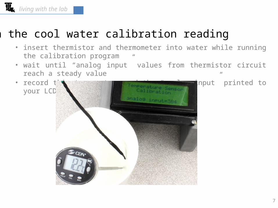
• insert thermistor and thermometer into water while running the calibration program• wait until “analog input” values from thermistor circuit reach a steady value• record this temperature and the “analog input” printed to your LCD
obtain the cool water calibration reading
living with the lab
8
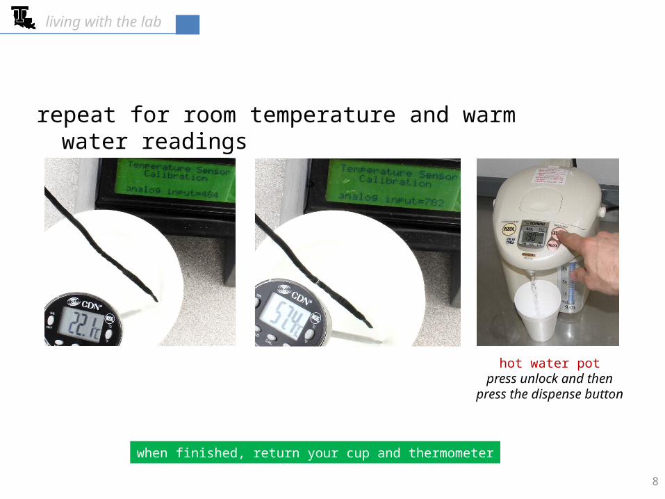
repeat for room temperature and warm water readings
hot water potpress unlock and then
press the dispense button
when finished, return your cup and thermometer

living with the lab
9
use Excel to determine your calibration equation • example values are shown in the table below• use the temperatures and “analog input” values that you collected earlier
temperature analog inputoC (0 to 1023)
12.2 38422.1 48457.4 782
283.79calibration equation
10 15 20 25 30 35 40 45 50 55 600
100
200
300
400
500
600
700
800
900
f(x) = 8.70911742650142 x + 283.791310663273
temperature (˚C)
outp
ut o
f ana
logR
ead
use five digits for these fitting constants

living with the lab
• allow system to reach steady state for room temperature sample• collect 20 “analog input” readings taking a reading every 5 seconds• enter these readings into Excel and compute the standard deviation, σ.• when you write your temperature control sketch, you will set your UCL as the
setpoint plus 3σ and your LCL as the setpoint minus 3σ• for the example below, 3 is equal to 5; if your 3σ is less than one, then set 3σ=1
time
anal
og in
put 520
510
500
490
heat=off heat=off heat=off
heat=on heat=on heat=on
setpoint = 505LCL=setpoint-3 = 500
UCL=setpoint+3 = 510
determine the random error in analog input
10

living with the lab
11
using the calibration equation
calibration equation
if the setpoint is 27oC and 3=5, then the temperature control values are . . .
283.79
The arrows indicate the order that the control parameters are computed.
using algebra, manually invert the calibration equation so you can compute temperatures based on the analog input values returned by the Arduino
quantity T (°C) analogT
UCL 27.6 524
setpoint 27.0 519
LCL 26.4 514
control strategy• if analogT > UCL (or 524) then heater must be off• If analogT < LCL (or 514), then heater must be on
𝑇=0.11482 ∙𝑎𝑛𝑎𝑙𝑜𝑔𝑇−32.585inverted equation

living with the lab
12
CAUTION!Your heater can easily get hot enough to burn you and cause a
fire. NEVER leave your system plugged into a wall outlet when you are not actively testing its performance. You should always be present when the system is plugged into a wall outlet.
Only test your fishtank in an area with a fire extinguisher and an active smoke alarm nearby.