Thermals Fluids 1 Ch 10 Guide
58
10-1 Air at 23 ºC, 100 kPa with a free-stream velocity of 100 km/hr flows along a flat plate. How long does the plate have to be to obtain a boundary layer thickness of 8 mm? Approach: For the distance x from the leading edge to where the boundary layer thickness equals 8 mm, if we assume a turbulent flow, we can use Eq. 10-8 to calculate the distance. We must check the turbulent flow assumption. Assumptions: 1. The boundary layer is turbulent from the leading edge. Solution: Assuming a turbulent boundary layer from the leading edge, the boundary layer thickness can be calculated with Eq. 10-8: ( ) 15 15 0.37 0.37 Re x x x δ ρ µ ∞ = = V Solving for the distance x: ( ) 0.25 5 5 0.37 x δρ µ ∞ ⎡ ⎤ =⎢ ⎥ ⎢ ⎥ ⎣ ⎦ V From Appendix A-7 the air properties at 23ºC are: ρ = 1.177 kg/m 3 and 5 2 1.817 10 Ns m µ − = × . ( ) ( ) ( ) ( ) ( ) ( ) ( ) 0.25 5 3 5 -5 2 2 0.008m 1.177 kg m 100000 m hr 1hr 3600s =0.304m 0.37 1.817×10 Ns m kgm Ns x ⎡ ⎤ ⎢ ⎥ = ⎢ ⎥ ⎣ ⎦ Answer Now we check the Reynolds number: ( ) ( ) ( ) ( ) 3 -5 2 1.177 kg m 100,000 m hr 1hr 3600s 0.304m 547, 000 1.817×10 Ns m x x Re ρ µ = = = V This is turbulent flow as assumed (if turbulence begins at 500,000). 10- 1
description
Introduction to Thermals and Fluids Engineering Chapter 10 Solutions
Transcript of Thermals Fluids 1 Ch 10 Guide
10-1 Air at 23 ºC, 100 kPa with a free-stream velocity of 100 km/hr flows along a flat plate. How long does the plate have to be to obtain a boundary layer thickness of 8 mm?
Approach:
For the distance x from the leading edge to where the boundary layer thickness equals 8 mm, if we assume a turbulent flow, we can use Eq. 10-8 to calculate the distance. We must check the turbulent flow assumption.
Assumptions:
1. The boundary layer is turbulent from the leading edge.
Solution:
Assuming a turbulent boundary layer from the leading edge, the boundary layer thickness can be calculated with Eq. 10-8:
( )1 5 1 5
0.37 0.37Rexx x
δρ µ∞
= =V
Solving for the distance x:
( )
0.255
50.37x δ ρ
µ∞
⎡ ⎤= ⎢ ⎥⎢ ⎥⎣ ⎦
V
From Appendix A-7 the air properties at 23ºC are: ρ = 1.177 kg/m3 and 5 21.817 10 Ns mµ −= × .
( ) ( )( )( )
( ) ( )( )
0.255 3
5 -5 2 2
0.008m 1.177 kg m 100000m hr 1hr 3600s=0.304m
0.37 1.817×10 Ns m kgm Nsx
⎡ ⎤⎢ ⎥=⎢ ⎥⎣ ⎦
Answer
Now we check the Reynolds number:
( )( )( )( )3
-5 2
1.177 kg m 100,000 m hr 1hr 3600s 0.304m547,000
1.817×10 Ns mxx
Reρµ
= = =V
This is turbulent flow as assumed (if turbulence begins at 500,000).
10- 1
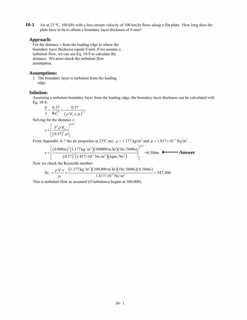
10-2 A large cruise ship has a length, L = 250 m, beam (width), W = 65 m, and draft (depth), D = 20 m. It cruises at 25 km/hr. Assume the flow over the hull can be approximated as that over a flat plate. Estimate:
a. the total skin friction drag (in N) and the power (in kW) to propel the ship on a voyage in the Caribbean where the water temperature is 28 ºC
b. the total skin friction drag (in N) and the power (in kW) to propel the ship on a voyage to Alaska where the water temperature is 4 ºC
Approach:
Assuming we can treat the sides and bottom as flow over a flat plate, and ignoring the form drag at the front, the skin friction can be calculated with the basic drag equation and the appropriate drag coefficient. Power is force times velocity.
Assumptions:
1. The sides and bottom can be treated as flat plates. 2. Seawater properties can be approximated with pure water properties.
Solution:
a) The friction drag force is defined by Eq. 10-6: 2 2D DF C Aρ ∞= V
where A is the planform area: ( ) ( ) 22 250m 65m+2 20m =26,250mA LW LD= + = ⎡ ⎤⎣ ⎦ We need the Reynolds number to evaluate the drag coefficient. We assume we can treat this area as flow over a flat plate. Assuming seawater properties can be approximated by those of pure water from Appendix A-6 at 28 ºC, ρ = 996.1 kg/m3 and µ = 8.16×10⁻⁴ Ns/m2. The length Reynolds number is:
( )( )( )3
9-4 2
996.1kg m 9.62 m s 250m2.936×10
8.16×10 Ns mLL
Reρµ∞= = =
V
This is turbulent flow, so ignoring the laminar contribution and using Eq. 10-8 (even though the Reynolds number is larger than the applicable range):
( ) ( )2.58 2.589
0.455 0.455 0.00138log log 2.936 10
D
L
CRe
= = =⎡ ⎤ ⎡ ⎤×⎣ ⎦ ⎣ ⎦
( )( )( ) ( )( )23 2 20.00138 996.1kg m 9.62m s 26250m Ns kgm 2=1.670×10 NDF = 6 Power is obtained from: ( )( ) ( )61.670×10 N 9.62m s 1kW 1000J s =16,060kWDW F ∞= =V Answer b) The only difference in part (b) is the temperature at which properties are evaluated. At 4 ºC, ρ = 1000 kg/m3 and µ = 15.5×10⁻⁴ Ns/m2.
( )( )( )3
9-4 2
1000 kg m 9.62m s 250m1.552×10
15.5×10 Ns mLL
Reρµ∞= = =
V
( ) ( )2.58 2.589
0.455 0.455 0.00149log log 1.552 10
D
L
CRe
= = =⎡ ⎤ ⎡ ⎤×⎣ ⎦ ⎣ ⎦
( )( )( ) ( )( )23 2 20.00149 1000kg m 9.62m s 26250m Ns kgm 2=1.809×10 NDF = 6
( )( )( )61.809×10 N 9.62m s 1kW 1000J s =17,410kWDW F ∞= =V Answer
Comments: Just by changing the water temperature, the power increase was 8.4%. This is almost entirely due to the change in the water viscosity.
10- 2
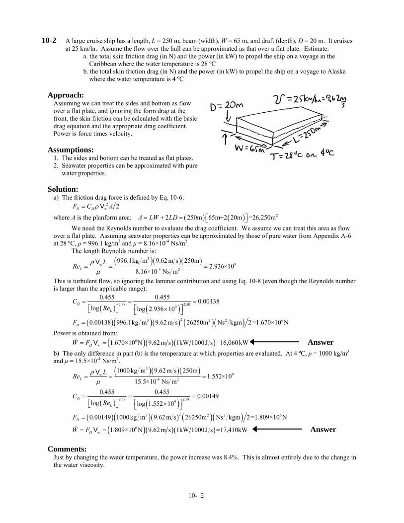
10-3 A 5-mm × 1.5-m × 4-m plastic panel (SG = 1.75) is lowered from a ship to a construction site on a lake floor at a rate of 1.5 m/s. Determine the tension in the cable lowering the panel:
a. assuming the panel descends vertically with its wide end down (in N) b. assuming the panel descends vertically with its narrow end down (in N)
Approach:
This problem requires a force balance on the plastic panel. The buoyancy, drag, tension, and weight forces must be evaluated. We will assume that we can treat the flow as if it is over a flat plate.
Assumptions:
1. The plastic panel is treated as a flat plate. 2. The properties can be approximated with pure water properties.
Solution:
a) A force balance on the plate is: 0 D buoy D buoyF T F F W T W F F= = + + − → = − −∑For the weight: ( )( )( )( )( )( )3 21000kg m 1.75 0.005m 4m 1.5m 9.81m s =515Nplate water plateW Vg SG Vgρ ρ= = = Buoyancy force is: ( )( )( )( )( )3 21000 kg m 0.005m 4m 1.5m 9.81m s =294Nbuoy waterF Vgρ= = The drag force is defined by Eq. 10-6. Accounting for drag on both sides: 22 2D DF C Aρ= V where A is the planform area: ( )( ) 21.5m 4m =6.0mA LH= = We need the Reynolds number to evaluate the drag coefficient. We assume we can treat this area as flow over a flat plate. Assuming properties can be approximated by those of pure water from Appendix A-6 at 10 ºC: ρ = 999.6 kg/m3 and µ = 12.9×10⁻⁴ Ns/m2. The length Reynolds number is:
( )( )( )3
6-4 2
999.6kg m 1.5m s 1.5m1.744×10
12.9×10 Ns mLL
Reρµ
= = =V
This is turbulent flow, but taking into account the laminar contribution at the leading edge:
( )1 5 1 5 66
0.074 1740 0.074 1740 0.003181.744 101.744 10
DLL
CReRe
= − = − =××
( )( )( ) ( )( )23 2 22 0.00318 999.6kg m 1.5m s 6m Ns kgm 2 =42.9 NDF =
Therefore, 515N-42.9N-294 N=178 NT = Answer b) For the narrow end down, the only change is in the drag force:
( )( )( )3
6-4 2
999.6kg m 1.5m s 4m4.649×10
12.9×10 Ns mLL
Reρµ
= = =V
( )1 5 1 5 66
0.074 1740 0.074 1740 0.003064.649×104.649×10
DLL
CReRe
= − = − =
( )( )( ) ( )( )23 2 22 0.00306 99.6kg m 1.5m s 6m Ns kgm 2 =41.3NDF =
515N-41.3N-294.3N=179.7NT = Answer
Comments: Drag plays a minor role in this problem compared to weight and buoyancy.
10- 3

10-4 Your car has broken down on an Interstate highway, and you are on the medium strip between the lanes. By the time you decide you need to cross to the other side of the empty road, a stream of cars moving bumper to bumper at 120 km/hr passes only 1 m away from you. For an air temperature of 25 ºC, determine the velocity (in km/hr) of the wind that will hit you 10 seconds after the first car has passed.
Approach:
Assuming the bumper-to-bumper traffic acts as a flat plate moving through air at 120 km/hr, a boundary layer forms. We can calculate the distance the first car travels in 10 s. We can check the Reynolds number to determine if the flow is laminar or turbulent, and using the appropriate equation, we can calculate the boundary layer thickness. Finally, using an expression for the velocity profile, we can then determine the velocity.
Assumptions:
1. The traffic acts as a flat plate moving through still air. 2. Pressure is one atmosphere.
Solution:
The distance, x, the first car travels is: ( )( )( )120,000m hr 1hr 3600s 10s =333mx t= =V
For air from Appendix A-7 at 25 ºC , 5 21.832 10 Ns mµ −= × and 31.181kg mρ =
( )( )( )( )3
5 2
1.181kg m 120,000m hr 1hr 3600s 333m=715,500
1.832 10 Ns mDRe ρµ −= =
×V
This is turbulent flow. Assuming turbulence begins at the start of the first car, by 10 s later the boundary layer thickness is:
( )( )( )1 5 1 5
333m 0.370.37 =2.09m715,500xx Re
δ δ= → =
Assuming a 1/7th power law velocity profile:
1 7 1 7km 1m km120 =108
hr 2.09m hrx
xyδ∞
⎛ ⎞ ⎛ ⎞⎛ ⎞= → =⎜ ⎟ ⎜ ⎟⎜ ⎟⎝ ⎠ ⎝ ⎠⎝ ⎠
V VV
Answer
Comments: The main assumption (traffic acts as flat plate) is somewhat weak, because the cars act as blunt bodies and the flow around them are different than over a flat plate. Nevertheless, we needed an answer (however approximate), so we needed to make assumptions that would let us determine an answer.
10- 4
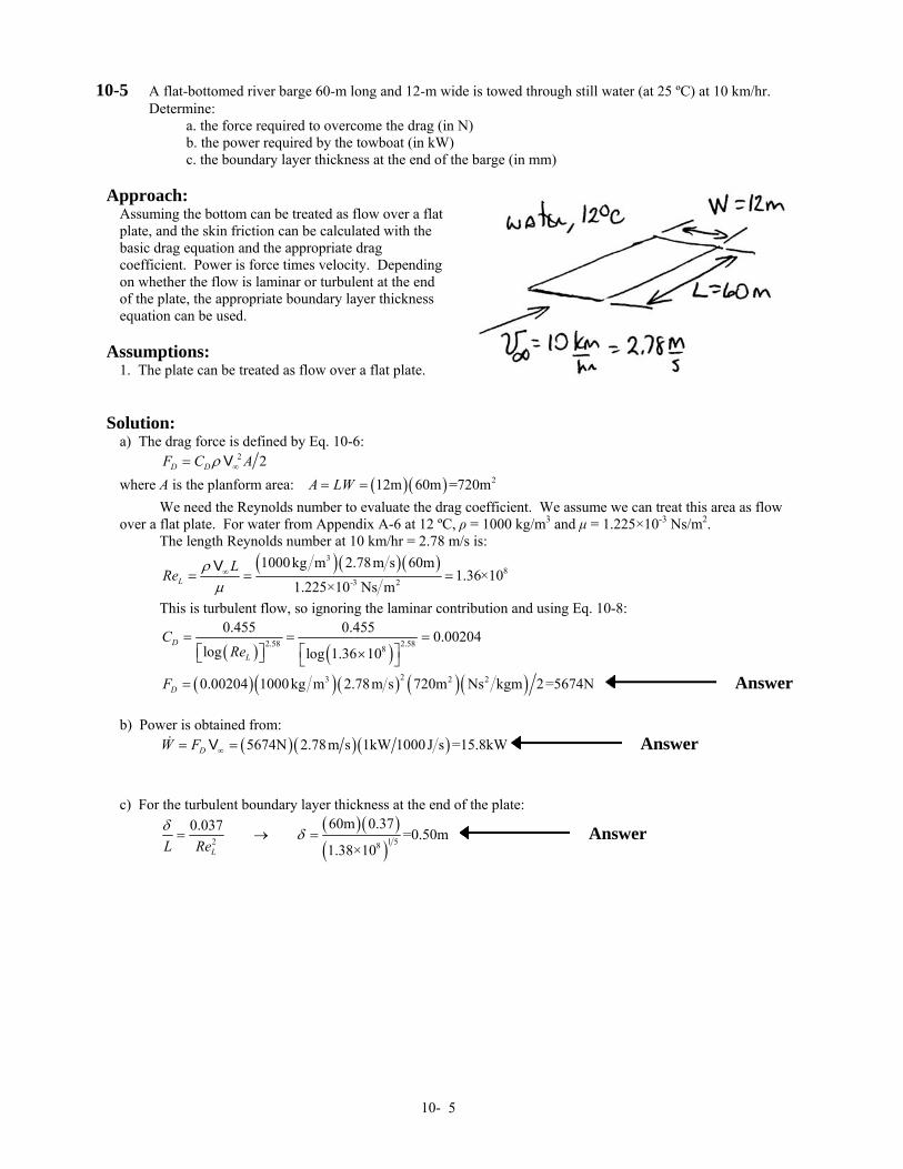
10-5 A flat-bottomed river barge 60-m long and 12-m wide is towed through still water (at 25 ºC) at 10 km/hr. Determine:
a. the force required to overcome the drag (in N) b. the power required by the towboat (in kW) c. the boundary layer thickness at the end of the barge (in mm)
Approach:
Assuming the bottom can be treated as flow over a flat plate, and the skin friction can be calculated with the basic drag equation and the appropriate drag coefficient. Power is force times velocity. Depending on whether the flow is laminar or turbulent at the end of the plate, the appropriate boundary layer thickness equation can be used.
Assumptions:
1. The plate can be treated as flow over a flat plate.
Solution:
a) The drag force is defined by Eq. 10-6: 2 2D DF C Aρ ∞= V where A is the planform area: ( )( ) 212m 60m =720mA LW= = We need the Reynolds number to evaluate the drag coefficient. We assume we can treat this area as flow over a flat plate. For water from Appendix A-6 at 12 ºC, ρ = 1000 kg/m3 and µ = 1.225×10⁻³ Ns/m2. The length Reynolds number at 10 km/hr = 2.78 m/s is:
( )( )( )3
8-3 2
1000kg m 2.78m s 60m1.36×10
1.225×10 Ns mLLRe ρ
µ∞= = =
V
This is turbulent flow, so ignoring the laminar contribution and using Eq. 10-8:
( ) ( )2.58 2.588
0.455 0.455 0.00204log log 1.36 10
D
L
CRe
= = =⎡ ⎤ ⎡ ⎤×⎣ ⎦ ⎣ ⎦
( )( )( ) ( )( )23 2 20.00204 1000kg m 2.78m s 720m Ns kgm 2=5674NDF = Answer b) Power is obtained from: ( )( )( )5674N 2.78m s 1kW 1000J s =15.8kWDW F ∞= =V Answer c) For the turbulent boundary layer thickness at the end of the plate:
( )( )( )2 1 58
60m 0.370.037 =0.50m1.38×10LL Re
δ δ= → = Answer
10- 5
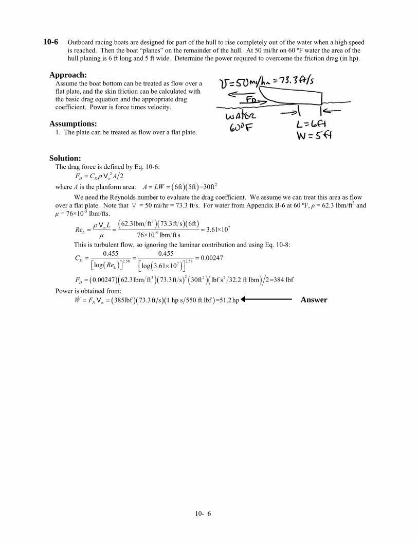
10-6 Outboard racing boats are designed for part of the hull to rise completely out of the water when a high speed is reached. Then the boat “planes” on the remainder of the hull. At 50 mi/hr on 60 ºF water the area of the hull planing is 6 ft long and 5 ft wide. Determine the power required to overcome the friction drag (in hp).
Approach:
Assume the boat bottom can be treated as flow over a flat plate, and the skin friction can be calculated with the basic drag equation and the appropriate drag coefficient. Power is force times velocity.
Assumptions:
1. The plate can be treated as flow over a flat plate.
Solution:
The drag force is defined by Eq. 10-6: 2 2D DF C Aρ ∞= V where A is the planform area: ( )( ) 26ft 5ft =30ftA LW= = We need the Reynolds number to evaluate the drag coefficient. We assume we can treat this area as flow over a flat plate. Note that V = 50 mi/hr = 73.3 ft/s. For water from Appendix B-6 at 60 ºF, ρ = 62.3 lbm/ft3 and µ = 76×10-5 lbm/fts.
( )( )( )3
7-5
62.3lbm ft 73.3ft s 6ft3.61×10
76×10 lbm ft sLL
Reρµ∞= = =
V
This is turbulent flow, so ignoring the laminar contribution and using Eq. 10-8:
( ) ( )2.58 2.587
0.455 0.455 0.00247log log 3.61 10
D
L
CRe
= = =⎡ ⎤ ⎡ ⎤×⎣ ⎦ ⎣ ⎦
( )( )( ) ( )( )23 2 20.00247 62.3lbm ft 73.3ft s 30ft lbf s 32.2 ft lbm 2=384 lbfDF = Power is obtained from: ( )( ) ( )385lbf 73.3ft s 1 hp s 550 ft lbf =51.2hpDW F ∞= =V Answer
10- 6
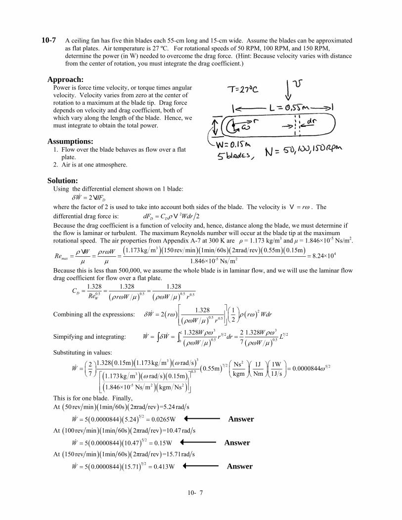
10-7 A ceiling fan has five thin blades each 55-cm long and 15-cm wide. Assume the blades can be approximated as flat plates. Air temperature is 27 ºC. For rotational speeds of 50 RPM, 100 RPM, and 150 RPM, determine the power (in W) needed to overcome the drag force. (Hint: Because velocity varies with distance from the center of rotation, you must integrate the drag coefficient.)
Approach:
Power is force time velocity, or torque times angular velocity. Velocity varies from zero at the center of rotation to a maximum at the blade tip. Drag force depends on velocity and drag coefficient, both of which vary along the length of the blade. Hence, we must integrate to obtain the total power.
Assumptions:
1. Flow over the blade behaves as flow over a flat plate. 2. Air is at one atmosphere.
Solution:
Using the differential element shown on 1 blade: 2 DW dFδ = V where the factor of 2 is used to take into account both sides of the blade. The velocity is rω=V . The differential drag force is: 2 2D DdF C Wdrρ= V Because the drag coefficient is a function of velocity and, hence, distance along the blade, we must determine if the flow is laminar or turbulent. The maximum Reynolds number will occur at the blade tip at the maximum rotational speed. The air properties from Appendix A-7 at 300 K are ρ = 1.173 kg/m3 and µ = 1.846×10⁻⁵ Ns/m2.
( )( )( )( )( )( )34
-5 2
1.173kg m 150rev min 1min 60s 2πrad rev 0.55m 0.15m8.24×10
1.846×10 Ns mmaxW r WRe ρ ρ ωµ µ
= = = =V
Because this is less than 500,000, we assume the whole blade is in laminar flow, and we will use the laminar flow drag coefficient for flow over a flat plate.
( ) ( )0.5 0.5 0.5 0.5
1.328 1.328 1.328D
W
CRe r W W rρ ω µ ρω µ
= = =
Combining all the expressions: ( )( )
( )20.5 0.5
1.328 122
W r r WdW r
δ ω ρ ωρω µ
⎡ ⎤ ⎛ ⎞= ⎢ ⎥ ⎜ ⎟⎝ ⎠⎢ ⎥⎣ ⎦
r
Simpifying and integrating: ( ) ( )
3 35 2 7 2
0.5 0.50
1.328 2 1.3287
L W WW W r dr LW W
ρω ρωδρω µ ρω µ
= = =∫ ∫
Substituting in values:
( )( )( )
( )( )( )( )( )
( )33 2
7 2 5 20.53
-5 2 2
1.328 0.15m 1.173kg m rad s2 Ns 1J0.55m 0.00008447 kgm Nm1.173kg m rad s 0.15m
1.846×10 Ns m kgm Ns
Wω 1W
1J sω
ω
⎛ ⎞ ⎛ ⎞⎛ ⎞ ⎛ ⎞= =⎜ ⎟ ⎜ ⎟⎜ ⎟ ⎜ ⎟⎝ ⎠ ⎝ ⎠⎡ ⎤ ⎝ ⎠⎝ ⎠
⎢ ⎥⎢ ⎥⎣ ⎦
This is for one blade. Finally, At ( )( )( )50 rev min 1min 60s 2πrad rev =5.24 rad s
( )( )5 25 0.0000844 5.24 0.0265WW = = Answer At ( ) ( )( )100rev min 1min 60s 2πrad rev =10.47 rad s
( )( )5 25 0.0000844 10.47 0.15WW = = Answer At ( )( )( )150rev min 1min 60s 2πrad rev =15.71rad s
( )( )5 25 0.0000844 15.71 0.413WW = = Answer
10- 7
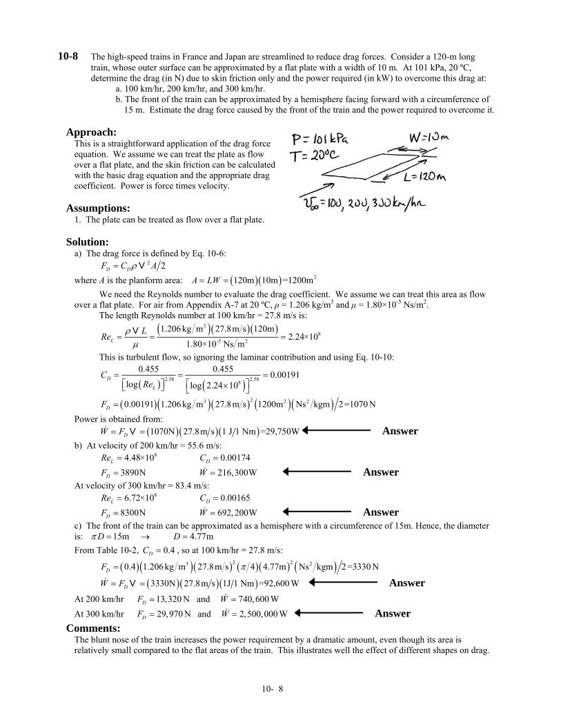
10-8 The high-speed trains in France and Japan are streamlined to reduce drag forces. Consider a 120-m long train, whose outer surface can be approximated by a flat plate with a width of 10 m. At 101 kPa, 20 ºC, determine the drag (in N) due to skin friction only and the power required (in kW) to overcome this drag at:
a. 100 km/hr, 200 km/hr, and 300 km/hr. b. The front of the train can be approximated by a hemisphere facing forward with a circumference of
15 m. Estimate the drag force caused by the front of the train and the power required to overcome it. Approach:
This is a straightforward application of the drag force equation. We assume we can treat the plate as flow over a flat plate, and the skin friction can be calculated with the basic drag equation and the appropriate drag coefficient. Power is force times velocity.
Assumptions:
1. The plate can be treated as flow over a flat plate.
Solution:
a) The drag force is defined by Eq. 10-6: 2 2D DF C Aρ= V where A is the planform area: ( )( ) 2120m 10m =1200mA LW= = We need the Reynolds number to evaluate the drag coefficient. We assume we can treat this area as flow over a flat plate. For air from Appendix A-7 at 20 ºC, ρ = 1.206 kg/m3 and µ = 1.80×10⁻⁵ Ns/m2. The length Reynolds number at 100 km/hr = 27.8 m/s is:
( )( )( )3
8-5 2
1.206kg m 27.8m s 120m2.24×10
1.80×10 Ns mLL
Reρµ
= = =V
This is turbulent flow, so ignoring the laminar contribution and using Eq. 10-10:
( ) ( )2.58 2.588
0.455 0.455 0.00191log log 2.24 10
D
L
CRe
= = =⎡ ⎤ ⎡ ⎤×⎣ ⎦ ⎣ ⎦
( )( )( ) ( )( )23 2 20.00191 1.206 kg m 27.8m s 1200m Ns kgm 2=1070 NDF = Power is obtained from: ( )( )( )1070N 27.8m s 1 J 1 Nm =29,750WDW F= =V Answer b) At velocity of 200 km/hr = 55.6 m/s: 84.48×10LRe = 0.00174DC =
3890NDF = 216,300WW = Answer At velocity of 300 km/hr = 83.4 m/s: 86.72×10LRe = 0.00165DC =
8300NDF = 692, 200WW = Answer c) The front of the train can be approximated as a hemisphere with a circumference of 15m. Hence, the diameter is: 15m 4.77mD Dπ = → = From Table 10-2, , so at 100 km/hr = 27.8 m/s: 0.4DC =
( )( )( ) ( )( ) ( )2 23 20.4 1.206kg m 27.8m s 4 4.77m Ns kgm 2 =3330 NDF π=
( )( )( )3330N 27.8m s 1J 1 Nm =92,600 WDW F= =V Answer
At 200 km/hr and 13,320 NDF = 740,600 WW =
At 300 km/hr and 29,970 NDF = 2,500,000 WW = Answer Comments:
The blunt nose of the train increases the power requirement by a dramatic amount, even though its area is relatively small compared to the flat areas of the train. This illustrates well the effect of different shapes on drag.
10- 8
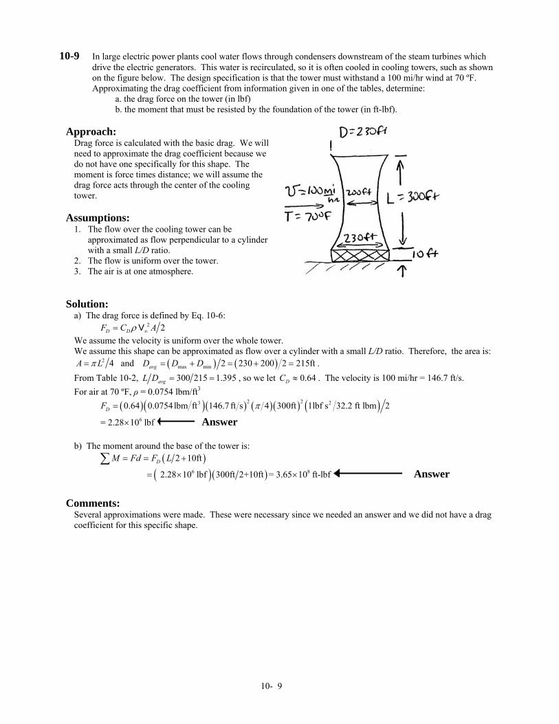
10-9 In large electric power plants cool water flows through condensers downstream of the steam turbines which drive the electric generators. This water is recirculated, so it is often cooled in cooling towers, such as shown on the figure below. The design specification is that the tower must withstand a 100 mi/hr wind at 70 ºF. Approximating the drag coefficient from information given in one of the tables, determine:
a. the drag force on the tower (in lbf) b. the moment that must be resisted by the foundation of the tower (in ft-lbf).
Approach:
Drag force is calculated with the basic drag. We will need to approximate the drag coefficient because we do not have one specifically for this shape. The moment is force times distance; we will assume the drag force acts through the center of the cooling tower.
Assumptions:
1. The flow over the cooling tower can be approximated as flow perpendicular to a cylinder with a small L/D ratio. 2. The flow is uniform over the tower. 3. The air is at one atmosphere.
Solution:
a) The drag force is defined by Eq. 10-6: 2 2D DF C Aρ ∞= V We assume the velocity is uniform over the whole tower. We assume this shape can be approximated as flow over a cylinder with a small L/D ratio. Therefore, the area is:
2 4A Lπ= and ( ) ( )max min 2 230 200 2 215ftavgD D D= + = + = . From Table 10-2, 300 215 1.395avgL D = = , so we let 0.64DC ≈ . The velocity is 100 mi/hr = 146.7 ft/s. For air at 70 ºF, ρ = 0.0754 lbm/ft3 ( )( )( ) ( )( ) ( )2 23 20.64 0.0754lbm ft 146.7 ft s 4 300ft 1lbf s 32.2 ft lbm 2DF π=
6= 2.28 10 lbf× Answer b) The moment around the base of the tower is: ( )2 10ftDM Fd F L= = +∑
( ) ( )6 8 2.28 10 lbf 300ft 2+10ft = 3.65 10 ft-lbf×= × Answer
Comments:
Several approximations were made. These were necessary since we needed an answer and we did not have a drag coefficient for this specific shape.
10- 9
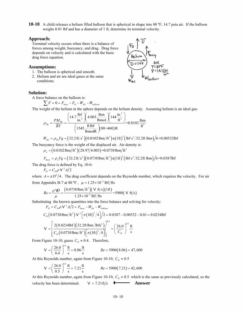
10-10 A child releases a helium filled balloon that is spherical in shape into 80 ºF, 14.7 psia air. If the balloon weighs 0.01 lbf and has a diameter of 1 ft, determine its terminal velocity.
Approach:
Terminal velocity occurs when there is a balance of forces among weight, buoyancy, and drag. Drag force depends on velocity and is calculated with the basic drag force equation.
Assumptions:
1. The balloon is spherical and smooth. 2. Helium and air are ideal gases at the same conditions.
Solution:
A force balance on the balloon is: 0 buoy D He balloonF F F W W= = − − −∑The weight of the helium in the sphere depends on the helium density. Assuming helium is an ideal gas:
( )
2
2 2
3
lbf lbm in.14.7 4.003 144lbmolin. ft lbm=0.0102
ft lbf ft1545 80+460 RlbmolR
HeHe
PMRT
ρ
⎛ ⎞⎛ ⎞⎛ ⎞⎜ ⎟⎜ ⎟⎜ ⎟
⎝ ⎠⎝ ⎠⎝ ⎠= =⎛ ⎞⎜ ⎟⎝ ⎠
( )( ) ( ) ( )32 3 232.2ft s 0.0102lbm ft π 1ft lbf s 32.2ft lbm 6=0.00532lbfHe HeW Vgρ= = The buoyancy force is the weight of the displaced air. Air density is: ( ) ( )3 30.0102lbm ft 28.97 4.003 =0.0738lbm ftaρ =
( )( ) ( ) ( )32 3 232.2ft s 0.0738lbm ft π 1ft lbf s 32.2ft lbm 6=0.0387lbfbuoy aF Vgρ= = The drag force is defined by Eq. 10-6: 2 2D DF C Aρ= V where 2 4A Dπ= . The drag coefficient depends on the Reynolds number, which requires the velocity. For air from Appendix B-7 at 80 ºF , 51.25 10 lbf ftsµ −= ×
( )( )( )
( )3
5
0.0738lbm ft ft s 1ft=5900 ft s
1.25 10 lbf ftsDRe ρµ −= =
×
VV V
Substituting the known quantities into the force balance and solving for velocity:
( ) ( )
2
23 2
2
0.0738lbm ft 1ft 4 2 0.0387 0.00532 0.01 0.0234lbf
D D buoy He balloon
D
F C A F W W
C
ρ
π
= = − −
⎡ ⎤ = − − =⎣ ⎦
V
V
( )( )( ) ( )
0.50.52
23
2 0.0234lbf 32.2ft lbm lbfs 26.0 fts0.0738lbm ft 1ft 4 DD
CC π
⎡ ⎤ ⎛ ⎞⎢ ⎥= = ⎜ ⎟⎢ ⎥⎡ ⎤ ⎝ ⎠⎢ ⎥⎣ ⎦⎣ ⎦
V
From Figure 10-10, guess . Therefore, 0.4DC ≈
0.526.0 ft ft8.06
0.4 s s⎛ ⎞= =⎜ ⎟⎝ ⎠
V ( )5900 8.06 47,600Re = =
At this Reynolds number, again from Figure 10-10, 0.5DC ≈
0.526.0 ft ft7.21
0.5 s s⎛ ⎞= =⎜ ⎟⎝ ⎠
V ( )5900 7.21 42,600Re = =
At this Reynolds number, again from Figure 10-10, 0.5DC ≈ which is the same as previously calculated, so the velocity has been determined. 7.21ft s=V Answer
10- 10
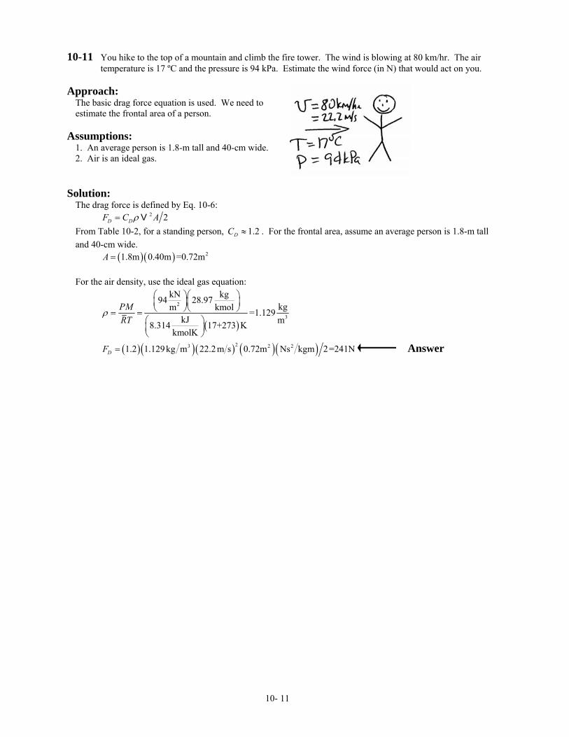
10-11 You hike to the top of a mountain and climb the fire tower. The wind is blowing at 80 km/hr. The air temperature is 17 ºC and the pressure is 94 kPa. Estimate the wind force (in N) that would act on you.
Approach:
The basic drag force equation is used. We need to estimate the frontal area of a person.
Assumptions:
1. An average person is 1.8-m tall and 40-cm wide. 2. Air is an ideal gas.
Solution:
The drag force is defined by Eq. 10-6: 2 2D DF C Aρ= V From Table 10-2, for a standing person, 1.2DC ≈ . For the frontal area, assume an average person is 1.8-m tall and 40-cm wide. ( )( ) 21.8m 0.40m =0.72mA = For the air density, use the ideal gas equation:
( )
2
3
kN kg94 28.97kgkmolm =1.129
kJ m8.314 17+273 KkmolK
PMRT
ρ
⎛ ⎞⎛ ⎞⎜ ⎟⎜ ⎟⎝ ⎠⎝ ⎠= =
⎛ ⎞⎜ ⎟⎝ ⎠
( )( ) ( ) ( )( )23 2 21.2 1.129kg m 22.2m s 0.72m Ns kgm 2=241NDF = Answer
10- 11
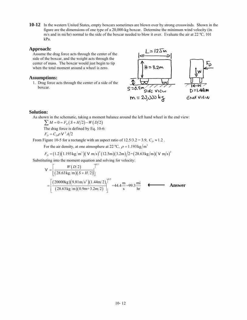
10-12 In the western United States, empty boxcars sometimes are blown over by strong crosswinds. Shown in the figure are the dimensions of one type of a 20,000-kg boxcar. Determine the minimum wind velocity (in m/s and in mi/hr) normal to the side of the boxcar needed to blow it over. Evaluate the air at 22 ºC, 101 kPa.
Approach:
Assume the drag force acts through the center of the side of the boxcar, and the weight acts through the center of mass. The boxcar would just begin to tip when the total moment around a wheel is zero.
Assumptions:
1. Drag force acts through the center of a side of the boxcar.
Solution:
As shown in the schematic, taking a moment balance around the left hand wheel in the end view: ( ) ( )0 2DM F S H W D= = + −∑ 2 The drag force is defined by Eq. 10-6: 2 2D DF C Aρ= V From Figure 10-5 for a rectangle with an aspect ratio of 12.5/3.2 = 3.9, 1.2DC ≈ . For the air density, at one atmosphere at 22 ºC, 31.193kg mρ =
( )( ) ( ) ( )( ) ( )( )2 231.2 1.193kg m m s 12.5m 3.2m 2= 28.63kg m m sDF = V V Substituting into the moment equation and solving for velocity:
( )
( )( )
0.52
28.63kg m 2W D
S H⎡ ⎤
= ⎢ ⎥+⎢ ⎥⎣ ⎦
V
( )( )( )( )( )
0.5220000kg 9.81m s 1.44m 2 m m=44.4 =99.328.63kg m 0.9m+3.2m 2 s hr
⎡ ⎤⎢ ⎥=⎢ ⎥⎣ ⎦
i Answer
10- 12
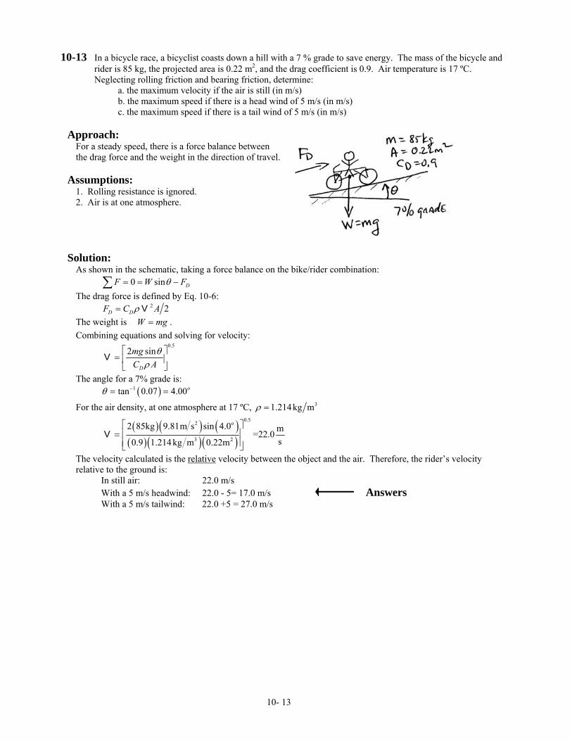
10-13 In a bicycle race, a bicyclist coasts down a hill with a 7 % grade to save energy. The mass of the bicycle and rider is 85 kg, the projected area is 0.22 m2, and the drag coefficient is 0.9. Air temperature is 17 ºC. Neglecting rolling friction and bearing friction, determine:
a. the maximum velocity if the air is still (in m/s) b. the maximum speed if there is a head wind of 5 m/s (in m/s) c. the maximum speed if there is a tail wind of 5 m/s (in m/s)
Approach:
For a steady speed, there is a force balance between the drag force and the weight in the direction of travel.
Assumptions:
1. Rolling resistance is ignored. 2. Air is at one atmosphere.
Solution:
As shown in the schematic, taking a force balance on the bike/rider combination: 0 sin DF W Fθ= = −∑ The drag force is defined by Eq. 10-6: 2 2D DF C Aρ= V The weight is W . mg=Combining equations and solving for velocity:
0.5
2 sin
D
mgC A
θρ
⎡ ⎤= ⎢ ⎥⎣ ⎦
V
The angle for a 7% grade is: ( )1 otan 0.07 4.00θ −= =
For the air density, at one atmosphere at 17 ºC, 31.214kg mρ =
( )( ) ( )( ) ( )( )
0.52 o
3 2
2 85kg 9.81m s sin 4.0 m=22.0s0.9 1.214kg m 0.22m
⎡ ⎤⎢ ⎥=⎢ ⎥⎣ ⎦
V
The velocity calculated is the relative velocity between the object and the air. Therefore, the rider’s velocity relative to the ground is: In still air: 22.0 m/s With a 5 m/s headwind: 22.0 - 5= 17.0 m/s Answers With a 5 m/s tailwind: 22.0 +5 = 27.0 m/s
10- 13
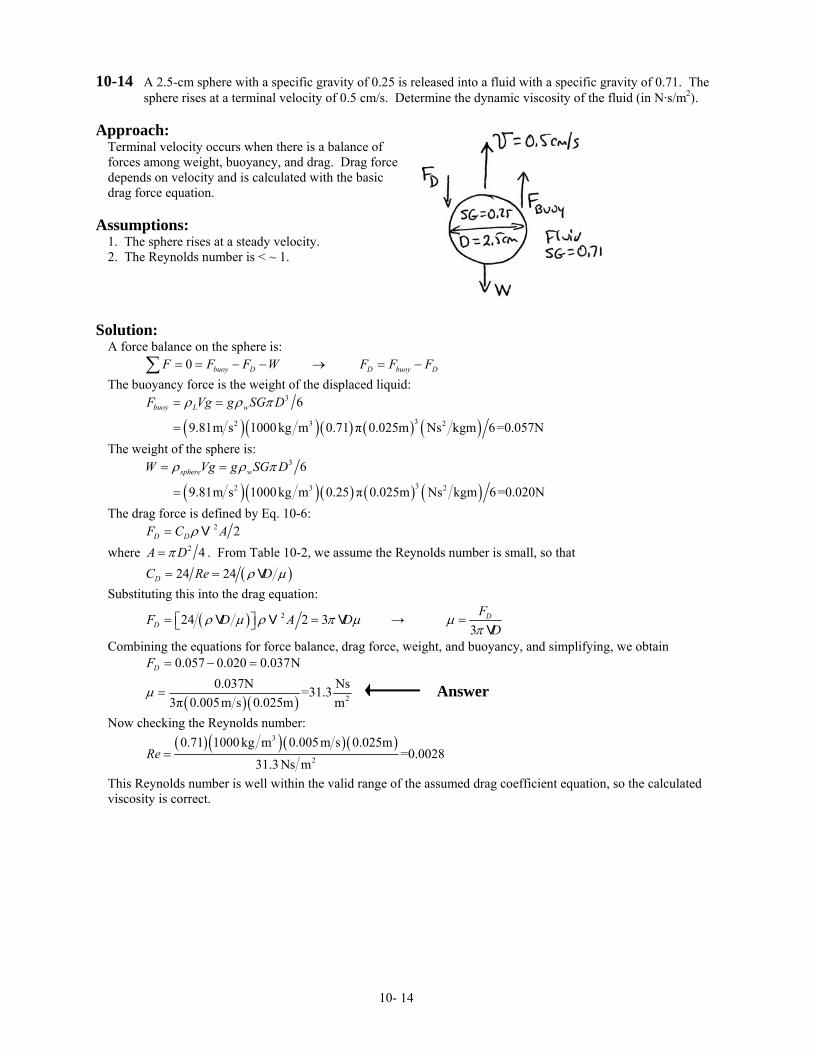
10-14 A 2.5-cm sphere with a specific gravity of 0.25 is released into a fluid with a specific gravity of 0.71. The sphere rises at a terminal velocity of 0.5 cm/s. Determine the dynamic viscosity of the fluid (in N·s/m2).
Approach:
Terminal velocity occurs when there is a balance of forces among weight, buoyancy, and drag. Drag force depends on velocity and is calculated with the basic drag force equation.
Assumptions:
1. The sphere rises at a steady velocity. 2. The Reynolds number is < ~ 1.
Solution:
A force balance on the sphere is: 0 buoy D D buoy DF F F W F F F= = − − → = −∑ The buoyancy force is the weight of the displaced liquid:
( )( )( ) ( ) ( )
3
32 3 2
6
9.81m s 1000kg m 0.71 π 0.025m Ns kgm 6=0.057N
buoy L wF Vg g SG Dρ ρ π= =
=
The weight of the sphere is:
( )( )( ) ( ) ( )
3
32 3 2
6
9.81m s 1000kg m 0.25 π 0.025m Ns kgm 6=0.020N
sphere wW Vg g SG Dρ ρ π= =
=
The drag force is defined by Eq. 10-6: 2 2D DF C Aρ= V where 2 4A Dπ= . From Table 10-2, we assume the Reynolds number is small, so that ( )24 24DC Re Dρ µ= = V Substituting this into the drag equation:
( ) 224 2 3DF D A Dρ µ ρ π µ= =⎡ ⎤⎣ ⎦V V V → 3
DFD
µπ
=V
Combining the equations for force balance, drag force, weight, and buoyancy, and simplifying, we obtain 0.057 0.020 0.037NDF = − =
( )( ) 2
0.037N Ns=31.33π 0.005m s 0.025m m
µ = Answer
Now checking the Reynolds number:
( )( )( )( )3
2
0.71 1000kg m 0.005m s 0.025m=0.0028
31.3 Ns mRe =
This Reynolds number is well within the valid range of the assumed drag coefficient equation, so the calculated viscosity is correct.
10- 14
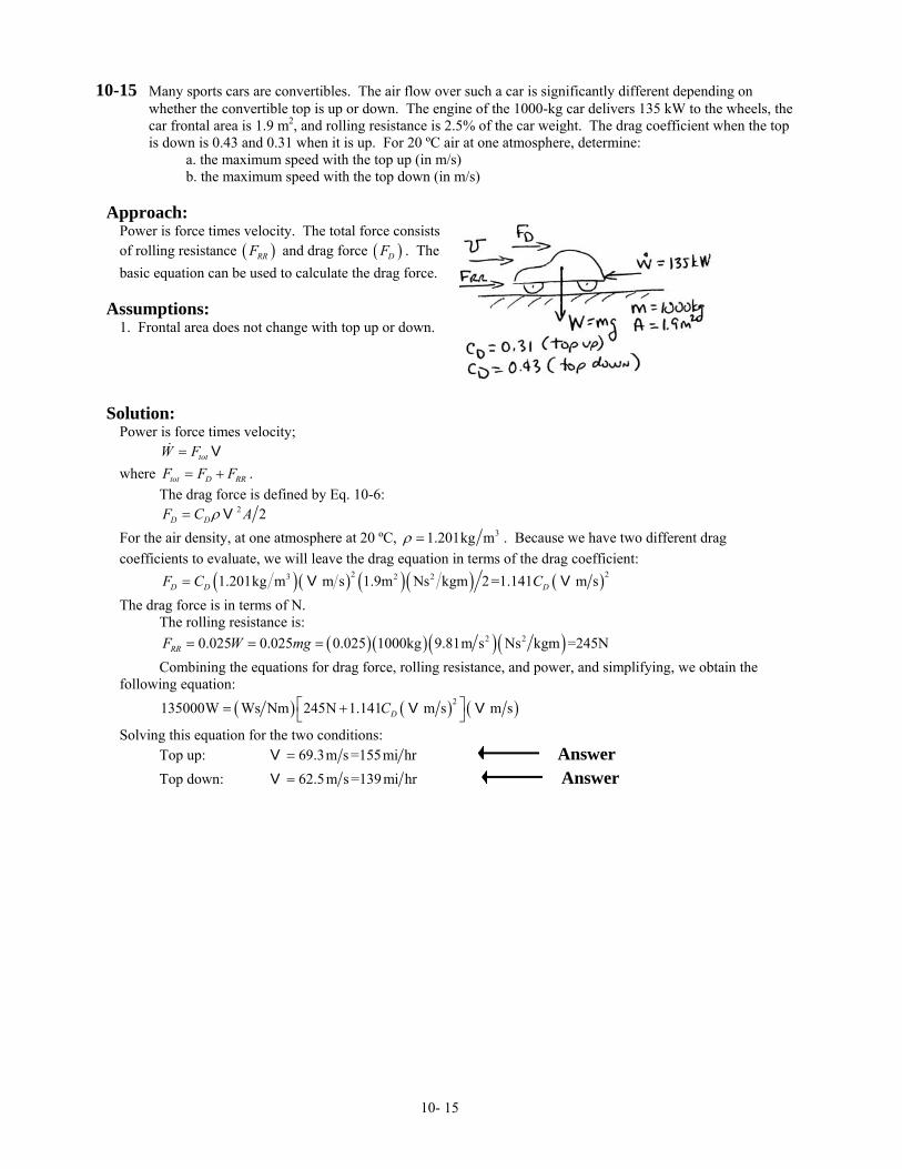
10-15 Many sports cars are convertibles. The air flow over such a car is significantly different depending on whether the convertible top is up or down. The engine of the 1000-kg car delivers 135 kW to the wheels, the car frontal area is 1.9 m2, and rolling resistance is 2.5% of the car weight. The drag coefficient when the top is down is 0.43 and 0.31 when it is up. For 20 ºC air at one atmosphere, determine:
a. the maximum speed with the top up (in m/s) b. the maximum speed with the top down (in m/s)
Approach:
Power is force times velocity. The total force consists of rolling resistance ( )RRF and drag force ( )DF . The basic equation can be used to calculate the drag force.
Assumptions:
1. Frontal area does not change with top up or down.
Solution:
Power is force times velocity; totW F= Vwhere tot D RRF F F= + . The drag force is defined by Eq. 10-6: 2 2D DF C Aρ= V For the air density, at one atmosphere at 20 ºC, 31.201kg mρ = . Because we have two different drag coefficients to evaluate, we will leave the drag equation in terms of the drag coefficient: ( ) ( ) ( )( ) ( )2 23 2 21.201kg m m s 1.9m Ns kgm 2 =1.141 m sD D DF C C= V V The drag force is in terms of N. The rolling resistance is: ( )( )( )( )2 20.025 0.025 0.025 1000kg 9.81m s Ns kgm =245NRRF W mg= = = Combining the equations for drag force, rolling resistance, and power, and simplifying, we obtain the following equation: ( ) ( ) ( )2135000W Ws Nm 245N 1.141 m s m sDC⎡ ⎤= +⎣ ⎦V V
Solving this equation for the two conditions: Top up: 69.3m s =155mi hr=V Answer Top down: 62.5m s =139mi hr=V Answer
10- 15

10-16 Wind speed is measured with an anemometer. A home-made anemometer can be constructed from a thin plate hinged on one end; when the plate is hung from the hinge, wind impinging on the plate will cause the plate to rotate around the hinge. The angular deflection is a measure of the wind speed. For a brass plate 20-mm wide and 50-mm long, derive a relationship between wind speed and angular deflection, θ. Assume the drag force on the plate depends only on the velocity component normal to the surface for angles less that about 40º and the air temperature is 25 °C. Determine:
a. the relationship between wind speed and angular deflection b. the thickness of brass needed for θ = 30º at a wind speed of 60 km/hr (in mm).
Approach:
In a steady wind, the angle θ is set by a moment balance between the wind force and the weight of the plate. The appropriate component of each force must be used.
Assumptions:
1. Air is at one atmosphere.
Solution:
a) A moment balance around the hinge, using the normal component of the drag force and the weight is: ,0 2D N N 2M F L W L= = −∑ The friction drag force is defined by Eq. 10-6, and using the normal component of velocity: ( )2
, cos 2D N D aF C Aρ θ= V where A is the area: A LD= The normal component of the weight is: sin sin sinN BW W mg LDtgθ θ ρ θ= = = Combining the expressions and solving for velocity:
1 2
2
2 sincos
B
D a
tgCρ θρ θ
⎛ ⎞= ⎜ ⎟⎝ ⎠
V Answer
b) Solving the above equation for thickness, t:
2 2cos
2 sinD a
B
Ct
gρ θρ θ
=V
The drag coefficient is obtained from Figure 10-5. With an aspect ratio of 0.05 0.02 2.5, 1.15DC= → ≈ For air at 25 ºC, ρa = 1.184 kg/m3. For brass, ρB = 8530 kg/m3.
( ) ( )
( ) ( )2 o 2
2 o
cos 301.15 1.184 60000 0.00421m=4.21mm2 8530 36009.81m s sin 30
mts
⎛ ⎞ ⎛ ⎞= =⎜ ⎟ ⎜ ⎟⎝ ⎠ ⎝ ⎠
Answer
Comments: If the angle becomes too large then this analysis will become invalid since the flow over the plate will become too different than flow perpendicular to a plate, and the drag coefficient will be affected.
10- 16
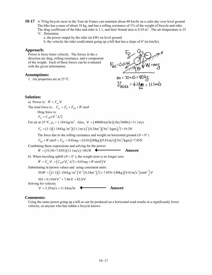
10-17 A 70-kg bicycle racer in the Tour de France can maintain about 40 km/hr on a calm day over level ground. The bike has a mass of about 10 kg, and has a rolling resistance of 1% of the weight of bicycle and rider. The drag coefficient of the bike and rider is 1.1, and their frontal area is 0.24 m2. The air temperature is 25 °C. Determine:
a. the power output by the rider (in kW) on level ground b. the velocity the rider could attain going up a hill that has a slope of 6º (in km/hr).
Approach:
Power is force times velocity. The forces in the x-direction are drag, rolling resistance, and a component of the weight. Each of these forces can be evaluated with the given information.
Assumptions:
1. Air properties are at 25 ºC.
Solution:
a) Power is: totW F= VThe total force is: sintot D RRF F F W θ= + + Drag force is: 2 2D DF C Aρ= V For air at 25 ºC, ρa = 1.184 kg/m3. Also, ( )( )40000 mi hr 1hr 3600s =11.1m s=V
( )( )( ) ( )( )23 2 21.1 1.184kg m 11.1m s 0.24m Ns kgm 2=19.3NDF =
The force due to the rolling resistance and weight on horizontal ground ( o0θ = ) ( )( )( )( )2sin 0.01 0.01 80kg 9.81m s Ns kgm =7.85NRR RRF W F mgθ+ = = = Combining these expressions and solving for the power: ( )( )19.3N+7.85N 11.1m s =301WW = Answer
b) When traveling uphill ( ), the weight term is no longer zero o6θ = ( )2 2 0.01 sintot DW F C A mg Wρ θ∞= = + +V V V Substituting in known values and using consistent units:
( )( ) ( ) ( )( )3 2 2 2 o
3
301 1.1 1.184 kg m 0.24m 2 7.85N+ 80kg 9.81m s sin6
301 0.1564 7.86 82.0
W ⎡ ⎤= +⎣ ⎦= + +
V V
V V V
Solving for velocity 3.29m s 11.8km hr= =V Answer
Comments: Using the same power going up a hill as can be produced on a horizontal road results in a significantly lower velocity, as anyone who has ridden a bicycle knows.
10- 17
10-18 Assume the bicycle rider in Problem P 10-17 adds a fairing to streamline his bike and body. The drag coefficient is reduced to 0.24 but the frontal area is increased to 0.29 m2. From the power the rider can produce, estimate the new speed (in km/hr) the rider can maintain on level ground.
Approach:
We use the equation developed in part (b) of Problem P10-17 to obtain the new speed.
Assumptions:
1. Air properties are at 25 ºC, 1 atm.
Solution:
We developed the equation: ( )2 2 0.01 sintot DW F C A mg Wρ θ= = + +V V V
On horizontal ground, . Using the variable values obtained in Problem P10-17, with the new drag coefficient and frontal area:
o0θ =
( )( ) ( ) ( )( )3 2 2 2 o
3
301 0.24 1.184kg m 0.29m 2 7.85N+ 80kg 9.81m s sin0
301 0.0412 7.86
W ⎡ ⎤= +⎣ ⎦= +
V V
V V
16.2m s 58.2km hr= =V Answer
Comments: This velocity is a significant increase from the 40 km/hr obtained without the fairing. The effect of streamlining is well illustrated by this comparison.
10- 18
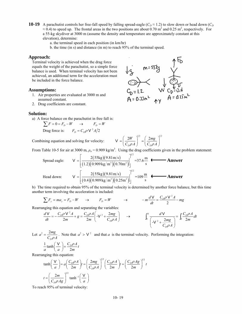
10-19 A parachutist controls her free-fall speed by falling spread-eagle (CD ≈ 1.2) to slow down or head down (CD ≈ 0.4) to speed up. The frontal areas in the two positions are about 0.70 m2 and 0.25 m2, respectively. For a 55-kg skydiver at 3000 m (assume the density and temperature are approximately constant at this elevation), determine:
a. the terminal speed in each position (in km/hr) b. the time (in s) and distance (in m) to reach 95% of the terminal speed.
Approach:
Terminal velocity is achieved when the drag force equals the weight of the parachutist, so a simple force balance is used. When terminal velocity has not been achieved, an additional term for the acceleration must be included in the force balance.
Assumptions:
1. Air properties are evaluated at 3000 m and assumed constant. 2. Drag coefficients are constant.
Solution:
a) A force balance on the parachutist in free fall is: 0 D DF F W F W= = − → =∑
Drag force is: 2 2D DF C Aρ= V
Combining equation and solving for velocity: 1 2 1 2
2 2
D D
W mgC A C Aρ ρ
⎛ ⎞ ⎛ ⎞= =⎜ ⎟ ⎜ ⎟⎝ ⎠ ⎝ ⎠
V
From Table 10-5 for air at 3000 m, ρa = 0.909 kg/m3. Using the drag coefficients given in the problem statement:
Spread eagle: ( )( )
( )( )( )
1 2
3 2
2 55kg 9.81m s m=37.6s1.2 0.909kg m 0.70m
⎡ ⎤⎢ ⎥=⎢ ⎥⎣ ⎦
V Answer
Head down: ( )( )
( )( )( )
1 2
3 2
2 55kg 9.81m s m=109s0.4 0.909kg m 0.25m
⎡ ⎤⎢ ⎥=⎢ ⎥⎣ ⎦
V Answer
b) The time required to obtain 95% of the terminal velocity is determined by another force balance, but this time another term involving the acceleration is included:
2
2D
y y D DC AdF ma F W F W m mg
dtρ
= = − → = → − = −∑ VV
Rearranging this equation and separating the variables:
2
2
0 02
22 2 22
tD D D
D
D
C A C A C Ad mg dg dtdt m m C A mmg
C A
ρ ρρ
ρ
⎛ ⎞= − + = + → =⎜ ⎟
⎛ ⎞⎝ ⎠ +⎜ ⎟⎝ ⎠
∫ ∫VVV V-V
-V
ρ
Let 2 2
D
mgaC Aρ
= . Note that and that a is the terminal velocity. Performing the integration: 2a > V 2
1 tanh2DC A t
a a mρ⎛ ⎞ =⎜ ⎟
⎝ ⎠
V
Rearranging this equation:
1 2 1 22tanh
2 2D D
D
C A C A C Agmga t ta m C A m m
ρ ρρ
⎛ ⎞⎛ ⎞ ⎛ ⎞ ⎛ ⎞⎛ ⎞ = = =⎜ ⎟⎜ ⎟ ⎜ ⎟ ⎜ ⎟ ⎜ ⎟⎝ ⎠ ⎝ ⎠ ⎝ ⎠ ⎝ ⎠⎝ ⎠
V2
D tρ
1 2
12 tanhD
mtC Ag aρ
−⎛ ⎞ ⎛ ⎞= ⎜ ⎟ ⎜ ⎟⎝ ⎠⎝ ⎠
V
To reach 95% of terminal velocity:
10- 19
Spread eagle:
( )( )( )( )( )
( ) ( ) ( )1 2
-1 -13 2
2 55kgtanh 0.95 = 3.832s tanh 0.95 =7.02s
1.2 0.909kg m 0.70m 9.81m st
⎡ ⎤⎢ ⎥=⎢ ⎥⎣ ⎦
Answer
Head down:
( )( )( )( )( )
( ) ( ) ( )1 2
-1 -13 2
2 55kgtanh 0.95 = 11.11s tanh 0.95 =20.3s
0.4 0.909kg m 0.25m 9.81m st
⎡ ⎤⎢ ⎥=⎢ ⎥⎣ ⎦
Answer
For the distance traveled, we solve the equation above for velocity and integrate with respect to time:
1 2
tanh2
DC Aga tmρ⎡ ⎤⎛ ⎞= ⎢ ⎥⎜ ⎟
⎝ ⎠⎢ ⎥⎣ ⎦V
Because dy dt=V
1 2 1 2
1 20 0 0tanh log cosh
2 22
y t t D D
D
C Ag C Agay dy dt a t tm mC Ag
m
ρ ρρ
⎧ ⎫⎡ ⎤ ⎡ ⎤⎪ ⎪⎛ ⎞ ⎛ ⎞= = = =⎢ ⎥ ⎢ ⎥⎨ ⎬⎜ ⎟ ⎜ ⎟⎝ ⎠ ⎝ ⎠⎛ ⎞⎢ ⎥ ⎢ ⎥⎪ ⎪⎣ ⎦ ⎣ ⎦⎩ ⎭⎜ ⎟
⎝ ⎠
∫ ∫ ∫V
Spread eagle: ( )37.6 m s 1log cosh 7.02 72.8m1 3.832s
3.832s
y s⎧ ⎫
⎬⎡ ⎤⎛ ⎞= =⎨ ⎜ ⎟⎢ ⎥⎛ ⎞ ⎝ ⎠⎣ ⎦⎩ ⎭⎜ ⎟
⎝ ⎠
Answer
Head down: ( )109m s 1log cosh 20.3 610m1 11.11s
11.11s
y s⎧ ⎫
⎬⎡ ⎤⎛ ⎞= =⎨ ⎜ ⎟⎢ ⎥⎛ ⎞ ⎝ ⎠⎣ ⎦⎩ ⎭⎜ ⎟
⎝ ⎠
Answer
Comments: The constant drag coefficient assumption is reasonable, since for blunt bodies, after a certain Reynolds number the drag coefficient does not vary much.
10- 20
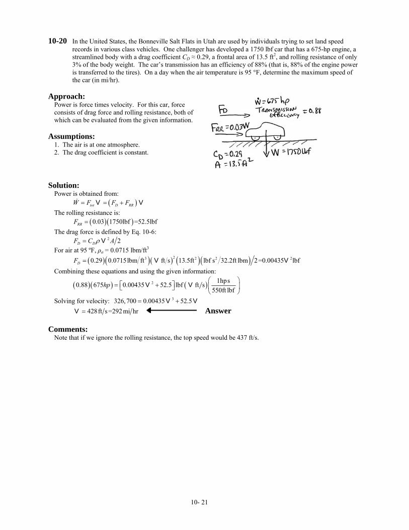
10-20 In the United States, the Bonneville Salt Flats in Utah are used by individuals trying to set land speed records in various class vehicles. One challenger has developed a 1750 lbf car that has a 675-hp engine, a streamlined body with a drag coefficient CD ≈ 0.29, a frontal area of 13.5 ft2, and rolling resistance of only 3% of the body weight. The car’s transmission has an efficiency of 88% (that is, 88% of the engine power is transferred to the tires). On a day when the air temperature is 95 °F, determine the maximum speed of the car (in mi/hr).
Approach:
Power is force times velocity. For this car, force consists of drag force and rolling resistance, both of which can be evaluated from the given information.
Assumptions:
1. The air is at one atmosphere. 2. The drag coefficient is constant.
Solution:
Power is obtained from: ( )tot D RRW F F F= = +V VThe rolling resistance is: ( )( )0.03 1750lbf =52.5lbfRRF =The drag force is defined by Eq. 10-6: 2 2D DF C Aρ= V For air at 95 ºF, ρa = 0.0715 lbm/ft3
( )( )( ) ( )( )23 2 20.29 0.0715lbm ft ft s 13.5ft lbf s 32.2ft lbm 2=0.00435 lbfDF = V V 2 Combining these equations and using the given information:
( )( ) ( )2 1hps0.88 675 0.00435 52.5 lbf ft s550ft lbf
hp⎛ ⎞
⎡ ⎤= + ⎜ ⎟⎣ ⎦⎝ ⎠
V V
Solving for velocity: 3326,700 0.00435 52.5= +V V 428ft s =292mi hr=V Answer
Comments: Note that if we ignore the rolling resistance, the top speed would be 437 ft/s.
10- 21
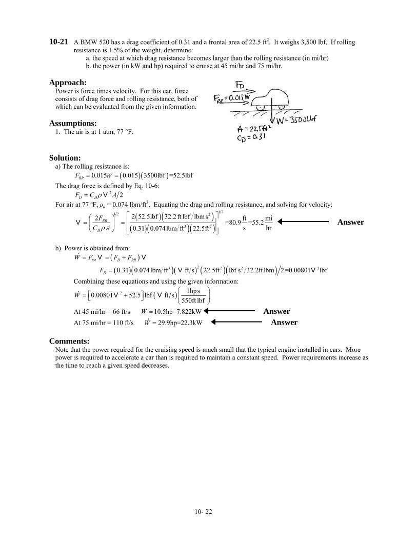
10-21 A BMW 520 has a drag coefficient of 0.31 and a frontal area of 22.5 ft2. It weighs 3,500 lbf. If rolling resistance is 1.5% of the weight, determine:
a. the speed at which drag resistance becomes larger than the rolling resistance (in mi/hr) b. the power (in kW and hp) required to cruise at 45 mi/hr and 75 mi/hr.
Approach:
Power is force times velocity. For this car, force consists of drag force and rolling resistance, both of which can be evaluated from the given information.
Assumptions:
1. The air is at 1 atm, 77 °F.
Solution:
a) The rolling resistance is: ( )( )0.015 0.015 3500lbf =52.5lbfRRF W= =The drag force is defined by Eq. 10-6: 2 2D DF C Aρ= V For air at 77 ºF, ρa = 0.074 lbm/ft3. Equating the drag and rolling resistance, and solving for velocity:
( )( )
( )( )( )
1 21 2 2
3 2
2 52.5lbf 32.2ft lbf lbms2 ft mi=80.9 =55.2s hr0.31 0.074lbm ft 22.5ft
RR
D
FC Aρ
⎡ ⎤⎛ ⎞⎢ ⎥= =⎜ ⎟⎢ ⎥⎝ ⎠ ⎣ ⎦
V Answer
b) Power is obtained from: ( )tot D RRW F F F= = +V V
( )( )( ) ( )( )23 2 20.31 0.074lbm ft ft s 22.5ft lbf s 32.2ft lbm 2=0.00801 lbfDF = V V 2 Combining these equations and using the given information:
( )2 1hps0.00801 52.5 lbf ft s550ft lbf
W⎛ ⎞
⎡ ⎤= + ⎜ ⎟⎣ ⎦⎝ ⎠
V V
At 45 mi/hr = 66 ft/s 10.5hp=7.822kWW = Answer At 75 mi/hr = 110 ft/s 29.9hp=22.3kWW = Answer
Comments: Note that the power required for the cruising speed is much small that the typical engine installed in cars. More power is required to accelerate a car than is required to maintain a constant speed. Power requirements increase as the time to reach a given speed decreases.
10- 22
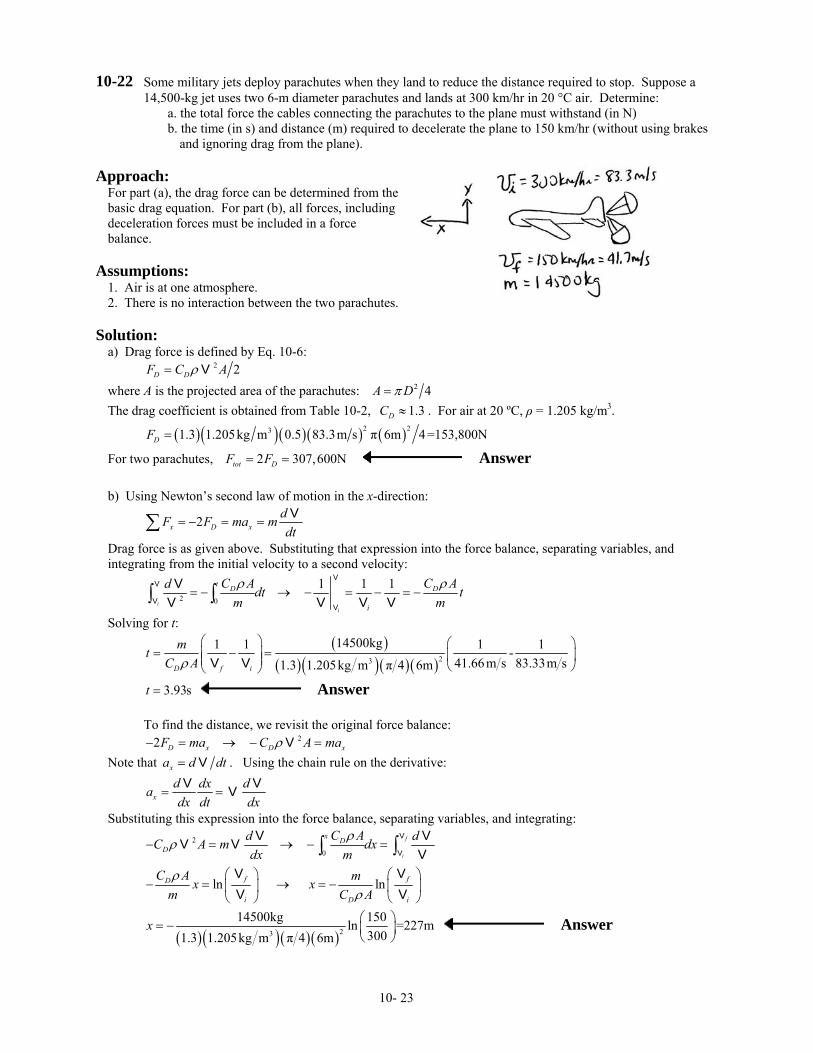
10-22 Some military jets deploy parachutes when they land to reduce the distance required to stop. Suppose a 14,500-kg jet uses two 6-m diameter parachutes and lands at 300 km/hr in 20 °C air. Determine:
a. the total force the cables connecting the parachutes to the plane must withstand (in N) b. the time (in s) and distance (m) required to decelerate the plane to 150 km/hr (without using brakes
and ignoring drag from the plane). Approach:
For part (a), the drag force can be determined from the basic drag equation. For part (b), all forces, including deceleration forces must be included in a force balance.
Assumptions:
1. Air is at one atmosphere. 2. There is no interaction between the two parachutes.
Solution:
a) Drag force is defined by Eq. 10-6: 2 2D DF C Aρ= V where A is the projected area of the parachutes: 2 4A Dπ= The drag coefficient is obtained from Table 10-2, 1.3DC ≈ . For air at 20 ºC, ρ = 1.205 kg/m3.
( )( )( )( ) ( )2 231.3 1.205kg m 0.5 83.3m s π 6m 4 =153,800NDF =
For two parachutes, 2 307,600Ntot DF F= = Answer b) Using Newton’s second law of motion in the x-direction:
2x D xdF F ma mdt
= − = =∑ V
Drag force is as given above. Substituting that expression into the force balance, separating variables, and integrating from the initial velocity to a second velocity:
2 0
1 1 1i
i
t D D
i
C A C Ad dt tm mρ ρ
= − → − = − = −∫ ∫V
V
VV
VV V VV
Solving for t:
( )
( )( )( ) ( )23
14500kg1 1 1 1-41.66m s 83.33m s1.3 1.205kg m π 4 6mD f i
mtC Aρ
⎛ ⎞ ⎛ ⎞= − =⎜ ⎟ ⎜ ⎟⎜ ⎟ ⎝ ⎠⎝ ⎠V V
3.93st = Answer To find the distance, we revisit the original force balance: 22 D x D xF ma C A maρ− = → − =V Note that xa d d= V t . Using the chain rule on the derivative:
xd dx dadx dt dx
= =V VV
Substituting this expression into the force balance, separating variables, and integrating:
2
0
f
i
x DD
C Ad dC A m dxdx m
ρρ− = → − =∫ ∫
V
V
V VV VV
ln lnf fD
i D
C A mx xm Cρ
ρ⎛ ⎞ ⎛ ⎞
− = → = −⎜ ⎟ ⎜ ⎟⎝ ⎠ ⎝ ⎠
V VV ViA
( )( )( )( )23
14500kg 150ln =227m3001.3 1.205kg m π 4 6m
x ⎛ ⎞= − ⎜ ⎟⎝ ⎠
Answer
10- 23
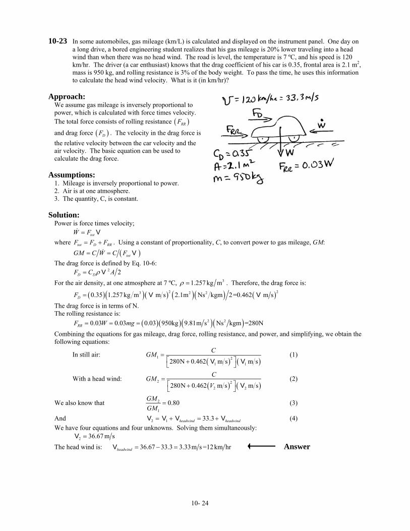
10-23 In some automobiles, gas mileage (km/L) is calculated and displayed on the instrument panel. One day on a long drive, a bored engineering student realizes that his gas mileage is 20% lower traveling into a head wind than when there was no head wind. The road is level, the temperature is 7 ºC, and his speed is 120 km/hr. The driver (a car enthusiast) knows that the drag coefficient of his car is 0.35, frontal area is 2.1 m2, mass is 950 kg, and rolling resistance is 3% of the body weight. To pass the time, he uses this information to calculate the head wind velocity. What is it (in km/hr)?
Approach:
We assume gas mileage is inversely proportional to power, which is calculated with force times velocity. The total force consists of rolling resistance ( )RRF
and drag force ( )DF . The velocity in the drag force is the relative velocity between the car velocity and the air velocity. The basic equation can be used to calculate the drag force.
Assumptions:
1. Mileage is inversely proportional to power. 2. Air is at one atmosphere. 3. The quantity, C, is constant.
Solution:
Power is force times velocity; totW F= Vwhere tot D RRF F F= + . Using a constant of proportionality, C, to convert power to gas mileage, GM: ( )totGM C W C F= = V The drag force is defined by Eq. 10-6: 2 2D DF C Aρ= V For the air density, at one atmosphere at 7 ºC, 31.257 kg mρ = . Therefore, the drag force is:
( )( )( ) ( )( ) ( )2 23 2 20.35 1.257 kg m m s 2.1m Ns kgm 2=0.462 m sDF = V V The drag force is in terms of N. The rolling resistance is: ( )( )( )( )2 20.03 0.03 0.03 950kg 9.81m s Ns kgm =280NRRF W mg= = = Combining the equations for gas mileage, drag force, rolling resistance, and power, and simplifying, we obtain the following equations:
In still air: ( ) ( )
1 21 1280N 0.462 m s m s
CGM =⎡ ⎤+⎣ ⎦V V
(1)
With a head wind: ( ) ( )
2 22 2280N 0.462 m s m s
CGMV
=⎡ ⎤+⎣ ⎦ V
(2)
We also know that 2
1
0.80GMGM
= (3)
And (4) 2 1 33.3headwind headwind= + = +V V V VWe have four equations and four unknowns. Solving them simultaneously: 2 36.67 m s=V The head wind is: 36.67 33.3 3.33m s =12km hrheadwind = − =V Answer
10- 24
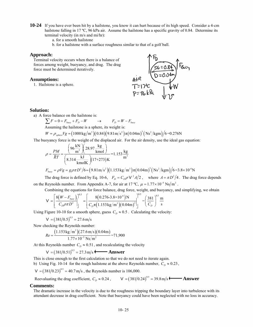
10-24 If you have ever been hit by a hailstone, you know it can hurt because of its high speed. Consider a 4-cm hailstone falling in 17 ºC, 96 kPa air. Assume the hailstone has a specific gravity of 0.84. Determine its terminal velocity (in m/s and mi/hr):
a. for a smooth hailstone b. for a hailstone with a surface roughness similar to that of a golf ball.
Approach:
Terminal velocity occurs when there is a balance of forces among weight, buoyancy, and drag. The drag force must be determined iteratively.
Assumptions:
1. Hailstone is a sphere.
Solution:
a) A force balance on the hailstone is: 0 buoy D D buoyF F F W F W F= = + − → = −∑ Assuming the hailstone is a sphere, its weight is: ( )( )( ) ( ) ( )33 2 21000kg m 0.84 9.81m s π 0.04m Ns kgm 6=0.276NsphereW Vgρ= = The buoyancy force is the weight of the displaced air. For the air density, use the ideal gas equation:
( )
2
3
kN kg96 28.97kgkmolm =1.153
kJ m8.314 17+273 KkmolK
PMRT
ρ
⎛ ⎞⎛ ⎞⎜ ⎟⎜ ⎟⎝ ⎠⎝ ⎠= =
⎛ ⎞⎜ ⎟⎝ ⎠
( )( ) ( ) ( )33 2 3 26 9.81m s 1.153kg m π 0.04m Ns kgm 6=3.8 10 NbuoyF Vg g Dρ ρπ= = = × -4
The drag force is defined by Eq. 10-6, 2 2D DF C Aρ= V , where 2 4A Dπ= . The drag force depends on the Reynolds number. From Appendix A-7, for air at 17 ºC, 5 21.77 10 Ns mµ −= × . Combining the equations for force balance, drag force, weight, and buoyancy, and simplifying, we obtain
( ) ( )
( )( )
0.50.5 0.5-4
2 23
8 0.276-3.8×10 N8 381 m=sπ 1.153kg m 0.04m
buoy
DD D
W F
CC D Cρπ
⎡ ⎤⎡ ⎤− ⎛ ⎞⎢ ⎥⎢ ⎥= = ⎜ ⎟⎢ ⎥⎢ ⎥ ⎝ ⎠⎣ ⎦ ⎣ ⎦
V
Using Figure 10-10 for a smooth sphere, guess 0.5DC ≈ . Calculating the velocity:
( )0.5381 0.5 27.6m s= =V Now checking the Reynolds number:
( )( )( )3
5 2
1.153kg m 27.6 m s 0.04m=71,900
1.77 10 Ns mRe −=
×
At this Reynolds number , and recalculating the velocity 0.51DC ≈
( )0.5381 0.51 27.3m s= =V Answer This is close enough to the first calculation so that we do not need to iterate again. b) Using Fig. 10-14 for the rough hailstone at the above Reynolds number, 0.23DC ≈ ,
( )0.5381 0.23 40.7 m s= =V , the Reynolds number is 106,000.
Reevaluating the drag coefficient, , 0.24DC ≈ ( )0.5381 0.24 39.8m s= =V Answer
Comments: The dramatic increase in the velocity is due to the roughness tripping the boundary layer into turbulence with its attendant decrease in drag coefficient. Note that buoyancy could have been neglected with no loss in accuracy.
10- 25
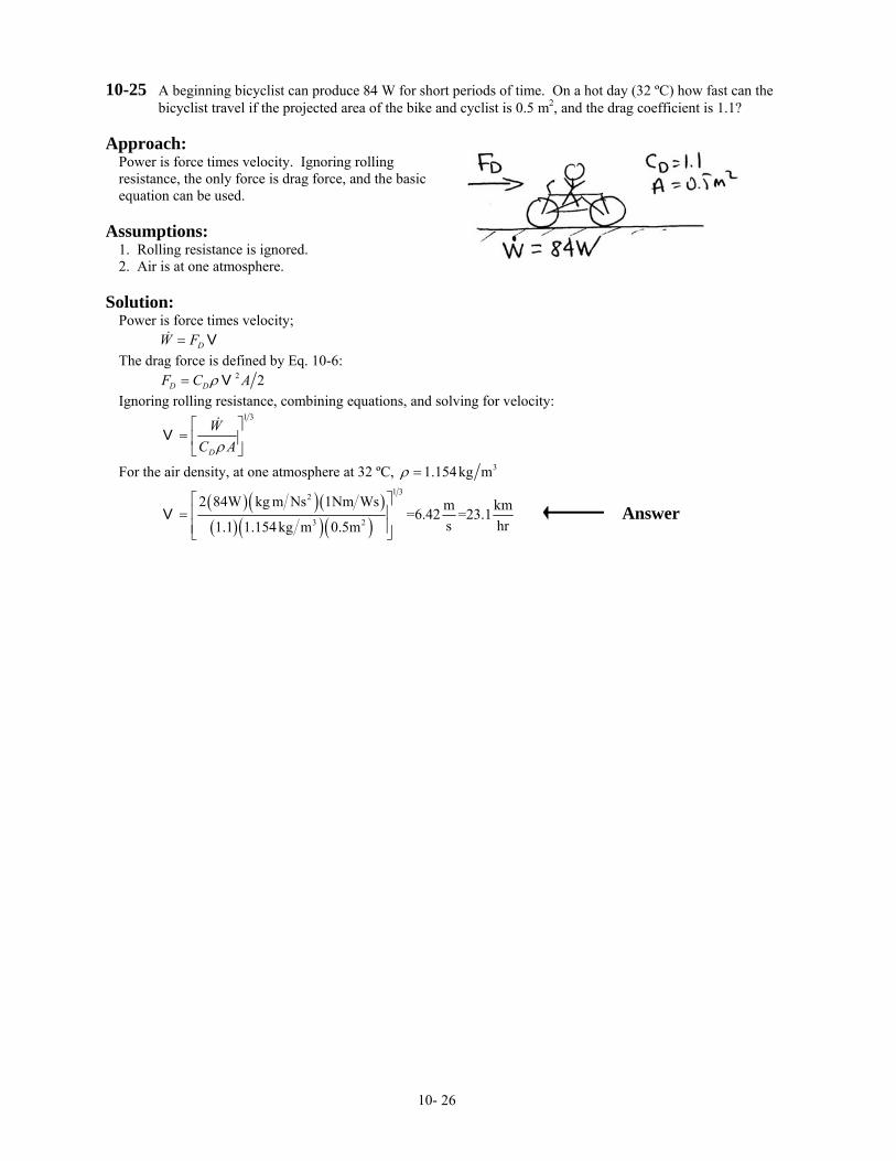
10-25 A beginning bicyclist can produce 84 W for short periods of time. On a hot day (32 ºC) how fast can the bicyclist travel if the projected area of the bike and cyclist is 0.5 m2, and the drag coefficient is 1.1?
Approach:
Power is force times velocity. Ignoring rolling resistance, the only force is drag force, and the basic equation can be used.
Assumptions:
1. Rolling resistance is ignored. 2. Air is at one atmosphere.
Solution:
Power is force times velocity; DW F= VThe drag force is defined by Eq. 10-6: 2 2D DF C Aρ= V Ignoring rolling resistance, combining equations, and solving for velocity:
1 3
D
WC Aρ⎡ ⎤
= ⎢ ⎥⎣ ⎦
V
For the air density, at one atmosphere at 32 ºC, 31.154kg mρ =
( )( )( )( )( )( )
1 32
3 2
2 84W kg m Ns 1Nm Ws m k=6.42 =23.1s h1.1 1.154kg m 0.5m
⎡ ⎤⎢ ⎥=⎢ ⎥⎣ ⎦
V mr
Answer
10- 26
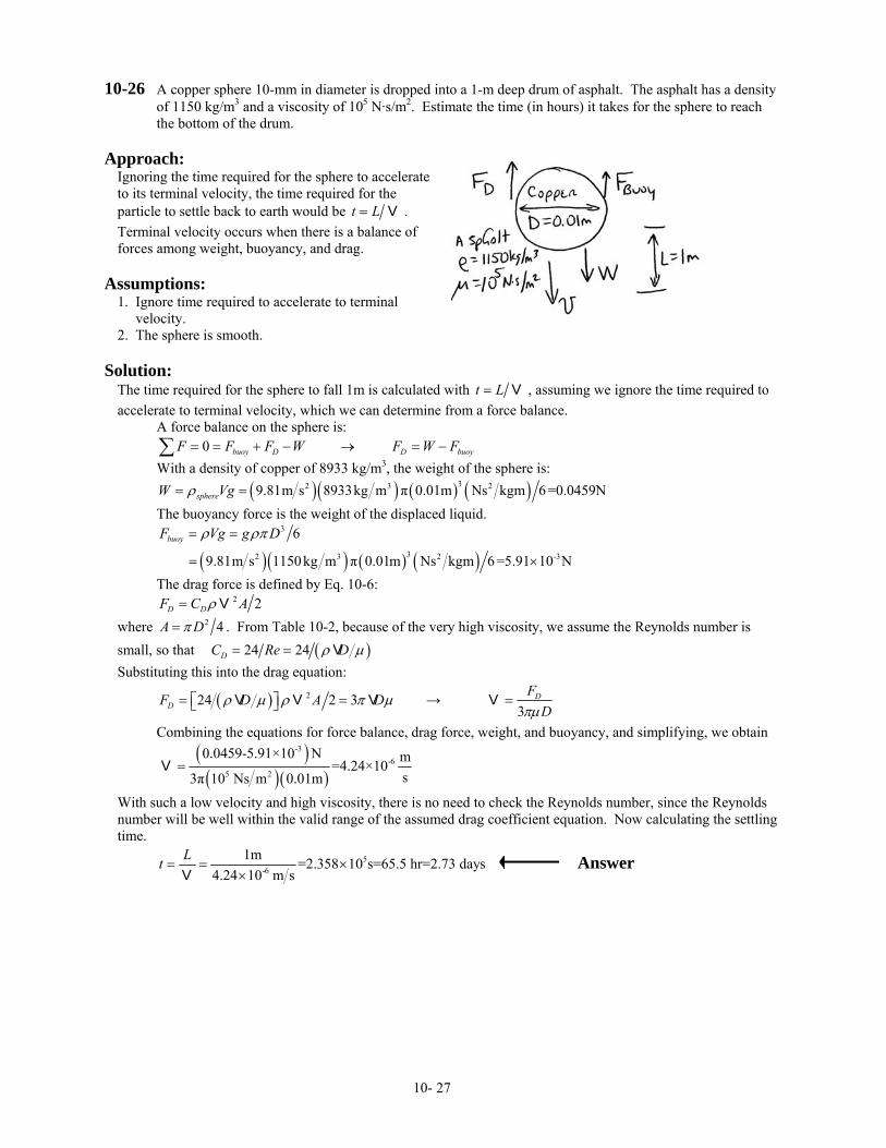
10-26 A copper sphere 10-mm in diameter is dropped into a 1-m deep drum of asphalt. The asphalt has a density of 1150 kg/m3 and a viscosity of 105 N·s/m2. Estimate the time (in hours) it takes for the sphere to reach the bottom of the drum.
Approach:
Ignoring the time required for the sphere to accelerate to its terminal velocity, the time required for the particle to settle back to earth would be t L= V . Terminal velocity occurs when there is a balance of forces among weight, buoyancy, and drag.
Assumptions:
1. Ignore time required to accelerate to terminal velocity. 2. The sphere is smooth.
Solution:
The time required for the sphere to fall 1m is calculated with t L= V , assuming we ignore the time required to accelerate to terminal velocity, which we can determine from a force balance. A force balance on the sphere is: 0 buoy D D buoyF F F W F W F= = + − → = −∑ With a density of copper of 8933 kg/m3, the weight of the sphere is: ( )( ) ( ) ( )32 3 29.81m s 8933kg m π 0.01m Ns kgm 6=0.0459NsphereW Vgρ= = The buoyancy force is the weight of the displaced liquid.
( )( ) ( ) ( )
3
32 3 2
6
9.81m s 1150kg m π 0.01m Ns kgm 6 =5.91 10 N
buoyF Vg g Dρ ρπ= =
= × -3
The drag force is defined by Eq. 10-6: 2 2D DF C Aρ= V where 2 4A Dπ= . From Table 10-2, because of the very high viscosity, we assume the Reynolds number is small, so that ( )24 24DC Re Dρ µ= = V Substituting this into the drag equation:
( ) 224 2 3DF D A Dρ µ ρ π µ= =⎡ ⎤⎣ ⎦V V V → 3
DFDπµ
=V
Combining the equations for force balance, drag force, weight, and buoyancy, and simplifying, we obtain
( )( )( )
-3-6
5 2
0.0459-5.91×10 N m=4.24×10s3π 10 Ns m 0.01m
=V
With such a low velocity and high viscosity, there is no need to check the Reynolds number, since the Reynolds number will be well within the valid range of the assumed drag coefficient equation. Now calculating the settling time.
5-6
1m =2.358 10 s=65.5 hr=2.73 days4.24 10 m s
Lt = = ××V
Answer
10- 27
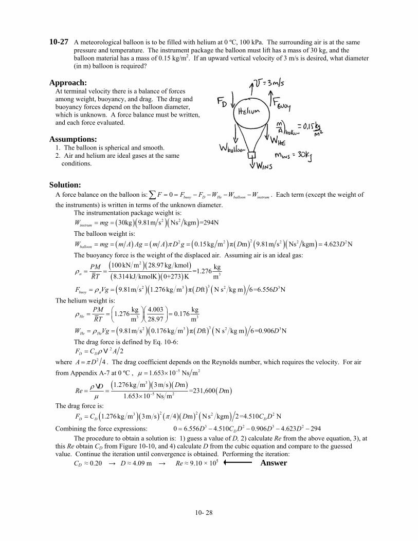
10-27 A meteorological balloon is to be filled with helium at 0 ºC, 100 kPa. The surrounding air is at the same pressure and temperature. The instrument package the balloon must lift has a mass of 30 kg, and the balloon material has a mass of 0.15 kg/m2. If an upward vertical velocity of 3 m/s is desired, what diameter (in m) balloon is required?
Approach:
At terminal velocity there is a balance of forces among weight, buoyancy, and drag. The drag and buoyancy forces depend on the balloon diameter, which is unknown. A force balance must be written, and each force evaluated.
Assumptions:
1. The balloon is spherical and smooth. 2. Air and helium are ideal gases at the same
conditions.
Solution:
A force balance on the balloon is: . Each term (except the weight of the instruments) is written in terms of the unknown diameter.
0 buoy D He balloon instrumF F F W W W= = − − − −∑
The instrumentation package weight is: ( )( )( )2 230kg 9.81m s Ns kgm =294NinstrumW mg= = The balloon weight is: ( ) ( ) ( ) ( ) ( )( )22 2 2 20.15kg m π m 9.81m s Ns kgm 4.623 NballoonW mg m A Ag m A D g D Dπ= = = = = 2 The buoyancy force is the weight of the displaced air. Assuming air is an ideal gas:
( )( )( )( )
2
3
100kN m 28.97 kg kmol kg=1.2768.314kJ kmolK 0+273 K ma
PMRT
ρ = =
( )( ) ( ) ( )32 3 29.81m s 1.276kg m π ft N s kg m 6=6.556 Nbuoy aF Vg D Dρ= = 3 The helium weight is:
3 3
kg 4.003 kg1.276 0.17628.97m mHe
PMRT
ρ ⎛ ⎞⎛ ⎞= = =⎜ ⎟⎜ ⎟⎝ ⎠⎝ ⎠
( )( ) ( ) ( )32 3 29.81m s 0.176kg m π ft N s kg m 6=0.906 NHe HeW Vg D Dρ= = 3 The drag force is defined by Eq. 10-6: 2 2D DF C Aρ= V where 2 4A Dπ= . The drag coefficient depends on the Reynolds number, which requires the velocity. For air from Appendix A-7 at 0 ºC , 5 21.653 10 Ns mµ −= ×
( )( )( )
( )3
5 2
1.276kg m 3m s m=231,600 m
1.653 10 Ns m
DDRe Dρµ −= =
×V
The drag force is: ( )( ) ( )( ) ( )2 23 21.276kg m 3m s 4 m Ns kgm 2=4.510 ND D DF C D C Dπ= 2
Combining the force expressions: 3 2 3 20 6.556 4.510 0.906 4.623 294DD C D D D= − − − − The procedure to obtain a solution is: 1) guess a value of D, 2) calculate Re from the above equation, 3), at this Re obtain CD from Figure 10-10, and 4) calculate D from the cubic equation and compare to the guessed value. Continue the iteration until convergence is obtained. Performing the iteration: CD ≈ 0.20 → D ≈ 4.09 m → Re ≈ 9.10 × 10⁵ Answer
10- 28
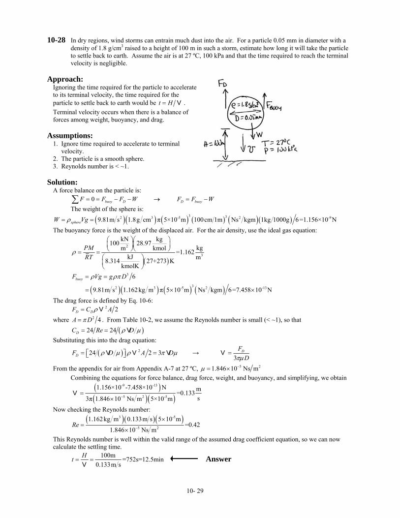
10-28 In dry regions, wind storms can entrain much dust into the air. For a particle 0.05 mm in diameter with a density of 1.8 g/cm3 raised to a height of 100 m in such a storm, estimate how long it will take the particle to settle back to earth. Assume the air is at 27 ºC, 100 kPa and that the time required to reach the terminal velocity is negligible.
Approach:
Ignoring the time required for the particle to accelerate to its terminal velocity, the time required for the particle to settle back to earth would be t H= V . Terminal velocity occurs when there is a balance of forces among weight, buoyancy, and drag.
Assumptions:
1. Ignore time required to accelerate to terminal velocity. 2. The particle is a smooth sphere. 3. Reynolds number is < ~1.
Solution:
A force balance on the particle is: 0 buoy D D buoyF F F W F F W= = − − → = −∑ The weight of the sphere is:
( )( ) ( ) ( ) ( )( )3 32 3 -5 29.81m s 1.8g cm π 5×10 m 100cm 1m Ns kgm 1kg 1000g 6=1.156×10 NsphereW Vgρ= = -9 The buoyancy force is the weight of the displaced air. For the air density, use the ideal gas equation:
( )
2
3
kN kg100 28.97kgkmolm =1.162
kJ m8.314 27+273 KkmolK
PMRT
ρ
⎛ ⎞⎛ ⎞⎜ ⎟⎜ ⎟⎝ ⎠⎝ ⎠= =
⎛ ⎞⎜ ⎟⎝ ⎠
( )( ) ( ) ( )
3
32 3 -5 2
6
9.81m s 1.162kg m π 5 10 m Ns kgm 6=7.458 10 N
buoyF Vg g Dρ ρπ= =
= × -13×
The drag force is defined by Eq. 10-6: 2 2D DF C Aρ= V where 2 4A Dπ= . From Table 10-2, we assume the Reynolds number is small (< ~1), so that ( )24 24DC Re Dρ µ= = V Substituting this into the drag equation:
( ) 224 2 3DF D A Dρ µ ρ π µ= =⎡ ⎤⎣ ⎦V V V → 3
DFDπµ
=V
From the appendix for air from Appendix A-7 at 27 ºC, 5 21.846 10 Ns mµ −= × Combining the equations for force balance, drag force, weight, and buoyancy, and simplifying, we obtain
( )( )( )
-9 -13
5 2 -5
1.156×10 -7.458×10 N m=0.133s3π 1.846 10 Ns m 5×10 m−
=×
V
Now checking the Reynolds number:
( )( )( )3 -5
5 2
1.162kg m 0.133m s 5 10 m=0.42
1.846 10 Ns mRe −
×=
×
This Reynolds number is well within the valid range of the assumed drag coefficient equation, so we can now calculate the settling time.
100m =752s=12.5min0.133m s
Ht = =V
Answer
10- 29

10-29 A 5-mm iron sphere is dropped into a tank of 17 ºC unused engine oil. Determine the sphere’s terminal velocity (in cm/s).
Approach:
Terminal velocity occurs when there is a balance of forces among weight, buoyancy, and drag. The drag force can be determined iteratively.
Assumptions:
1. Sphere is smooth.
Solution:
a) A force balance on the sphere is: 0 buoy D D buoyF F F W F W F= = + − → = −∑ With a density of iron of 7870 kg/m3, the weight of the sphere is: ( )( ) ( ) ( )33 2 27870kg m 9.81m s π 0.005m Ns kgm 6=5.053 10 NsphereW Vgρ= = × -3
The buoyancy force is the weight of the displaced oil. From Appendix A-6 for oil at 20 ºC, 3888.2kg mρ = , 4 28450 10 Ns mµ −= ×
( )( ) ( ) ( )33 2 3 26 9.81m s 888.2kg m π 0.005m Ns kgm 6=5.703 10 NbuoyF Vg g Dρ ρπ= = = × -4
The drag force is defined by Eq. 10-6, 2 2D DF C Aρ= V , where 2 4A Dπ= . The drag force depends on the Reynolds number. Combining the equations for force balance, drag force, weight, and buoyancy, and simplifying, we obtain
( ) ( )
( )( )
0.50.5 0.5-3 -4
2 33
8 5.053×10 -5.703×10 N8 0.752 m=sπ 888.2kg m 0.005m
buoy
DD D
W F
CC D Cρπ
⎡ ⎤⎡ ⎤− ⎛ ⎞⎢ ⎥⎢ ⎥= = ⎜ ⎟⎢ ⎥⎢ ⎥ ⎝ ⎠⎣ ⎦ ⎣ ⎦
V
The Reynolds number is:
( )( )( )
(3
4 2
888.2 kg m m s 0.005m=5.256 m s
8450 10 Ns mRe −=
×
VV )
To determine the terminal velocity, the procedure to use is: 1) guess CD using Figure 10-8, 2) calculate the velocity, 3) calculate the Reynolds number, 4) evaluate CD using Figure 10-8 and compare to the initial guess, 50 repeat the proceeding steps until converged. Guess 0. , calculate velocity 5DC ≈ ( )0.50.752 0.5 1.23m s= =V , calculate Reynolds number
( )5.256 1.23m s 6.46Re = = , reevaluate 6DC ≈ ; recalculate velocity ( )0.50.752 7 0.354 m s= =V , Reynolds
number . At this Reynolds number 1.86Re = 24 24 1.86 12.9DC Re= = = and ( )0.50.752 12.9 0.241m s= =V . Continuing several more steps in the iteration, we obtain 27.6 , DC ≈ 0.165m s=V , 0.868Re = Answer
Comments:
Note that if we had initially assumed that the Reynolds number would be < ~1, then we could have used 24DC = Re to obtain an analytic solution. One the terminal velocity had been determined, we would have
needed to check the Reynolds number to confirm the assumption.
10- 30
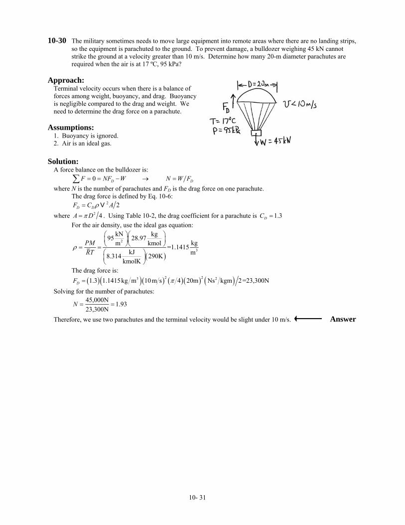
10-30 The military sometimes needs to move large equipment into remote areas where there are no landing strips, so the equipment is parachuted to the ground. To prevent damage, a bulldozer weighing 45 kN cannot strike the ground at a velocity greater than 10 m/s. Determine how many 20-m diameter parachutes are required when the air is at 17 ºC, 95 kPa?
Approach:
Terminal velocity occurs when there is a balance of forces among weight, buoyancy, and drag. Buoyancy is negligible compared to the drag and weight. We need to determine the drag force on a parachute.
Assumptions:
1. Buoyancy is ignored. 2. Air is an ideal gas.
Solution:
A force balance on the bulldozer is: 0 D DF NF W N W F= = − → =∑ where N is the number of parachutes and FD is the drag force on one parachute. The drag force is defined by Eq. 10-6: 2 2D DF C Aρ= V where 2 4A Dπ= . Using Table 10-2, the drag coefficient for a parachute is 1.3DC = For the air density, use the ideal gas equation:
( )
2
3
kN kg95 28.97kgkmolm =1.1415
kJ m8.314 290KkmolK
PMRT
ρ
⎛ ⎞⎛ ⎞⎜ ⎟⎜ ⎟⎝ ⎠⎝ ⎠= =⎛ ⎞⎜ ⎟⎝ ⎠
The drag force is: ( )( )( ) ( )( ) ( )2 23 21.3 1.1415kg m 10m s 4 20m Ns kgm 2=23,300NDF π= Solving for the number of parachutes:
45,000N 1.9323,300N
N = =
Therefore, we use two parachutes and the terminal velocity would be slight under 10 m/s. Answer
10- 31
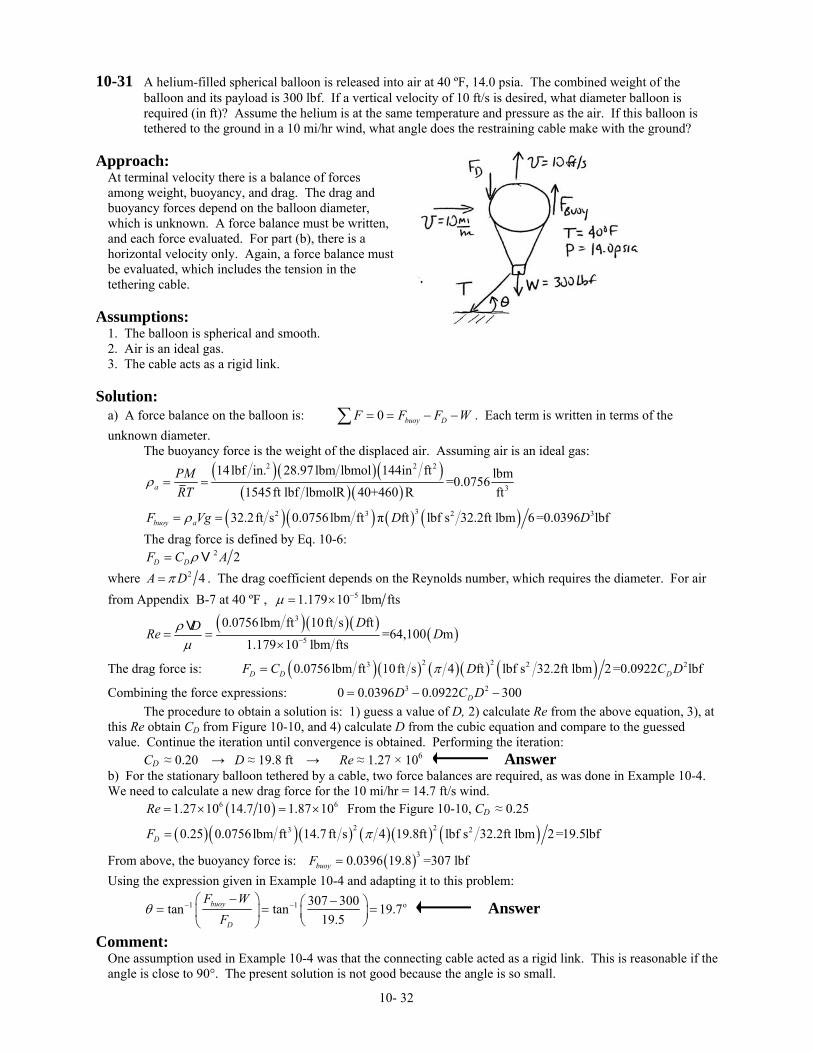
10-31 A helium-filled spherical balloon is released into air at 40 ºF, 14.0 psia. The combined weight of the balloon and its payload is 300 lbf. If a vertical velocity of 10 ft/s is desired, what diameter balloon is required (in ft)? Assume the helium is at the same temperature and pressure as the air. If this balloon is tethered to the ground in a 10 mi/hr wind, what angle does the restraining cable make with the ground?
Approach:
At terminal velocity there is a balance of forces among weight, buoyancy, and drag. The drag and buoyancy forces depend on the balloon diameter, which is unknown. A force balance must be written, and each force evaluated. For part (b), there is a horizontal velocity only. Again, a force balance must be evaluated, which includes the tension in the tethering cable.
Assumptions:
1. The balloon is spherical and smooth. 2. Air is an ideal gas. 3. The cable acts as a rigid link.
Solution:
a) A force balance on the balloon is: 0 buoy DF F F W= = − −∑ . Each term is written in terms of the unknown diameter. The buoyancy force is the weight of the displaced air. Assuming air is an ideal gas:
( )( )( )
( )( )
2 2 2
3
14lbf in. 28.97 lbm lbmol 144in ft lbm=0.07561545ft lbf lbmolR 40+460 R fta
PMRT
ρ = =
( )( ) ( ) ( )32 3 232.2ft s 0.0756lbm ft π ft lbf s 32.2ft lbm 6=0.0396 lbfbuoy aF Vg D Dρ= = 3 The drag force is defined by Eq. 10-6: 2 2D DF C Aρ= V where 2 4A Dπ= . The drag coefficient depends on the Reynolds number, which requires the diameter. For air from Appendix B-7 at 40 ºF , 51.179 10 lbm ftsµ −= ×
( )( )( )
( )3
5
0.0756lbm ft 10ft s ft=64,100 m
1.179 10 lbm fts
DDRe Dρµ −= =
×V
The drag force is: ( )( ) ( )( ) ( )2 23 20.0756lbm ft 10ft s 4 ft lbf s 32.2ft lbm 2 =0.0922 lbfD D DF C D C Dπ= 2
Combining the force expressions: 3 20 0.0396 0.0922 300DD C D= − − The procedure to obtain a solution is: 1) guess a value of D, 2) calculate Re from the above equation, 3), at this Re obtain CD from Figure 10-10, and 4) calculate D from the cubic equation and compare to the guessed value. Continue the iteration until convergence is obtained. Performing the iteration: CD ≈ 0.20 → D ≈ 19.8 ft → Re ≈ 1.27 × 10⁶ Answer b) For the stationary balloon tethered by a cable, two force balances are required, as was done in Example 10-4. We need to calculate a new drag force for the 10 mi/hr = 14.7 ft/s wind. ( )61.27 10 14.7 10 1.87 10Re = × = × 6 From the Figure 10-10, CD ≈ 0.25
( )( )( ) ( ) ( ) ( )2 23 20.25 0.0756lbm ft 14.7 ft s 4 19.8ft lbf s 32.2ft lbm 2=19.5lbfDF π=
From above, the buoyancy force is: ( )30.0396 19.8 =307 lbfbuoyF =Using the expression given in Example 10-4 and adapting it to this problem:
1 1 o=307 300tan tan 19.7
19.5buoy
D
F WF
θ − −−⎛ ⎞ −⎛ ⎞= =⎜ ⎟ ⎜ ⎟⎝ ⎠⎝ ⎠
Answer
Comment: One assumption used in Example 10-4 was that the connecting cable acted as a rigid link. This is reasonable if the angle is close to 90°. The present solution is not good because the angle is so small.
10- 32

10-32 A 40-mm ping pong ball weighing 0.025 N is released from the bottom of a 4-m deep swimming pool
whose temperature is 20 ºC. Ignoring the time to reach terminal velocity, how long does the ball take to reach the pool surface (in s)?
Approach:
The time required for the ball to reach the surface of the swimming pole is obtained by dividing the depth by the velocity. Ignoring the time required to reach terminal velocity, terminal velocity occurs when there is a balance of forces among weight, buoyancy, and drag. The drag force must be determined iteratively.
Assumptions:
1. Ignore the time required to accelerate to terminal velocity.
Solution:
Ignoring the time required to accelerate the ping pong ball to its terminal velocity, the time required for the sphere to reach the surface is t H= V . Hence, we need to determine the terminal velocity. A force balance on the ping pong ball is: 0 buoy D D buoyF F F W F F W= = − − → = −∑ The buoyancy force is the weight of the displaced liquid. For water from Appendix A-6 at 20ºC, ρ = 998.2 kg/m3 and 4 29.85 10 Ns mµ −= × .
( )( ) ( ) ( )33 2 3 26 9.81m s 998.2kg m π 0.04m Ns kgm 6=0.328NbuoyF Vg g Dρ ρπ= = =
The drag force is defined by Eq. 10-6, 2 2D DF C Aρ= V , where 2 4A Dπ= . Combining the equations for force balance, drag force, weight, and buoyancy, and simplifying, we obtain
( ) ( )
( )( )
0.50.5 0.5
2 23
8 8 0.328-0.025 N 0.483 m=sπ 998.2kg m 0.04m
buoy
DD D
F W
CC D Cρπ
⎡ ⎤⎡ ⎤− ⎛ ⎞⎢ ⎥⎢ ⎥= = ⎜ ⎟⎢ ⎥⎢ ⎥ ⎝ ⎠⎣ ⎦ ⎣ ⎦
V
The drag coefficient depends on Reynolds number:
( )( )( )3
4 2
998.2kg m m s 0.04m=40540
9.85 10 Ns mRe −=
×
VV
The procedure to use is: Guess a drag coefficient CD
Calculate the velocity Calculate Reynolds number Evaluate the drag coefficient with Figure 10-10 and compare to the guessed value. Continue until converged. Guess 0.4DC ≈
0.50.483 m1.10
0.4 s⎛ ⎞= =⎜ ⎟⎝ ⎠
V ( )40540 1.1 44,560Re = =
From the figure, 0.5DC ≈
0.50.483 m0.98
0.5 s⎛ ⎞= =⎜ ⎟⎝ ⎠
V ( )40540 0.98 39,800Re = =
From the figure, . Because of the difficulty in reading the figure more closely, another iteration is not justified. Therefore, the time for the ball to reach the surface is:
0.5DC ≈
4m =4.08s0.98m s
Ht = =V
Answer
10- 33
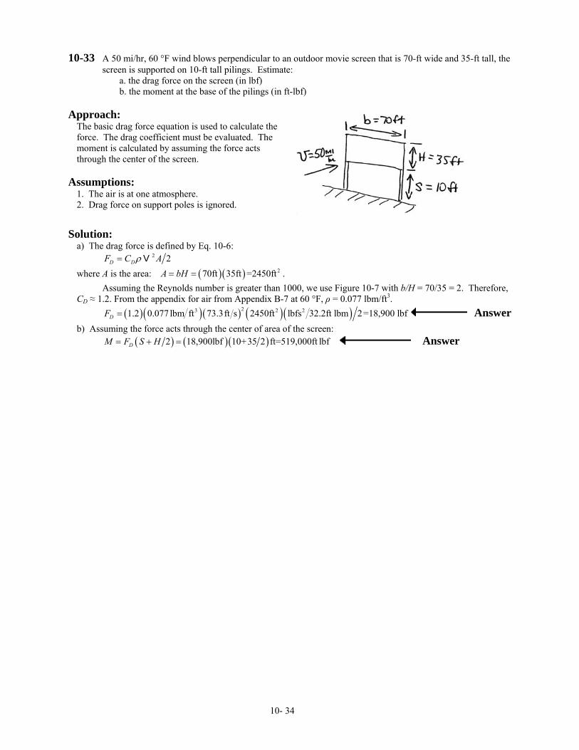
10-33 A 50 mi/hr, 60 °F wind blows perpendicular to an outdoor movie screen that is 70-ft wide and 35-ft tall, the screen is supported on 10-ft tall pilings. Estimate:
a. the drag force on the screen (in lbf) b. the moment at the base of the pilings (in ft-lbf)
Approach:
The basic drag force equation is used to calculate the force. The drag coefficient must be evaluated. The moment is calculated by assuming the force acts through the center of the screen.
Assumptions:
1. The air is at one atmosphere. 2. Drag force on support poles is ignored.
Solution:
a) The drag force is defined by Eq. 10-6: 2 2D DF C Aρ= V where A is the area: . ( )( ) 270ft 35ft =2450ftA bH= = Assuming the Reynolds number is greater than 1000, we use Figure 10-7 with b/H = 70/35 = 2. Therefore, CD ≈ 1.2. From the appendix for air from Appendix B-7 at 60 °F, ρ = 0.077 lbm/ft3. ( )( )( ) ( )( )23 2 21.2 0.077 lbm ft 73.3ft s 2450ft lbfs 32.2ft lbm 2=18,900 lbfDF = Answer b) Assuming the force acts through the center of area of the screen: ( ) ( )( )2 18,900lbf 10+35 2 ft=519,000ft lbfDM F S H= + = Answer
10- 34
10-34 A hotdog company decides to create a giant helium-filled balloon of a hotdog to float in parades for advertising purposes. It will float 75 ft above the street and will be controlled by people holding onto tethering lines. The balloon is 50-ft long and 10-ft in diameter and can be approximated as a cylinder. Air at 70 ºF, 14.7 psia is funneled down the street between the buildings at a velocity of 15 mi/hr. Determine the drag force (in lbf).
Approach:
The drag force with a uniform approach velocity is calculated with the basic equation.
Assumptions:
1. The balloon can be treated as a short cylinder. 2. Air is an ideal gas.
Solution:
The drag force is 2 2D DF C Aρ= V . For air at one atmosphere and 70 ºF, ρ = 0.0749 lbm/ft3. From Table 10-2 for a short cylinder with its axis parallel to the flow and D/L = 50/10 = 5, CD ≈ 0.85
( ) ( ) ( )2 2 2
2 23
lbm mi 5280ft hr π0.85 0.0749 25 10ft lbfs 32.2ft lbm 2hr mi 3600s 4ftDF ⎛ ⎞⎛ ⎞ ⎛ ⎞ ⎛ ⎞= ⎜ ⎟⎜ ⎟ ⎜ ⎟ ⎜ ⎟
⎝ ⎠⎝ ⎠ ⎝ ⎠ ⎝ ⎠
=209lbf Answer
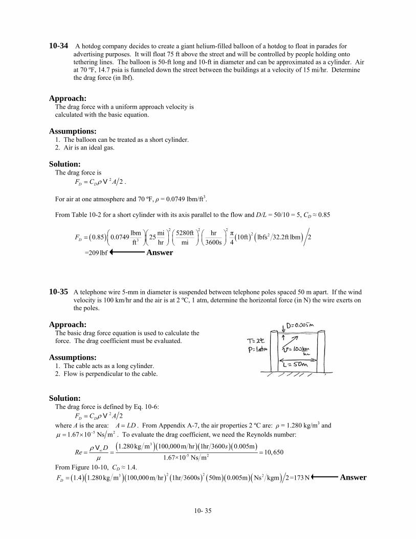
10-35 A telephone wire 5-mm in diameter is suspended between telephone poles spaced 50 m apart. If the wind
velocity is 100 km/hr and the air is at 2 ºC, 1 atm, determine the horizontal force (in N) the wire exerts on the poles.
Approach:
The basic drag force equation is used to calculate the force. The drag coefficient must be evaluated.
Assumptions:
1. The cable acts as a long cylinder. 2. Flow is perpendicular to the cable.
Solution:
The drag force is defined by Eq. 10-6: 2 2D DF C Aρ= V where A is the area: A LD= . From Appendix A-7, the air properties 2 ºC are: ρ = 1.280 kg/m3 and
51.67 10 Ns mµ −= × 2 . To evaluate the drag coefficient, we need the Reynolds number:
( )( )( )( )3
-5 2
1.280kg m 100,000m hr 1hr 3600 0.005m10,650
1.67×10 Ns m
sDRe
ρµ∞= = =
V
From Figure 10-10, CD ≈ 1.4. ( )( )( ) ( ) ( )( )( )2 23 21.4 1.280 kg m 100,000m hr 1hr 3600s 50m 0.005m Ns kgm 2=173NDF = Answer
10- 35
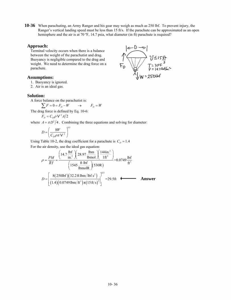
10-36 When parachuting, an Army Ranger and his gear may weigh as much as 250 lbf. To prevent injury, the Ranger’s vertical landing speed must be less than 15 ft/s. If the parachute can be approximated as an open hemisphere and the air is at 70 ºF, 14.7 psia, what diameter (in ft) parachute is required?
Approach:
Terminal velocity occurs when there is a balance between the weight of the parachutist and drag. Buoyancy is negligible compared to the drag and weight. We need to determine the drag force on a parachute.
Assumptions:
1. Buoyancy is ignored. 2. Air is an ideal gas.
Solution:
A force balance on the parachutist is: 0 D DF F W F W= = − → =∑ The drag force is defined by Eq. 10-6: 2 2D DF C Aρ= V where 2 4A Dπ= . Combining the three equations and solving for diameter:
0.5
2
8
D
WDC ρπ
⎛ ⎞= ⎜ ⎟⎝ ⎠V
Using Table 10-2, the drag coefficient for a parachute is 1.4DC = For the air density, use the ideal gas equation:
( )
2
2 2
3
lbf lbm 144in.14.7 28.97lbmolin. 1ft lbf=0.0749
ft lbf ft1545 530RlbmolR
PMRT
ρ
⎛ ⎞⎛ ⎞⎛ ⎞⎜ ⎟⎜ ⎟⎜ ⎟
⎝ ⎠⎝ ⎠⎝ ⎠= =⎛ ⎞⎜ ⎟⎝ ⎠
( )( )
( )( ) ( )
0.52
23
8 250lbf 32.2ft lbm lbf s=29.5ft
1.4 0.0749lbm ft π 15ft sD
⎡ ⎤⎢ ⎥=⎢ ⎥⎣ ⎦
Answer
10- 36
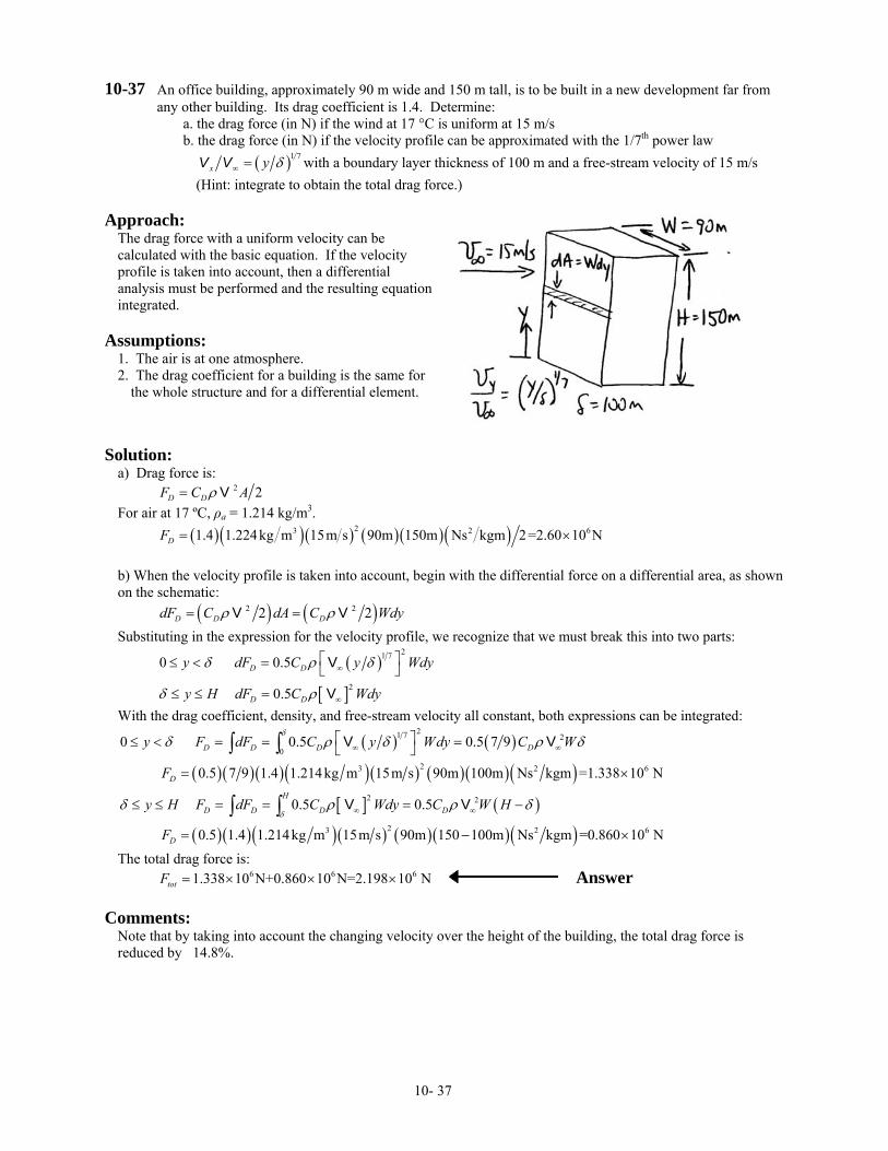
10-37 An office building, approximately 90 m wide and 150 m tall, is to be built in a new development far from any other building. Its drag coefficient is 1.4. Determine:
a. the drag force (in N) if the wind at 17 °C is uniform at 15 m/s b. the drag force (in N) if the velocity profile can be approximated with the 1/7th power law
( )1 7x y δ∞ =V V with a boundary layer thickness of 100 m and a free-stream velocity of 15 m/s
(Hint: integrate to obtain the total drag force.) Approach:
The drag force with a uniform velocity can be calculated with the basic equation. If the velocity profile is taken into account, then a differential analysis must be performed and the resulting equation integrated.
Assumptions:
1. The air is at one atmosphere. 2. The drag coefficient for a building is the same for
the whole structure and for a differential element.
Solution:
a) Drag force is: 2 2D DF C Aρ= V For air at 17 ºC, ρa = 1.214 kg/m3. ( )( )( ) ( )( )( )23 21.4 1.224kg m 15m s 90m 150m Ns kgm 2=2.60 10 NDF = × 6 b) When the velocity profile is taken into account, begin with the differential force on a differential area, as shown on the schematic: ( ) ( )2 22 2D D DdF C dA C Wdyρ ρ= =V V Substituting in the expression for the velocity profile, we recognize that we must break this into two parts:
( )
[ ]
21 7
2
0 0.5
0.5
D D
D D
y dF C y W
y H dF C Wdy
δ ρ δ
δ ρ
∞
∞
⎡ ⎤≤ < = ⎣ ⎦
≤ ≤ =
V
V
dy
With the drag coefficient, density, and free-stream velocity all constant, both expressions can be integrated:
( ) ( )
( )( )( )( )( ) ( )( )( )[ ] ( )
( )( )( )( ) ( )( )( )
21 7 2
0
23 2
2 2
23 2
0 0.5 0.5 7 9
0.5 7 9 1.4 1.214kg m 15m s 90m 100m Ns kgm =1.338 106
6
N
0.5 0.5
0.5 1.4 1.214kg m 15m s 90m 150 100m Ns kgm =0.860 10 N
D D D D
D
H
D D D D
D
y F dF C y Wdy C W
F
y H F dF C Wdy C W H
F
δ
δ
δ ρ δ ρ δ
δ ρ ρ δ
∞ ∞
∞ ∞
⎡ ⎤≤ < = = =⎣ ⎦
= ×
≤ ≤ = = = −
= −
∫ ∫
∫ ∫
V V
V V
×
1.338 10 N+0.860 10 N=2.198 10 NtotF = × × ×
The total drag force is: 6 6 6 Answer
Comments: Note that by taking into account the changing velocity over the height of the building, the total drag force is reduced by 14.8%.
10- 37
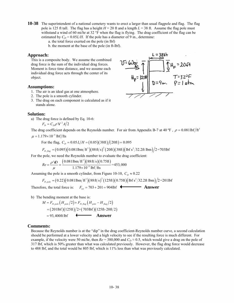
10-38 The superintendent of a national cemetery wants to erect a larger than usual flagpole and flag. The flag pole is 125 ft tall. The flag has a height H = 20 ft and a length L = 38 ft. Assume the flag pole must withstand a wind of 60 mi/hr at 32 °F when the flag is flying. The drag coefficient of the flag can be estimated by CD = 0.05L/H. If the pole has a diameter of 9 in., determine:
a. the total force exerted on the pole (in lbf) b. the moment at the base of the pole (in ft-lbf).
Approach:
This is a composite body. We assume the combined drag force is the sum of the individual drag forces. Moment is force time distance, and we assume each individual drag force acts through the center of its object.
Assumptions:
1. The air is an ideal gas at one atmosphere. 2. The pole is a smooth cylinder. 3. The drag on each component is calculated as if it stands alone.
Solution:
a) The drag force is defined by Eq. 10-6: 2 2D DF C Aρ= V The drag coefficient depends on the Reynolds number. For air from Appendix B-7 at 40 ºF , 30.081lbf ftρ =
51.179 10 lbf ftsµ −= × For the flag, ( )( ) ( )0.05 0.05 38ft 20ft 0.095DC L H= = =
( )( )( ) ( )( )( )23 2, 0.095 0.081lbm ft 88ft s 20ft 38ft lbf s 32.2ft lbm 2=703lbfD flagF =
For the pole, we need the Reynolds number to evaluate the drag coefficient:
( )( )( )3
5
0.081lbm ft 88ft s 0.75ft=453,000
1.179 10 lbf ftsDRe ρµ −= =
×V
Assuming the pole is a smooth cylinder, from Figure 10-10, 0.22DC ≈
( )( )( ) ( )( )( )23 2, 0.22 0.081lbm ft 88ft s 125ft 0.75ft lbf s 32.2ft lbm 2=201lbfD poleF =
Therefore, the total force is: 703 201 904lbftotF = + = Answer b) The bending moment at the base is:
( ) ( )
( ) ( ) ( )( ), ,2 2
201lbf 125ft 2+ 703lbf 125ft-20ft 2D pole pole D flag pole flagM F H F H H= + −
=
93,400ft lbf= Answer
Comments: Because the Reynolds number is at the “dip” in the drag coefficient-Reynolds number curve, a second calculation should be performed at a lower velocity and a high velocity to see if the resulting force is much different. For example, if the velocity were 50 mi/hr, then Re = 380,000 and CD ≈ 0.5, which would give a drag on the pole of 317 lbf, which is 50% greater than what was calculated previously. However, the flag drag force would decrease to 488 lbf, and the total would be 805 lbf, which is 11% less than what was previously calculated.
10- 38
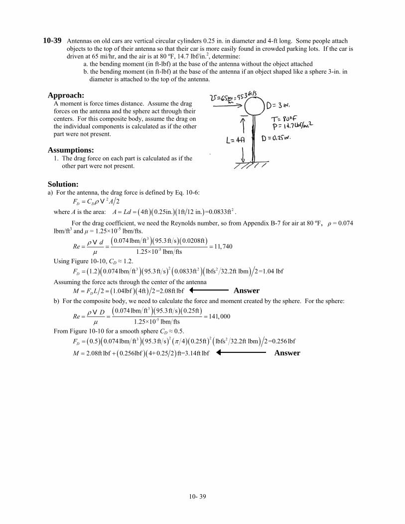
10-39 Antennas on old cars are vertical circular cylinders 0.25 in. in diameter and 4-ft long. Some people attach objects to the top of their antenna so that their car is more easily found in crowded parking lots. If the car is driven at 65 mi/hr, and the air is at 80 ºF, 14.7 lbf/in.2, determine:
a. the bending moment (in ft-lbf) at the base of the antenna without the object attached b. the bending moment (in ft-lbf) at the base of the antenna if an object shaped like a sphere 3-in. in
diameter is attached to the top of the antenna. Approach:
A moment is force times distance. Assume the drag forces on the antenna and the sphere act through their centers. For this composite body, assume the drag on the individual components is calculated as if the other part were not present.
Assumptions:
1. The drag force on each part is calculated as if the other part were not present.
Solution: a) For the antenna, the drag force is defined by Eq. 10-6:
2 2D DF C Aρ= V where A is the area: ( )( )( ) 24ft 0.25in. 1ft 12 in. =0.0833ftA Ld= = .
For the drag coefficient, we need the Reynolds number, so from Appendix B-7 for air at 80 ºF, ρ = 0.074 lbm/ft3 and µ = 1.25×10⁻⁵ lbm/fts.
( )( ) ( )3
-5
0.074lbm ft 95.3ft s 0.0208ft11,740
1.25×10 lbm ftsdRe ρ
µ= = =
V
Using Figure 10-10, CD ≈ 1.2. ( )( )( ) ( )( )23 2 21.2 0.074lbm ft 95.3ft s 0.0833ft lbfs 32.2ft lbm 2=1.04 lbfDF = Assuming the force acts through the center of the antenna ( )( )2 1.04lbf 4ft 2=2.08ft lbfDM F L= = Answer b) For the composite body, we need to calculate the force and moment created by the sphere. For the sphere:
( )( )( )3
-5
0.074lbm ft 95.3ft s 0.25ft141,000
1.25×10 lbm ftsDRe ρ
µ= = =
V
From Figure 10-10 for a smooth sphere CD ≈ 0.5. ( )( )( ) ( ) ( ) ( )2 23 20.5 0.074lbm ft 95.3ft s 4 0.25ft lbfs 32.2ft lbm 2=0.256lbfDF π=
( )( )2.08ft lbf 0.256lbf 4+ 0.25 2 ft=3.14ft lbfM = + Answer
10- 39
10-40 The external rearview mirrors (two each) on old cars were circular disks 10-cm in diameter. New cars use streamlined rearview mirrors (two each) to reduce drag losses; these mirrors can be approximated as hemispheres facing upstream. A car without mirrors has a drag coefficient of 0.36, a frontal area of 1.5 m2, and rolling resistance can be ignored. For a car speed of 125 km/hr in air at 23 ºC, 100 kPa, what percent increase in gas mileage could be obtained by replacing the old mirrors with two new ones of the same diameter?
Approach:
The car plus mirror combination is a composite body. For this composite body, the individual force/power contributions from the car and the mirrors need to be calculated. The total power with and without the mirrors then can be compared. Power is force times velocity
Assumptions:
1. The drag on a composite body can be calculated as if the separate parts act independently. 2. Gas mileage is inversely proportional to power.
Solution:
The drag force is defined by Eq. 10-6: 2 2D DF C Aρ ∞= V For composite bodies, we assume that the drag force contribution from each part is simply additive. Power is: 3 2D DW F C Aρ∞ ∞= =V V For a composite body, we add the contributions from the parts. With velocity, air conditions, and engine efficiency the same for the two mirror types on the car (two mirrors on the car) Therefore, the ratio of power with new and old mirrors is:
( )( )
( )( )
3, , , ,
3, , , ,
2 2 2
2 2 2D car car D mirror mirror D car car D mirror mirrornew new new
old D car car D mirror mirror D car car D mirror mirrorold old
C A C A C A C AWW C A C A C A C A
ρ
ρ∞
∞
+ += =
+ +
V
V
From Table 10-2 For a disk, and , , 1.1D mirror oldC ≈ 2 4A Dπ=
For a hemisphere facing into the velocity, , , 0.4D mirror newC ≈ and 2 4A Dπ= Therefore,
( )( ) ( )( ) ( )( ) ( ) ( )( )( )
22
22
0.36 1.5m +2 0.4 π 4 0.1m0.980
0.36 1.5m +2 1.1 π 4 0.1mnew
old
WW
= =
Therefore, the new mirrors reduce the fuel consumption by about 2.0%. Answer
Comments: By itself the changing of the mirror configuration does not affect the gas mileage dramatically. But many small changes in the aerodynamics of a car plus decreasing the car weight can significantly increase the gas mileage.
10- 40
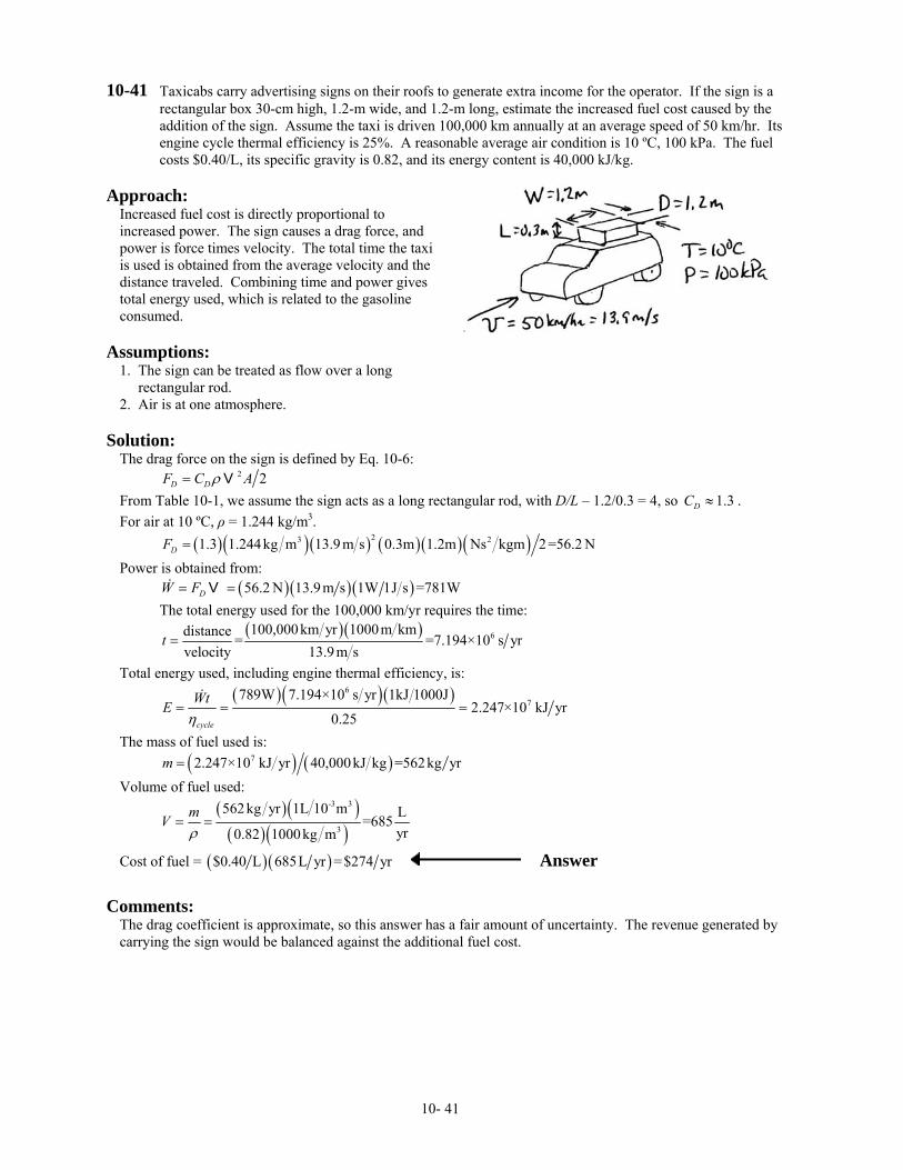
10-41 Taxicabs carry advertising signs on their roofs to generate extra income for the operator. If the sign is a rectangular box 30-cm high, 1.2-m wide, and 1.2-m long, estimate the increased fuel cost caused by the addition of the sign. Assume the taxi is driven 100,000 km annually at an average speed of 50 km/hr. Its engine cycle thermal efficiency is 25%. A reasonable average air condition is 10 ºC, 100 kPa. The fuel costs $0.40/L, its specific gravity is 0.82, and its energy content is 40,000 kJ/kg.
Approach:
Increased fuel cost is directly proportional to increased power. The sign causes a drag force, and power is force times velocity. The total time the taxi is used is obtained from the average velocity and the distance traveled. Combining time and power gives total energy used, which is related to the gasoline consumed.
Assumptions:
1. The sign can be treated as flow over a long rectangular rod. 2. Air is at one atmosphere.
Solution:
The drag force on the sign is defined by Eq. 10-6: 2 2D DF C Aρ= V From Table 10-1, we assume the sign acts as a long rectangular rod, with D/L – 1.2/0.3 = 4, so . 1.3DC ≈For air at 10 ºC, ρ = 1.244 kg/m3. ( )( )( ) ( )( )( )23 21.3 1.244kg m 13.9 m s 0.3m 1.2m Ns kgm 2=56.2 NDF = Power is obtained from: ( )( )( )56.2 N 13.9m s 1W 1J s =781WDW F= =V The total energy used for the 100,000 km/yr requires the time:
( )( ) 6100,000km yr 1000m kmdistance = =7.194×10 s yr
velocity 13.9 m st =
Total energy used, including engine thermal efficiency, is:
( )( )( )6
7789W 7.194×10 s yr 1kJ 1000J
2.247×10 kJ yr0.25cycle
WtEη
= = =
The mass of fuel used is: ( ) ( )72.247×10 kJ yr 40,000kJ kg =562kg yrm = Volume of fuel used:
( )( )( )( )
-3 3
3
562kg yr 1L 10 m L=685yr0.82 1000kg m
mVρ
= =
Cost of fuel = ( ) ( )$0.40 L 685L yr =$274 yr Answer
Comments:
The drag coefficient is approximate, so this answer has a fair amount of uncertainty. The revenue generated by carrying the sign would be balanced against the additional fuel cost.
10- 41
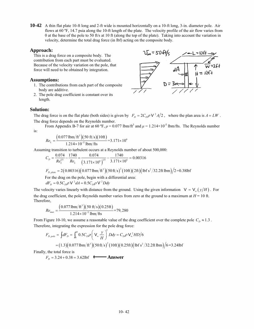
10-42 A thin flat plate 10-ft long and 2-ft wide is mounted horizontally on a 10-ft long, 3-in. diameter pole. Air flows at 60 ºF, 14.7 psia along the 10-ft length of the plate. The velocity profile of the air flow varies from 0 at the base of the pole to 50 ft/s at 10 ft (along the top of the plate). Taking into account the variation in velocity, determine the total drag force (in lbf) acting on the composite body.
Approach:
This is a drag force on a composite body. The contribution from each part must be evaluated. Because of the velocity variation on the pole, that force will need to be obtained by integration.
Assumptions:
1. The contributions from each part of the composite body are additive. 2. The pole drag coefficient is constant over its length.
Solution:
The drag force is on the flat plate (both sides) is given by 22D D 2F C Aρ= V , where the plan area is A LW= . The drag force depends on the Reynolds number. From Appendix B-7 for air at 60 ºF, ρ = 0.077 lbm/ft3 and µ = 1.214×10⁻⁵ lbm/fts. The Reynolds number is:
( )( )( )3
65
0.077 lbm ft 50 ft s 10ft=3.171 10
1.214 10 lbm ftsLRe −= ××
Assuming transition to turbulent occurs at a Reynolds number of about 500,000:
( )1 5 1 5 66
0.074 1740 0.074 1740 0.003163.171 103.171 10
DLL
CReRe
= − = − =××
( )( )( ) ( )( ) ( )23 2, 2 0.00316 0.077 lbm ft 50ft s 10ft 2ft lbf s 32.2ft lbm 2=0.38lbfD plateF =
For the drag on the pole, begin with a differential area: 2 20.5 0.5D D DdF C dA C Ddyρ ρ= =V VThe velocity varies linearly with distance from the ground. Using the given information ( )y H∞=V V . For the drag coefficient, the pole Reynolds number varies from zero at the ground to a maximum at H = 10 ft. Therefore,
( )( )( )3
5
0.077 lbm ft 50 ft s 0.25ft=79,280
1.214 10 lbm ftsmaxRe −=×
From Figure 10-10, we assume a reasonable value of the drag coefficient over the complete pole . Therefore, integrating the expression for the pole drag force:
1.3DC ≈
( )( )( ) ( )( ) ( )
22
, 0
23 2
0.5 6
1.3 0.077 lbm ft 50ft s 10ft 0.25ft lbf s 32.2ft lbm 6 =3.24lbf
H
D pole D D DyF dF C Ddy C HDH
ρ ρ∞ ∞⎛ ⎞= = =⎜ ⎟⎝ ⎠
=
∫ ∫ V V
Finally, the total force is 3.24 0.38 3.62lbfDF = + = Answer
10- 42
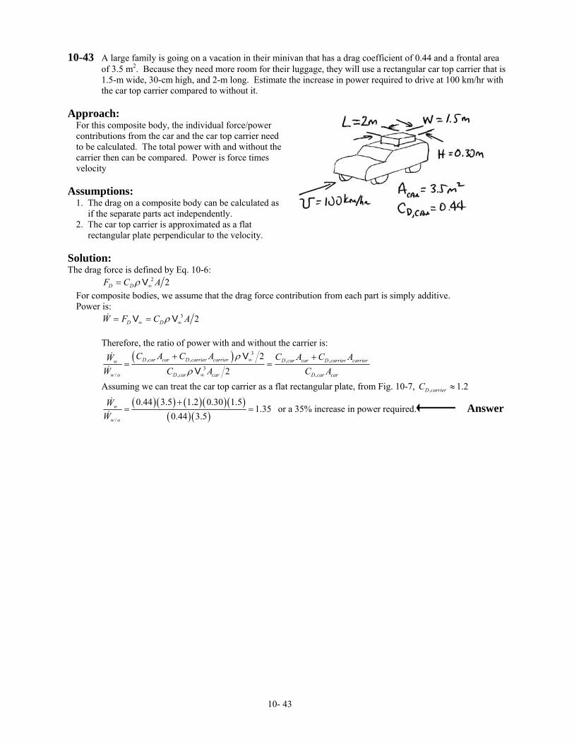
10-43 A large family is going on a vacation in their minivan that has a drag coefficient of 0.44 and a frontal area of 3.5 m2. Because they need more room for their luggage, they will use a rectangular car top carrier that is 1.5-m wide, 30-cm high, and 2-m long. Estimate the increase in power required to drive at 100 km/hr with the car top carrier compared to without it.
Approach:
For this composite body, the individual force/power contributions from the car and the car top carrier need to be calculated. The total power with and without the carrier then can be compared. Power is force times velocity
Assumptions:
1. The drag on a composite body can be calculated as if the separate parts act independently. 2. The car top carrier is approximated as a flat rectangular plate perpendicular to the velocity.
Solution: The drag force is defined by Eq. 10-6:
2 2D DF C Aρ ∞= V For composite bodies, we assume that the drag force contribution from each part is simply additive. Power is: 3 2D DW F C Aρ∞ ∞= =V V Therefore, the ratio of power with and without the carrier is:
( ) 3
, , , ,3
,/ ,
22
D car car D carrier carrier D car car D carrier carrierw
D car carw o D car car
C A C A C A C AWC AW C A
ρρ
∞
∞
+ += =
VV
Assuming we can treat the car top carrier as a flat rectangular plate, from Fig. 10-7, , 1.2D carrierC ≈
( )( ) ( )( )( )
( ) ( )/
0.44 3.5 1.2 0.30 1.51.35
0.44 3.5w
w o
WW
+= = or a 35% increase in power required. Answer
10- 43

10-44 A small aircraft has a wing area of 27 m2, a take-off mass of 2500 kg, a lift coefficient at take-off of 0.49, and a drag coefficient at take-off of 0.0074. For standard atmospheric conditions, determine:
a. the take-off speed at sea level (in km/hr) b. the power required at take-off (in kW) c. the maximum mass (in kg) possible at take-off speed using the power from part (b) if the airport is at
2500 m. Approach:
The take-off speed is obtained by knowing that lift force equals weight at take-off. The basic equations are used, and a standard atmosphere is assumed.
Assumptions:
1. The air conditions equal the standard atmosphere.
Solution:
a) At take-off speed, lift force equals weight: LF W mg= = The lift force is calculated with 2 2L LF C Aρ= V . Combining these two expressions and solving for velocity:
0.5
2
L
mgC Aρ
⎛ ⎞= ⎜ ⎟⎝ ⎠
V
From Table 10-5, 31.225kg mρ =
( ) ( )
( )( )( )
0.52
3 2
2 2500kg 9.81m s m kmr
=55.0 198s h0.49 1.225kg m 27m
⎡ ⎤⎢ ⎥= =⎢ ⎥⎣ ⎦
V Answer
b) Power is obtained from: 2 2D DW F C Aρ= =V V . Note that 2 2D DF C Aρ= V . Dividing the drag force by the lift force: D L D LF F C C= . Therefore,
( )D LW C C mg= V
( )( )( )( )( )( )2 20.0074 0.49 2500kg 9.81m s 55.0m s 1Ns kgm 1Ws Nm =20,370W= Answer c) At higher elevation, we have two equations: 2 2L LF W C Aρ= → =V mg 3 2D DF W C Aρ= → =V V W From the second equation, we can obtain the maximum velocity at the higher elevation using the power from part (b). Solving for velocity:
1 3
2
D
WC Aρ
⎛ ⎞= ⎜ ⎟⎝ ⎠
V
From Table 10-5 by interpolation, ( )( )3 30.782 1.225kg m 0.958kg mρ ≈ =
( )( )( )( )( )( )
1 32
3 2
2 20370W Nm Ws kgm Ns m k=59.7 215s h0.0074 0.958kg m 27m
⎡ ⎤⎢ ⎥= =⎢ ⎥⎣ ⎦
V mr
From the first equation:
( )( )( ) ( )
( )
23 22
2
0.49 0.958kg m 59.7 m s 27m=2300kg
2 2 9.81m sLC Am
gρ
= =V Answer
10- 44
10-45 For a small plane, the lift coefficient at the landing speed is 1.15, and the maximum lift coefficient (at the stall speed) is 1.42. The landing speed of the airplane is 8 m/s faster than its stall speed. Determine both the landing and stalling speeds (in m/s).
Approach:
At landing and stall, the lift force just equals the weight of the plane. We can use the given information and the basic definitions of lift force to determine the two speeds.
Assumptions:
1. The air is an ideal gas. 2. The pole is a smooth cylinder.
Solution:
Let V L = the speed at landing and V S = the speed at stall. These two speeds are related by 8m sL S= +V V At landing and at stall, lift force equals weight: Landing: 2
, 2L L L LF C Aρ= =V mg
Stall: 2, 2L L S SF C Aρ= =V mg
Equating the two equations and simplifying: 2 2
, ,L S S L L LC C=V V Substituting in the relationship between stall and landing speed: ( )22
, , 8m sL S S L L SC C= +V V
( ) ( )( )221.42 1.15 8m sS S= +V V Solving for the velocities: 71.9m sS =V Answer 71.9+8=79.8m sL =V Answer
10- 45
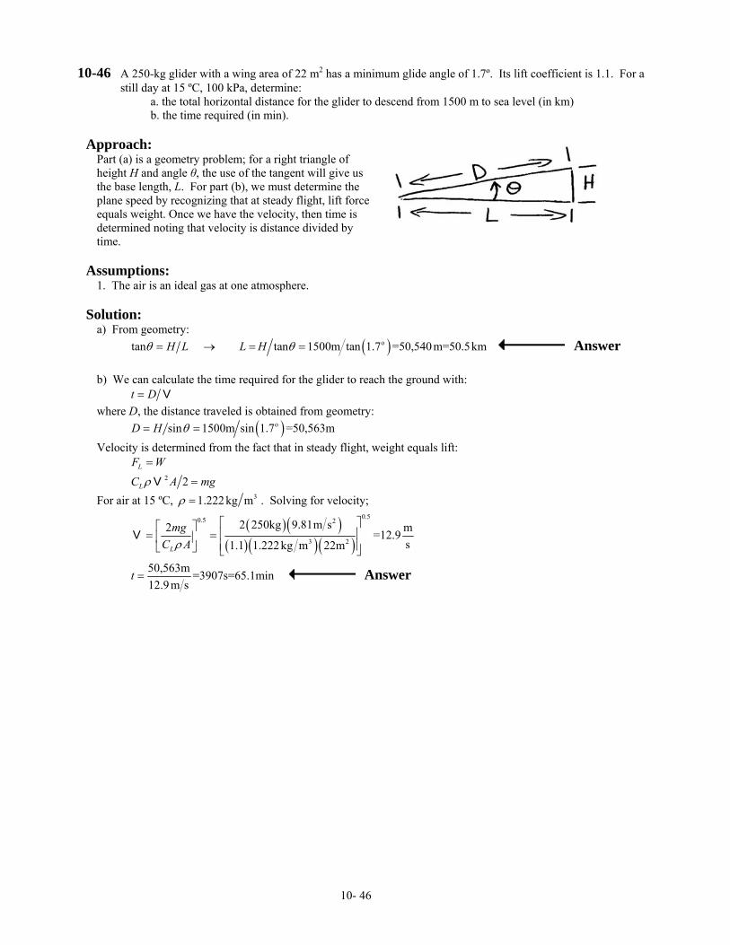
10-46 A 250-kg glider with a wing area of 22 m2 has a minimum glide angle of 1.7º. Its lift coefficient is 1.1. For a still day at 15 ºC, 100 kPa, determine:
a. the total horizontal distance for the glider to descend from 1500 m to sea level (in km) b. the time required (in min).
Approach:
Part (a) is a geometry problem; for a right triangle of height H and angle θ, the use of the tangent will give us the base length, L. For part (b), we must determine the plane speed by recognizing that at steady flight, lift force equals weight. Once we have the velocity, then time is determined noting that velocity is distance divided by time.
Assumptions:
1. The air is an ideal gas at one atmosphere.
Solution:
a) From geometry: ( )otan tan 1500m tan 1.7 =50,540m=50.5kmH L L Hθ θ= → = = Answer b) We can calculate the time required for the glider to reach the ground with: t D= V where D, the distance traveled is obtained from geometry: ( )osin 1500m sin 1.7 =50,563mD H θ= = Velocity is determined from the fact that in steady flight, weight equals lift:
2 2L
L
F WC A mρ
=
=V g
For air at 15 ºC, 31.222kg mρ = . Solving for velocity;
( )( )
( )( ) ( )
0.50.5 2
3 2
2 250kg 9.81m s2 m=12.9s1.1 1.222kg m 22mL
mgC Aρ
⎡ ⎤⎡ ⎤⎢ ⎥= =⎢ ⎥⎢ ⎥⎣ ⎦ ⎣ ⎦
V
50,563m =3907s=65.1min12.9m s
t = Answer
10- 46
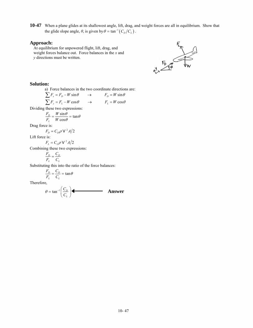
10-47 When a plane glides at its shallowest angle, lift, drag, and weight forces are all in equilibrium. Show that the glide slope angle, θ, is given by ( )1tan D LC Cθ −= .
Approach:
At equilibrium for unpowered flight, lift, drag, and weight forces balance out. Force balances in the x and y directions must be written.
Solution: a) Force balances in the two coordinate directions are:
sin sin
cos cosx D D
y L L
F F W F W
F F W F W
θ θ
θ θ
= − → =
= − → =∑∑
Dividing these two expressions:
sin tancos
D
L
F WF W
θ θθ
= =
Drag force is: 2 2D DF C Aρ= V Lift force is: 2 2L LF C Aρ= V Combining these two expressions:
D D
L L
F CF C
=
Substituting this into the ratio of the force balances:
tanD D
L L
F CF C
θ= =
Therefore,
1tan D
L
CC
θ − ⎛ ⎞= ⎜ ⎟
⎝ ⎠ Answer
10- 47
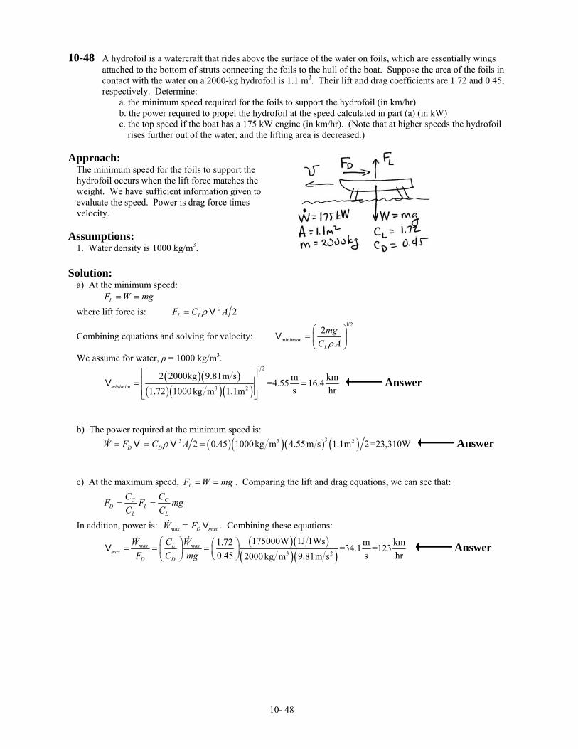
10-48 A hydrofoil is a watercraft that rides above the surface of the water on foils, which are essentially wings attached to the bottom of struts connecting the foils to the hull of the boat. Suppose the area of the foils in contact with the water on a 2000-kg hydrofoil is 1.1 m2. Their lift and drag coefficients are 1.72 and 0.45, respectively. Determine:
a. the minimum speed required for the foils to support the hydrofoil (in km/hr) b. the power required to propel the hydrofoil at the speed calculated in part (a) (in kW) c. the top speed if the boat has a 175 kW engine (in km/hr). (Note that at higher speeds the hydrofoil
rises further out of the water, and the lifting area is decreased.) Approach:
The minimum speed for the foils to support the hydrofoil occurs when the lift force matches the weight. We have sufficient information given to evaluate the speed. Power is drag force times velocity.
Assumptions:
1. Water density is 1000 kg/m3. Solution:
a) At the minimum speed: LF W mg= = where lift force is: 2 2L LF C Aρ= V
Combining equations and solving for velocity: 1 2
2minimum
L
mgC Aρ
⎛ ⎞= ⎜ ⎟⎝ ⎠
V
We assume for water, ρ = 1000 kg/m3.
( )( )
( )( )( )
1 2
3 2
2 2000kg 9.81m s m kmr
=4.55 16.4s h1.72 1000 kg m 1.1mminimim
⎡ ⎤⎢ ⎥= =⎢ ⎥⎣ ⎦
V Answer
b) The power required at the minimum speed is: ( )( )( ) ( )33 3 22 0.45 1000kg m 4.55m s 1.1m 2=23,310WD DW F C Aρ= = =V V Answer c) At the maximum speed, LF W mg= = . Comparing the lift and drag equations, we can see that:
C CD L
L L
C CF F mC C
= = g
In addition, power is: . Combining these equations: max D maxW = F V
( )( )
( )( )3 2
175000W 1J 1Ws1.72 m km=34.1 =1230.45 s hr2000kg m 9.81m s
max maxLmax
D D
W WCF C mg
⎛ ⎞ ⎛ ⎞= = =⎜ ⎟ ⎜ ⎟⎝ ⎠⎝ ⎠
V Answer
10- 48
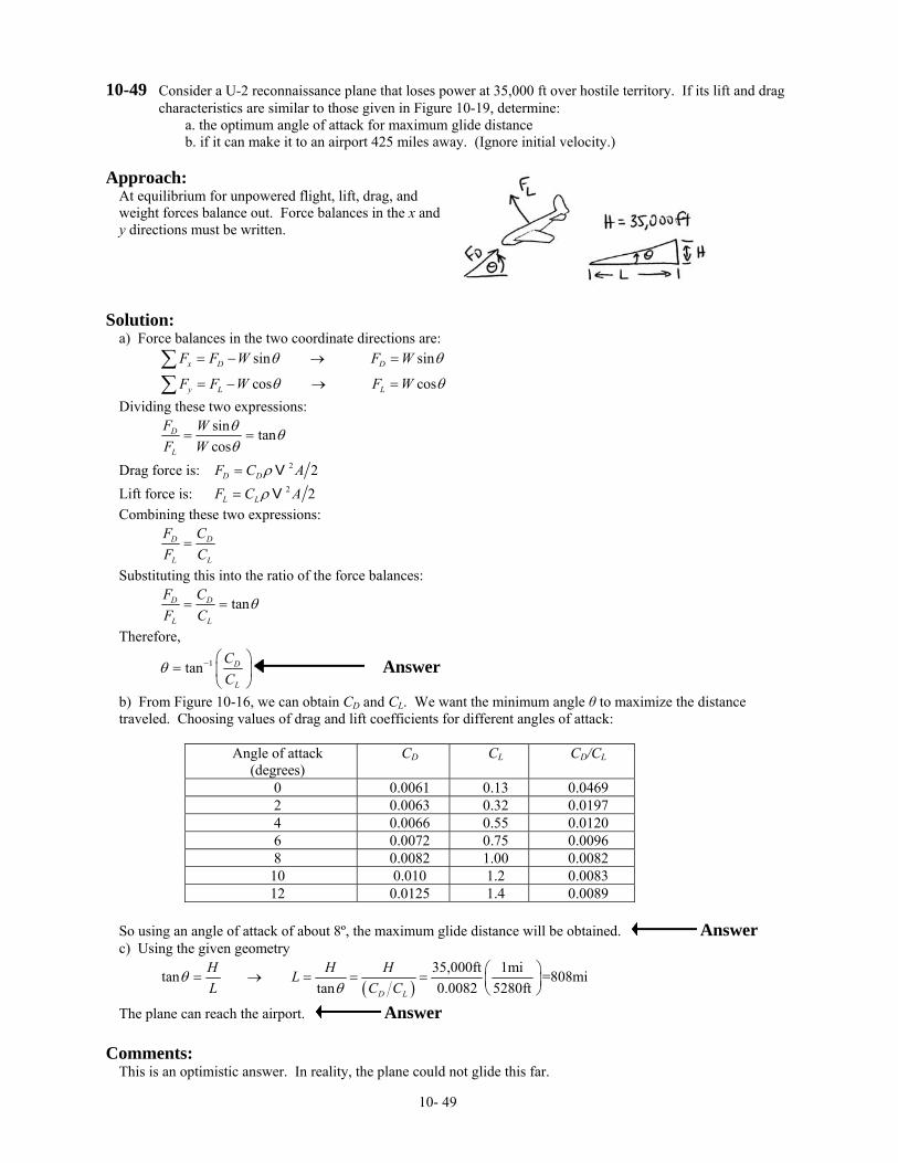
10-49 Consider a U-2 reconnaissance plane that loses power at 35,000 ft over hostile territory. If its lift and drag characteristics are similar to those given in Figure 10-19, determine:
a. the optimum angle of attack for maximum glide distance b. if it can make it to an airport 425 miles away. (Ignore initial velocity.)
Approach:
At equilibrium for unpowered flight, lift, drag, and weight forces balance out. Force balances in the x and y directions must be written.
Solution:
a) Force balances in the two coordinate directions are:
sin sin
cos cosx D D
y L L
F F W F W
F F W F W
θ θ
θ θ
= − → =
= − → =∑∑
Dividing these two expressions:
sin tancos
D
L
F WF W
θ θθ
= =
Drag force is: 2 2D DF C Aρ= V Lift force is: 2 2L LF C Aρ= V Combining these two expressions:
D D
L L
F CF C
=
Substituting this into the ratio of the force balances:
tanD D
L L
F CF C
θ= =
Therefore,
1tan D
L
CC
θ − ⎛ ⎞= ⎜ ⎟
⎝ ⎠ Answer
b) From Figure 10-16, we can obtain CD and CL. We want the minimum angle θ to maximize the distance traveled. Choosing values of drag and lift coefficients for different angles of attack:
Angle of attack (degrees)
CD CL CD/CL
0 0.0061 0.13 0.0469 2 0.0063 0.32 0.0197 4 0.0066 0.55 0.0120 6 0.0072 0.75 0.0096 8 0.0082 1.00 0.0082
10 0.010 1.2 0.0083 12 0.0125 1.4 0.0089
So using an angle of attack of about 8º, the maximum glide distance will be obtained. Answer c) Using the given geometry
( )
35,000ft 1mitan =808mitan 0.0082 5280ftD L
H H HLL C C
θθ
⎛ ⎞= → = = = ⎜ ⎟⎝ ⎠
The plane can reach the airport. Answer
Comments: This is an optimistic answer. In reality, the plane could not glide this far.
10- 49

10-50 If you have ever flown a kite in a strong wind, you know that the pull on the string can be quite strong. Consider a 1.2-m by 0.8-m kite that has a mass of 0.5 kg. Its lift coefficient can be approximated by
2 sinLC π α= where α is the angle of attack. In a 45 km/hr wind, the kite’s string has an angle of 50° to the horizontal, and the kite has an angle of attack of 5°. Determine the force on the string (in N).
Approach:
The tension in the string can be obtained from a force balance on the kite.
Assumptions:
1. Air is an ideal gas at one atmosphere.
Solution:
A force balance on the kite in the y-direction is:
0 sinsin sin
L kite Ly L kite
F W F mgF F T W Tθθ θ
− −= = − − → = =∑
The lift force is defined by: 2 2L LF C Aρ= V Assuming air is an ideal gas at 25 ºC, one atmosphere, ρ = 1.181 kg/m3. For the drag coefficient: ( )o2 sin 5 0.548LC π= =
The lift force is: ( )( )( ) ( )( )( )23 20.548 1.181kg m 12.5m s 1.2m 0.8m Ns kgm 2 =48.5NLF = The tension force is:
( )( )( )
( )2 2
o
48.5N- 0.5kg 9.81m s Ns kgm=56.9N
sin 50T = Answer
10-51 A small experimental plane has a mass of 750 kg, a drag coefficient of 0.063, and a lift coefficient of 0.4. In level flight, it is flown at 175 km/hr. For standard conditions (1 atm, 25 ºC), determine the effective lift area of the plane (in m2).
Approach:
The basic equation for lift force is applied directly to this problem. For steady flight, weight equals lift. Sufficient information is given to solve for the plan area.
Assumptions:
1. Air properties are at 25 ºC, 1 atm.
Solution:
The lift force is calculated with the following equation: 2 2L LF C Aρ= V In steady flight, lift equals weight: LF W mg= = Combining the equations and solving for effective area:
2
2
L a
mgAC ρ
=V
For air at 25 ºC, ρ = 1.184 kg/m3.
( )( )( )
( )( )( )
222
23
2 750kg 9.81m s 3600s hr=13.1m
0.4 1.184kg m 175000m hrA = Answer
10- 50
10-52 Because of the decrease in density and temperature with increasing elevation in the atmosphere, lift and drag forces change. Consider a plane flying at velocity at sea level. For the same lift and drag coefficients, determine:
V
a. the speed required at 10,000 m to generate the same lift force b. the change in drag force.
Approach:
At steady flight, lift equals weight. We can compare the velocity requirements at two different elevations using the basic definition of lift force.
Assumptions:
1. The lift coefficient is constant.
Solution:
a) In steady flight, LF W= The lift force is defined by: 2 22 2L L LF C A C Aρ ρ= →V V W= For two different elevations, we can find the relative velocities required by taking a ratio of the equation above evaluated at the two conditions:
2
,1 1 1 1 12
2,2 2 2 2
22
L
L
C A WWC A
ρρ
=VV
Because the weight, area, and lift coefficient are the same at the two conditions:
0.50.52
1 02 1 2 12
2 1 2 21
ρ ρρ ρρ ρ ρ
⎛ ⎞⎛ ⎞= → = = ⎜ ⎟⎜ ⎟
⎝ ⎠ ⎝ ⎠
V VVV 0ρ
Obtaining the values of density at different elevations from Table 10-5:
0.5
2
1
1 1.720.3376
⎛ ⎞= =⎜ ⎟⎝ ⎠
VV
Answer
b) Drag force is 2 2D DF C Aρ= V . Taking the ratio of the forces at the two conditions:
2 2
,2 ,2 2 2 2 2 22 2
,1 ,1 1 1 1 1 1
22
D D
D D
F C AF C A
ρ ρρ ρ
= =V VV V
Using the relation given above for the ratio of velocities
,2 2 1
,1 1 2
1D
D
FF
ρ ρρ ρ
⎛ ⎞⎛ ⎞= =⎜ ⎟⎜ ⎟⎝ ⎠⎝ ⎠
Answer
10- 51
10-53 When planes take-off and land at airports at higher elevations, the lower density air (due to reduced atmospheric pressure) must be taken into account because of its effect on lift and drag. If a plane requires 15 s to reach its take-off speed of 220 km/hr at sea level in a distance of 500m, estimate for an airport at 2000 m:
a. the take-off speed (in km/hr) b. the take-off time (in s) c. the additional runway length required (in m). Assume the same constant acceleration for both cases.
Approach:
The take-off speed is obtained by knowing that lift force equals weight at take-off; the take-off speed at the second elevation can be obtained by comparison. The additional time and distance required at the second elevation can be approximated by a force balance that now takes into account the acceleration. (Use Newton’s second law of motion.)
Assumptions:
1. Lift coefficient is the same at both elevations and speeds.
Solution:
a) At take-off speed, lift force equals weight: LF W mg= = The lift force is calculated with 2 2L LF C Aρ= V . Combining these two expressions and solving for velocity:
0.5
2
L
mgC Aρ
⎛ ⎞= ⎜ ⎟⎝ ⎠
V
Assuming the lift coefficient is the same at both elevations and speeds, the ratio of the speeds is:
0.50.5
1 02 1
1 2 2 0
ρ ρρρ ρ ρ
⎛ ⎞⎛ ⎞= = ⎜ ⎟⎜ ⎟⎝ ⎠ ⎝ ⎠
VV
From Table 10-5, at 2000 m, 2 0 0.8217ρ ρ = → ( ) ( )0.52 220km hr 1 0.8217 243km hr= =V Answer
b) To find the additional time, we need to take into account the acceleration of the plane. Using Newton’s second law of motion: x D xF F ma m d d= − = − = −∑ V t
Drag force is 2 2D DF C Aρ= V . Substituting this into the force balance, separating variables, and integrating from zero (the initial velocity) to the take-off velocity:
2 0 2f
i
t DC Ad dtmρ
=∫ ∫V
V
VV
→ 1 1 12
f
i
D
i f
C A tmρ
− = − =V
VV V V → 2 1 1
D f i
mtC Aρ
⎛ ⎞= − −⎜ ⎟⎜ ⎟
⎝ ⎠V V
If we let the initial velocity go to zero, then its inverse goes to infinity. Therefore, assume the initial velocity is 1 km/hr, and the ratio of times is:
( )( )( )( ) ( )2 22
21 1 1
1 1 1 1 1 243 1 15s =18.3s1 1 1 0.8217 1 220 1
t tt
ρρ
− ⎛ ⎞−⎛ ⎞= → = ⎜ ⎟⎜ ⎟− ⎝ ⎠⎝ ⎠
VV −
Answer
c) For the distance, we revisit the original force balance: 2 2D x D xF ma C A maρ− = − → =V
Note that xa d d= V t , and using the chain rule on the derivative: xd d dx dadt dx dt dx
= = =V V VV
Substituting this expression into the force balance, separating variables, and integrating:
2
0
22 ln2 2
f
i
x f fD DD
i D
C A C Ad dC A m dx x xdx m m C A
ρ ρρ
ρ⎛ ⎞ ⎛ ⎞
= → = → = → =⎜ ⎟ ⎜ ⎟⎝ ⎠ ⎝ ⎠
∫ ∫V
V
V VV VV VV V
lni
mV
Therefore, ( ) ( )( ) ( )
2 22
1 1 1
1 ln1 ln
i
i
xx
ρρ
=V VV V
. Assuming the initial velocity is 1 km/hr:
( ) ( )( ) ( ) ( )
( )2
2 1 1 21
ln ln 2431500m =620mln 0.8217 ln 220
x x ρ ρ ⎛ ⎞= = ⎜ ⎟⎝ ⎠
VV
Answer
10- 52
10-54 An airplane is to be designed that will fly at 650 km/hr at an altitude where the density is 0.655 kg/m3 and the kinematic viscosity is 2 × 10⁻⁵ m2/s. A 1/15th scale model (that is, the model is geometrically similar to the prototype but is 1/15th its size) is built for use in a wind tunnel whose velocity is 650 km/hr. The air in the wind tunnel is at 55 ºC, and viscosity is independent of pressure. Determine:
a. the test section pressure (in kPa) so that the model data are useful in designing the prototype (Hint: match Reynolds numbers)
b. what is the relation between the drag on the prototype and that on the model? Approach:
To match the flow conditions, the Reynolds number of the prototype and model should be equal. For the relationship between the drag of the prototype and the drag of the model, we assume because the Reynolds numbers are the same, the drag coefficients are equal. We then can use the drag coefficient to determine the relationship.
Assumptions:
1. Flow similarity occurs when Reynolds numbers match. 2. Drag coefficient depends only on Reynolds number. 3. Air is an ideal gas.
Solution:
a) For flow similarity, we set the Reynolds numbers equal to each other:
p m
p p p m m m
p m
Re = Re
L Lρ ρµ µ
=V V
The velocities and viscosities are the same, and 1 15m pL L = . Therefore,
( ) ( )( )3 30.655kg m 15 =9.825kg mm p p mL Lρ ρ= = For the pressure, we use the ideal gas law:
( ) ( )3 kJ9.825kg m 8.314 55+273 K
kmolK =925kPakg28.97
kmol
RTPMρ
⎛ ⎞⎜ ⎟⎝ ⎠= =⎛ ⎞⎜ ⎟⎝ ⎠
Answer
b) To find the relationship between the drag forces on the prototype and model, we take the ratio of the drag force expressions:
2
, ,2
, ,
22
D p D p p p p
D m D m m m m
F C AF C A
ρρ
=VV
Canceling like terms and noting that ( ) ( )2 21 15m p m pA A L L= =
( )2
2,
,
0.655 15 159.825
D p p p
D m m m
F LF L
ρρ
⎛ ⎞⎛ ⎞ ⎛ ⎞= = =⎜ ⎟⎜ ⎟ ⎜ ⎟⎝ ⎠⎝ ⎠⎝ ⎠
Answer
10- 53
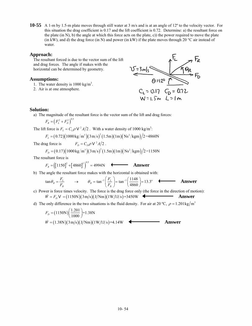
10-55 A 1-m by 1.5-m plate moves through still water at 3 m/s and is at an angle of 12º to the velocity vector. For this situation the drag coefficient is 0.17 and the lift coefficient is 0.72. Determine: a) the resultant force on the plate (in N), b) the angle at which this force acts on the plate, c)) the power required to move the plate (in kW), and d) the drag force (in N) and power (in kW) if the plate moves through 20 °C air instead of water.
Approach:
The resultant forced is due to the vector sum of the lift and drag forces. The angle if makes with the horizontal can be determined by geometry.
Assumptions:
1. The water density is 1000 kg/m3. 2. Air is at one atmosphere.
Solution:
a) The magnitude of the resultant force is the vector sum of the lift and drag forces: ( )0.52 2
R L DF F F= +
The lift force is 2 2L LF C Aρ= V . With a water density of 1000 kg/m3:
( )( )( ) ( )( )( )23 20.72 1000kg m 3m s 1.5m 1m Ns kgm 2=4860NLF =
The drag force is 2 2D DF C Aρ= V .
( )( )( ) ( )( )( )23 20.17 1000kg m 3m s 1.5m 1m Ns kgm 2=1150NDF = The resultant force is
[ ] [ ]( )0.52 21150 4860 4994NRF = + = Answer
b) The angle the resultant force makes with the horizontal is obtained with:
1 1 o1148tan tan tan 13.34860
L LR R
R R
F FF F
θ θ − −⎛ ⎞ ⎛ ⎞= → = = =⎜ ⎟ ⎜ ⎟⎝ ⎠⎝ ⎠
Answer
c) Power is force times velocity. The force is the drag force only (the force in the direction of motion): ( ) ( )( )( )1150N 3m s J Nm 1W 1J s =3450WDW F= =V Answer
d) The only difference in the two situations is the fluid density. For air at 20 ºC, 31.201kg mρ =
( ) 1.2011150N =1.38N1000DF ⎛ ⎞= ⎜ ⎟
⎝ ⎠
( )( )( )( )1.38N 3m s J Nm 1W 1J s =4.14WW = Answer
10- 54
10-56 An expression for the laminar velocity profile on a flat plate is: ( )1 2sinx C C y C= +V 3
where the argument of the sine function is in radians. Using the three common physical conditions that the velocity profile should satisfy, determine:
a. the constants C1, C2, and C3b. the non-dimensional velocity profile c. the boundary thickness ( )xδ as a function of length d. the skin friction coefficient, Cf, as a function of length.
Approach:
The velocity profile is given by ( )1 2sinx C C y C= +V 3
0=
. Using the approach given in the momentum integral example problem, the constants can be evaluated using the boundary conditions listed after Eq. 10-21. The boundary layer thickness and the skin friction coefficient can be evaluated with Eqs. 10-27 and 10-28, respectively.
Assumptions:
1. The momentum integral approach is valid. 2. The assumed profile is reasonable.
Solution:
a) Using the three boundary conditions listed after Eq. 10-21: 1. At y = 0, → 0x =V ( )1 3 30 sin 0C C C= + →
2. At y = δ, → x ∞=V V ( )1 2sinC C δ∞ =V
3. At y = δ, ( ) 0xd dy =V → ( ) ( )1 2 2cos 0xd dy C C C δ= =V
From boundary condition 3, ( )2 2 2cos 0 2 2C C Cδ δ π π δ= → = → =
Substituting this into boundary condition 2, [ ]( ) ( )1 1sin 2 sin 2C Cπ δ δ π∞ 1C= = =V
Therefore, ( )sin sin2 2
xx
y Fπ πη ηδ∞
∞
⎛ ⎞ ⎛= → = =⎜ ⎟ ⎜⎝ ⎠ ⎝
VV V
V⎞⎟⎠
Answer
b) The boundary layer thickness is defined by Eq. 10-27: 2
xx Reβ γδ
= . From Eq. 10-24:
( ) ( )
( )
1 1
0 01
0
1 sin 1 sin2 2
2 1 1 2cos sin 0 1 0 0 0 0.1372 2 2 4 4
F F d dπ πγ η η η η η η
π π πη η πηπ π
⎡ ⎤⎛ ⎞ ⎛ ⎞= − = −⎡ ⎤ ⎜ ⎟ ⎜ ⎟⎢ ⎥⎣ ⎦ ⎝ ⎠ ⎝ ⎠⎣ ⎦
⎡ ⎤⎛ ⎞ ⎡ ⎤= − − + = + − + + − =⎜ ⎟⎢ ⎥ ⎢ ⎥⎝ ⎠ ⎣ ⎦⎣ ⎦
∫ ∫
Using Eq. 10-25: 00 0
sin cos2 2 2
dF dd d ηη η
2π π πβ η
η η == =
⎡ ⎛ ⎞ ⎛ ⎞= = = =⎜ ⎟ ⎜ ⎟⎢ ⎝ ⎠ ⎝ ⎠⎣
πη
Using Eq. 10-27: ( )2 2 0.137 4.80
x xx Re Re
πδ= = Answer
c) The skin friction coefficient is defined by Eq. 10-28 ( )( )2 2 0.1372 0.656
fx x x
CRe Re Re
πβγ= = = Answer
Comments: Note that the boundary layer thickness constant of 4.80 is a good approximation to the Blasius solution of 5.0, as is the skin friction coefficient of 0.656 compared to the Blasius solution of 0.664.
10- 55
10-57 The velocity distribution in a laminar boundary layer on a smooth flat plate is given by ( ) ( )23 2x y yδ δ∞ = −V V . Develop an expression for the drag coefficient.
Approach:
With the given laminar velocity profile 23 2x η η∞ = −V V , where yη δ= , the drag
coefficient can be evaluated with Eq. 10-29. Assumptions:
1. The momentum integral approach is valid. 2. The assumed velocity profile is reasonable.
Solution:
From the momentum integral solution for flow in a boundary layer, the drag coefficient can be evaluated with Eq. 10-29:
2 2
DL
CReβγ
=
The two constants are evaluated with the appropriate equations. From Eq. 10-24:
( ) ( ) ( ) ( )
( )
1 12 2
0 0
12 3 4
0
1 3 2 1 3 2
13 11 12 430
F F d d
d
γ η η η η η η η
η η η η η
η⎡ ⎤= − = − − −⎡ ⎤⎣ ⎦ ⎣ ⎦
= − + − =
∫ ∫
∫
Using Eq. 10-25: ( )20
0 0
3 2 3 4 3dF dd d η
η η
β η η ηη η =
= =
⎡= = − = −⎣ =
Therefore,
( )( )2 2 3 1 30 0.894D
L L
CRe Re
= =
Comments:
This has poor agreement with the Blasius solution, whose constant is 1.328. We can determine why by considering Assumption No. 2 (the velocity profile is reasonable). Three boundary conditions are given in the text that a velocity profile should satisfy. We satisfy the first two boundary conditions. However, we do not satisfy the third boundary condition. Hence, this velocity profile is not reasonable.
10- 56
10-58 Measurements from flow over a flat plate results in the turbulent velocity profile ( )1 9x y δ∞ =V V and skin
friction coefficient 1 50.046fC = xRe . Develop a relationship that describes the growth of the boundary layer thickness. (Note that Eq. 10-8 cannot be used.)
Approach:
We can follow the development used with the momentum integral equation, but we need to bring in the information about the skin friction coefficient.
Assumptions:
1. The momentum integral approach is valid. 2. The assumed velocity profile is reasonable. 3. The measured/correlated Cf is valid.
Solution:
Letting yη δ= , we are given
1 9x η∞ =V V and 1 50.046f xC R= e
Note that the skin friction coefficient is defined as:
20.5w
fCτρ ∞
=V
(1)
From the momentum integral analysis, Eq. 10-23
( ) ( )1
20
1w d F F ddx
τδ η η
ρ ∞
⎡ ⎤= −⎡ ⎤⎢ ⎣ ⎦
⎣ ⎦∫V
η⎥ (2)
Rewriting equation 1 and incorporating the skin friction expression:
2 1 5
1 1 0.046 0.0232 2
wf
x x
CRe Re
τρ ∞
⎛ ⎞= = =⎜ ⎟
⎝ ⎠V 1 5
Using this expression in equation 2, and substituting in the velocity profile:
( )
11 9 1 9
1 50
1 5
0.023 91110
0.023 9110
x
d dddx dxRe
ddxx
δδ η η η
δρ µ∞
⎡ ⎤⎡ ⎤= − =⎢ ⎥⎣ ⎦
⎣ ⎦
=
∫
V
Separating variables and integrating:
( )
( )
1 51 5
0 0
4 51 5
0.023 9110
5 0.023 94 1
x
10
x d
x
δ
δρ µ
δρ µ
−
∞
∞
=
⎛ ⎞ =⎜ ⎟⎝ ⎠
∫ ∫V
V
Simplifying:
( )1 5 1 5
0.351 0.351
xx Rexδ
ρ µ∞
= =V
Answer
Comments:
Note that this solution is close to the correlation obtained from a curve fit of experimental data
1 5
0.37
xx Reδ=
10- 57
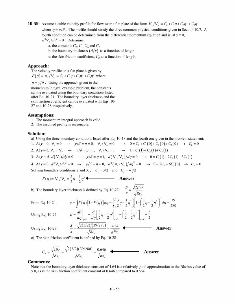
10-59 Assume a cubic velocity profile for flow over a flat plate of the form 2 30 1 2 3x C C C Cη η η∞ = + + +V V
where yη δ= . The profile should satisfy the three common physical conditions given in Section 10.7. A fourth condition can be determined from the differential momentum equation and is: at y = 0,
2 2 0xd dy =V . Determine: a. the constants C0, C1, C2, and C3
b. the boundary thickness ( )xδ as a function of length c. the skin friction coefficient, Cf, as a function of length.
Approach:
The velocity profile on a flat plate is given by ( ) 2
0 1 2 3xF C C C 3Cη η η η∞= = + + +V V where
yη δ= . Using the approach given in the momentum integral example problem, the constants can be evaluated using the boundary conditions listed after Eq. 10-21. The boundary layer thickness and the skin friction coefficient can be evaluated with Eqs. 10-27 and 10-28, respectively.
Assumptions:
1. The momentum integral approach is valid. 2. The assumed profile is reasonable.
Solution:
a) Using the three boundary conditions listed after Eq. 10-18 and the fourth one given in the problem statement: 1. At y = 0, → 0x =V ( ) ( ) ( )0 1 2 3 00, 0 0 0 0 0 0xy C C C Cδ η ∞= = = → = + + + → =V V C
2. At y = δ, → x ∞=V V ( ) ( ) ( )1 2 31, 1 1 1 1 1xy Cδ η ∞= = = → = + +V V C C
3. At y = δ, ( ) 0xd dy =V → ( ) ( ) ( ) (1 2 31, 0 0 1 2 1 3 1xy d d C Cδ η η∞= = = → = + +V V )C
4. At y = 0, 2 2 0xd dy =V → ( ) ( )222 3 20, 0 0 2 6 0 0xy d d C C Cδ η η∞= = = → = + → =V V
Solving boundary conditions 2 and 3: , 1 3 2C = and 3 1 2C = −
( ) 33 12 2xF η η η∞= = −V V Answer
b) The boundary layer thickness is defined by Eq. 10-27: 2
xx Reβ γδ
=
From Eq. 10-24: ( ) ( )1 1
3 3
0 0
3 1 3 1 391 12 2 2 2 280
F F d dγ η η η η η η η η⎡ ⎤⎛ ⎞ ⎛ ⎞= − = − − − =⎡ ⎤ ⎜ ⎟ ⎜ ⎟⎢ ⎥⎣ ⎦ ⎝ ⎠ ⎝ ⎠⎣ ⎦∫ ∫
Using Eq. 10-25: 3 2
00 0
3 1 3 32 2 2 2
dF dd d ηη η
β η η ηη η == =
⎡ ⎛ ⎞= = − = − =⎜ ⎟⎢⎣ ⎝ ⎠
32
Using Eq. 10-27: ( ) ( )2 3 2 39 280 4.64
x xx Re Reδ= = Answer
c) The skin friction coefficient is defined by Eq. 10-28
( )( )2 3 2 39 2802 0.646f
x x x
CRe Re Reβγ
= = = Answer
Comments: Note that the boundary layer thickness constant of 4.64 is a relatively good approximation to the Blasius value of 5.0, as is the skin friction coefficient constant of 0.646 compared to 0.664.
10- 58