Thermal Surfacing Marine & Offshore Industry Solutions€¦ · · 2016-08-02powder consumables...
12
Thermal Surfacing Marine & Offshore Industry Solutions
Transcript of Thermal Surfacing Marine & Offshore Industry Solutions€¦ · · 2016-08-02powder consumables...

Thermal SurfacingMarine & Offshore Industry Solutions

By applying a protective layer of powder consumable,
it is possible to prolong the operating life of new parts and
to refurbish worn. Thus, there is a huge potential for cost
savings and minimising downtimes. In order to achieve
the best results, it is vital to have a thorough knowledge
about how to optimise the combination of powder con-
sumable, process and surfacing treatment technique.
Höganäs’ product portfolio consists of a wide range of
powder consumables suitable for all surfacing techniques.
The focus of this brochure is on overlay welding and
thermal spraying techniques for reconditioning:
• Advancing overlay welding techniques
• Plasma Transferred Arc Welding (PTAW)
• Laser cladding
• Thermal spraying
• Höganäs powders and services
• Quick guide to Höganäs’ powders
2
Höganäs Marine Solutions
Play an Important Protective Role
Figure 1 Overlay welding of shaft
Photo courtesy of Roussakis SA, Greece
Marine engine applications need regular maintenance as a result of wear and corrosion. At some point of time, the parts even have to be replaced by new parts.

3
Welding techniques for achieving metallic coating
layers are characterised by metallurgical bonding to the
substrate. It is very important to be able to control the
process and minimise coating dilution by the substrate.
This ensures the coating layer surface achieves the
specific properties required.
For overlay welding, coating layer thickness can vary
a lot depending on the technique but it should always
achieve the thickness and chemical composition re-
quired. Care must be taken to avoid excessive substrate
temperatures which can lead to deformation and other
undesirable effects.
Why use advanced overlay welding techniques?
Conventional overlay welding techniques such as
Metal Inert Gas (MIG/GMAG), Tungsten Inert Gas (TIG)
and Submerged Arc Welding (SAW) have been and
are still being successfully applied to a wide range of
applications. However, a series of drawbacks, mainly
associated with their high heat input to the workpiece,
can compromise the result or prohibit their use in
some cases.
Advanced overlay welding techniques such as Plasma
Transferred Arc Welding (PTAW) and laser cladding
Advancing Overlay Welding Techniques
Figure 3 Corrosion data comparison for 316L and 2528 laser cladded depositions.
Figure 2 Ni, Cr, Mo and Cu improve corrosion resistance, C and B reduce it.
Corrosion50
40
30
20
10
% Cr
Low High Corrosion Resistance
provide excellent opportunities to improve production and
reconditioning capabilities, reduce costs and enhance
reliability.
Wear and corrosion
There are many forms of wear, from abrasive and
adhesive to erosive that occur in the maritime
environment. Metal to metal wear that occurs between
valves and valve seats is one example. Typically these
surfaces are coated to extend the service interval.
Höganäs’ wear laboratory supports our efforts to
supply high wear resistant materials.
Applications working in corrosive environments, for
instance tail shafts that come in contact with sea water,
require particular protection. A non-porous coating layer
without defects or cracks, deposited with a material
with excellent corrosion resistance, can significantly
minimise the risk of corrosion. The general influence
of the alloying content on corrosion resistance is
illustrated in Figure 2. Pitting corrosion is of particular
interest in sea water environments. The performance of
a Co-based material (2528-00) is compared to a typical
stainless steel (316L) in Figure 3.
Po
tent
ial E
vs
SC
E [V
]
Anodic Polarisation of 316L, 1540, 2528Anodic Polarisation of 316L and 2528
Pot
entia
l E v
s S
CE
[V]
Current [A] 2528 316L

4
PTAW
Main benefits:
• High energy concentration and low heat input to substrate
• Reduced residual stress and distortion
• Low hydrogen technique compared to SAW
• Excellent control of welding bead geometry
• Good process repeatability
• Easy CNC integration
• Suitable with a wide range of filler metals such as cobalt-, nickel-, and iron-based materials as well as carbide cermets
PTAW enables a metallic bonding with the base material with minimal dilution of the substrate (recommended 5-15%). A collimated stream of gas in the plasma state (20 000K) provides the heat required to melt the filler and substrate materials. The gas, typically Argon, is excited inside the welding torch by flowing through an arc formed between a tungsten electrode and a water-cooled copper nozzle. With the aid of a potential difference between the torch and the substrate, the excited gas is driven to the substrate. Powder filler metal is provided coaxially with the nozzle where it is preheated by the plasma gas and flows to the melt pool on the surface of the base material. Shielding gas is also provided coaxially for the protection of the molten materials.
ApplicationsMarine exhaust valve spindles/seats | Co-based hardfacing alloys and Ni-based super alloys are widely used by OEM part manufacturers and reconditioning centres.
Marine valve seats | For applications requiring excellent corrosion and wear resistance, such as valves operating at high temperatures and requiring metal-to-metal sealing.
Pipes and pumping system parts | The lower dilution levels of PTAW offer a good alternative to TIG with hotwire filler material feed.
Figure 4 Marine valve seat (left) and valve (right). Photo courtesy of Abanqobi Spares, South Africa.
Powder grade Particle size µm C % Co % Cr % Mn % Si % B % Ni % Mo % Fe % W % Others %
Nickel-base
625 53-150 ≤ 0.03 - 21.5 - 0.40 - Bal. 9.0 1.4 - Nb = 3.8
718 53-150 < 0.04 Max 1.0 18.0 - Max 0.35 - Bal. 3.0 19.0 -Al = 0.3Ti = 0.9
Nb = 5.11540-00 53-150 0.25 - 7.5 - 3.5 1.6 Bal. - 2.5 - -
1550-00 53-150 0.45 - 11.0 - 3.9 2.3 Bal. - 2.9 - -
Cobalt-base
2528-00 53-150 0.25 Bal. 27.0 - 1.0 - 2.8 5.5 1.5 - -
2537-00 53-150 1.1 Bal. 28.5 - 1.0 - 1.5 - 1.5 4.4 -
2537-10 53-150 1.3 Bal. 28.5 - 1.0 - 1.5 - 1.5 4.4 -
2541-00 53-150 1.4 Bal. 28.5 - 1.1 - 1.5 - 1.0 8.0 -
Iron-base
316L 53-150 ≤ 0.03 - 17.0 1.5 0.8 - 12.0 2.5 Bal. - -
420S 53-150 0.25 - 13.0 1.2 0.5 - <1.0 - Bal. - -
410L 53-150 ≤ 0.03 - 12.5 0.1 0.5 - - - Bal. - -
3533-00 53-150 1.75 - 28.0 0.8 1.3 - 16.0 4.5 Bal. - -
3533-10 53-150 2.1 - 28.0 1.0 1.2 - 11.5 5.5 Bal. - -
PTAW and Laser cladding grades

5
Laser Cladding
Main benefits:• Minimum distortion and residual stress in
reconditioned parts
• Very low dilution levels (<5%) with very fine overlay thicknesses
• Impeccable control of welding bead geometry and overlay thickness attainable
• Local processing capability
• Deposition rates up to more than 12 kg/h
• Good fusion between substrate and filler materials
• Excellent mechanical properties
Laser cladding, a process currently gaining momentum, achieves minimal dilution (< 5%) by precisely controlling thermal input. Minimal heat input to the part gives higher welding quality and efficiency. To melt the substrate and filler metals, a high power laser beam is used. This allows a higher energy concentration in comparison to an arc. All injected energy is confined within a small spot with no diffusion due to convection from hot gas or electromagnetic forces taking place. The filler metal can be added by pre-placing on the workpiece and welded afterwards. Another option is to inject it in the form of powder during welding in a single stage process.
ApplicationsCritical shafts and engine parts | Welding with minimal distortions allows the processing of critical parts such as propeller shafts, crankshafts, pump shafts, camshafts, piston rods, crosshead pins, etc.
Turbomachinery | In-situ laser cladding allows fast and cost-efficient repair of low pressure blades of steam turbines. Small turbo rotors can be repaired without distortion.
Other parts | Local repairs can be made on cast iron parts, such as expensive cylinder cover castings, and pump impellers at minimum cost and post machining.
The lower dilution of laser achieves the correct material chemistry after 1 layer with 1 mm height. The MIG/GMAG process requires 3 layers and 8 mm (see Figure 5).
Powder grade HardnessHRC HV30
Melting range (°C)
Thermal expansion co-efficient (10-6/°C)
Hall flow (sec/50g)
Density (g/cm3)
Recommended use /Features/Comments
Nickel-base
625 200* 1290-1350 15.6 (20-800°C) 14.2 8.4 IN 625 1)
718 240* 1200-1300 16.0 (25-800°C) 15.5 - IN 718 1)
1540-00 40* 1010-1140 14.4 (25-600°C) 15.4 8.1
1550-00 52* 1000-1110 13.6 (20-600°C) 15.4 7.9
Cobalt-base
2528-00 340* 1185-1385 15.6 (20-800°C) 15.7 8.3 Stellite 21 2)
2537-00 41* 480 1285-1375 15.6 (20-800°C) 15.8 8.3 Stellite 6 2)
2537-10 43* 1285-1375 15.6 (20-800°C) 15.8 8.3 Stellite 6 2)
2541-00 44* 1280-1315 15.2 (20-800°C) 16.4 8.5 Stellite 12 2)
Iron-base
316L 160* 1375-1430 19.5 (20-800°C) 16.4 7.9 316L 3)
420S 55* - - -
410L 220* 1480-1530 - 14.5 - 416L 3)
3533-00 33* 1220-1320 - 15.0 7.8
3533-10 42* - 16.1 (25-800°C) 14.8 7.7
Figure 5 Laser cladding requires less machining than MIG/GMAG to reach final dimensions after deposition. This is due to the bead form or shape and the overlap.
8 mm
MIG - wire
Laser - powder
1 mm
8 mm
MIG - wire
Laser - powder
1 mm
MIG - wire
8 mm
1 mmLaser - powder
* Value measured after PTAW

6
Powder grade Particle size µm C % Co % Cr % Mn % Si % B % Ni % Mo % Fe % W % Others %
Nickel-base
1660-02 20-53 0.75 - 14.8 - 4.3 3.1 Bal. - 3.7 - -
1660-02+WC 20-53 - - - - - - - - - - -
Cobalt-base
2628-02 20-53 0.25 Bal. 27.0 - 0.9 - 2.5 5.5 1.5 - -
2637-02 20-53 1.1 Bal. 28.5 - 1.0 - 1.5 - 1.5 4.4 -
Iron-base
316L 20-53 ≤ 0.03 - 17.0 1.5 0.8 - 12.0 2.5 Bal. - -
3650-02 20-53 1.75 - 28.0 0.8 1.3 - 16.0 4.5 Bal. - -
Plasma and HVOF spraying grades
Thermal Spraying
Thermal spraying includes techniques where a hot filler material, is sprayed with high velocity against the workpiece to create an overlay. Many applications in the marine industry are repaired by the available techniques described below.
Flame SprayBy utilising combustible gas such as hydrogen, acetylene, propane and natural gas, the flame spray process creates the energy required to soften the coating material. The semi-molten particles flatten under impact and interlock with the base material and with each other to form a mechanical bond. To form a dense coating strongly adhered to the substrate, spraying is typically followed by a fusing process. This can be achieved by passing a gas torch over the deposit at about 1000°C or by heating in a furnace with controlled atmosphere.
Applications• Restoration of various parts, for example bearing
journals and rotor shaft sealing areas.
Plasma SprayThis method employs a technique essentially similar to flame spraying. It differs in that the flame comprises
an electrically excited plasma of high velocity and temperature (≈15 000K). This permits a denser coating (95-98%). Deposition rates are from 2–8 kg/hour, and surfacing thickness from 0.1–2.5 mm.
High Velocity Oxygen Fuel (HVOF) HVOF is a thermal spraying process using high gas velocity. Fuel and oxygen is combined to create rapidly expanding combustion gases inside a specially designed combustion nozzle. At speeds around 5 Mach, the powder filler metal is accelerated through the flame. In most HVOF systems, the transient time of particles within the flame is such that they do not melt. The melting process is supported by the plasticising of particles as they collide with the substrate. This feature is particularly useful when applying carbide cermets where the carbide particles should remain below melting temperatures and retain their properties. The high collision velocities allow for very dense (< 0.5 % porosity) and uniform coatings with excellent adhesion, wear and corrosion properties.
Applications• Hydraulic piston rods• Two -stroke engine piston rods• Exhaust valve stems

Powder grade HardnessHRC HV30
Melting range (°C)
Hall flow (sec/50g)
Density (g/cm3)
Recommended use /Features/Comments
Nickel-base
1660-02 780* 970-1200 12.6 7.7
1660-02+WC - - -
Cobalt-base
2628-02 300** 1185-1385 11.5 - Stellite 21 2)
2637-02 380* 1275-1375 11.6 - Stellite 6 2)
Iron-base
316L 160** 1275-1430 13.0 7.9 316L 3)
3650-02 500** 1220-1320 13.1 7.8
* Indicative value** Measured value
7
Valve stemPowder: WCMethod: HVOF

8
Höganäs Powders
Recommendations for overlay welding and
thermal spray
Höganäs manufactures a wide range of metallic materials
with a proven track record including the compositions
required for marine and offshore applications. These are
available in a range of particle size intervals to function in
all equipment brands.
It is important to choose the right powder grade, chemical
composition and hardness etc., but also the right particle
size range. Our powder grades have seven main standard
sieve ranges (see Figure 6).
Choice of material
Classification society rules specify the material suitable
for each application. Based on these recommendations
a range of materials can be seen on page 11.
Particle size range
PTA welding /Laser cladding
Flame sprayingPowder weldingHVOF spraying
0
1
2 2-01
5
6
6-05
6-02
7
3
6-01
μm
150
125
106
7163
53
45
36
2010
212
Figure 6

Recommended Storage Conditions
9
• Bottles should be tightly sealed at all times
during storage
• Opened bottles must be resealed immediately
after use
• Bottles should be stored in clean and dry
conditions at all times
• Storage temperatures of 15- 25°C are
considered optimum
Powder designations1 6 20 – 1 1 A B C – D EA: Alloy Base 1 = Nickel (Ni) 2 = Cobalt (Co) 3 = Iron (Fe) 4 = Tungsten Carbide (WC)B: Standard Particle Size Range 0 = 20 – 106 µm 1 = 20 – 71 µm 2 = 36 – 106 µm 3 = 45 – 125 µm 5 = 53 – 150 µm 6 = 15 – 53 µm 7 = 63 – 212 µmC: Average Hardness: Rockwell CD: Chemical Composition 1–9 = modified E: Particle Size Range 1–9 = modified
Foot notes1) Registered trademark Inco Corp.2) Registered trademark Kennametal Stellite3) A.I.S.I. standard4) Spherical particles5) This sieve is especially designed for HVOF
Important
Shake bottles well before use. No large and fast tem-
perature changes should occur during storage as this will
cause humidity inside the cap even when it is sealed.
If for some reason the powder moisture content has
increased this can be lowered by drying. Dry the powder
at 80°C (max 100°C) for one hour. Preferably under
rotation for best effect.
Services
Independent consulting service for laser cladding may
be requested for choice and enabling of equipment, staff
training and as a speaking partner – request quote.
Classification societies may require the preparation of
welding coupons that will be used for the construction
of specimens for mechanical testing. As a technical
service, we can provide customers with coupon
evaluation – request quote.

Schematics of marine engine.
11
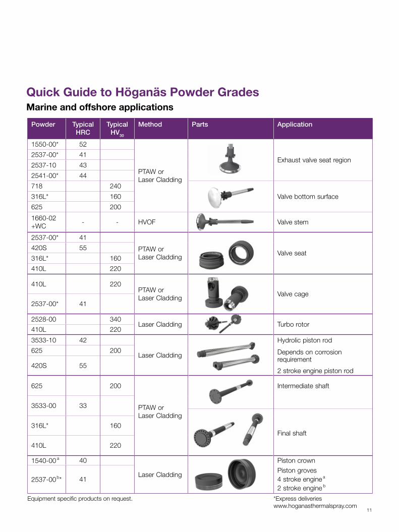
Quick Guide to Höganäs Powder GradesMarine and offshore applications
Powder Typical HRC
Typical HV30
Method Parts Application
1550-00* 52
PTAW or Laser Cladding
Exhaust valve seat region2537-00* 41
2537-10 43
2541-00* 44
718 240
Valve bottom surface316L* 160
625 200
1660-02 +WC
- - HVOF Valve stem
2537-00* 41
PTAW or Laser Cladding
Valve seat420S 55
316L* 160
410L 220
410L 220 PTAW or Laser Cladding
Valve cage2537-00* 41
2528-00 340 Laser Cladding Turbo rotor
410L 220
3533-10 42
Laser Cladding
Hydrolic piston rod
625 200 Depends on corrosion requirement
420S 55 2 stroke engine piston rod
625 200
PTAW or Laser Cladding
Intermediate shaft
3533-00 33
316L* 160Final shaft
410L 220
1540-00 a 40
Laser Cladding
Piston crown
2537-00b* 41Piston groves4 stroke engine a
2 stroke engine b
Equipment specific products on request. *Express deliveries www.hoganasthermalspray.com
Metal powder technology has the power to open up a world
of possibilities. The inherent properties of metal powders provide
unique possibilities to tailor solutions to match your requirements.
This is what we call Power of Powder, a concept to constantly
widen and grow the range of metal powder applications.
With its leading position in metal powder technology, Höganäs
is perfectly placed to help you explore those possibilities as your
application project partner.
Power of Powder is being applied far beyond its traditional role
in the production of components for vehicles. Iron powder
is used in food fortification to combat anaemia. Nickel powders
are vital ingredients in valve coatings to enhance wear resistance.
Specially formulated iron-based powders offer new solutions
for high-temperature brazing. Soft Magnetic Composites with
3D magnetic properties are opening the way for innovative
electric motors. In fact, metal powder technology generates
virtually endless possibilities.
To find out how you can apply the Power of Powder, please
contact your nearest Höganäs office.
www.hoganasthermalspray.com | www.hoganas.com
Sweden
Brazil
China
France
Germany
India
Italy
Japan
Rep. of Korea
Russia
Spain
Taiwan
United Kingdom
United States
Höganäs ABHöganäsPhone +46 42 33 80 [email protected]
Höganäs Brasil LtdaMogi das CruzesPhone +55 11 4793 [email protected]
Höganäs (China) Co. LtdShanghai Phone +86 21 670 010 [email protected]
Höganäs France S.A.S.Villefranche-sur-Saône CedexPhone +33 474 02 97 [email protected]
Höganäs GmbHDüsseldorfPhone +49 211 99 17 [email protected]
Höganäs India Pvt LtdPune Phone +91 20 66 03 01 [email protected]
Höganäs Italia S.r.l.Rapallo (Genoa)Phone +39 0185 23 00 [email protected]
Höganäs Japan K.K.Tokyo Phone +81 3 3582 [email protected]
Höganäs Korea LtdSeoul Phone +82 2 511 43 [email protected]
Höganäs East Europe LLCSaint PetersburgPhone +7 812 334 25 [email protected]
Höganäs Ibérica S.A.MadridPhone +34 91 708 05 [email protected]
Höganäs Taiwan LtdTaipei Phone +886 2 2543 [email protected]
Höganäs (Great Britain) LtdTonbridge, Kent Phone +44 1732 377 [email protected]
North American Höganäs, Inc.Hollsopple: PAPhone +1 814 479 [email protected]
Power of Powder®
© H
ögan
äs A
B (p
ubl.)
, May
201
3.
0441
HO
G