
THERMAL PRINTER TSP650II SERIES - Star Micronics · Federal Communications Commission Radio...
33
THERMAL PRINTER TSP 650II SERIES Hardware Manual
Transcript of THERMAL PRINTER TSP650II SERIES - Star Micronics · Federal Communications Commission Radio...

THERMAL PRINTER
TSP650II SERIES
Hardware Manual
Federal Communications CommissionRadio Frequency Interference
Statement
This device complies with Part 15 of FCC Rules and Industry Canada licence-exempt RSS standard(s). Operation is subject to the following two conditions: (1) This device may not cause harmful interference, and (2) this device must accept any interference received, including interference that may cause undesired operation.
Le présent appareil est conforme aux CNR d'Industrie Canada applicables aux appareils radio exempts de licence. L'exploitation est autorisée aux deux conditions suivantes : (1) l'appareil ne doit pas produire de brouillage, et (2) l'utilisateur de l'appareil doit accepter tout brouillage radioélectrique subi, même si le brouillage est susceptible
d'en compromettre le fonctionnement.
FCC CAUTIONChanges or modifications not expressly approved by the party responsible for compliance could void the user’s authority to operate the equipment.For compliance with the Federal Noise Interference Standard, this equipment requires a shielded cable.For RF interference suppression, if a ferrite core is provided with this device, affix it to the interface cable.
NOTE: This equipment has been tested and found to comply with the limits for a Class A digital device, pursuant to Part 15 of the FCC Rules. These limits are designed to provide reasonable protection against harmful interference when the equipment is operated in a commercial environment. This equipment generates, uses and can radiate radio frequency energy and, if not installed and used in accordance with the instruction manual, may cause harmful interference to radio communications. Operation of this equipment in a residential area is likely to cause harmful interference in which case the user will be required to correct the interference at his own expense.CAN ICES-3 (A) / NMB-3 (A)
This equipment complies with FCC/IC radiation exposure limits set forth for an uncontrolled environment and meets the FCC radio frequency (RF) Exposure Guidelines in Supplement C to OET65 and RSS-102 of the IC radio frequency (RF) Exposure rules. This equipment has very low levels of RF energy that it deemed to comply without maximum permissive exposure evaluation(MPE). But it is desirable that it should be installed and operated keeping the radiator at least 20cm or more away from person's body (excluding extremities: hands,wrists,feet and ankles).
Cet équipement est conforme aux limites d"exposition aux rayonnements énoncées pour un environnement non contrôlé et respecte les règles les radioélectriques (RF) de la FCC lignes directrices d'exposition dans le Supplément C à OET65 et d"exposition aux fréquences radioélectriques (RF) CNR-102 de l"IC. Cet équipement émet une énergie RF très faible qui est considérée conforme sans évaluation de l"exposition maximale autorisée. Cependant, cet équipement doit être installé et utilisé en gardant une distance de 20 cm ou plus entre le dispositif rayonnant et le corps (à l"exception des extrémités : mains, poignets, pieds et chevilles).

國家通訊傳播委員會國家通訊傳播委員會國家通訊傳播委員會國家通訊傳播委員會(NCC)(NCC)(NCC)(NCC)警告警告警告警告
根據「低功率電波輻射性電機管理辦法」第十條
製造、輸入或販賣低功率射頻電機者,應於低功率射頻電機使用說明書內加
印第十二條及第十四條之規定內容。
「低功率電波輻射性電機管理辦法」第十二條
經型式認證合格之低功率射頻電機,非經許可,公司、商號或使用者均不得
擅自變更頻率、加大功率或變更原設計之特性及功能。
「低功率電波輻射性電機管理辦法」第十四條
低功率射頻電機之使用不得影響飛航安全及干擾合法通信;經發現有干擾現
象時,應立即停用,並改善至無干擾時方得繼續使用。
前項合法通信,指依電信法規定作業之無線電通信。
低功率射頻電機須忍受合法通信或工業、科學及醫療用電波輻射性電機設備
之干擾。
Trademark acknowledgmentsTSP650II : Star Micronics Co., Ltd.
Notice• All rights reserved. Reproduction of any part of this manual in any form whatsoever, without STAR’s express
permission is forbidden.• The contents of this manual are subject to change without notice.• All efforts have been made to ensure the accuracy of the contents of this manual at the time of going to press.
However, should any errors be detected, STAR would greatly appreciate being informed of them.• The above notwithstanding, STAR can assume no responsibility for any errors in this manual.
• IOS is a trademark or registered trademark of Cisco in the U.S. and other countries and is used under license.• Android is a trademark of Google Inc.• Windows is registered trademarks of Microsoft Corporation.• Bluetooth® wordmark and logo are registered trademarks owned by Bluetooth SIG, Inc.
Copyright © 2013-2018 Star Micronics Co., Ltd..
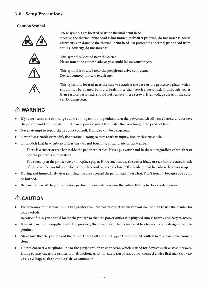
Caution Symbol
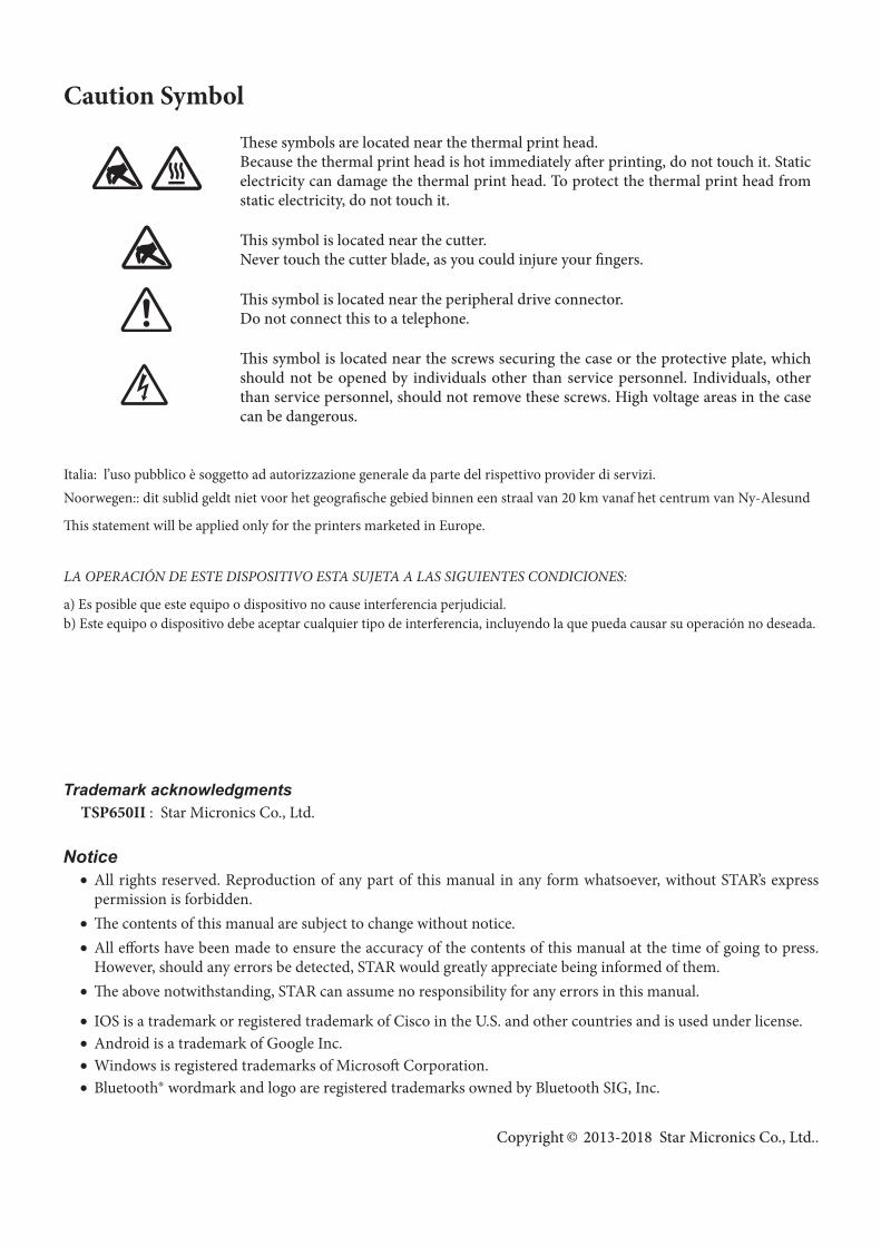
These symbols are located near the thermal print head.Because the thermal print head is hot immediately after printing, do not touch it. Static electricity can damage the thermal print head. To protect the thermal print head from static electricity, do not touch it.
This symbol is located near the cutter. Never touch the cutter blade, as you could injure your fingers.
This symbol is located near the peripheral drive connector.Do not connect this to a telephone.
This symbol is located near the screws securing the case or the protective plate, which should not be opened by individuals other than service personnel. Individuals, other than service personnel, should not remove these screws. High voltage areas in the case can be dangerous.
Italia: l’uso pubblico è soggetto ad autorizzazione generale da parte del rispettivo provider di servizi. Noorwegen:: dit sublid geldt niet voor het geografische gebied binnen een straal van 20 km vanaf het centrum van Ny-Alesund
This statement will be applied only for the printers marketed in Europe.
LA OPERACIÓN DE ESTE DISPOSITIVO ESTA SUJETA A LAS SIGUIENTES CONDICIONES:
a) Es posible que este equipo o dispositivo no cause interferencia perjudicial.b) Este equipo o dispositivo debe aceptar cualquier tipo de interferencia, incluyendo la que pueda causar su operación no deseada.

Declaration of ConformityKonformitätserklärungDéclaration de conformitéDeclaración de conformidadDichiarazione di conformitàVerklaring van conformiteitIzjava o sukladnostiIzjava o skladnostiProhlášení o shoděUyumluluk BeyanıMegfelelőségi nyilatkozatOverensstemmelseserklæringFörsäkran om överensstämmelseVaatimuksenmukaisuusvakuutusKonformitetserklæringDeclaração de ConformidadeΔήλωση συμμόρφωσηςDeklaracja zgodnościVyhlásenie o zhodeVastavusdeklaratsioonAtbilstības deklarācijaAtitikties deklaracijaDikjarazzjoni ta' KonformitàDeclaraţie de conformitateДекларация за съответствиеDearbhú Comhréireachta
http://www.starmicronics.com/support/mannualfolder/TSP650_CE_DoC_Newest.pdf
TABLE OF CONTENTS
1. Unpacking and Installation ......................................................................... 11-1. Unpacking .................................................................................................... 11-2. Notes about Installation ............................................................................... 1
2. Parts Identification and Nomenclature ....................................................... 2
3. Setup ............................................................................................................ 33-1. Connecting the Interface Cable to the PC ...................................................... 33-2. Connecting the Interface Cable to the Printer ���������������������������������������������� 43-3. Connecting the AC Adapter .......................................................................... 73-4. Turning the Power On ................................................................................... 83-5. Connecting to a Peripheral Device ................................................................ 83-6. Loading a Paper Roll ..................................................................................... 93-7. Bluetooth Settings (For Bluetooth Interface Models only) ............................... 12
3-8. Setup Precautions ....................................................................................... 17
4. Attaching the Accessories ........................................................................... 194-1. Attaching the Holder Plate .......................................................................... 194-2. Attaching the Rubber Feet .......................................................................... 214-3. Switch Cover Installation ............................................................................ 21
5. Adjusting the Near-end Sensor .................................................................. 22
6. Error Indicators ......................................................................................... 236-1. Recoverable errors ...................................................................................... 236-2. Unrecoverable errors .................................................................................. 23
7. Preventing and Removing Paper Jams ...................................................... 247-1. Preventing Paper Jams ................................................................................ 247-2. Removing Paper Jams ................................................................................. 247-3. Releasing the Cutter Lock ........................................................................... 25
8. Maintenance ............................................................................................... 268-1. Thermal Head ............................................................................................. 268-2. Platen Rubber Roller .................................................................................. 268-3. Paper Holder .............................................................................................. 26
- 1 -
1. Unpacking and Installation
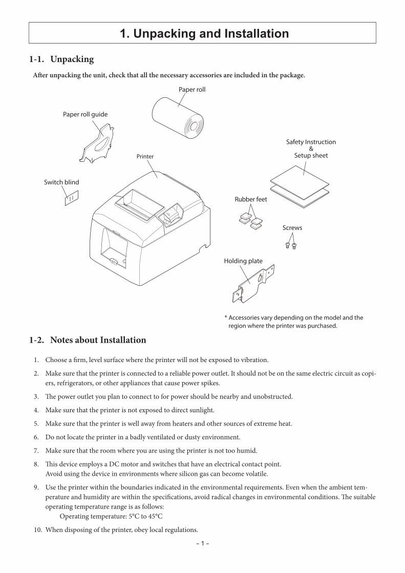
* Accessories vary depending on the model and the region where the printer was purchased.
Paper roll
Printer
Holding plate
Screws
Switch blind
Safety Instruction&
Setup sheet
Paper roll guide
Rubber feet
1-1. UnpackingAfter unpacking the unit, check that all the necessary accessories are included in the package.
1-2. Notes about Installation
1. Choose a firm, level surface where the printer will not be exposed to vibration.
2. Make sure that the printer is connected to a reliable power outlet. It should not be on the same electric circuit as copi-ers, refrigerators, or other appliances that cause power spikes.
3. The power outlet you plan to connect to for power should be nearby and unobstructed.
4. Make sure that the printer is not exposed to direct sunlight.
5. Make sure that the printer is well away from heaters and other sources of extreme heat.
6. Do not locate the printer in a badly ventilated or dusty environment.
7. Make sure that the room where you are using the printer is not too humid.
8. This device employs a DC motor and switches that have an electrical contact point. Avoid using the device in environments where silicon gas can become volatile.
9. Use the printer within the boundaries indicated in the environmental requirements. Even when the ambient tem-perature and humidity are within the specifications, avoid radical changes in environmental conditions. The suitable operating temperature range is as follows: Operating temperature: 5°C to 45°C
10. When disposing of the printer, obey local regulations.
- 2 -
ERRORFEED
POWER
TSP650
2. Parts Identification and Nomenclature
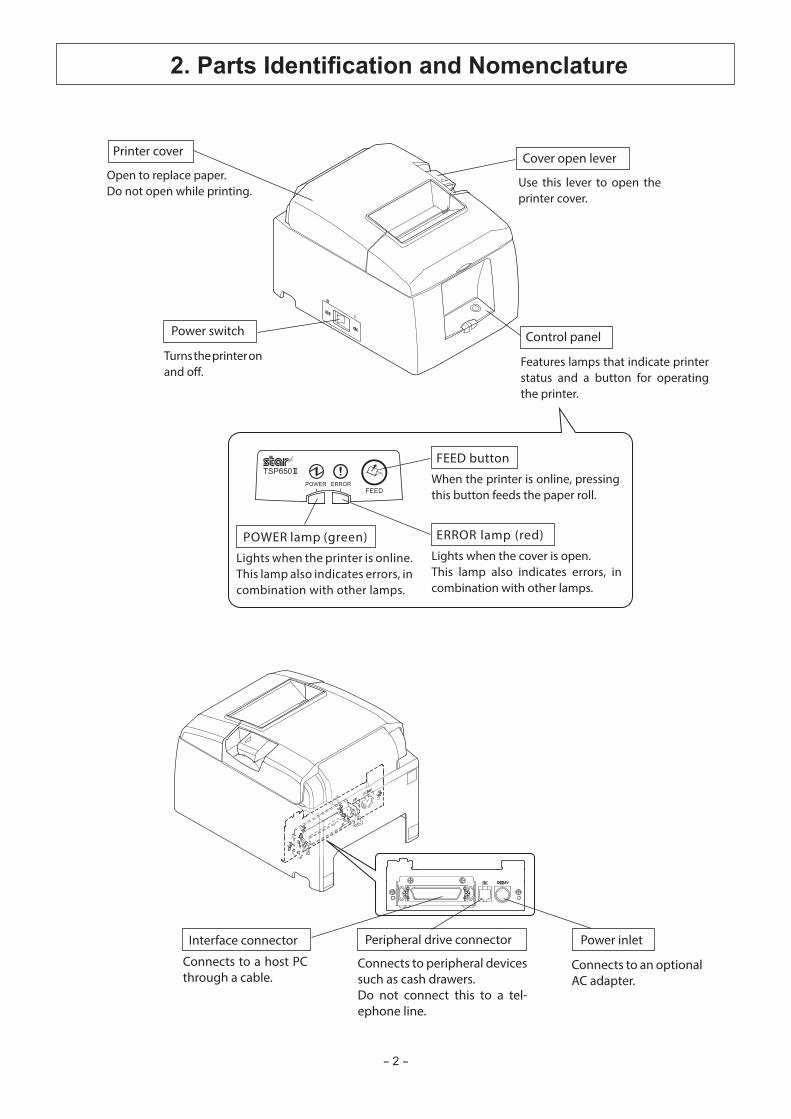
Control panel
Features lamps that indicate printer status and a button for operating the printer.
Printer cover
Open to replace paper.Do not open while printing.
Power switch
Turns the printer on and off.
Connects to peripheral devices such as cash drawers.Do not connect this to a tel-ephone line.
Peripheral drive connector
Connects to an optional AC adapter.
Power inlet
Connects to a host PC through a cable.
Interface connector
Lights when the printer is online.This lamp also indicates errors, in combination with other lamps.
POWER lamp (green)Lights when the cover is open.This lamp also indicates errors, in combination with other lamps.
ERROR lamp (red)
When the printer is online, pressing this button feeds the paper roll.
FEED button
Cover open lever
Use this lever to open the printer cover.

- 3 -
3. Setup
3-1. Connecting the Interface Cable to the PC
3-1-1. Parallel Cable
Connect the parallel cable to a parallel port on your PC.
3-1-2. RS-232C Cable
Connect the RS-232C cable to a RS-232C port on your PC.
3-1-3. USB Cable
Connect the USB cable to a USB port on your PC.
3-1-4. Ethernet Cable
Connect the Ethernet cable to a USB port on your PC.
- 4 -
Parallel interface cable
Ferrite core
Interface cable
5 cm(maximum)
Fastener
Pull and cut
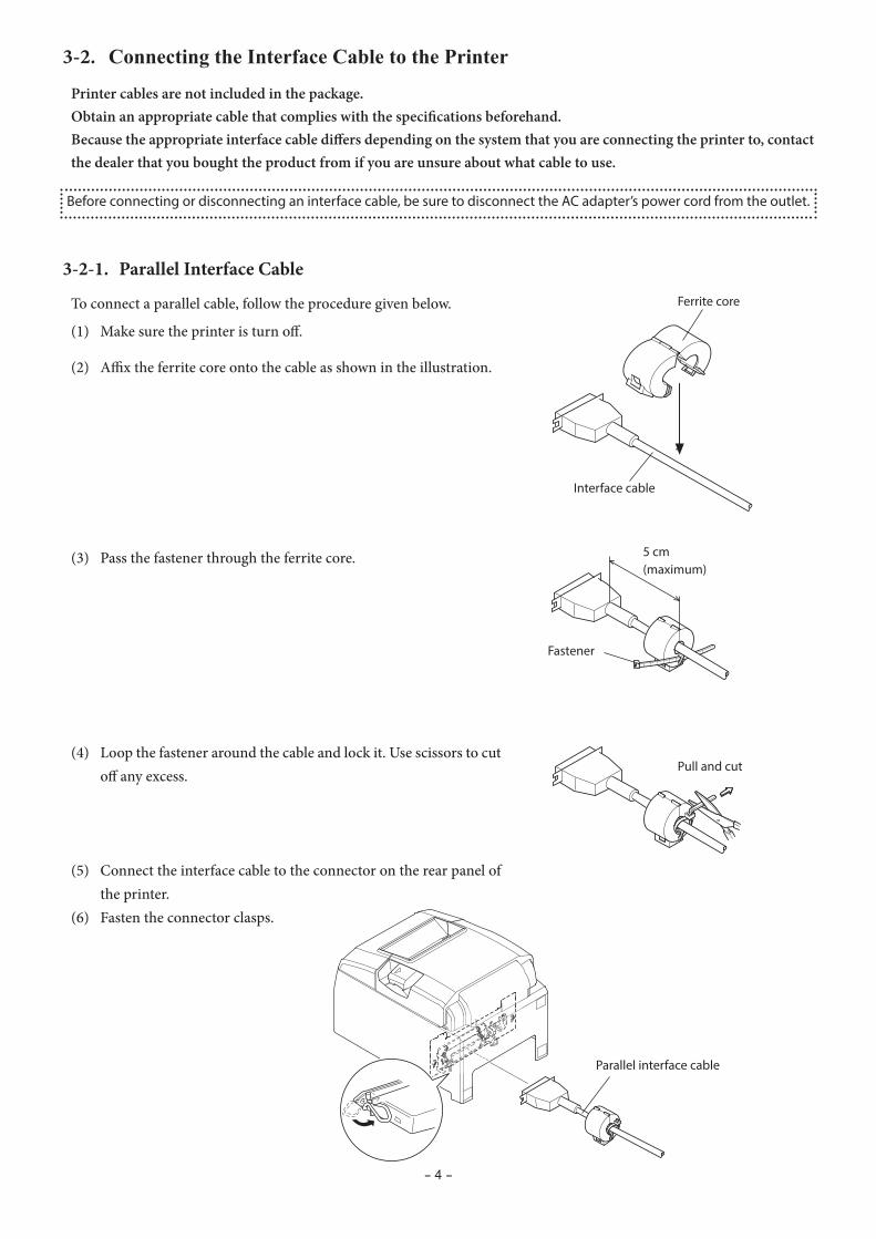
3-2. Connecting the Interface Cable to the Printer
Printer cables are not included in the package.Obtain an appropriate cable that complies with the specifications beforehand.Because the appropriate interface cable differs depending on the system that you are connecting the printer to, contact the dealer that you bought the product from if you are unsure about what cable to use.
Before connecting or disconnecting an interface cable, be sure to disconnect the AC adapter’s power cord from the outlet.
3-2-1. Parallel Interface Cable
To connect a parallel cable, follow the procedure given below.
(1) Make sure the printer is turn off.
(2) Affix the ferrite core onto the cable as shown in the illustration.
(3) Pass the fastener through the ferrite core.
(4) Loop the fastener around the cable and lock it. Use scissors to cut off any excess.
(5) Connect the interface cable to the connector on the rear panel of the printer.
(6) Fasten the connector clasps.
- 5 -
RS-232C interface cable
USB cable
Cable hook
4 cm (maximum)
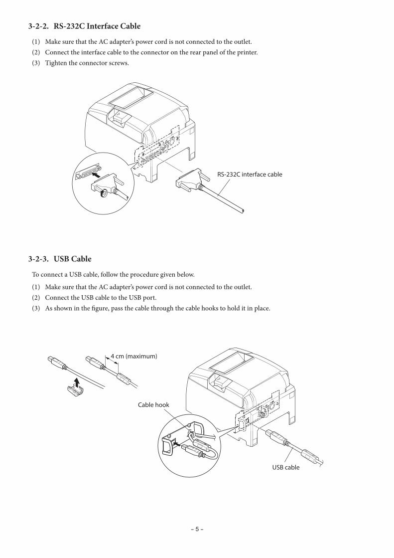
3-2-2. RS-232C Interface Cable
(1) Make sure that the AC adapter’s power cord is not connected to the outlet.(2) Connect the interface cable to the connector on the rear panel of the printer.(3) Tighten the connector screws.
3-2-3. USB Cable
To connect a USB cable, follow the procedure given below.
(1) Make sure that the AC adapter’s power cord is not connected to the outlet.(2) Connect the USB cable to the USB port.(3) As shown in the figure, pass the cable through the cable hooks to hold it in place.
- 6 -
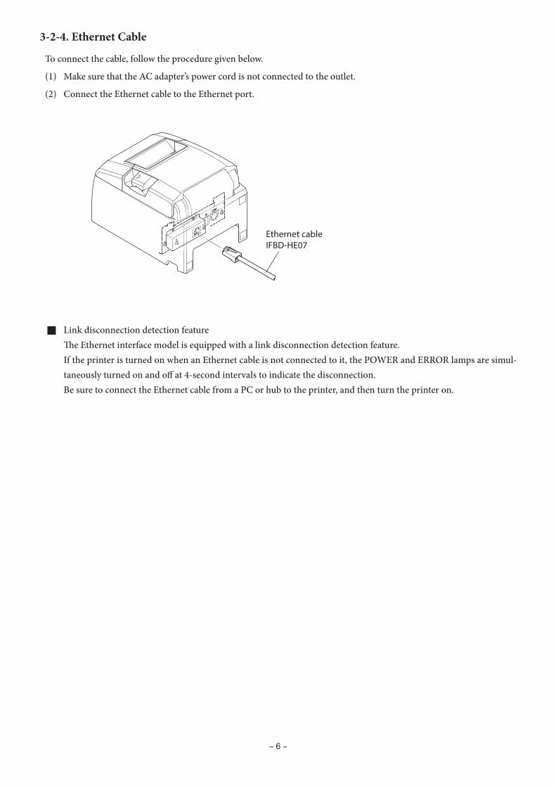
Ethernet cableIFBD-HE07
3-2-4. Ethernet Cable
To connect the cable, follow the procedure given below.
(1) Make sure that the AC adapter’s power cord is not connected to the outlet.
(2) Connect the Ethernet cable to the Ethernet port.
g Link disconnection detection feature The Ethernet interface model is equipped with a link disconnection detection feature. If the printer is turned on when an Ethernet cable is not connected to it, the POWER and ERROR lamps are simul-
taneously turned on and off at 4-second intervals to indicate the disconnection. Be sure to connect the Ethernet cable from a PC or hub to the printer, and then turn the printer on.
- 7 -
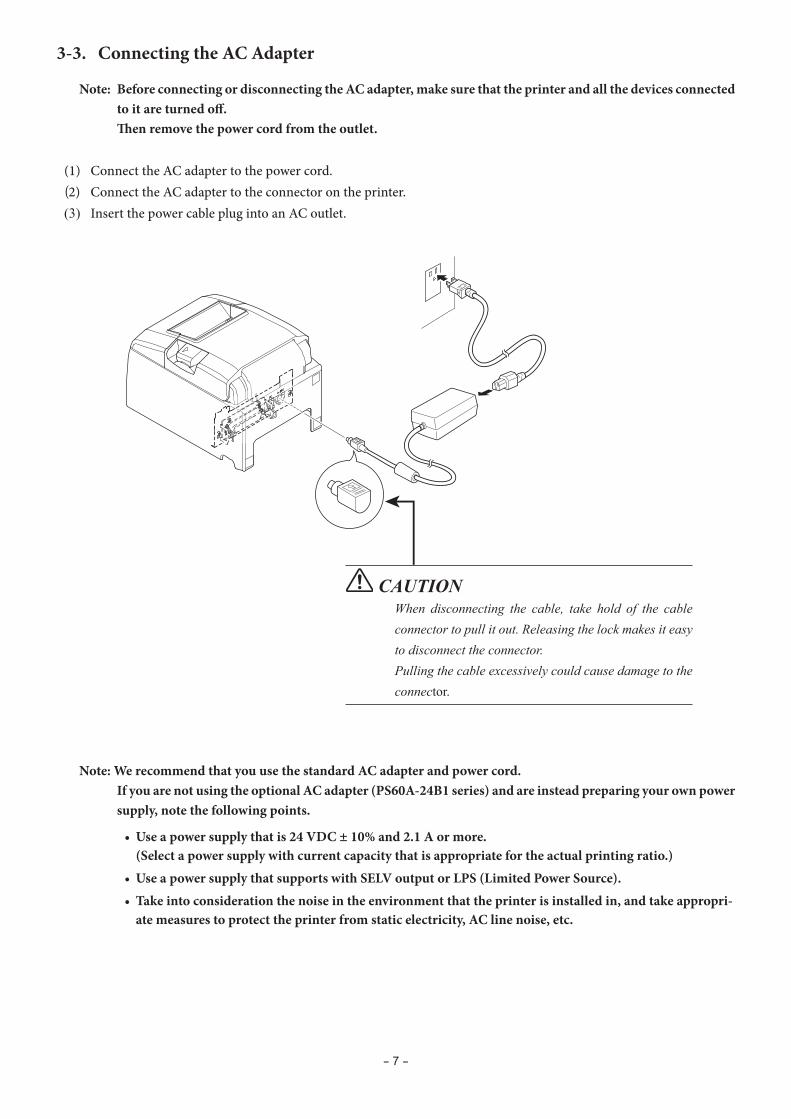
3-3. Connecting the AC Adapter
Note: Before connecting or disconnecting the AC adapter, make sure that the printer and all the devices connected to it are turned off.
Then remove the power cord from the outlet.
(1) Connect the AC adapter to the power cord.(2) Connect the AC adapter to the connector on the printer.(3) Insert the power cable plug into an AC outlet.
CAUTION When disconnecting the cable, take hold of the cable connector to pull it out. Releasing the lock makes it easy to disconnect the connector.Pulling the cable excessively could cause damage to the connector.
Note: We recommend that you use the standard AC adapter and power cord. If you are not using the optional AC adapter (PS60A-24B1 series) and are instead preparing your own power
supply, note the following points.
• Use a power supply that is 24 VDC ± 10% and 2.1 A or more. (Select a power supply with current capacity that is appropriate for the actual printing ratio.)
• Use a power supply that supports with SELV output or LPS (Limited Power Source).• Take into consideration the noise in the environment that the printer is installed in, and take appropri-
ate measures to protect the printer from static electricity, AC line noise, etc.

- 8 -
Power switch
3-4. Turning the Power On
Connect the power cord according to the procedure in section 3-3, “Connecting the AC Adapter”.
Turn on the power switch, which is on the left side of the printer. The POWER lamp on the control panel will light.
3-5. Connecting to a Peripheral Device
You can connect a peripheral device to the printer using a modular plug.Follow the procedure given below.
1) Make sure that the AC adapter’s power cord is not connected to the outlet.2) Connect the modular jack plug to the peripheral drive connector on the rear panel of the printer.
Connect the other end of the cable to the modular jack of the peripheral device.
CAUTION: Do not connect a telephone line to the peripheral drive connector. Doing so may cause the printer to malfunction. Also, for safety purposes, do not connect a wire that may carry excessive voltage to the peripheral drive connector.
- 9 -
Cover open lever
Paper roll
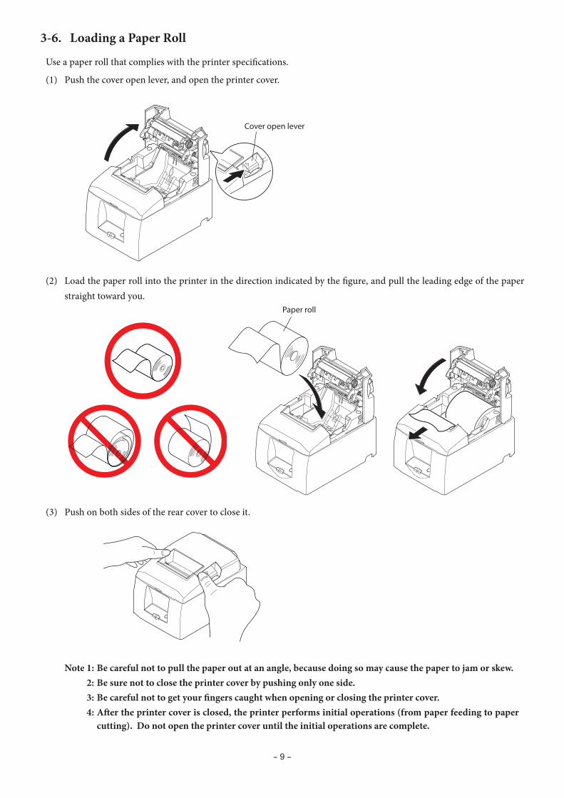
3-6. Loading a Paper Roll
Use a paper roll that complies with the printer specifications.
(1) Push the cover open lever, and open the printer cover.
(2) Load the paper roll into the printer in the direction indicated by the figure, and pull the leading edge of the paper straight toward you.
(3) Push on both sides of the rear cover to close it.
Note 1: Be careful not to pull the paper out at an angle, because doing so may cause the paper to jam or skew. 2: Be sure not to close the printer cover by pushing only one side. 3: Be careful not to get your fingers caught when opening or closing the printer cover. 4: After the printer cover is closed, the printer performs initial operations (from paper feeding to paper
cutting). Do not open the printer cover until the initial operations are complete.

- 10 -
3-6-1. Compliant Paper Roll Specifications
Paper thickness 53 μm to 85 μm
Paper width79.5 ± 0.5 mm57.5 ± 0.5 mm
External dimensions
• Roll diameter Max. f83 mm
• Take up paper roll width 80 +0.5 mm / 58 +0.5 mm
Core inner and outer diameters Inner diameter f12 ± 1 mm, external diameter f18 ± 1 mm
Printed surface Outer edge of roll
Note 1: Do not glue or tape the paper roll and shaft core together. 2: Do not fold the tail end of the paper. 3: For details on recommended thermal paper, see the following webpage. http://www.starmicronics.com/support/
- 1- 1
- 11 -
Paper roll guide
A
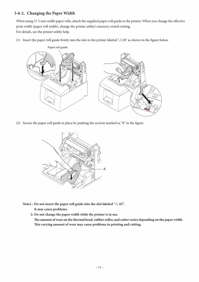
3-6-2. Changing the Paper Width
When using 57.5 mm width paper rolls, attach the supplied paper roll guide to the printer. When you change the effective print width (paper roll width), change the printer utility’s memory switch setting. For details, see the printer utility help.
(1) Insert the paper roll guide firmly into the slot in the printer labeled "r58" as shown in the figure below.
(2) Secure the paper roll guide in place by pushing the section marked as “A” in the figure.
Note1 : Do not insert the paper roll guide into the slot labeled "r 65". It may cause problems. 2: Do not change the paper width while the printer is in use. The amount of wear on the thermal head, rubber roller, and cutter varies depending on the paper width.
This varying amount of wear may cause problems in printing and cutting.

- 12 -
PAIR
RST
PAIR
RST
PAIRRST
PAIR button
PAIR buttonRST button
LED
< iOS > < Android >
Flashing green LED
3-7. Bluetooth Settings (For Bluetooth Interface Models only)
(2) After turning the printer's power switch on, press and hold the PAIR button on the rear interface of the printer for 5 seconds or more, and then release it. The LED will flash green.
Pair the printer with the master device by following the procedure below.Compatibility list: http://www.star-m.jp/prjump/000031.html
3-7-1. Pairing using SSP (Simple Secure Pairing) [Default]
(1) Working on the master device, tap [Settings] and set [Bluetooth] to ON.
<LED> Indicates the status of the Bluetooth interface. Green (on): Not connected. Green (flashing): Ready to start pairing. Blue (on): Connected. Purple (flashing): Auto connection ON.
(3) Pairing will be possible for 60 seconds from when the LED begins flashing green. During this time, execute "Search for devices" from the master device and tap the relevant device from the displayed list.
Device name: Star Micronics (default)
(4) In an iOS device, after pairing, the LED will automatically begin flashing blue, and the printer will be automatically connected. In an Android device, the LED turns blue only while data is sent.
(5) Connect to the printer from the master device application and perform printing. If the printing is successful, the pairing process has been completed.
- 13 -
ERRORFEED
POWER
TSP650
Note: The printer performs various processes immediately after connecting to or disconnecting from a master device.
Please wait approximately 0.1 seconds after connecting, and approximately 0.5 seconds after disconnecting, before beginning communications with the printer.
3-7-2. Pairing using PIN code
Enter the following information in the master device if it does not support SSP, or when otherwise necessary.
PIN: 1234 (default)
Device name: Star Micronics (default)
It is recommended that you change the PIN code for greater security.For details regard changing the PIN code, please see the “Software Manual -Star Bluetooth Utility- ”.
3-7-3. Auto Connection Function (iOS only)
Each time the wireless connection is disconnected while communicating with upper-level iOS devices including iPad over Bluetooth, it is necessary to move back to the Bluetooth setting screen in the upper-level iOS device and tap the desired printer name again to build a connection. This is an iOS specification. In order to save this labor, this printer is equipped with the Auto Connection function that automatically requests a con-nection from an upper-level iOS device that was connected to the printer last time.
The default setting of this function may differ according to the printer model you are using. Confirm the default settings for your printer, as well as the use examples for ON/OFF settings, and then make the settings to match your purpose.You can also check the current ON/OFF setting by performing self-printing.
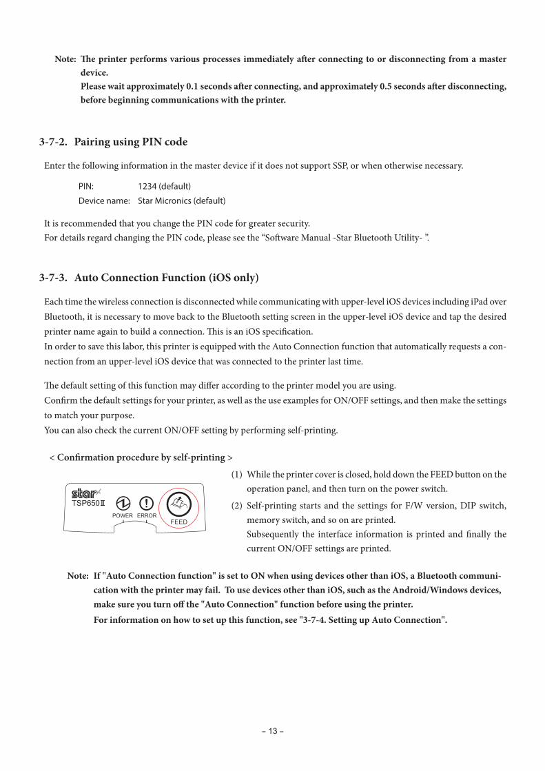
< Confirmation procedure by self-printing >
(1) While the printer cover is closed, hold down the FEED button on the operation panel, and then turn on the power switch.
(2) Self-printing starts and the settings for F/W version, DIP switch, memory switch, and so on are printed.
Subsequently the interface information is printed and finally the current ON/OFF settings are printed.
Note: If "Auto Connection function" is set to ON when using devices other than iOS, a Bluetooth communi-cation with the printer may fail. To use devices other than iOS, such as the Android/Windows devices, make sure you turn off the "Auto Connection" function before using the printer.
For information on how to set up this function, see "3-7-4. Setting up Auto Connection".

- 14 -
Auto Connection ON Auto Connection OFF
Reconnecting without changing the master device
After the printer is turned on, it automatically connects to the last master device that was connected.
After turning on the printer, tap this printer's name on the Blue-tooth settings screen on the mas-ter device.
Changing the connected master device
Disconnect the Bluetooth connec-tion in such a way as to turn OFF the power to the upper-level de-vice automatically connected.
Then, establish a pairing with a desired master device.
After turning on the printer, es-tablish a pairing with a desired master device.
Example (recommended) When connecting directly to the printer from one master device.
When using the printer with mul-tiple master device.
See the table below for details of Auto Connection setting.
- 15 -
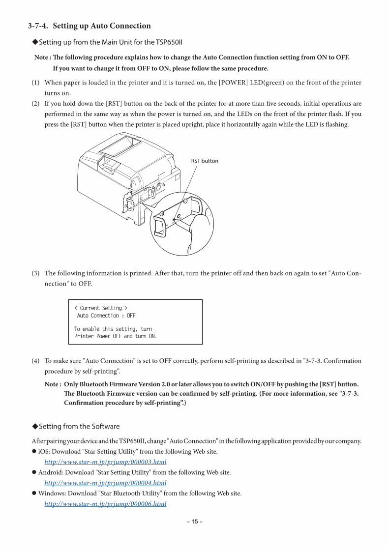
< Current Setting >Auto Connection : OFF
To enable this setting, turnPrinter Power OFF and turn ON.
PAIR
RST
PAIR
RST
RST button
3-7-4. Setting up Auto Connection
uSetting up from the Main Unit for the TSP650II
Note : The following procedure explains how to change the Auto Connection function setting from ON to OFF. If you want to change it from OFF to ON, please follow the same procedure.
(1) When paper is loaded in the printer and it is turned on, the [POWER] LED(green) on the front of the printer turns on.
(2) If you hold down the [RST] button on the back of the printer for at more than five seconds, initial operations are performed in the same way as when the power is turned on, and the LEDs on the front of the printer flash. If you press the [RST] button when the printer is placed upright, place it horizontally again while the LED is flashing.
(3) The following information is printed. After that, turn the printer off and then back on again to set "Auto Con-nection" to OFF.
(4) To make sure "Auto Connection" is set to OFF correctly, perform self-printing as described in "3-7-3. Confirmation procedure by self-printing”.
Note : Only Bluetooth Firmware Version 2.0 or later allows you to switch ON/OFF by pushing the [RST] button. The Bluetooth Firmware version can be confirmed by self-printing. (For more information, see "3-7-3. Confirmation procedure by self-printing”.)
uSetting from the Software
After pairing your device and the TSP650II, change "Auto Connection" in the following application provided by our company.l iOS: Download "Star Setting Utility" from the following Web site. http://www.star-m.jp/prjump/000003.htmll Android: Download "Star Setting Utility" from the following Web site. http://www.star-m.jp/prjump/000004.htmll Windows: Download "Star Bluetooth Utility" from the following Web site. http://www.star-m.jp/prjump/000006.html
- 16 -
PAIR
RST
PAIR
RST
RST button
Hold down for 4 seconds or more
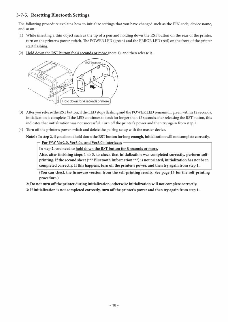
3-7-5. Resetting Bluetooth Settings
The following procedure explains how to initialize settings that you have changed such as the PIN code, device name, and so on.(1) While inserting a thin object such as the tip of a pen and holding down the RST button on the rear of the printer,
turn on the printer's power switch. The POWER LED (green) and the ERROR LED (red) on the front of the printer start flashing.
(2) Hold down the RST button for 4 seconds or more (note 1), and then release it.
(3) After you release the RST button, if the LED stops flashing and the POWER LED remains lit green within 12 seconds, initialization is complete. If the LED continues to flash for longer than 12 seconds after releasing the RST button, this indicates that initialization was not successful. Turn off the printer's power and then try again from step 1.
(4) Turn off the printer's power switch and delete the pairing setup with the master device.
Note 1: In step 2, if you do not hold down the RST button for long enough, initialization will not complete correctly. For F/W Ver2.0, Ver3.0a, and Ver3.0b interfaces
In step 2, you need to hold down the RST button for 8 seconds or more. Also, after finishing steps 1 to 3, to check that initialization was completed correctly, perform self-
printing. If the second sheet (*** Bluetooth Information ***) is not printed, initialization has not been completed correctly. If this happens, turn off the printer's power, and then try again from step 1.
(You can check the firmware version from the self-printing results. See page 13 for the self-printing procedure.)
2: Do not turn off the printer during initialization; otherwise initialization will not complete correctly. 3: If initialization is not completed correctly, turn off the printer's power and then try again from step 1.
- 17 -
Caution Symbol
These symbols are located near the thermal print head.Because the thermal print head is hot immediately after printing, do not touch it. Static electricity can damage the thermal print head. To protect the thermal print head from static electricity, do not touch it.
This symbol is located near the cutter. Never touch the cutter blade, as you could injure your fingers.
This symbol is located near the peripheral drive connector.Do not connect this to a telephone.
This symbol is located near the screws securing the case or the protective plate, which should not be opened by individuals other than service personnel. Individuals, other than service personnel, should not remove these screws. High voltage areas in the case can be dangerous.
WARNINGl If you notice smoke or strange odors coming from this product, turn the power switch off immediately, and remove
the power cord from the AC outlet. For repairs, contact the dealer that you bought the product from.
l Never attempt to repair the product yourself. Doing so can be dangerous.
l Never disassemble or modify the product. Doing so may result in injury, fire, or electric shock.
l On models that have cutters or tear bars, do not touch the cutter blade or the tear bar.
- There is a cutter or tear bar inside the paper outlet slot. Never put your hand in the slot regardless of whether or not the printer is in operation.
- You must open the printer cover to replace paper. However, because the cutter blade or tear bar is located inside of the cover, be careful not to bring your face and hands too close to the blade or tear bar when the cover is open.
l During and immediately after printing, the area around the print head is very hot. Don’t touch it because you could be burned.
l Be sure to turn off the printer before performing maintenance on the cutter. Failing to do so is dangerous.
CAUTIONl We recommend that you unplug the printer from the power outlet whenever you do not plan to use the printer for
long periods. Because of this, you should locate the printer so that the power outlet it is plugged into is nearby and easy to access.
l If an AC cord set is supplied with the product, the power cord that is included has been specially designed for the product.
l Make sure that the printer and the PC are turned off and unplugged from their AC outlets before you make connec-tions.
l Do not connect a telephone line to the peripheral drive connector, which is used for devices such as cash drawers. Doing so may cause the printer to malfunction. Also, for safety purposes, do not connect a wire that may carry ex-cessive voltage to the peripheral drive connector.
3-8. Setup Precautions
- 18 -
l Do not open the printer covers while the printer is printing or cutting.
l Do not pull out paper when the printer cover is closed.
l If liquid or foreign objects (such as coins and paper) enter the inside of the printer, turn the power switch off, disconnect the power cord from the AC outlet, and consult the dealer that you bought the product from. Continuing to use the printer may lead to a short-circuit, which may cause electric shock or fire.
l The heating element and the driver IC of the thermal print head are easily damaged. Do not touch them with metal objects, sandpaper, etc.
l Do not touch the thermal print head heating element. Doing so may make it dirty, which will decrease the printing quality.
l Static electricity can damage the driver IC and other components of the thermal print head. Avoid touching it di-rectly.
l Do not operate the printer if there is moisture (which has been caused by condensation or another factor) on the front surface of the head.
l The printing quality and the thermal print head’s service life cannot be guaranteed if paper other than the recom-mended paper is used.
In particular, thermal paper containing Na+, K+, or C1- may drastically reduce the service life of the thermal print head. We recommend that you use paper with the following maximum ion densities: 500 ppm of Na+, 150 ppm of K+, and 300 ppm of Cl-.
For details on recommended thermal paper, see the following webpage. http://www.starmicronics.com/support/
CAUTIONWireless Communication
l Do not use the device where using wireless devices is prohibited or may cause interference or danger.
l The radio waves generated by the device may interfere with the operation of electronic medical devices. If you are using any electrical medical device, contact its manufacturer for the restrictions on the use of the device.
l Security functionality for Bluetooth is installed in this product. Configure the security settings according to the manual (available on the Star Micronics website) to reduce the risk of security issues.
l This device supports Bluetooth.
Since this functionality may be limited by local regulations, first review the radio laws specific to the country in which the product will be used.
l Below is a list of laws this device has been approved by. As Star Micronics is committed to constant innovation, revi-sions may be made without an announcement. Access the Star Micronics website for the latest listing of approvals.
l Please refer to Star Micronics website for the latest information and manuals.

- 19 -
2~3mm
4. Attaching the Accessories
The following accessories are necessary when mounting the printer to a wall.• Holder plate and two flangeless screws
The following accessories are necessary when positioning the printer vertically.• Four rubber feet
The following accessories do not necessarily have to be attached. Attach it if necessary.• Switch cover
4-1. Attaching the Holder Plate
<Precoutions>n The holder plate is attached to the printer using the included screws and is hooked onto screws that are installed
into the wall.n The screws on the wall are not included. Use commercially available screws (4 mm diameter) that are suitable for the wall material (wood, steel beam,
concrete, etc.).n The printer’s weight is approximately 2.4 kg when the largest diameter roll paper is loaded. Use screws on the wall that have both shear strength and pulling-out strength to withstand a force of at least
12 kgf (118 N).
(1) Attach the holding plate to the printer. Then tighten the two screws that were supplied to secure it in place.
(2) Position the printer over the screws, etc., on the wall and then slide it downward to set it in place. After setting the printer in place, check the screws on the wall again to make sure that they are able to support the
printer’s weight.
- 20 -
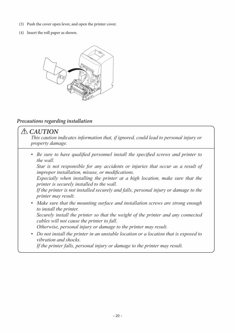
(3) Push the cover open lever, and open the printer cover.
(4) Insert the roll paper as shown.
Precautions regarding installation
CAUTIONThis caution indicates information that, if ignored, could lead to personal injury or property damage.
• Be sure tohavequalifiedpersonnel install the specified screwsandprinter tothewall.
Star is not responsible for any accidents or injuries that occur as a result of improperinstallation,misuse,ormodifications.
Especially when installing the printer at a high location, make sure that theprinterissecurelyinstalledtothewall.
If the printer is not installed securely and falls, personal injury or damage to the printer may result.
• Makesurethatthemountingsurfaceandinstallationscrewsarestrongenoughto install the printer.
Securelyinstalltheprintersothattheweightoftheprinterandanyconnectedcableswillnotcausetheprintertofall.
Otherwise,personalinjuryordamagetotheprintermayresult.• Do not install the printer in an unstable location or a location that is exposed to
vibration and shocks. If the printer falls, personal injury or damage to the printer may result.
- 21 -
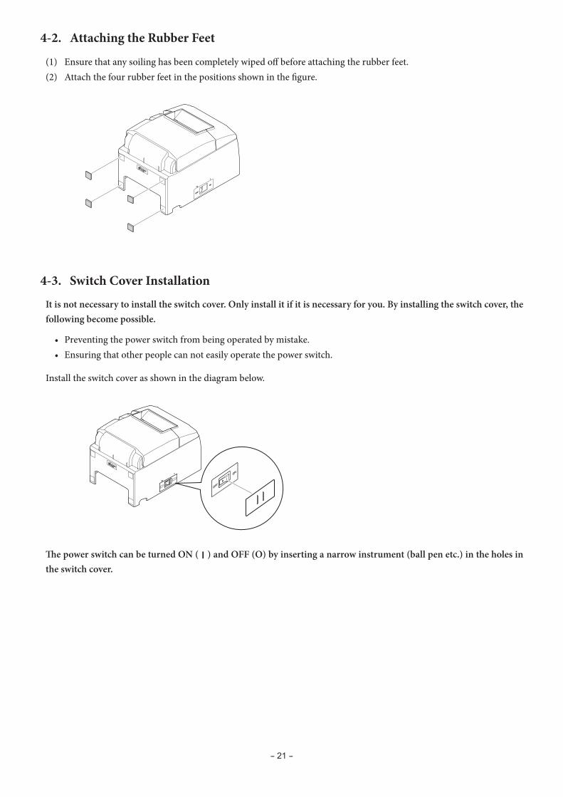
4-2. Attaching the Rubber Feet
(1) Ensure that any soiling has been completely wiped off before attaching the rubber feet.(2) Attach the four rubber feet in the positions shown in the figure.
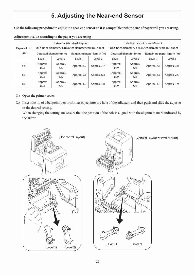
4-3. Switch Cover Installation
It is not necessary to install the switch cover. Only install it if it is necessary for you. By installing the switch cover, the following become possible.
• Preventing the power switch from being operated by mistake. • Ensuring that other people can not easily operate the power switch.
Install the switch cover as shown in the diagram below.
The power switch can be turned ON ( | ) and OFF (O) by inserting a narrow instrument (ball pen etc.) in the holes in the switch cover.
- 22 -
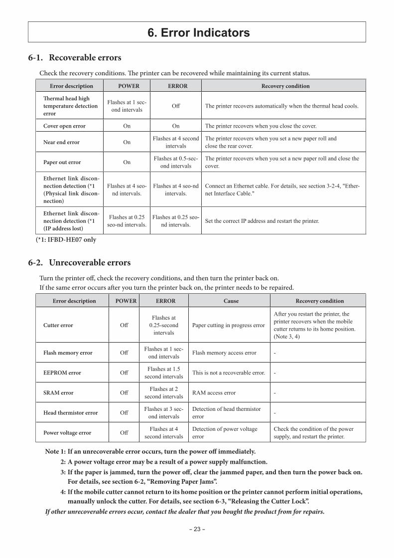
5. Adjusting the Near-end Sensor
Use the following procedure to adjust the near-end sensor so it is compatible with the size of paper roll you are using.
Adjustment value according to the paper you are using
Paper Width
(μm)
Horizontal (standard) Layout
ø12 inner diameter / ø18 outer diameter core roll paper
Vertical Layout or Wall-Mount
ø12 inner diameter / ø18 outer diameter core roll paper
Detected diameter (mm) Remaining paper length (m) Detected diameter (mm) Remaining paper length (m)
Level 1 Level 2 Level 1 Level 2 Level 1 Level 2 Level 1 Level 2
53Approx.
ø23Approx.
ø29Approx. 3.0 Approx. 7.7
Approx. ø29
Approx. ø23
Approx. 7.7 Approx. 3.0
65Approx.
ø23Approx.
ø29Approx. 2.5 Approx. 6.3
Approx. ø29
Approx. ø23
Approx. 6.3 Approx. 2.5
85Approx.
ø23Approx.
ø29Approx. 1.9 Approx. 4.8
Approx. ø29
Approx. ø23
Approx. 4.8 Approx. 1.9
(1) Open the printer cover.
(2) Insert the tip of a ballpoint pen or similar object into the hole of the adjuster, and then push and slide the adjuster to the desired setting.
When changing the setting, make sure that the position of the hole is aligned with the alignment mark indicated by the arrow.
[Horizontal Layout] [Vertical Layout or Wall-Mount]
(Level 1) (Level 2) (Level 1) (Level 2)
- 23 -
6. Error Indicators
6-1. Recoverable errorsCheck the recovery conditions. The printer can be recovered while maintaining its current status.
Error description POWER ERROR Recovery condition
Thermal head high temperature detection error
Flashes at 1 sec-ond intervals Off The printer recovers automatically when the thermal head cools.
Cover open error On On The printer recovers when you close the cover.
Near end error On Flashes at 4 second intervals
The printer recovers when you set a new paper roll andclose the rear cover.
Paper out error On Flashes at 0.5-sec-ond intervals
The printer recovers when you set a new paper roll and close the cover.
Ethernet link discon-nection detection (*1(Physical link discon-nection)
Flashes at 4 seo-nd intervals.
Flashes at 4 seo-nd intervals.
Connect an Ethernet cable. For details, see section 3-2-4, "Ether-net Interface Cable."
Ethernet link discon-nection detection (*1(IP address lost)
Flashes at 0.25 seo-nd intervals.
Flashes at 0.25 seo-nd intervals. Set the correct IP address and restart the printer.
(*1: IFBD-HE07 only
6-2. Unrecoverable errorsTurn the printer off, check the recovery conditions, and then turn the printer back on. If the same error occurs after you turn the printer back on, the printer needs to be repaired.
Error description POWER ERROR Cause Recovery condition
Cutter error OffFlashes at
0.25-second intervals
Paper cutting in progress error
After you restart the printer, the printer recovers when the mobile cutter returns to its home position. (Note 3, 4)
Flash memory error Off Flashes at 1 sec-ond intervals Flash memory access error -
EEPROM error Off Flashes at 1.5 second intervals This is not a recoverable error. -
SRAM error Off Flashes at 2 second intervals RAM access error -
Head thermistor error Off Flashes at 3 sec-ond intervals
Detection of head thermistor error -
Power voltage error Off Flashes at 4 second intervals
Detection of power voltage error
Check the condition of the power supply, and restart the printer.
Note 1: If an unrecoverable error occurs, turn the power off immediately. 2: A power voltage error may be a result of a power supply malfunction. 3: If the paper is jammed, turn the power off, clear the jammed paper, and then turn the power back on.
For details, see section 6-2, “Removing Paper Jams”. 4: If the mobile cutter cannot return to its home position or the printer cannot perform initial operations,
manually unlock the cutter. For details, see section 6-3, “Releasing the Cutter Lock”.If other unrecoverable errors occur, contact the dealer that you bought the product from for repairs.
- 24 -
7. Preventing and Removing Paper Jams
Thermal head
7-1. Preventing Paper Jamsl To avoid paper jams and other problems, feed the paper at least 1 mm (8 dot lines) before printing.l If you want to use the cutter, to avoid paper jams and other problems, we recommend a margin of at least 5 mm
from the end of the printed area to the cutting position.l When you set the paper roll into the printer, do not pull out the end of the paper at an angle.l Do not touch the paper roll when the printer is printing or feeding paper or before the cut operation has finished
completely.l Holding or pulling the paper while it is being fed may cause paper jams, improper cutting, or improper line breaks.l Do not remove the paper while it is being cut. This can cause a paper jam.
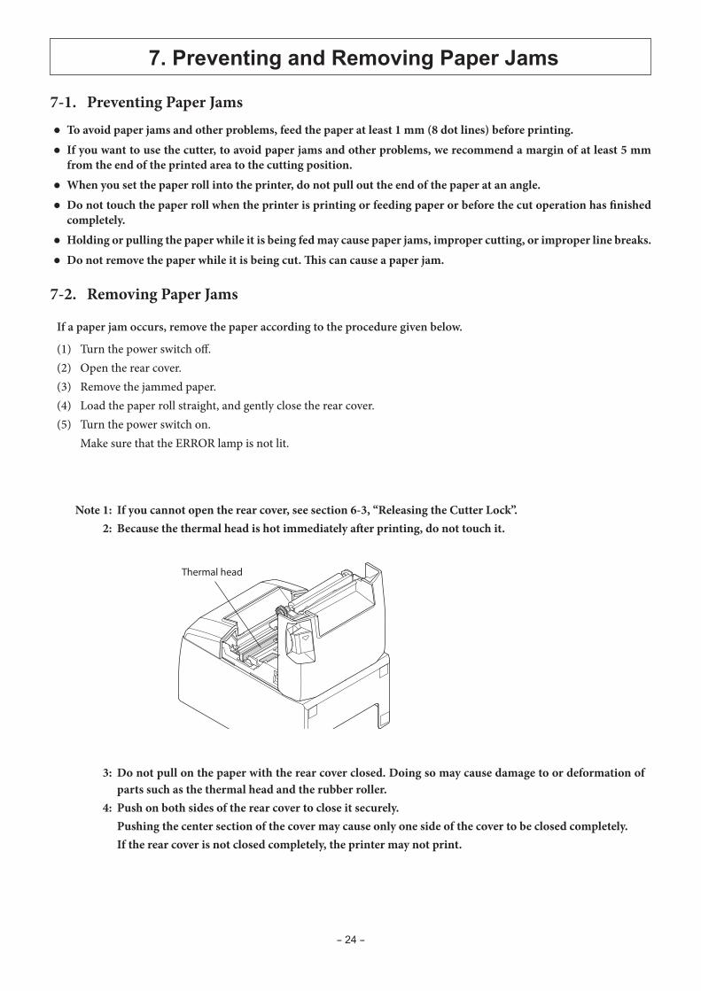
7-2. Removing Paper Jams
If a paper jam occurs, remove the paper according to the procedure given below.
(1) Turn the power switch off.(2) Open the rear cover.(3) Remove the jammed paper.(4) Load the paper roll straight, and gently close the rear cover.(5) Turn the power switch on. Make sure that the ERROR lamp is not lit.
Note 1: If you cannot open the rear cover, see section 6-3, “Releasing the Cutter Lock”. 2: Because the thermal head is hot immediately after printing, do not touch it.
3: Do not pull on the paper with the rear cover closed. Doing so may cause damage to or deformation of parts such as the thermal head and the rubber roller.
4: Push on both sides of the rear cover to close it securely. Pushing the center section of the cover may cause only one side of the cover to be closed completely. If the rear cover is not closed completely, the printer may not print.
- 25 -
Home position
Knob
Drive knife
Drive knife
NG
OK
Home position
Front cover
Cutter unit
Printer cover
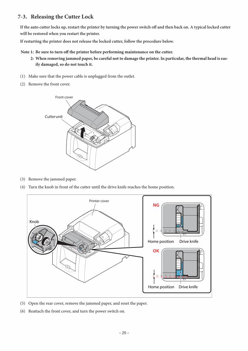
7-3. Releasing the Cutter Lock
If the auto cutter locks up, restart the printer by turning the power switch off and then back on. A typical locked cutter will be restored when you restart the printer.
If restarting the printer does not release the locked cutter, follow the procedure below.
Note 1: Be sure to turn off the printer before performing maintenance on the cutter. 2: When removing jammed paper, be careful not to damage the printer. In particular, the thermal head is eas-
ily damaged, so do not touch it.
(1) Make sure that the power cable is unplugged from the outlet.
(2) Remove the front cover.
(3) Remove the jammed paper.
(4) Turn the knob in front of the cutter until the drive knife reaches the home position.
(5) Open the rear cover, remove the jammed paper, and reset the paper.
(6) Reattach the front cover, and turn the power switch on.
- 26 -
8. Maintenance
Thermal head
Rubber roller
Paper holder
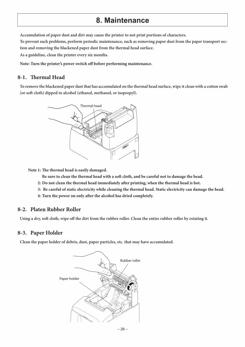
Accumulation of paper dust and dirt may cause the printer to not print portions of characters.To prevent such problems, perform periodic maintenance, such as removing paper dust from the paper transport sec-tion and removing the blackened paper dust from the thermal head surface.As a guideline, clean the printer every six months.
Note: Turn the printer’s power switch off before performing maintenance.
8-1. Thermal HeadTo remove the blackened paper dust that has accumulated on the thermal head surface, wipe it clean with a cotton swab (or soft cloth) dipped in alcohol (ethanol, methanol, or isopropyl).
8-2. Platen Rubber RollerUsing a dry, soft cloth, wipe off the dirt from the rubber roller. Clean the entire rubber roller by rotating it.
8-3. Paper HolderClean the paper holder of debris, dust, paper particles, etc. that may have accumulated.
Note 1: The thermal head is easily damaged. Be sure to clean the thermal head with a soft cloth, and be careful not to damage the head. 2: Do not clean the thermal head immediately after printing, when the thermal head is hot. 3: Be careful of static electricity while cleaning the thermal head. Static electricity can damage the head. 4: Turn the power on only after the alcohol has dried completely.