Thermal Modeling and Model Correlation of the LORRI Telescope · PDF fileThermal Modeling and...
36
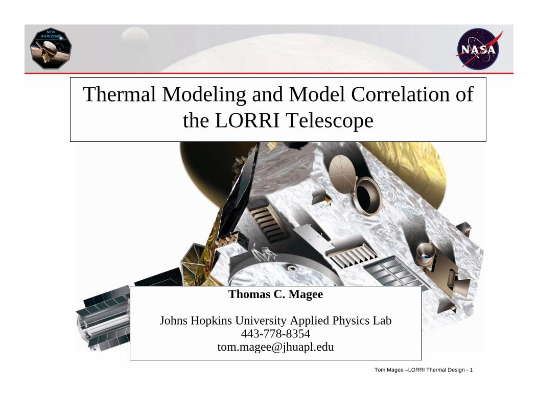
Tom Magee –LORRI Thermal Design - 1 Thermal Modeling and Model Correlation of the LORRI Telescope Thomas C. Magee Johns Hopkins University Applied Physics Lab 443-778-8354 [email protected]
Transcript of Thermal Modeling and Model Correlation of the LORRI Telescope · PDF fileThermal Modeling and...
Tom Magee –LORRI Thermal Design - 1
Thermal Modeling and Model Correlation of the LORRI Telescope
Thomas C. Magee
Johns Hopkins University Applied Physics Lab443-778-8354
Tom Magee –LORRI Thermal Design - 2
Introduction
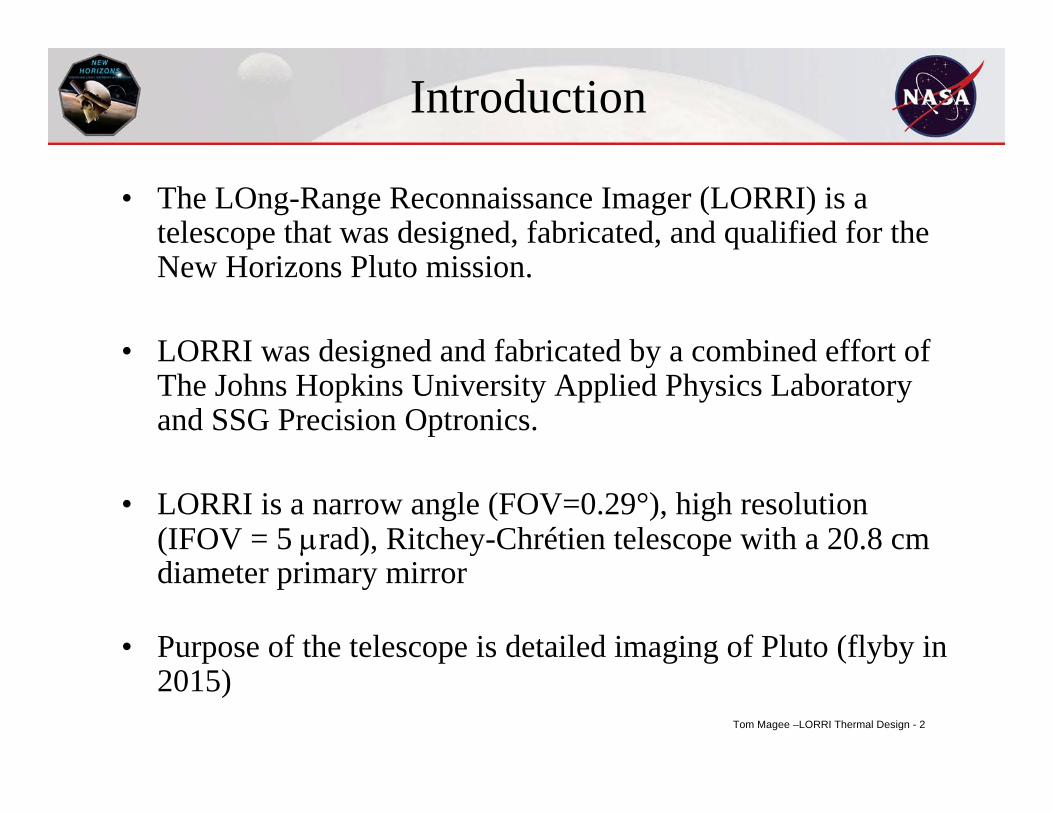
• The LOng-Range Reconnaissance Imager (LORRI) is a telescope that was designed, fabricated, and qualified for the New Horizons Pluto mission.
• LORRI was designed and fabricated by a combined effort of The Johns Hopkins University Applied Physics Laboratory and SSG Precision Optronics.
• LORRI is a narrow angle (FOV=0.29°), high resolution (IFOV = 5 µrad), Ritchey-Chrétien telescope with a 20.8 cm diameter primary mirror
• Purpose of the telescope is detailed imaging of Pluto (flyby in 2015)
Tom Magee –LORRI Thermal Design - 3
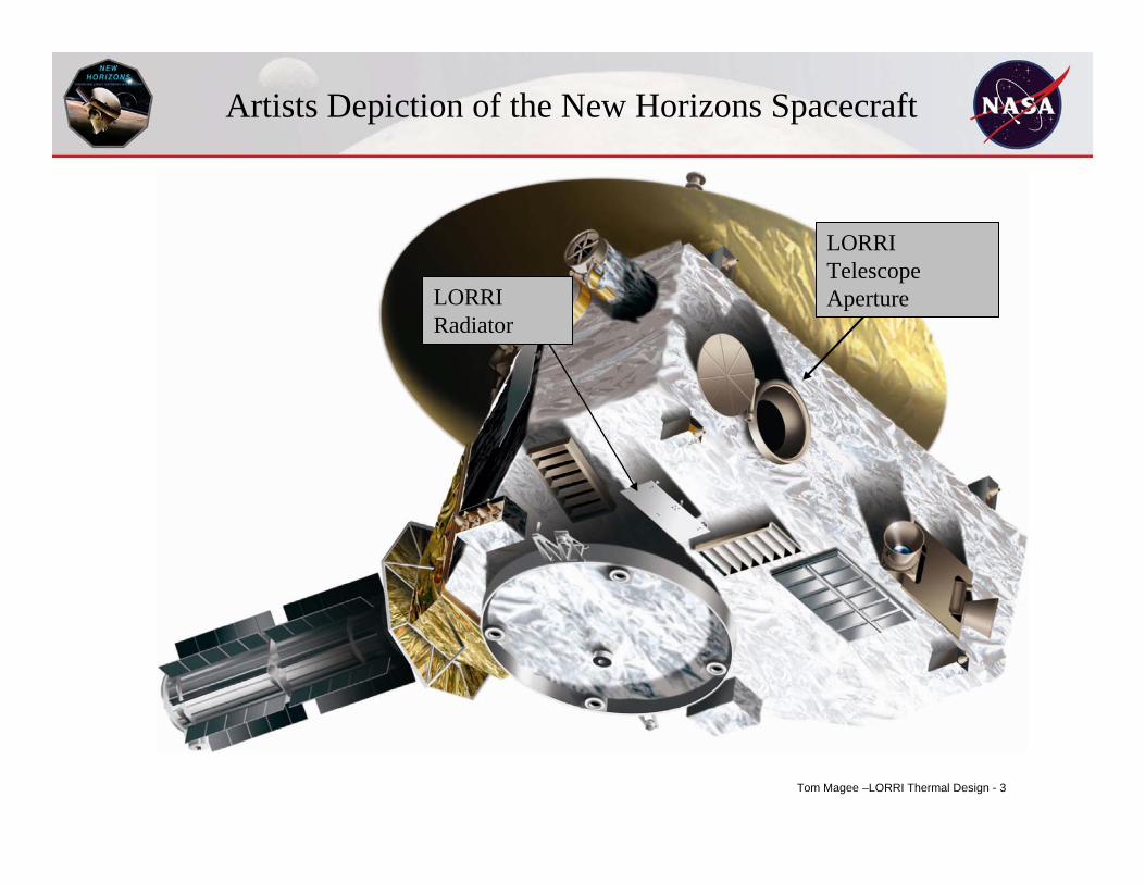
LORRI Radiator
LORRI Telescope Aperture
Artists Depiction of the New Horizons Spacecraft
Tom Magee –LORRI Thermal Design - 4
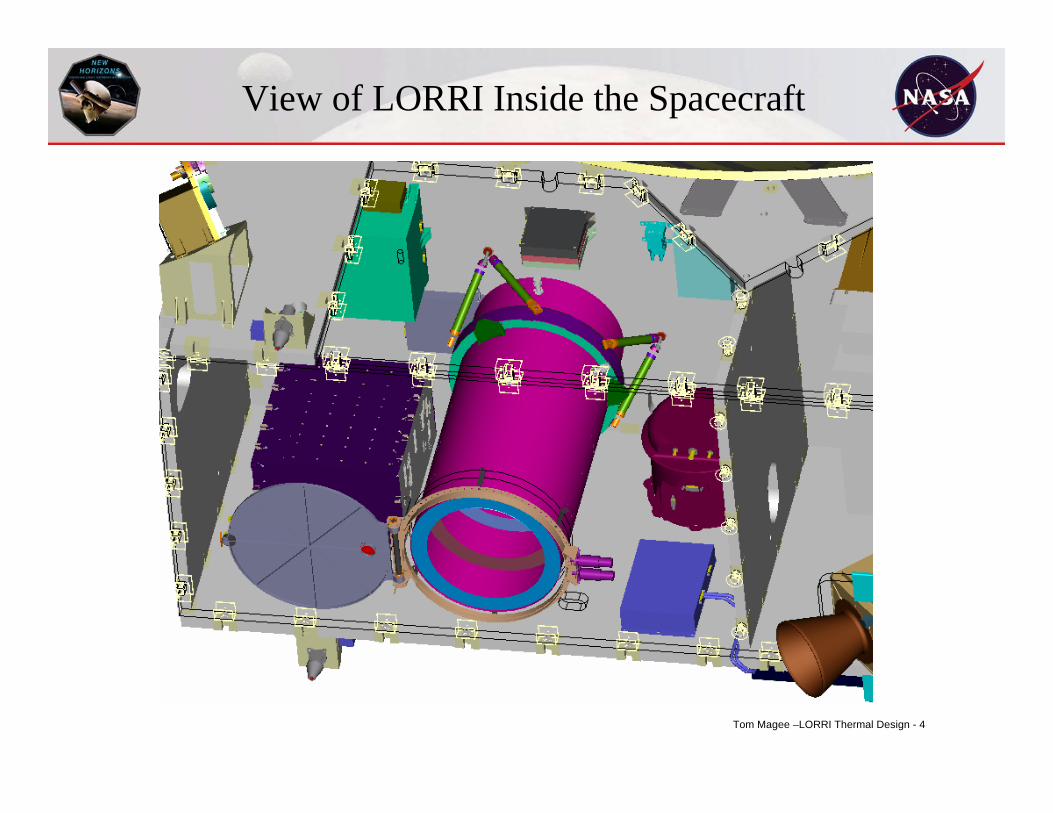
View of LORRI Inside the Spacecraft
Tom Magee –LORRI Thermal Design - 5
Thermal Challenges
• Maintain focus without a focusing mechanism over a wide temperature range (-125ºC to 40ºC)– gradient from M1 to M2 must be less than 2.5ºC– requires a low CTE material with high thermal
conductivity
• Maintain the CCD temperature below -70ºC while mounted deep inside a spacecraft which is at +40ºC– requires good thermal isolation
Tom Magee –LORRI Thermal Design - 6
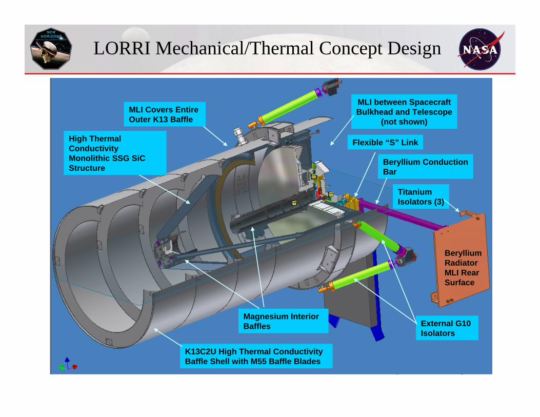
LORRI Mechanical/Thermal Concept Design
Magnesium Interior Baffles
K13C2U High Thermal Conductivity Baffle Shell with M55 Baffle Blades
External G10 Isolators
Flexible “S” Link
Beryllium ConductionBar
BerylliumRadiatorMLI RearSurface
TitaniumIsolators (3)
MLI between SpacecraftBulkhead and Telescope
(not shown)
High Thermal Conductivity Monolithic SSG SiC Structure
MLI Covers Entire Outer K13 Baffle
Tom Magee –LORRI Thermal Design - 7
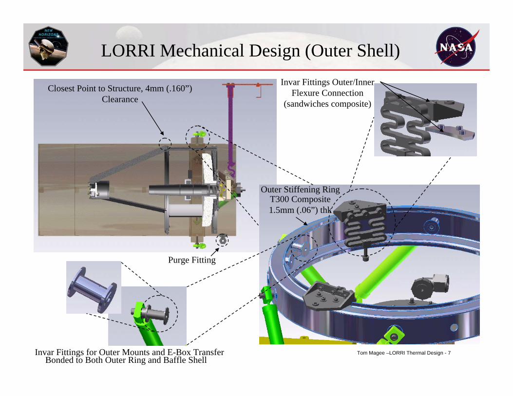
LORRI Mechanical Design (Outer Shell)
Closest Point to Structure, 4mm (.160”) Clearance
Purge Fitting
Outer Stiffening Ring
Invar Fittings for Outer Mounts and E-Box TransferBonded to Both Outer Ring and Baffle Shell
T300 Composite 1.5mm (.06”) thk
Invar Fittings Outer/Inner Flexure Connection
(sandwiches composite)
Tom Magee –LORRI Thermal Design - 8
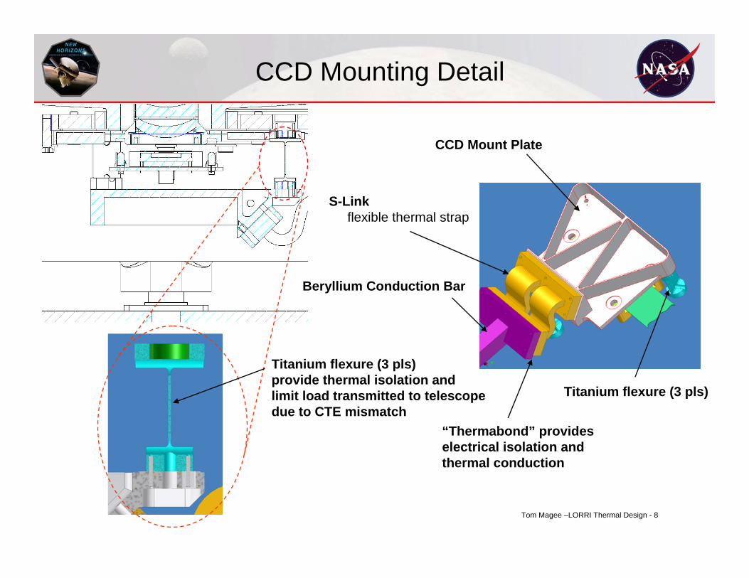
CCD Mounting Detail
Titanium flexure (3 pls)provide thermal isolation andlimit load transmitted to telescopedue to CTE mismatch
CCD Mount Plate
Beryllium Conduction Bar
“Thermabond” provides electrical isolation and thermal conduction
Titanium flexure (3 pls)
S-Linkflexible thermal strap
Tom Magee –LORRI Thermal Design - 9
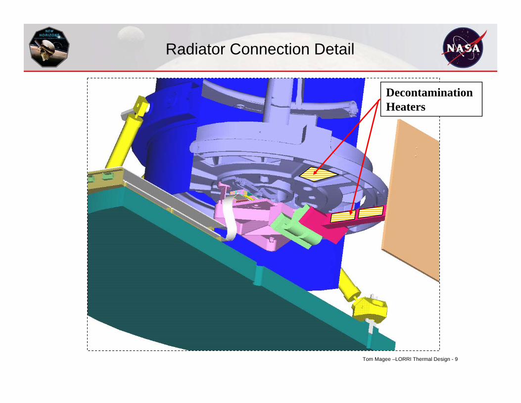
Radiator Connection Detail
Decontamination Heaters
Tom Magee –LORRI Thermal Design - 10
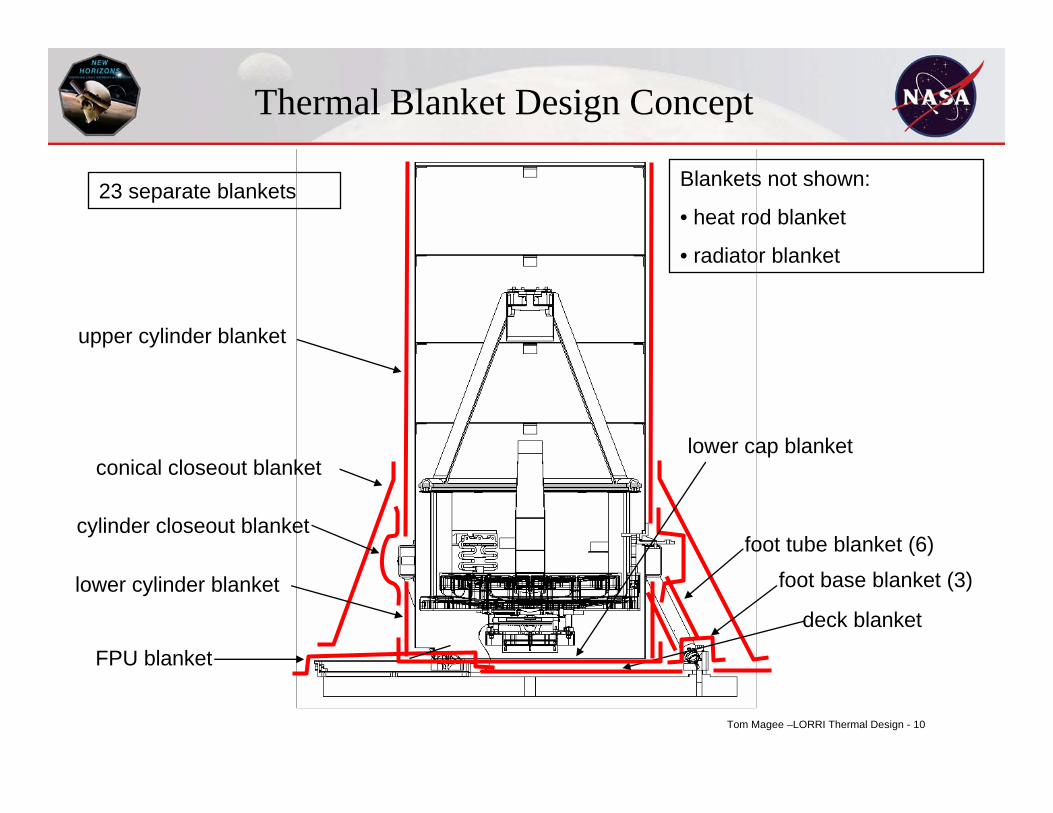
Thermal Blanket Design Concept
upper cylinder blanket
lower cylinder blanketdeck blanket
FPU blanket
foot base blanket (3)
lower cap blanket
Blankets not shown:
• heat rod blanket
• radiator blanket
cylinder closeout blanket
conical closeout blanket
foot tube blanket (6)
23 separate blankets
Tom Magee –LORRI Thermal Design - 11
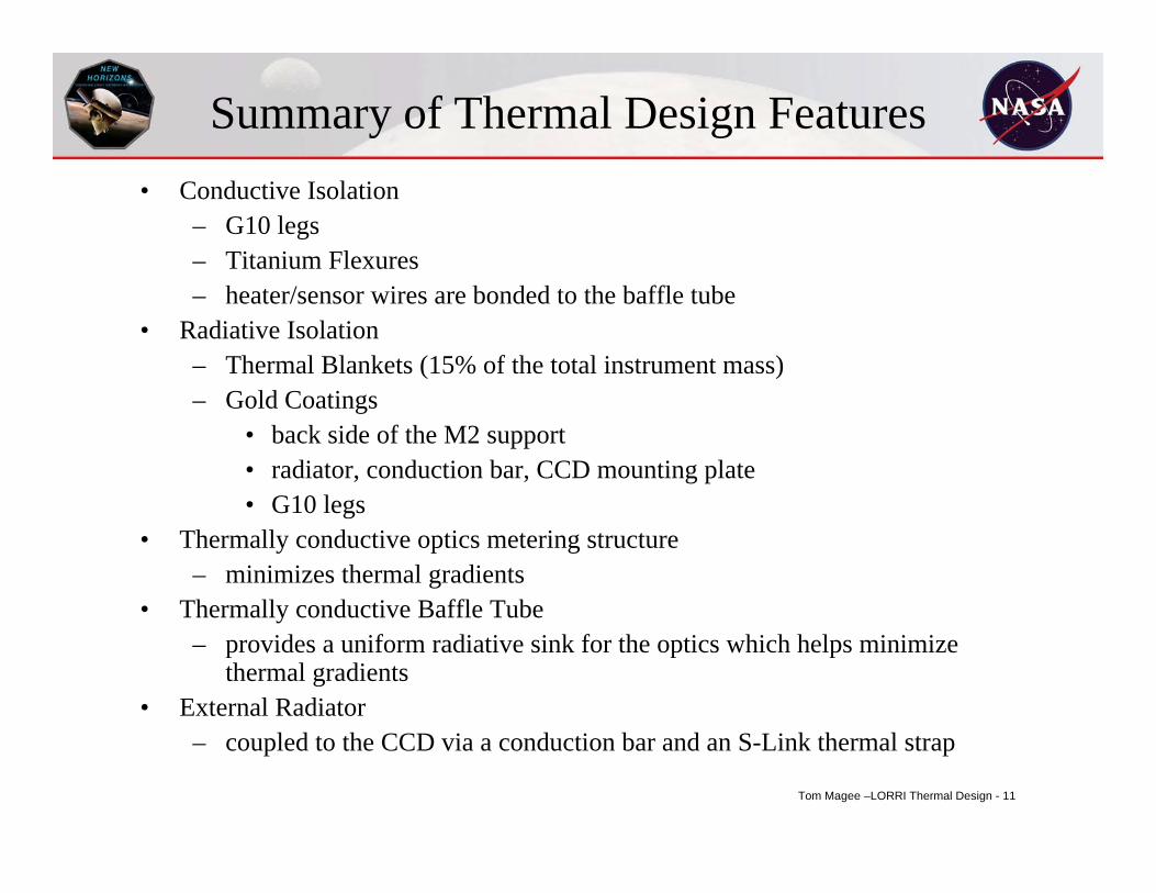
Summary of Thermal Design Features• Conductive Isolation
– G10 legs– Titanium Flexures– heater/sensor wires are bonded to the baffle tube
• Radiative Isolation– Thermal Blankets (15% of the total instrument mass)– Gold Coatings
• back side of the M2 support• radiator, conduction bar, CCD mounting plate• G10 legs
• Thermally conductive optics metering structure– minimizes thermal gradients
• Thermally conductive Baffle Tube– provides a uniform radiative sink for the optics which helps minimize
thermal gradients• External Radiator
– coupled to the CCD via a conduction bar and an S-Link thermal strap
Tom Magee –LORRI Thermal Design - 12
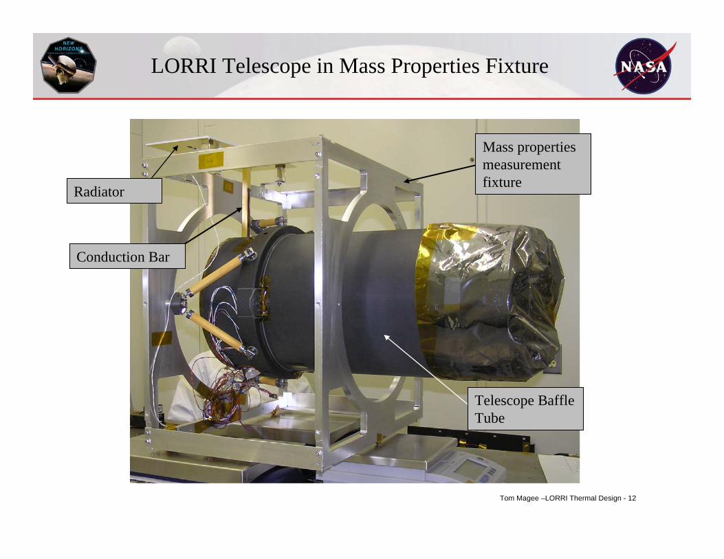
Mass properties measurement fixtureRadiator
Conduction Bar
Telescope Baffle Tube
LORRI Telescope in Mass Properties Fixture
Tom Magee –LORRI Thermal Design - 13
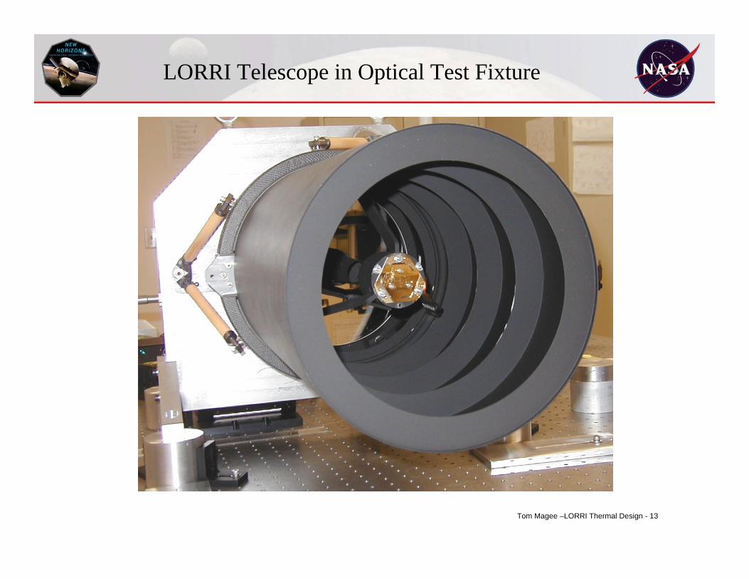
LORRI Telescope in Optical Test Fixture
Tom Magee –LORRI Thermal Design - 14
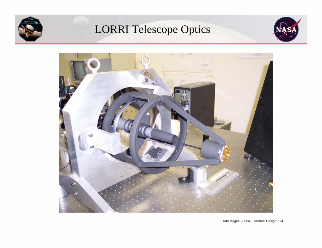
LORRI Telescope Optics
Tom Magee –LORRI Thermal Design - 15
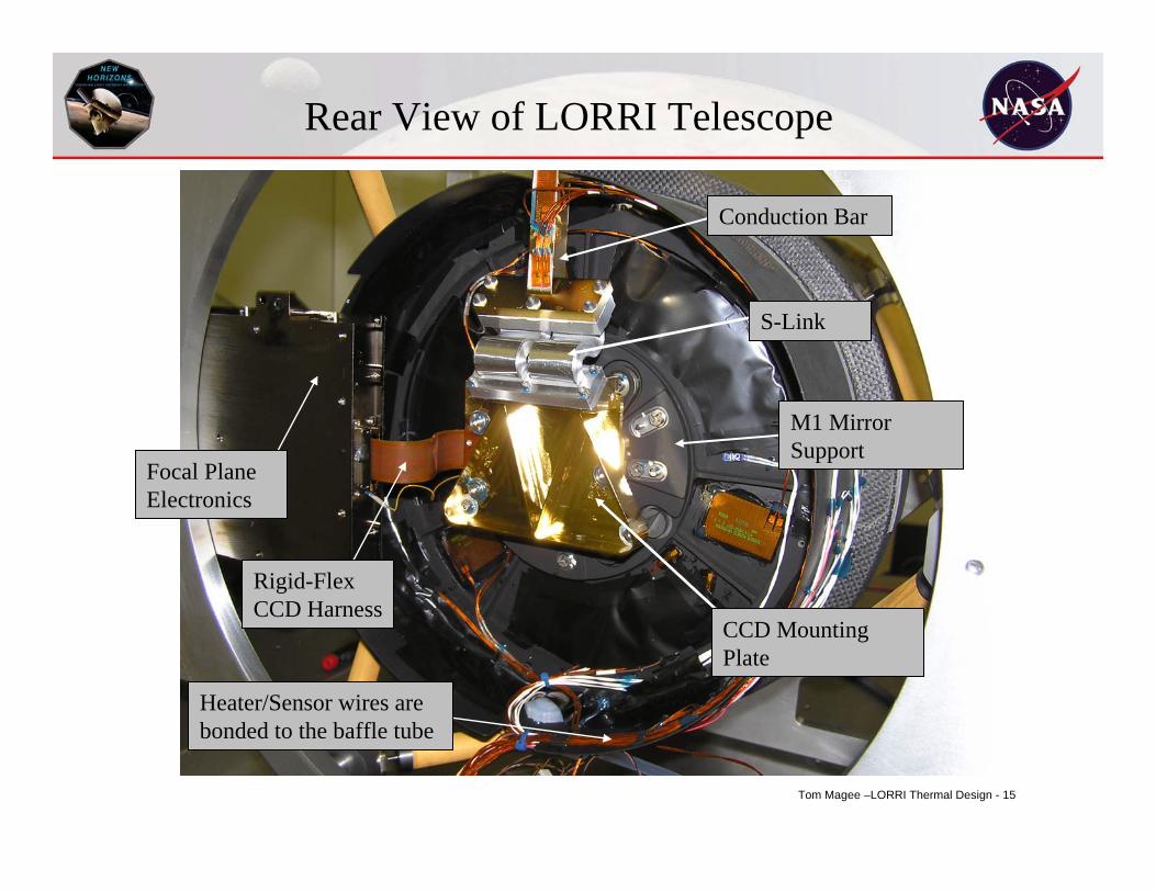
Focal Plane Electronics
Conduction Bar
CCD Mounting Plate
Rear View of LORRI Telescope
S-Link
M1 Mirror Support
Rigid-Flex CCD Harness
Heater/Sensor wires are bonded to the baffle tube
Tom Magee –LORRI Thermal Design - 16
Thermal Analysis Techniques
• Finite Difference model is required– hand calculations using lump masses and conductors
• finite element techniques create too many nodes to be compatiblewith ray trace modeling
– execution in TAK (SINDA)
• Radiation view factors are calculated between surfaces using a ray-tracing technique (TSS software)
• FEA techniques were used to support the finite difference model for complex structures
Tom Magee –LORRI Thermal Design - 17
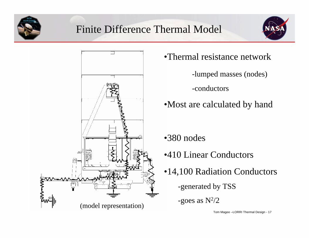
Finite Difference Thermal Model
•Thermal resistance network
-lumped masses (nodes)
-conductors
•Most are calculated by hand
•380 nodes
•410 Linear Conductors
•14,100 Radiation Conductors-generated by TSS
-goes as N2/2(model representation)
Tom Magee –LORRI Thermal Design - 18
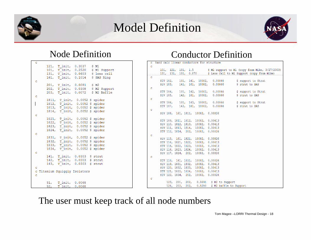
Model Definition
Node Definition Conductor Definition
The user must keep track of all node numbers
Tom Magee –LORRI Thermal Design - 19
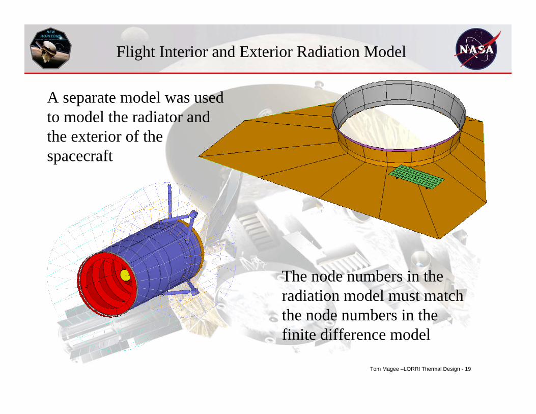
Flight Interior and Exterior Radiation Model
A separate model was used to model the radiator and the exterior of the spacecraft
The node numbers in the radiation model must match the node numbers in the finite difference model
Tom Magee –LORRI Thermal Design - 20
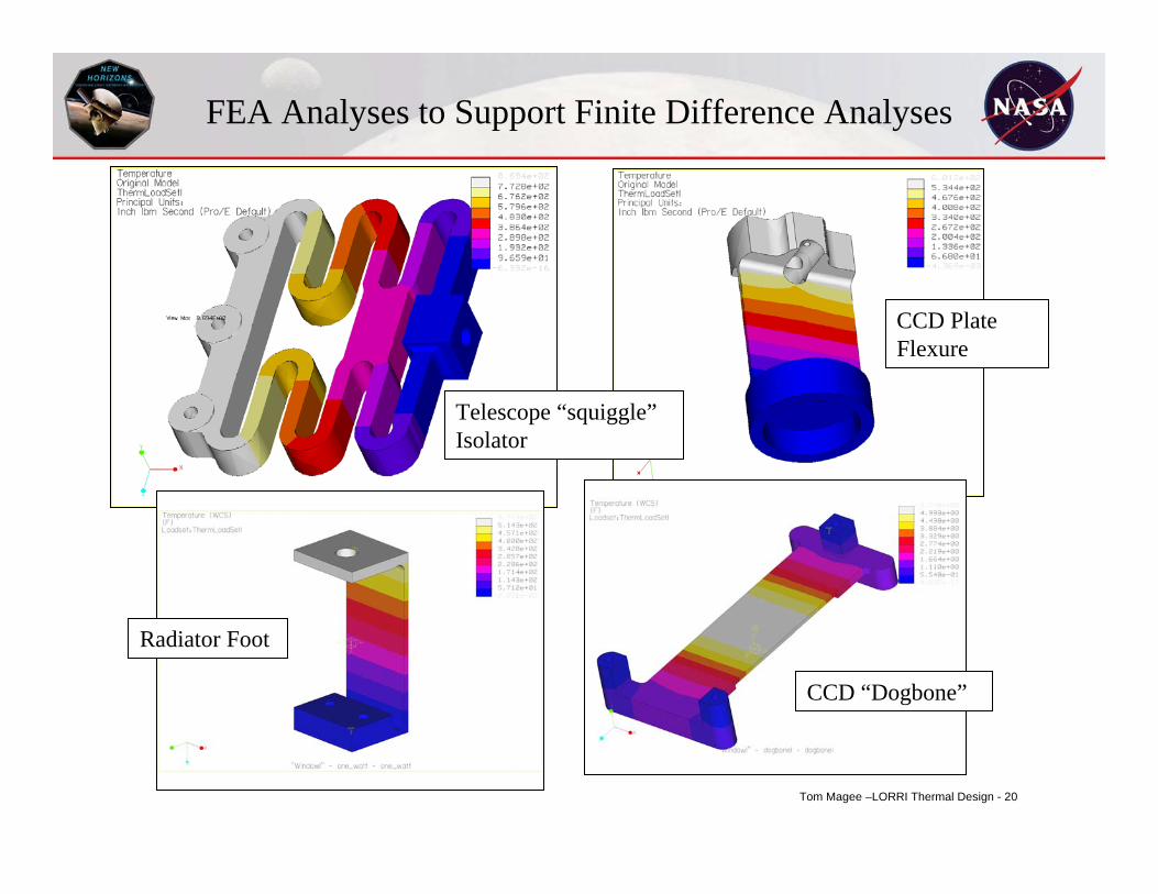
FEA Analyses to Support Finite Difference Analyses
CCD “Dogbone”
CCD Plate Flexure
Telescope “squiggle” Isolator
Radiator Foot
Tom Magee –LORRI Thermal Design - 21
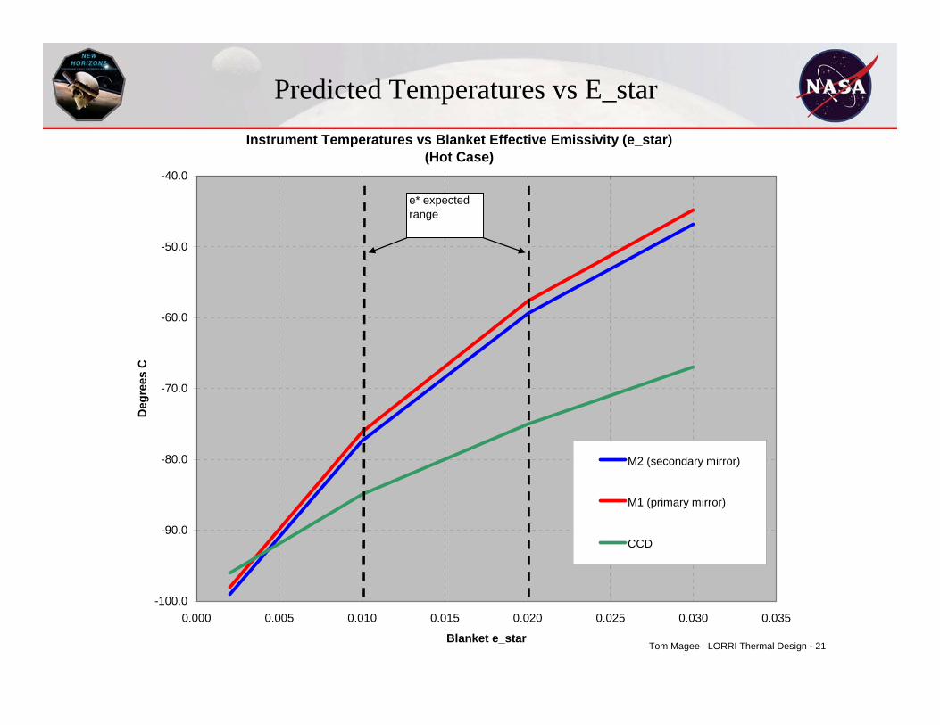
Predicted Temperatures vs E_starInstrument Temperatures vs Blanket Effective Emissivity (e_star)
(Hot Case)
-100.0
-90.0
-80.0
-70.0
-60.0
-50.0
-40.0
0.000 0.005 0.010 0.015 0.020 0.025 0.030 0.035
Blanket e_star
Deg
rees
C
M2 (secondary mirror)
M1 (primary mirror)
CCD
e* expected range
Tom Magee –LORRI Thermal Design - 22
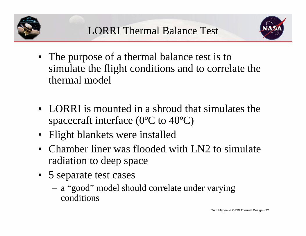
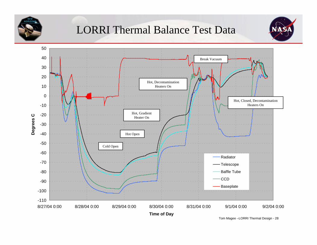
LORRI Thermal Balance Test
• The purpose of a thermal balance test is to simulate the flight conditions and to correlate the thermal model
• LORRI is mounted in a shroud that simulates the spacecraft interface (0ºC to 40ºC)
• Flight blankets were installed• Chamber liner was flooded with LN2 to simulate
radiation to deep space• 5 separate test cases
– a “good” model should correlate under varying conditions
Tom Magee –LORRI Thermal Design - 23
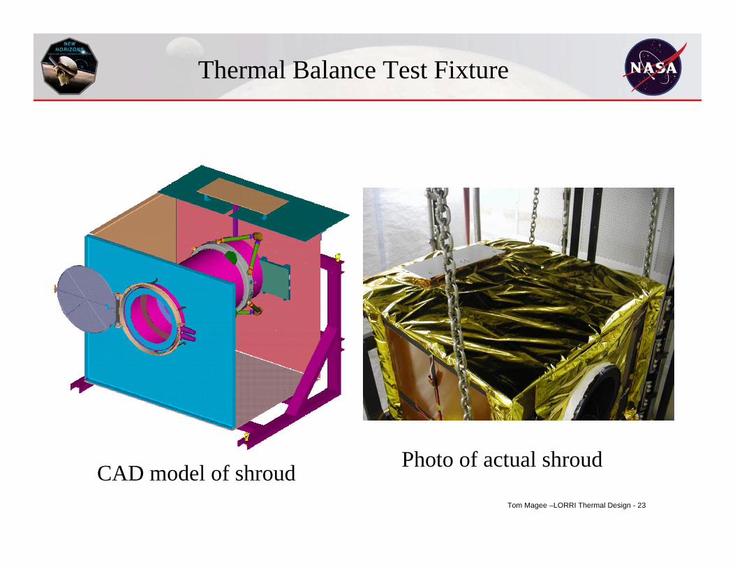
Thermal Balance Test Fixture
CAD model of shroud Photo of actual shroud
Tom Magee –LORRI Thermal Design - 24
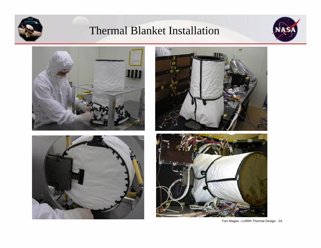
Thermal Blanket Installation
Tom Magee –LORRI Thermal Design - 25
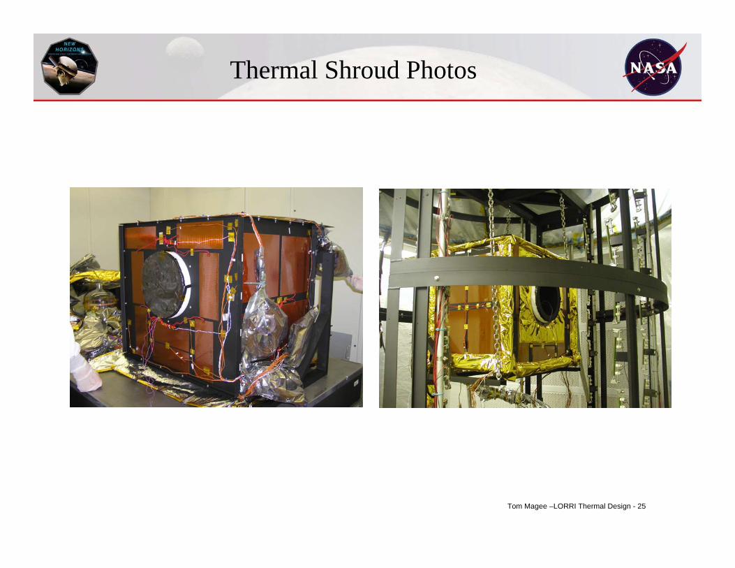
Thermal Shroud Photos
Tom Magee –LORRI Thermal Design - 26
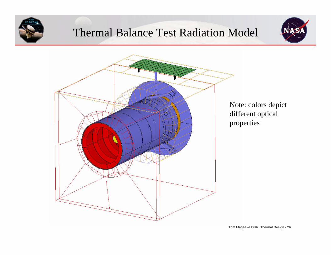
Thermal Balance Test Radiation Model
Note: colors depict different optical properties
Tom Magee –LORRI Thermal Design - 27
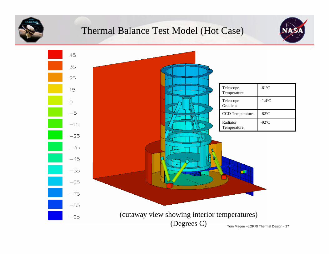
-92ºCRadiator Temperature
-82ºCCCD Temperature
-1.4ºCTelescope Gradient
-61ºCTelescope Temperature
Thermal Balance Test Model (Hot Case)
(cutaway view showing interior temperatures)(Degrees C)
Tom Magee –LORRI Thermal Design - 28
-110
-100
-90
-80
-70
-60
-50
-40
-30
-20
-10
0
10
20
30
40
50
8/27/04 0:00 8/28/04 0:00 8/29/04 0:00 8/30/04 0:00 8/31/04 0:00 9/1/04 0:00 9/2/04 0:00
Time of Day
Deg
rees
C
Radiator
Telescope
Baffle Tube
CCD
Baseplate
Cold Open
Hot Open
Hot, Gradient Heater On
Hot, Decontamination Heaters On
Hot, Closed, Decontamination Heaters On
Break Vacuum
LORRI Thermal Balance Test Data
Tom Magee –LORRI Thermal Design - 29
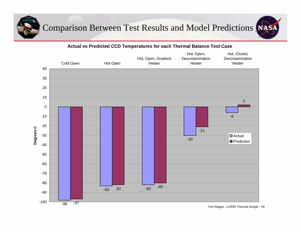
Comparison Between Test Results and Model Predictions
Actual vs Predicted CCD Temperatures for each Thermal Balance Test Case
-98
-83 -82
-30
-6
-97
-82 -80
-21
2
-100
-90
-80
-70
-60
-50
-40
-30
-20
-10
0
10
20
30
40Cold Open Hot Open
Hot, Open, GradientHeater
Hot, Open,Decontamination
Heater
Hot, Closed,Decontamination
Heater
Deg
rees
C
ActualPrediction
Tom Magee –LORRI Thermal Design - 30
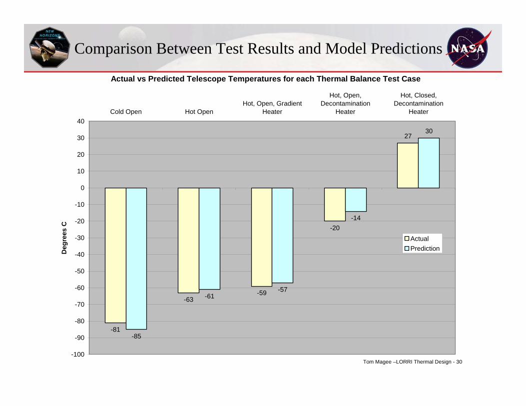
Comparison Between Test Results and Model Predictions
Actual vs Predicted Telescope Temperatures for each Thermal Balance Test Case
-81
-63-59
-20
27
-85
-61-57
-14
30
-100
-90
-80
-70
-60
-50
-40
-30
-20
-10
0
10
20
30
40Cold Open Hot Open
Hot, Open, GradientHeater
Hot, Open,Decontamination
Heater
Hot, Closed,Decontamination
Heater
Deg
rees
C
ActualPrediction
Tom Magee –LORRI Thermal Design - 31
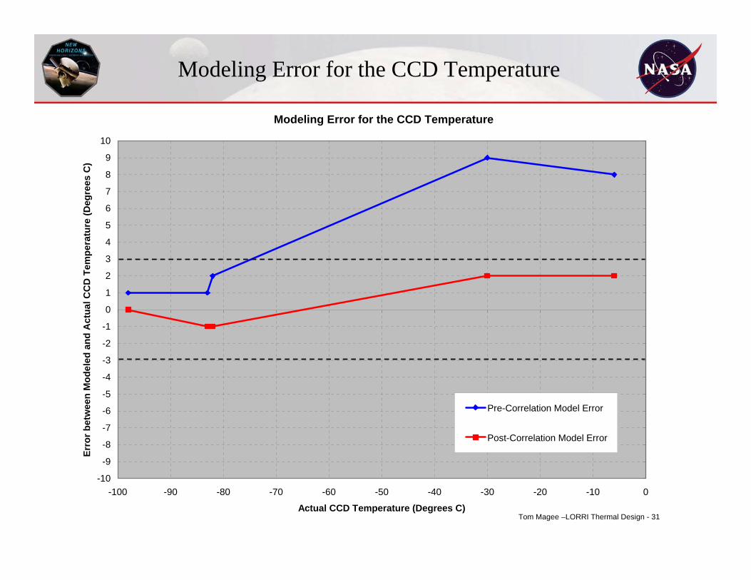
Modeling Error for the CCD Temperature
Modeling Error for the CCD Temperature
-10
-9
-8
-7
-6
-5
-4
-3
-2
-1
0
1
2
3
4
5
6
7
8
9
10
-100 -90 -80 -70 -60 -50 -40 -30 -20 -10 0
Actual CCD Temperature (Degrees C)
Erro
r bet
wee
n M
odel
ed a
nd A
ctua
l CC
D T
empe
ratu
re (D
egre
es C
)
Pre-Correlation Model Error
Post-Correlation Model Error
Tom Magee –LORRI Thermal Design - 32
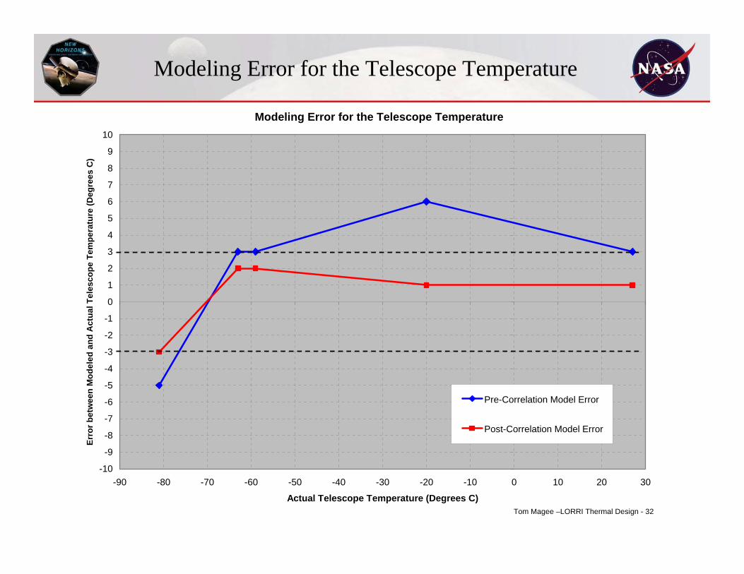
Modeling Error for the Telescope Temperature
Modeling Error for the Telescope Temperature
-10
-9
-8
-7
-6
-5
-4
-3
-2
-1
0
1
2
3
4
5
6
7
8
9
10
-90 -80 -70 -60 -50 -40 -30 -20 -10 0 10 20 30
Actual Telescope Temperature (Degrees C)
Erro
r bet
wee
n M
odel
ed a
nd A
ctua
l Tel
esco
pe T
empe
ratu
re (D
egre
es C
)
Pre-Correlation Model Error
Post-Correlation Model Error
Tom Magee –LORRI Thermal Design - 33
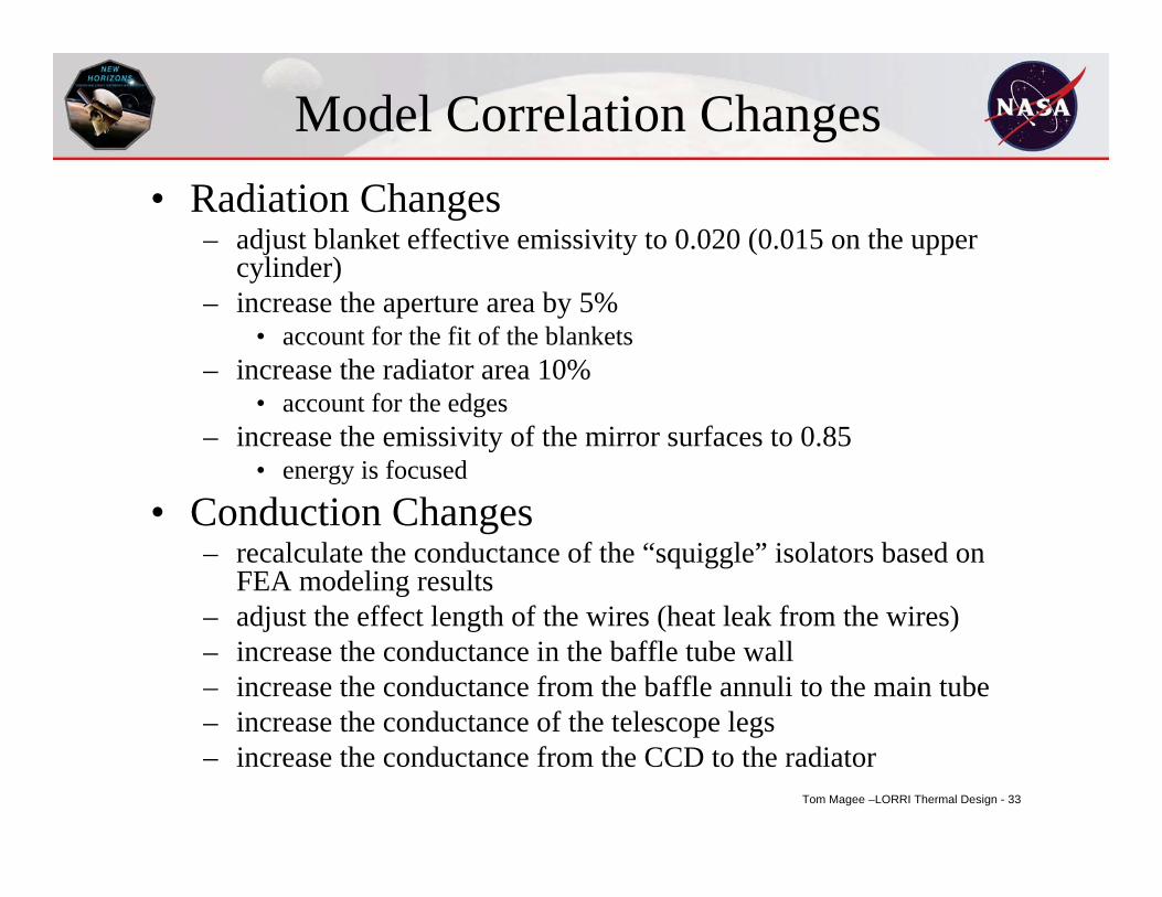
Model Correlation Changes• Radiation Changes
– adjust blanket effective emissivity to 0.020 (0.015 on the upper cylinder)
– increase the aperture area by 5%• account for the fit of the blankets
– increase the radiator area 10%• account for the edges
– increase the emissivity of the mirror surfaces to 0.85• energy is focused
• Conduction Changes– recalculate the conductance of the “squiggle” isolators based on
FEA modeling results – adjust the effect length of the wires (heat leak from the wires)– increase the conductance in the baffle tube wall– increase the conductance from the baffle annuli to the main tube– increase the conductance of the telescope legs– increase the conductance from the CCD to the radiator
Tom Magee –LORRI Thermal Design - 34
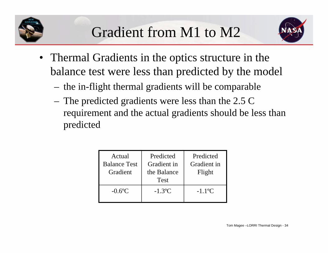
Gradient from M1 to M2• Thermal Gradients in the optics structure in the
balance test were less than predicted by the model– the in-flight thermal gradients will be comparable– The predicted gradients were less than the 2.5 C
requirement and the actual gradients should be less than predicted
-1.1ºC-1.3ºC-0.6ºC
Predicted Gradient in
Flight
Predicted Gradient in the Balance
Test
Actual Balance Test
Gradient
Tom Magee –LORRI Thermal Design - 35
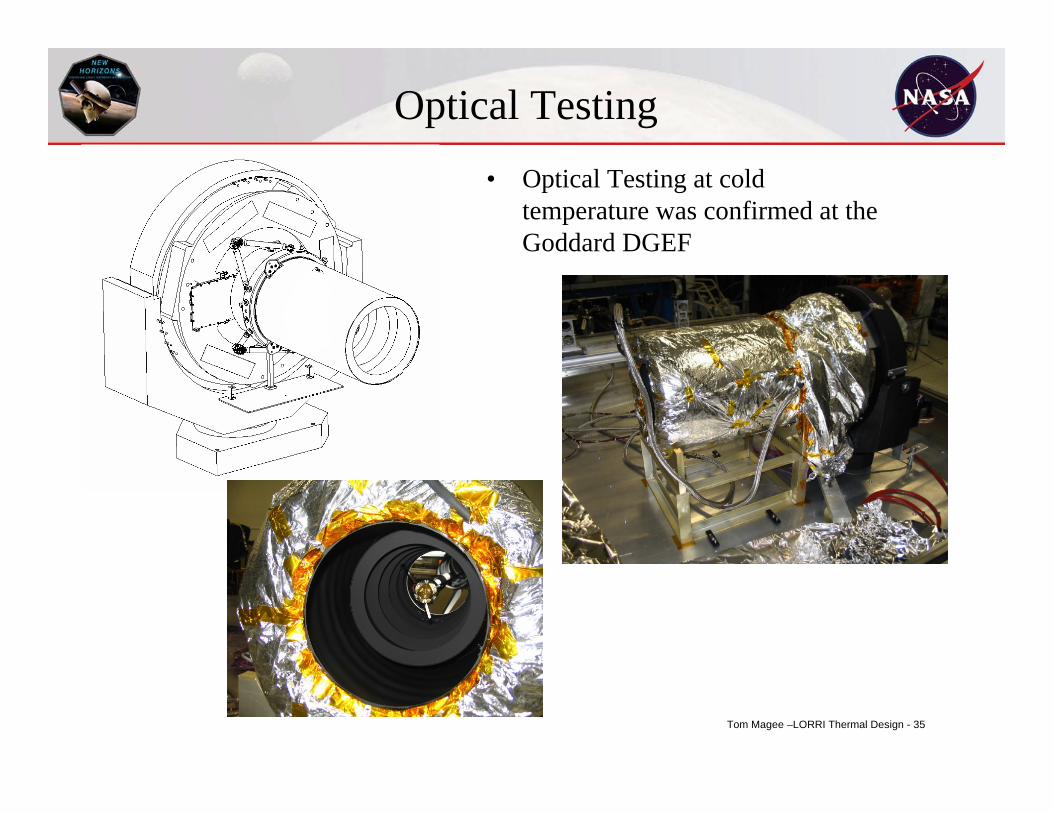
• Optical Testing at cold temperature was confirmed at the Goddard DGEF
Optical Testing
Tom Magee –LORRI Thermal Design - 36
Summary• A combination of modeling techniques was used to predict instrument
temperatures– finite difference (overall model)
• hand calculations (nodes and conductors)– finite element analysis (for complex structures)
• used to support the finite difference model– ray-trace software (for radiation modeling)
• A thermal balance test was performed to validate the thermal model– slight changes were required to correlate the model in all 5 test cases
• The flight version of the model was then updated with the same changes and revised flight predictions were made– the CCD should be colder than the requirement of -70ºC– The thermal gradient in the optics structure should be less than the
requirement of 2.5ºC• The LORRI telescope has been integrated with the New Horizons
Spacecraft and is awaiting launch in 2006 for a 2015 flyby.