
Wide-angle radiation pattern calculation of paraboloidal ...

N A S A
e c/I 4 z
T E C H N I C A L NOTE N A S A TN D-3543 e . I CI- c --
n m
THERMAL DISTORTIONS OF THIN-WALLED PARABOLOIDAL SHELLS
by Joseph E. WaZz
Langley Research Center Langley Station, Hampton, V,.
I
NATIONAL AERONAUTICS A N D SPACE A D M I N I S T R A T I O N WASHINGTON, D. C . AUGUST 1966 i I
https://ntrs.nasa.gov/search.jsp?R=19660024680 2019-08-27T20:55:07+00:00Z

TECH LIBRARY KAFB, NM
0330280
NASA TN D-3543
THERMAL DISTORTIONS OF THIN-WALLED PARABOLOIDAL SHELLS
By Joseph E. Walz
Langley Research Center Langley Station, Hampton, Va.
NATIONAL AERONAUTICS AND SPACE ADMINISTRATION
For sale by the Clearinghouse far Federal-Scientific and Technical Information Springfield, Virginia 22151 - Price $2.00

THERMAL DISTORTIONS OF THIN-WALLED PARABOLOIDAL SHELLS*
By Joseph E. Walz Langley Research Center
SUMMARY
Equations a r e presented to describe the linear behavior of a deep thin-walled shell of revolution subjected to an axisymmetric thermal loading. A solution is obtained for a paraboloid with a ring at the edge. Results are plotted showing the rotation of the tangent to the shell due to (1) constant temperature difference between shell and ring and (2) con- stant temperature gradient through the thickness of the shell.
INTRODUCTION
The radiation of the sun provides an attractive source of power for satellites and space vehicles. To transform the radiation of the sun into electrical power, a conversion system is required. In order to obtain usable amounts of electrical power, some con- version systems require concentration of the rays of the sun; thus, the concept of a solar concentrator has been developed. Several shapes of concentrators a r e conceivable, but most of the attention has been devoted to the paraboloidal shape because of its high con- centrating ability. question a r i s e s as to the effect that temperature gradients have on the shape of the shell forming this mirror and consequently on its concentrating ability.
In the utilization of a paraboloidal mir ror as a solar concentrator, the
In order to obtain maximum efficiency, efforts will be made to train the axis of the paraboloidal mir ror directly at the center of the sun; hence, axisymmetric temperature effects may be encountered. In preliminary studies (such as ref. 1) where the use of linear plate formulas have been employed, temperature gradients through the thickness of the paraboloid were shown to produce large overall distortions. Reference 2 develops a means of solving the general axisymmetric thermal problem for an isotropic shell of revolution which is based on deep shell theory; unfortunately, the numerical results in the illustrative example section appear to be in e r ror .
~
* The information presented herein is based in part upon a thesis submitted in partial fulfillment of the requirements for the degree of Master of Science in Engineering Mechanics, Virginia Polytechnic Institute, Blacksburg, Virginia, June 1965.
I

In the present paper equations governing the linear behavior of a general isotropic shell of revolution subjected to an axisymmetric temperature distribution are given. Deep shell theory, although different from that used in reference 2, is employed to obtain these equations. These equations are specialized fo r a paraboloid with a ring a t the edge subjected to a constant overall temperature change and a constant temperature gradient through the thickness; the ring may have a uniform temperature change which is different from that of the shell. The ability of the ring to res t r ic t the expansion and rotation of the edge of the shell can be varied by adjusting the stiffness parameters involved. Results are presented in equation form for stresses and displacements, and figures showing rotation of the tangent at any location a r e plotted for a wide range of parameters. An indication is given as to the effect that thermal distortions have on the concentrating ability of a paraboloid used as a solar concentrator.
SYMBOLS
The units used for the physical quantities defined in this paper a re given both in U.S. Customary Units and in the International System of Units (SI). (See ref. 3.)
Ar cross-sectional area of ring
a radius from axis to centroid of ring (see fig. 3)
b cross-sectional radius of circular ring (see fig. 3)
C extensional stiffness of shell, Eh
ErAr dimensionless ratio of extensional stiffness of ring to that of shell, - Ehr,
concentration ratio herein used as ratio of projected a rea of concentrator to
- C
CA area of aperture of an absorber located in focal plane
Eh3 D flexural stiffness of shell, 12(1 - v2)
E r Ir dimensionless ratio of flexural stiffness of ring to that of shell, - r 0 D
- D
E Young's modulus of shell
E r Young's modulus of ring
2

+ .
I
f
H
h
Ir
P
radial eccentricity of centroid of ring from point of attachment of ring to shell (see fig. 3)
axial eccentricity of centroid of ring from point of attachment of ring to shell (see fig. 3)
dX elliptic integral of first kind, lox 11 - k 2 sin2X
2 focal length of paraboloid, - r0
420
radial s t r e s s resultant
thickness of shell
moment of inertia of c ross section of ring about centroidal axis in plane of ring
integers
constant s
modulus of elliptic integral
distance in focal plane that a reflected ray misses focal point
radius of aperture of absorber
bending moments per unit length of sections of shell (see fig. 1)
applied uniform moment per unit length
normal s t r e s s resultants in meridional and circumferential directions, respectively (see fig. 1)
applied uniform force per unit length
3
I

radially distributed loading, positive in cr-direction ph
PV axially distributed loading, positive in +z-direction
Q transverse shear stress resultant
r radial distance to point on meridian of shell
r0 radial distance to edge of shell
T temperature change from stress-free datum
Tinner temperature change from datum of point on inner surface of shell
Touter temperature change from datum of point on outer surface of shell
T r uniform temperature change of ring from datum
Touter + Tinner T s = 2
U radial displacement of shell
- U nondimensional radial displacement of shell
U a total radial displacement uf attachment point of ring
uacl,uac2 radial displacements of point of attachment relative to centroid of ring
uc1,uc2 radial displacements of centroid of ring
V axial s t r e s s resultant
W axial displacement
- W nondimensional axial displacement
4
I

axial distance to point on meridian of shell
axial distance to edge of shell
Lam6 parameter defined by equation (13a); specialized for paraboloid by equation (38)
coefficient of linear thermal expansion of ring material
coefficient of linear thermal expansion of shell material
rotation of tangent of point on middle surface of shell from undeformed position to deformed position (see fig. 1)
r im angle
Kronecker delta (6ij = 0, if
s train in meridional and circumferential directions, respectively, at any
i # j; 6ij = 1, if i = j)
point in shell
strain in meridional and circumferential directions, respectively, at points on middle surface of shell
coordinate along inward normal of shell (see fig. 1)
expression defined by equation (41); specialized fo r paraboloid by equation (42)
circumferential coordinate
curvature changes in meridional and circumferential directions, respectively
5
($ parameter indicating amount of concavity of paraboloid,
Poisson's ra t io of shell material
r dimensionless coordinate specifying point on meridian, - r0
expression defined in equations (28); specialized for paraboloid by equation (39)
normal stress in meridional and circumferential directions, respectively
expression defined in equations (28); specialized for paraboloid by equation (40)
angle that tangent to a point on undeformed middle surface of shell makes with plane perpendicular to axis of shell (see fig. 1)
amplitude of elliptic integral
Subscript:
0 evaluated at < = 1
Pr imes denote derivatives with respect to 5 .
LINEAR AXISYMMETFUC SHELL EQUATIONS
The governing equations for a linear thermoelastic axisymmetric problem involving a shell of revolution are obtained by modifying the equations in reference 4 to include temperature effects. The positive directions of the stress resultants and couples, dis- placements, and rotation involved in the development of these equations a r e shown in figure 1.
St r e ss- Strain Relations
When transverse normal s t r e s s is neglected, the following s t r e s s strain relations hold as long as E, as, and v are taken to be constant over the range of temperatures being considered:
6

The assumption is made that the temperature is linear through the thickness of the shell; thus
( 3) T = T s + - A T P h
where
Ts = '(T inner + Touter) (4)
The following strain variations through the thickness are used (ref. 4) when attention is restricted to thin shells (that is, ratio of shell thickness to radius of curvature is small compared with one):
In obtaining the relationships expressed in equations (6), the deformations due to trans- verse shear and transverse normal s t r e s s are neglected; thus, points on the normal to the undeformed surface lie on the normal to the deformed surface. and couples are defined as
The stress resultants
7

Substitutions from equations ( l ) , (2), (3), and (6) into equations (7), after performing the required integrations, yield
where
C = E h 1 12(1 - v2)
Eh3 i D =
E qui1 ibr ium and Compatibility E quat ions
Equilibrium of forces in the axial and radial directions is found in reference 4 to be (H is the radial force resultant; V is the axial force resultant (see fig. 1)) i
and the moment equilibrium equation is
( r M 0 - COS cp + rE(H sin cp - V cos cp) = 0 (12)
where a prime denotes differentiation with respect to 5 , and
- a = E r') 2 + (z') j1'2
Z'
r' t a n c p = -
8

A compatibility relation is given which for small rotations /3 is
Strain Displacement Relations
Strain displacement equations given in reference 4 are
and for small rotations
where u and w are radial and axial displacements, respectively. Thus, substitution of s t ra ins from equations (8) into equations (15) and (16) yields
w = ~ ( N S - VNe) - r'pld'$ + z'aSTS dt;
The curvature changes are given as
and for small rotation
Development of Governing Second-Order Differential Equations
The complete system of field equations can be reduced to two ordinary second- order differential equations in two unknowns. To develop these equations, it is desirable, initially, to express all quantities in t e rms of H, V, p, and the distributed and thermal loads. are related to the axial and radial stress resultants by the following equations:
The normal s t r e s s resultant N5 and the transverse shear s t r e s s resultant Q
9

N5 = H cos cp + V sin SQ
Q = -H sin cp + V cos cp
Once pv is established, the solution for V from equation (10) is
Substitution of the moment expressions in equations (8) into the moment equilibrium equation (12) after f i r s t using the curvature changes given in equations (19) and (20) yields a second-order differential equation involving p and rH. The other differential equa- tion required is obtained by substitution of and T f rom equations (8), with Ne and N5 f rom equations (11) and (21), into the compatibility equation (14). By use of the following transformation ,
- 5
Y = -(rH) /z the two differential equations so derived become
where
I
J
(28) Equation continued on next page
10

[R]'+: 2 (21
+ = ($) + 2 (&) + - + @I (&)
and I Iref means the absolute value of a quantity evaluated at a suitably chosen refer-
ence point on the shell.
Approximate Solution to Governing Equations
It is convenient to consider separately the homogeneous and particular solutions of the equations. In equations (26) and (27) the quantity p2 is, in general, of the order of the ratio of a radius of curvature to the thickness of the shell and is large compared with unity. The functions 0 and + appearing in these equations are, in general, of the order of unity provided the shell is such that the thickness is slowly varying (it may not vary appreciably over a distance on the order of p h , where h is the average thickness
11

and R is a representative radius of curvature) and provided the functions a r e not eval- uated in a shallow region of the shell. Under these circumstances, for an approximate solution to the homogeneous parts of equations (26) and (27), it would be permissible to omit the 0 and the @ t e rms and put the equations in the following form:
where the subscript H re fers to the homogeneous part. Reference 4 seeks to obtain an asymptotic solution to equation (29) by considering the following ser ies :
As in reference 4 the solution of equation (29), except for small t e rms of order l/p, is obtained by retaining only the leading te rms in the ser ies in equations (30) and (31) to yield
where C1 and C2 are complex constants, - '' is taken to be 1, and 1 is
*(l + i)J+ d t . The case where - = -1 requires changing i to -i in the expo-
nents in equation (32).
I z' I Z'
I Z ' I
In the treatment of approximate particular solutions, it is to be observed that the right-hand sides of equations (26) and (27) consist of applied pressure loading te rms and thermal loading terms. With the stipulation that the derivative of the pressure loading with respect to 5 is not of order of magnitude greater than the loading itself, conven- tional membrane theory has been shown to provide an adequate approximate particular solution consistent with retaining only the leading t e rms in the homogeneous solution (ref. 5). under a similar condition, the f i r s t two t e rms on the left-hand sides of equations (27) and (26) would be neglected, and, as a result,
To obtain a particular solution (denoted by subscript P) for the thermal loading
12

which correspond to those obtained in reference 6 for constant thickness. As f a r as stresses a r e concerned, the retention of these particular solutions appears to be incon- sistent with retaining only the leading t e rms in the homogeneous solution and s t resses obtained in this manner are in question; however, meaningful values for the rotation of the tangent may be obtained away from the edge of the shell.
Separation of equation (32) into rea l and imaginary par ts and the addition of the particular solutions yields the complete solution for X and Y. Thus, the deformations may be evaluated once the geometry is specified.
PARABOLOIDAL SHELL WITH EDGE RING
The general equations developed in the preceding sections a r e now specialized to a paraboloid of revolution of constant thickness with a ring at the edge. there is no loading other than a thermal loading due to temperature changes, Ts of the shell and Tr of the ring, and constant temperature gradient through the thickness of the shell AT. The presence of a ring is considered because a paraboloid used as a solar concentrator may have a support ring attached at its edge, but other boundary con- ditions such as a f ree or clamped edge may be realized by suitably adjusting two stiffness parameters of the ring.
In particular,
The dimensionless coordinate .$ is used to specify a point on the meridian where
and r is the radial distance from the axis to the particular point on the meridian and ro is the radial distance to the edge. In this coordinate system a paraboloid is specified bY
where z is the axial location of a point, f is the focal length of the paraboloid, and 2
X = rg) . The r im angle y and X have the relationship expressed by the following
equation, and a plot of this relationship is shown in figure 2:
13

2x1I2 tan y = - 1 - h (37)
The r im angle y is the angle formed between the axis of the paraboloid and a line passing through a point on the r im and the focus (fig. 2).
The Lam6 parameter, given by equation (13a), for a paraboloid in this coordinate system be comes
and the f i r s t two quantities of equations (28) become
P =
when the apex is selected as the reference point.
I l = p I , 5
in this coordinate system, becomes
Another quantity q defined as
d5
is an elliptic integral of the f i rs t kind and X dX where F(k,x) =
(39)
(4 3)
The particular solutions Xp and YP, as given by equations (33) and (34) a r e both zero, since no applied loading is considered besides thermal loading, the shell is of con- stant thickness, and the temperature components a r e constant. Thus, the homogeneous
14
...

I
solutions of equations (26) and (27) a r e the complete solutions. For the case of a parab- oloid which is closed at the apex, C2 is equal to zero (ref. 7) and the following solution is obtained:
X =
Y =
where K1 and K2 a r e
(44)
(4 5)
dimensionless constants obtained by nondimensionalizing the real and imaginary par ts of Henceforth, as in equations (44) and (45), the sub- script o indicates a quantity evaluated at the point 5 = 1. Equations (44) and (45), with the use of equations (24) and (25), permit the evaluation of s t resses and deformations once the constants K1 and K2 have been evaluated from the boundary conditions.
C1.
Deflection and Rotation of Edge of Shell
Boundary conditions for a shell having a ring attached at i ts edge a r e such that deformation and force compatibility must be maintained at the attachment point of the ring and the shell. Thus the radial displacement u of the shell at the edge must be equal to the radial displacement of the ring at the point of attachment. Also, if the method of attachment permits transfer of moment, the edge of the shell and the ring must rotate the same amount about an axis perpendicular to the c ross section of the ring.
For the shell, f rom equations (24) and (44), the rotation at any point is
and thus at the edge of the shell
po = 2/3(1 - ~ 2 ) ( 1 + A)’l8(K1 cos qo - K2 sin qo) (4 7)
where the subscript o denotes evaluation at 5 = 1. An approximate relation for the u-displacement, based on the consideration that the solution of the governing equations neglects te rms of order l /p compared with 1, is found from equations (17), (ll), (25), and (45) to be
1/2e-(q0-q)[Kl(sin q + cos q) + K~(COS q - sin q) + ro,g%Ts (48) 1 15
I

A nondimensionalized radial displacement U is obtained by dividing equation (48) by h; thus, at the edge of the shell
Eo = (1 + X)-ll8p sin qo + cos qo) + K2 (cos qo - sin qoi] + rO %Ts (4 9)
Deflection and Rotation of Ring
For a ring subjected to a uniform radial loading per unit length P acting in the plane of the ring, there is no rotation; and the displacement loading is given by
ucl in the direction of
(See ref. 8.) tending to twist the ring inside out, there is no displacement but a rotation in the direc- tion of the moment such that
For a ring subjected to a uniform moment per circumferential length m
(See ref. 8.) If the ring has attained a uniform temperature increase Tr from initial equilibrium temperature, the centroid of the c ross section of the ring has an additional displacement
Since, in general, the ring is attached at some point other than i ts centroid, addi- tional effects must be considered. Because the radial force does not act necessarily through the centroid, the moment created by this eccentricity must be included in equa- tion (51). Rotation of the ring produces a relative displacement between the centroid and the point of attachment. For small positive angular rotation Pr, the radial displacement of the point of attachment relative to the centroid is
where e, is positive when the point of attachment is figure 3. The displacement of the point of attachment is
above the centroid as shown in relative to the centroid due to
(53)
Tr
16

where eh is positive when the centroid of the ring is at a distance greater than ro from the axis of the paraboloid. Thus, the total radial displacement U a of the point of attachment is given by
ua = u c ~ + uc2 + Uacl + Uac2
Evaluation of Constants
(55)
In the process of evaluating the constants K1 and K2 L e r e are three independ- ent temperature t e rms to consider. It is possible, because of the linearity of the prob- lem, to consider each effect separately and then combine these effects to obtain the total effect. Thus,
K2 = K21(asTs) + K22(@~ AT) + K23(arTr) (57)
To insure compatibility of the shell-ring structure, the nondimensional radial dis- placement of the edge of the shell determined from equation (49) is set equal to the non- dimensional radial displacement of the point of attachment of the ring determined from the proper nondimensionalization of equation (55). Similarly, the rotation at the edge of the shell determined from equation (47) is set equal to the rotation of the ring determined from equation (51). From force compatibility considerations, the quantities P and m appearing in equations (50) and (51) a r e
Pa = -Horo (58)
m a = - ( M to +Hoev)ro (59)
(See fig. 3.) After the appropriate quantities from equations (8), (19), (25), (45), (46), (50), (52), (53), (54), (58), and (59) have been substituted into equations (55) and (51), the two aforementioned equalities result in two simultaneous equations which have the form
17

(6 1) -
g21Klj + g22K2j = g2 j
where the subscript j takes on the value 1, 2, or 3, depending on the temperature com- ponent of interest and
cos qo - pF(1 + A)- ' l4(sin qo + cos q ro + eh gll = -( ro ) sin qo + c --
g12 = -( ro roeh) + cos qo - c - - sin qo - p ~ ( l + A ) - ~ / ~ ( ~ ~ ~ qo - sin q,
18

Within the limits of the accuracy of the development and solution of equations (26) and (27), the deflections, s t r e s s resultants, and couples become approximately
62j 12(1 - v)
as AT - K2j(sin q + COS q) 3 - 12(1 - v) 62j
19

where Sij, called Kronecker delta, is defined as
and constants %j representing nondimensional rigid body translations are to be deter-
mined from the boundary condition on w. The total value of a quantity is therefore the sum of the components (for example, p = p1 + p2 + p3).
RESULTS AND DISCUSSION
Stresses and deformations throughout a paraboloid shell with a ring attached at the edge can be calculated from equations (64) to (71). Because the rotation of the tangent p has the most significant effect on solar concentrator performance, results are presented for the variation of p with radial distance for two types of temperature distributions and various values for the structural and geometric parameters. The temperature dis- tributions represented a r e (1) uniform temperature change of the shell and a possibly different temperature change of the ring from the datum temperature (consideration of + -Tr - asTs), and (2) uniform temperature gradient through the thickness of the shell with its middle surface and the ring at the datum temperature (consideration of as AT). Finally, results are presented of simplified efficiency calculations described in the appendix to give some idea of the influence of these thermal loadings on the performance of a solar concentrator.
Effect of Temperature Difference Between Shell and Ring
The rotation of the tangent to the shell p as a function of radial distance r/ro is shown in figures 4 to 9 for temperature distribution a r T r - asTs. All results a r e fo r h = 1/3 (except fig. 7), ro/h = 5000 (except fig. 8), and no ring eccentricities (except fig. 9). In figures 4 to 9 for the case of the same material in the ring and the shell and the same uniform temperature change in the ring and the shell, no rotations occur any- where. It must be borne in mind that the slope changes presented in this set of figures a r e those of a materia1 point of the shell and are not necessarily those of a spatial coor- dinate. In temperature distribution a r T r - asTs the Ts component causes the shell to experience an expansion, and at a spatial coordinate there is a slope change because one material point is replaced by another material point which has a different slope than the original point. In this instance most of the paraboloid has expanded to the shape of a new paraboloid which has its focal length 1 + s T s times as large as the original focal length.
20
Results for various values of the relative extensional and flexural stiffness param- -- e ters For small values of E and 5 the ring stiffnesses a r e small relative to those of the shell, and the shell is relatively unaffected by the presence of the ring. As the values of C and 5 a r e increased, the region near the edge of the shell is beginning to be affected by the presence of the ring. When the values of and approach infinite values, the edge of the shell becomes "clamped." In this condition rotation of the tangent to the shell at the edge is not allowed, and the radial displacement is constrained to be the same as that of the ring caused by the temperature change of the ring.
and 5 for a constant ratio of '3 to E (D/C = 10 000) a r e shown in figure 4.
-
- Results for a large value of the relative flexural stiffness parameter, D = 10 000,
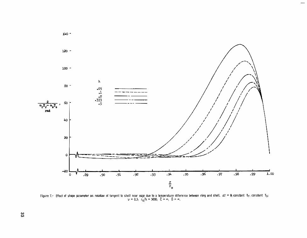
coupled with various values of E, and results for a moderately large value of the rela- tive extensional parameter, figures 5 and 6, respectively. Effects of variations in the shape parameter X and var- iations in the radius-thickness ratio ro/h a r e shown in figures 7 and 8, respectively, for infinitely large values of both and D. A s the shell becomes flatter (X decreasing or r im angle decreasing), the rotations become larger in magnitude every- where in the edge region and the edge effects a r e propagated farther into the shell (fig. 7). Thus from the point of view of keeping shell rotations small, larger r im angles a r e desirable. Finally, the influence of small axial eccentricities of the ring are illus- trated in figure 9. Effects of small radial eccentricities of the ring a r e not shown because they a r e negligible.
- C = 0.1, coupled with various values of are shown in
Effect of Temperature Gradient Through Thickness of Shell
The rotation of the tangent to the shell p as a function of radial distance r/ro is shown in figures 10 to 12 for temperature distribution or, AT. The effects of various values of the relative stiffness parameters C and D for a constant ratio of D/C = 10 000 a r e shown in figure 10 for a shell for which X = 1/3 and ro/h = 5000. A s the values of both C and D approach infinitely large values, p approaches zero throughout the shell. The f r ee edge case where C = = 0, on the other hand, leads to the largest rotations. Effects of variation in the shape parameter X are shown in fig- ure 11 for ro/h = 5000 for the free edge case. A s in the case of temperature distribu- tion C+Tr - as AT, larger values of X lead t o reduced magnitudes of rotation. The results of linear flat-plate theory used for preliminary studies such as reference 1 fo r which
- - -
-
21
a r e not given in this figure since values obtained from this formula a r e found to be much larger and affect the entire shell. Finally, effects of variations in ro/h a r e shown in figure 12 for h = 1/3 for the f ree edge case.
Influence of Thermal Effects on Concentrator Performance
The loss in efficiency due to thermal distortions based on the assumptions and analysis contained in the appendix is shown in figures 13 and 14. these results are based on the assumption that solar energy is coming from a point source. Furthermore, interaction of thermal distortions with other features which reduce efficiency has not been incorporated. The effect on efficiency of temperature distribution a r T r - asTs is shown in figure 13 when AT is zero, and the effect of temperature distribution % AT when QrTr - aSTS is zero is shown in figure 14.
It is emphasized that
The effect of temperature distribution a r T r - asTs on efficiency is shown in fig- ure 13 for a shell having values of h = 1/3, ro/h = 5000, and v = 0.3. The shell has an attached ring with properties such that = 1 and 5 = 106 which simulates one of the most detrimental conditions. The efficiency is shown as a function of the a rea concen- tration ratio, herein used as the ratio of the projected a rea of the paraboloid to the a rea of the aperture of an absorber in the focal plane, for values of equal to
100, 50, 20, and 10 pin./in. (pm/m). When = as = 10 pin./in-OF ( 18 - L:K), which
is roughly the value of this coefficient for metals, these curves correspond to loo F (5.6O K), 5' F (2.8O K), 2O F (1.l0 K), and lo F (0.56O K).
J a r T r - orsTsl
The effect of temperature distribution as AT on efficiency is shown in figure 14 for a shell having values of ro/h = 5000, v = 0.3, and h = 1/3. The shell does not have an attached ring and this case leads to the greatest losses in efficiency due to a tempera- ture gradient through the thickness of the shell. Curves are presented for four values of as AT. Since the a rea in which thermal distortions occur is small, it is not surprising that the loss in efficiency is not great.
CONCLUDING REMARKS
Linear equations a r e presented to describe the action of a paraboloid under axisym- metric temperature loading consisting of a constant temperature change of the shell, con- stant temperature gradient through the thickness of the shell, and a constant temperature change of an attached ring. Slope distortions a r e found to be confined to a region near the edge of the shell and it is found that larger r im angles a r e desirable since they restrict the distortions to smaller magnitudes and to a smaller region.
22

For the case of a paraboloidal shell with a free edge subjected to a constant tem- perature gradient through i t s thickness, the resul ts for preliminary purposes based on flat-plate formulas indicate the entire surface is affected and the rotations involved are much greater than those determined by the present analysis. ring relieves the distortions due to a temperature gradient through the thickness of the shell. The attached ring however becomes the source of loading on the shell when the shell is at one temperature and the ring at another temperature. The larger the ratio of the extensional stiffness of the ring compared with that of the shell, the greater the distortions.
It is found that an attached
Langley Research Center, National Aeronautics and Space Administration,
Langley Station, Hampton, Va., April 19, 1966.
23
I

APPENDIX
EFFICIENCY CONSIDERATIONS
The objective of this appendix is to estimate the loss in concentrating efficiency due to thermal distortions. The concentrating efficiency used herein is defined to be the ratio of the specularly reflected energy directed within a prescribed a rea in the focal plane divided by the total specularly reflected energy (shadowing effects of the absorber being neglected). A point source of energy is treated. From this simplified analysis an idea might be gained as to the influence of temperature differences on the performance of a solar concentrator. The interactions of thermal distortions with other features which also reduce the efficiency of the collecting system such as, the sun's finite image, irregularities in the concentrator surface, and so forth, have not been included.
Consider the reflecting surface being distorted at a point such that a ray which originally was directed to the focus is now displaced a distance 2 The point under consideration is shown in figure 15 after the reflecting surface has undergone a positive rotation. Attention here is restricted to a point within the region near the edge of the shell for which consideration of the effect of the rotation alone is sufficient since it can be shown that the effects of vertical and radial displacements a r e of higher order.
in the focal plane.
When transverse shearing deformations a r e neglected as was done in the shell development, the rotation of the tangent to the reflecting surface is the same as the rota- tion of the tangent to the middle surface p which can be determined from equation (71). From the geometry of figure 15,
2 = r - (f - z)tan(2cp - 2p) (AI)
Nondimensionalization of equation (Al) by dividing by ro yields
where geometrical considerations have been employed and in the expansion of tan(2cp - 2p) in powers of p, p2 and higher te rms have been neglected. Equation (A2) may be rewritten as
24

APPENDIX
where sin 4cp has been expressed as a function of C;, after cp has been determined through the use of equations (35), (36), and equation (13b) to be
If an absorber has a flat circular aperture of radius la in the focal plane,
where CA is the area concentration ratio herein defined as the ratio of the projected area of the paraboloid to the area of the aperture of the absorber. At a particular point, r/ro, if the absolute value of 1 /ro determined from equation (A3) is greater than 1 / G , the reflected energy from that point is considered lost and if the absolute value of 1 /ro is less than l/p~, the reflected energy from that point is considered to be collected. concentrator from which energy is collected can be found graphically and the ratio of this area to the total concentrator projected area is the efficiency. The results shown in figures 13 and 14 are obtained by selecting several values of the concentration ratio and calculating the corresponding efficiency.
For a particular value of the concentration ratio, the projected area of the
25

REFERENCES
1. Dresser, D. L.: Elements of Solar Collector Design. Paper No. 61-24, Inst. Aero- space Sci., Jan. 1961.
2.. Stern, G. S.: Thermoelastic Analysis of a Parabolic Shell. J e t Propulsion Lab., Calif. Inst. Technol., Aug. 1, 1963.
Tech. Rept. No. 32-479,
3. Mechtly, E. A.: The International System of Units - Physical Constants and Conver- sion Factors. NASA SP-7012, 1964.
4. Reissner, Eric: On the Theory of Thin Elastic Shells. Reissner Anniversary Volume: Contributions to Applied Mechanics, J. W. Edwards, 1949, pp. 231-247.
5. Hildebrand, F. B.: On Asymptotic Integration in Shell Theory. Elasticity, McGraw- Hill Book Co., Inc., 1950, pp. 53-66.
6. Lur'e, A. I.: Statics of Thin-Walled Elastic Shells. AEC-tr-3798, U.S. At. Energy Comm., Oct. 1959.
7. Novozhilov, V. V. (P. G. Lowe, trans.): The Theory of Thin Shells. P. Noordhoff, Ltd. (Groningen, The Netherlands), c.1959.
8. Fligge, Wilhelm: Stresses in Shells. Second printing, Springer-Verlag (Berlin), 1962.
26

z (1
V
I z + w A
1 I I r
(a) Side view of shell element in undeformed and deformed positions.
Figure 1.- Stress resultants, couples, and displacements.
(b) Shell element.
I

rad
1.6
1.4
1.2
1.0
. .6
.4
.2
0
Figure 2.- Relationship of rim angle to parameter indicating amount of concavity of paraboloid. h = (ro/iY)*

- +’ -+u - + P -4+p . I I u
(a) Geometry of shell-ring structure. (b) Internal reactions at attachment point of ring to shell.
Figure 3.- Geometry and internal reactions on an axial section of shell-ring structure.

W 0
B cc T - asTs
rad r r
J
0 " .g1 .92 93 0 9 4 .95 .96 .97 -98 .99 1.00
T - =0
Figure 4.- Effect of relative extensional and bending stiffness of a r i n g o n rotation of tangent to shel l near edge due to a temperature difference between r i n g and shell. AT = 0; constant Tr; constant Ts; v = 0.3; A = 1/3; r o / h = 5000; e, = 0; eh = 0.

100 -
A I I I I I I I I I I
rad
Figure 5.- Effect of relative extensional stiffness of a r i n g of constant bending stiffness on rotation of tangent to_shell near edge due to a temperature difference betweer. r i n g and shell. AT = 0; constant Tr; constant TS; u = 0.3; h = 1/3; ro/h = 5000; D = 1OooO; ev = 0; eh = 0.

w hl
120
80
60
rad 40
20
1 13 100
1000 10000
00
A I 1 I I I I I I I 1 0 -91 .92 -93 -94 .95 .96 .9; .98 -99 1.00
Figure 6.- Effect of relative bending stiffness of a ring of constant extensional stiffness on rotation of tangent to shell near edge due to a temperature difference between ring and shell. AT = 0; constant Tr; constant Ts; u = 0.3; A = V3; ro/h = 5000; C = 0.1; 4( = 0; eh = 0.
r rO
Figure 7.- Effect of shape parameter on rotation of tangent to shel l near edge due to a teFperatuE difference between r i n g and shell. AT = 0; constant Tr; constant Ts; u = 0.3; ro/h = 5000; C = a; D = a.
W W

w rp
160
I20
-, 8 0 - a T - asTs
rad r r
40
0
.. -
-
-
&O L
h
-40 I, A I I I I I I I 1 I 1 I I o v .89 .90 * 91 .92 .93 .94 .95 .96 .97 .98 .99 1.00
Figure 8.- Effect of ro/h on rotation of tangent to shell near edge due to a tempeIature dif_ference between ring and shell. AT = 0; constant Tr; constant Ts; v = 0.3; h = 1/3; C = m; D = m.

.030 -----
6 0 -
40 -
-, 20- OL T - UsTs
rad r r
0
-20 -
-40 I I I I I I I I I 92 .93 .94 95 * 96 97 -98 .99 1.00
Figure 9.- Effect of axial eccentricity of ring on rotation of tangent to shell near edge due a tempe_rature difference between ring and shell. AT = 0; constant Tr; constant Ts; v = 0.3; h = 1/3; ro/h = 5000; C = 0.1; D = 10 000; eh = 0.
w Ln

w Q,
LOO
80
60
4c aSm ’ rad
2c
92 -93
Figure 10.- Effect of relative extensional and bending stiffnesses of a r i n g on rotation of tangent to shell near edge due to a temperature gradient through thickness of shell. Constant AT; arTr - aSTS = 0; u = 0.3; h = 113; ro/h = 5000; ev = 0; eh = 0.

W 4
4 0 A I I I I I 1 I I I I I I
0 ” 089 -90 91 .92 .93 .!% 95 .!% -97 -98 .99 1.00
0 A-
Figure 11.- Effect of shape parameter on rotation of tangent to shell near edge due to a tcmperatuie gradient through thickness of shell. Constant AT: arTr - asTS = U; v = 0.3; ro/h = 5000; C = 0; D = 0.

240
200
160
120
B aaaT ’
80 rad
- rO h
1000 2000 3000 -- 5000 10000 ----- 20000
- - - - - - - --
I i I i
h i I I I I I I I I I I 1
.a9 .90 .91 .92 93 0 9 4 95 .96 -97 0 % .gg 1.00 0 ” 4 0 1 I
r - =0
Figure 12.- Effect of ro/h on rotation of tangent to shell near edge due to a temperature gradient through thickness of shell. Constant AT; arTr - asTs = 0; u = 0.3; A = 11’3; c = 0; 0 = 0.

3 *97 - u rl 1 .96 -
d -
3 -95 - I! 8 .94 - rl
c,
-93
.92
e 9 1
-
-
Concentration ratio, CA
Figure 13.- Effect of thermal distortions near edge of a paraboloid due to a temperature difference between ring and shell on concentrating efficiency a_s a function of concentration ratio. Source of energy is treated as a point source. AT = 0; constant Tr: constant Ts; v = 0.3: A = 1/3; ro/h = Moo; C = 1; D = 106; e, = 0; eh = 0.

rp 0
I I I I I I I I I I I I I I I I I I I 1 I I I 1 I l l
loo0 10,ooo 100,Ooo 100
Concentration ratio, c A
Figure 14.- Effect of thermal distortions near edge of a paraboloid due to a temperature gradient through thickness of shell on the concentrating elficiency-as a function of concentration ratio. Source of energy is treated as a point source. Constant AT; arTr - asTs = 0; u = 0.3; A = 113; ro/h = 5000; C = 0; D = 0.

I r - I
Figure 15.- Effect of rotation of tangent to shell on path of a reflected ray.
NASA-Langley, 1966 L-3801 4 1

“The aeronautical and space activities of the United States shall be conducted so as to contribute . . . to the expansion of hiiman knowl- edge of phenomena in the atmosphere and space. The Administration shall provide for the widest practicable and appropriate dissemination of information concerning its activities and the results thereof .”
-NATIONAL AERONAUTICS AND SPACE ACT OF 1958
NASA SCIENTIFIC AND TECHNICAL PUBLICATIONS
TECHNICAL REPORTS: important, complete, and a lasting contribution to existing knowledge.
TECHNICAL NOTES: of importance as a contribution to existing knowledge.
TECHNICAL MEMORANDUMS Information receiving limited distri- bution because of preliminary data, security classification, or other reasons.
CONTRACTOR REPORTS: Technical information generated in con- nection with a NASA contract or grant and released under NASA auspices.
TECHNICAL TRANSLATIONS: Information published in a foreign language considered to merit NASA distribution in English.
TECHNICAL REPRINTS: Information derived from NASA activities and initially published in the form of journal articles.
SPECIAL PUBLICATIONS: Information derived from or of value to NASA activities but not necessarily reporting the results .of individual NASA-programmed scientific efforts. Publications include conference proceedings, monographs, data compilations, handbooks, sourcebooks, and special bibliographies.
Scientific and technical information considered
Information less broad in scope but nevertheless
Details on the availability or these publicafions may be obtained from:
SCIENTIFIC AND TECHNICAL INFORMATION DIVISION
NATIONAL AERONAUTICS AND SPACE ADMINISTRATION
Washington, D.C. PO546


![THE PARABOLOIDAL REFLECTOR ANTENNA IN RADIO …lib.iszf.irk.ru/The Paraboloidal Reflector Antenna... · chapter reference lists as [Gold, pp]. We omit a treatment of polarisation.](https://static.fdocuments.in/doc/165x107/5f71221125ae015eed4f9967/the-paraboloidal-reflector-antenna-in-radio-libiszfirkruthe-paraboloidal-reflector.jpg)

