Thermal Design of Lithium Sulfur Batteries · 1 REVB Next Generation Battery Technology Thermal...
27
REVB Next Generation Battery Technology Thermal Design of Lithium Sulfur Batteries R. Purkayastha, G. Minton, S. Walus, M. Wild OXIS Energy COMSOL Conference, Munich 2016 13/10/2016
Transcript of Thermal Design of Lithium Sulfur Batteries · 1 REVB Next Generation Battery Technology Thermal...
1
REVBNext Generation Battery Technology
Thermal Design of Lithium Sulfur BatteriesR. Purkayastha, G. Minton, S. Walus, M. Wild
OXIS Energy
COMSOL Conference, Munich 2016
13/10/2016
2
REVB
Revolutionary Electric Vehicle Battery – Focus on Automotive Applications
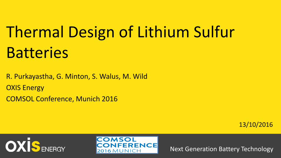
Model led R&D approach at OXIS Goal : To develop a battery module demonstrator
Company Confidential
3
REVB
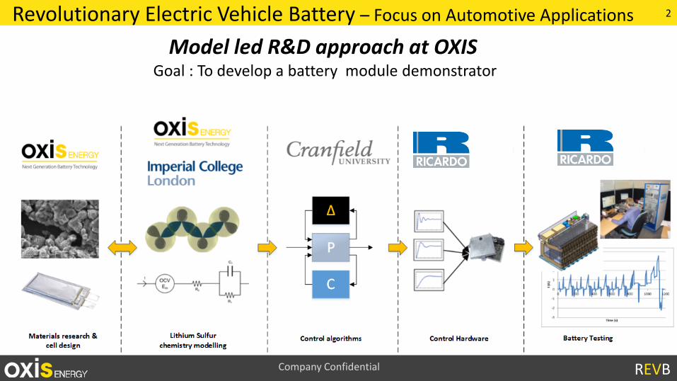
REVB Focusses on two main fronts
Cell Development Modelling
REVB takes the best ofcurrent materials researchat OXIS and puts that intoa cell
Modelling allows us to gain a more fundamental understanding of mechanisms : predict and optimise with minimal experiments
Validation
Observation
An example of this is thermal management of automotive cells : How dowe investigate and mitigate increased heat generation ?
4
REVB
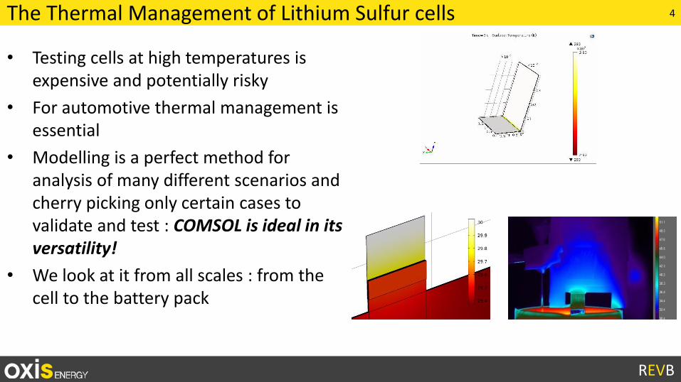
The Thermal Management of Lithium Sulfur cells
• Testing cells at high temperatures is expensive and potentially risky
• For automotive thermal management is essential
• Modelling is a perfect method for analysis of many different scenarios and cherry picking only certain cases to validate and test : COMSOL is ideal in its versatility!
• We look at it from all scales : from the cell to the battery pack
5
REVB
Outline : From micro to macro• Cell Design : Weld resistance
• Battery Pack : Polysulfide shuttle and thermal runaway
• Pack Integration : Laminar Flow
6
REVB
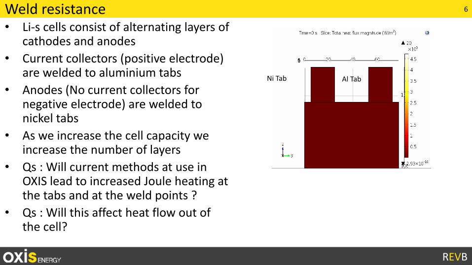
Weld resistance• Li-s cells consist of alternating layers of
cathodes and anodes
• Current collectors (positive electrode) are welded to aluminium tabs
• Anodes (No current collectors for negative electrode) are welded to nickel tabs
• As we increase the cell capacity we increase the number of layers
• Qs : Will current methods at use in OXIS lead to increased Joule heating at the tabs and at the weld points ?
• Qs : Will this affect heat flow out of the cell?
Al TabNi Tab
7
REVB
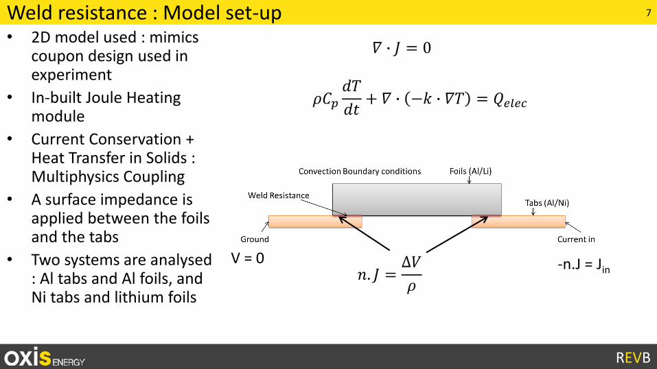
Weld resistance : Model set-up• 2D model used : mimics
coupon design used in experiment
• In-built Joule Heating module
• Current Conservation + Heat Transfer in Solids : Multiphysics Coupling
• A surface impedance is applied between the foils and the tabs
• Two systems are analysed : Al tabs and Al foils, and Ni tabs and lithium foils
V = 0 -n.J = Jin𝑛. 𝐽 =∆𝑉
𝜌
𝛻 ∙ 𝐽 = 0
𝜌𝐶𝑝𝑑𝑇
𝑑𝑡+ 𝛻 ∙ −𝑘 ∙ 𝛻𝑇 = 𝑄𝑒𝑙𝑒𝑐
8
REVB
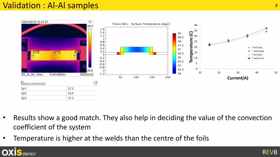
Validation : Al-Al samples
• Results show a good match. They also help in deciding the value of the convection coefficient of the system
• Temperature is higher at the welds than the centre of the foils
9
REVB
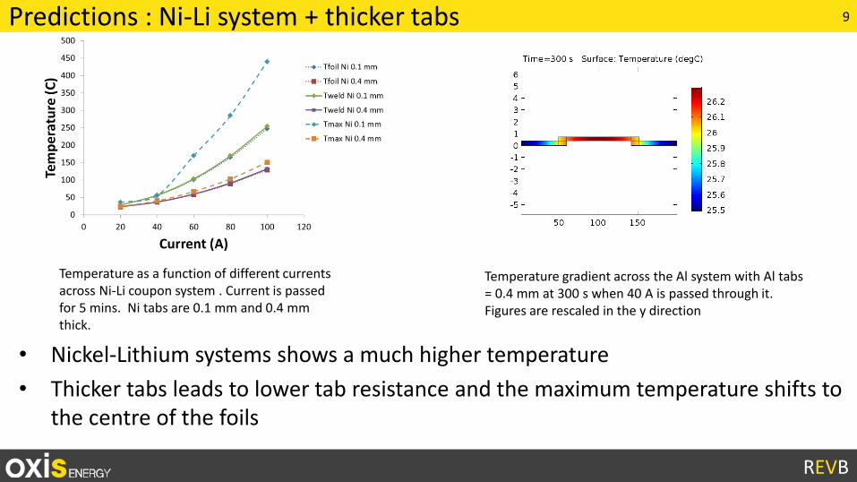
Predictions : Ni-Li system + thicker tabs
• Nickel-Lithium systems shows a much higher temperature
• Thicker tabs leads to lower tab resistance and the maximum temperature shifts to the centre of the foils
Temperature gradient across the Al system with Al tabs = 0.4 mm at 300 s when 40 A is passed through it. Figures are rescaled in the y direction
Temperature as a function of different currents across Ni-Li coupon system . Current is passed for 5 mins. Ni tabs are 0.1 mm and 0.4 mm thick.
10
REVB
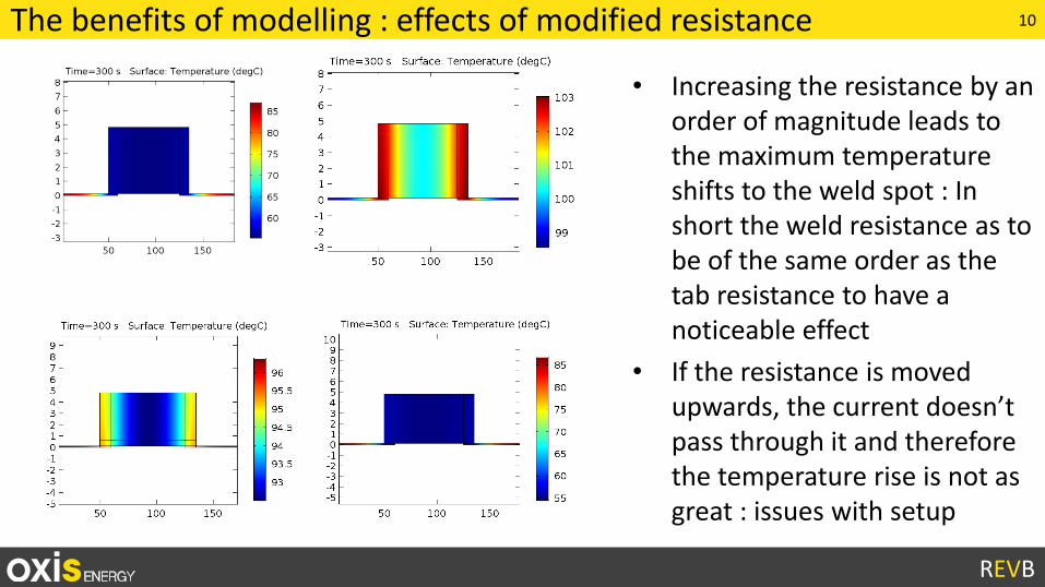
The benefits of modelling : effects of modified resistance
• Increasing the resistance by an order of magnitude leads to the maximum temperature shifts to the weld spot : In short the weld resistance as to be of the same order as the tab resistance to have a noticeable effect
• If the resistance is moved upwards, the current doesn’t pass through it and therefore the temperature rise is not as great : issues with setup
11
REVB
Outline : From micro to macro• Cell Design : Weld resistance
• Battery Pack : Polysulfide shuttle and thermal runaway
• Pack Integration : Laminar Flow
12
REVB
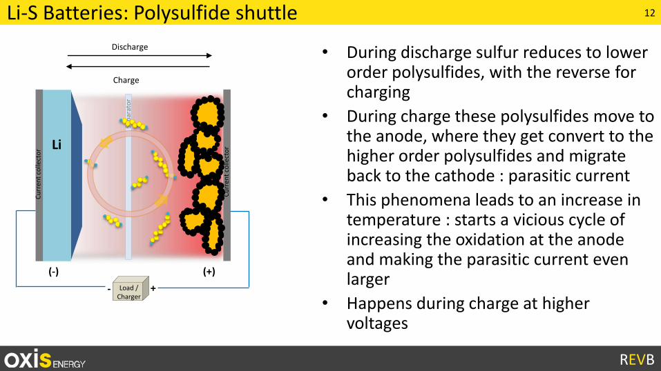
Li-S Batteries: Polysulfide shuttle
Li
Cu
rren
tco
llect
or
Cu
rren
tco
llect
or
(-) (+)
Sep
arat
or
+- Load / Charger
Discharge • During discharge sulfur reduces to lower order polysulfides, with the reverse for charging
• During charge these polysulfides move to the anode, where they get convert to the higher order polysulfides and migrate back to the cathode : parasitic current
• This phenomena leads to an increase in temperature : starts a vicious cycle of increasing the oxidation at the anode and making the parasitic current even larger
• Happens during charge at higher voltages
Charge
13
REVB
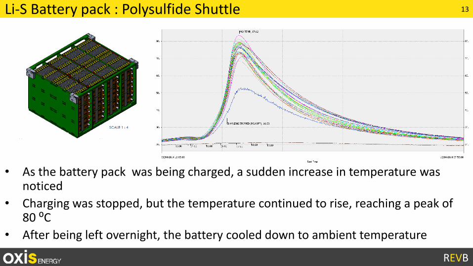
Li-S Battery pack : Polysulfide Shuttle
• As the battery pack was being charged, a sudden increase in temperature was noticed
• Charging was stopped, but the temperature continued to rise, reaching a peak of 80 ⁰C
• After being left overnight, the battery cooled down to ambient temperature
14
REVB
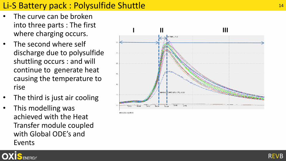
Li-S Battery pack : Polysulfide Shuttle• The curve can be broken
into three parts : The first where charging occurs.
• The second where self discharge due to polysulfide shuttling occurs : and will continue to generate heat causing the temperature to rise
• The third is just air cooling
• This modelling was achieved with the Heat Transfer module coupled with Global ODE’s and Events
I IIIII
15
REVB
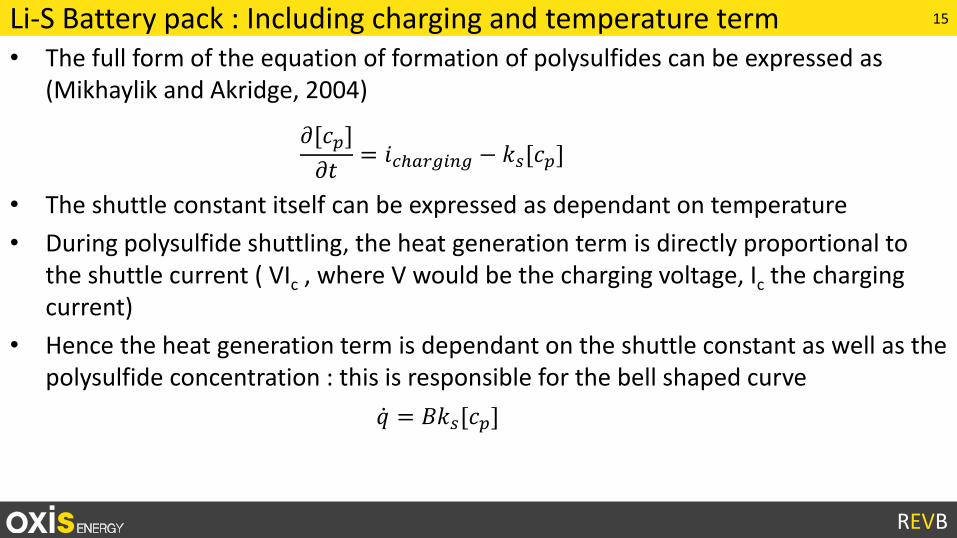
Li-S Battery pack : Including charging and temperature term• The full form of the equation of formation of polysulfides can be expressed as
(Mikhaylik and Akridge, 2004)
• The shuttle constant itself can be expressed as dependant on temperature
• During polysulfide shuttling, the heat generation term is directly proportional to the shuttle current ( VIc , where V would be the charging voltage, Ic the charging current)
• Hence the heat generation term is dependant on the shuttle constant as well as the polysulfide concentration : this is responsible for the bell shaped curve
𝜕[𝑐𝑝]
𝜕𝑡= 𝑖𝑐ℎ𝑎𝑟𝑔𝑖𝑛𝑔 − 𝑘𝑠[𝑐𝑝]
𝑞 = 𝐵𝑘𝑠[𝑐𝑝]
16
REVB
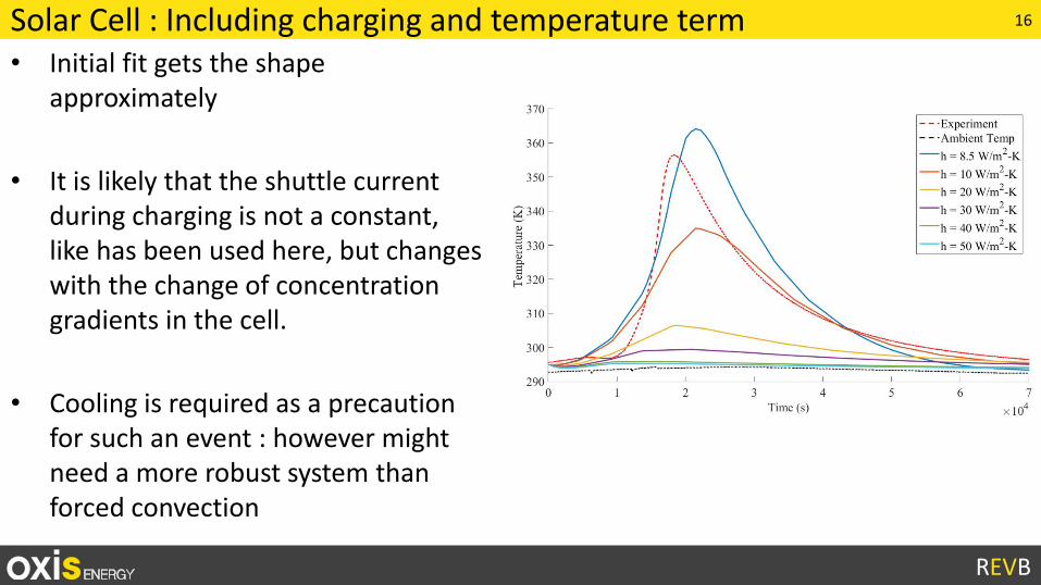
Solar Cell : Including charging and temperature term• Initial fit gets the shape
approximately
• It is likely that the shuttle current during charging is not a constant, like has been used here, but changes with the change of concentration gradients in the cell.
• Cooling is required as a precaution for such an event : however might need a more robust system than forced convection
17
REVB
Outline : From micro to macro• Cell Design : Weld resistance
• Battery Pack : Polysulfide shuttle and thermal runaway
• Pack Integration : Laminar Flow
18
REVB
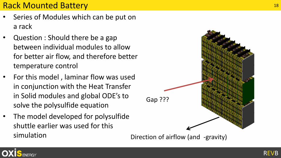
Rack Mounted Battery• Series of Modules which can be put on
a rack
• Question : Should there be a gap between individual modules to allow for better air flow, and therefore better temperature control
• For this model , laminar flow was used in conjunction with the Heat Transfer in Solid modules and global ODE’s to solve the polysulfide equation
• The model developed for polysulfide shuttle earlier was used for this simulation
Gap ???
Direction of airflow (and -gravity)
19
REVB
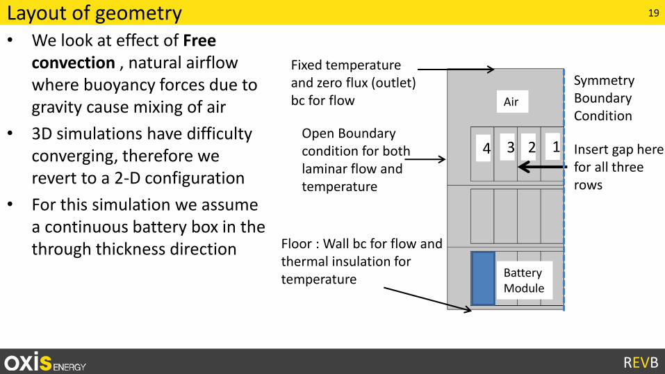
Layout of geometry• We look at effect of Free
convection , natural airflow where buoyancy forces due to gravity cause mixing of air
• 3D simulations have difficulty converging, therefore we revert to a 2-D configuration
• For this simulation we assume a continuous battery box in the through thickness direction
Insert gap here for all three rows
Fixed temperature and zero flux (outlet) bc for flow
Open Boundary condition for both laminar flow and temperature
Floor : Wall bc for flow and thermal insulation for temperature
Symmetry Boundary Condition
Battery Module
Air
1234
20
REVB
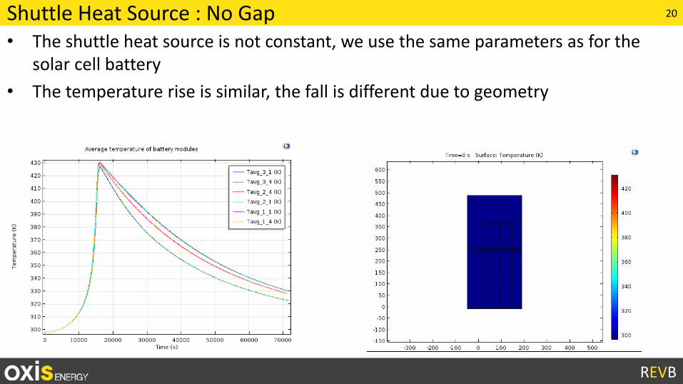
Shuttle Heat Source : No Gap• The shuttle heat source is not constant, we use the same parameters as for the
solar cell battery
• The temperature rise is similar, the fall is different due to geometry
21
REVB
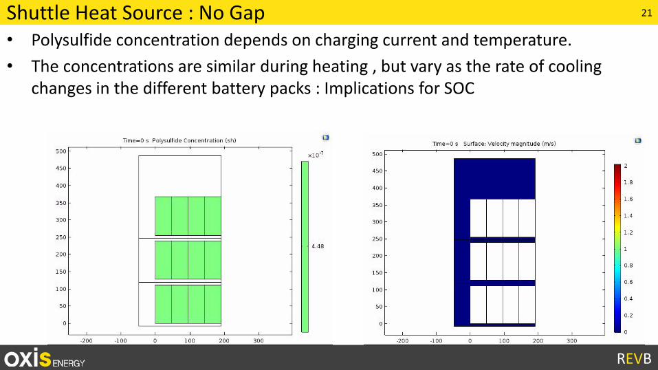
Shuttle Heat Source : No Gap• Polysulfide concentration depends on charging current and temperature.
• The concentrations are similar during heating , but vary as the rate of cooling changes in the different battery packs : Implications for SOC
22
REVB
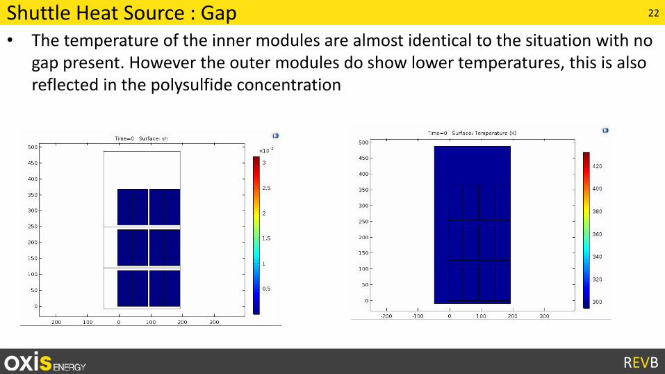
Shuttle Heat Source : Gap• The temperature of the inner modules are almost identical to the situation with no
gap present. However the outer modules do show lower temperatures, this is also reflected in the polysulfide concentration
23
REVB
Summary• Lithium sulfur is a new and exciting system for energy storage
• Along with modelling the electro-chemistry, issues related to scaling up and commercialising this technology need to be addressed e.g. Thermal issues
• Modelling is a good way to expedite this process and catch up to where lithium ion is relatively rapidly
• COMSOL is well suited for this as the multiphysics nature of the package allows for coupling several different phenomena simultaneously
• Weld resistance as of now is not an issue with OXIS cells
• Polysulfide shuttle is a serious issue and a combined approach of better design and cooling is required in order to mitigate its effects
24
REVB
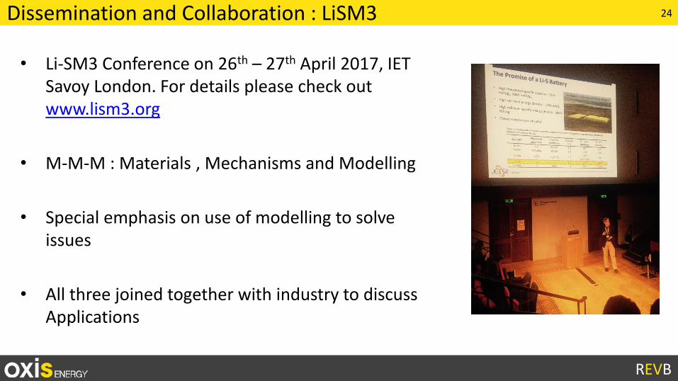
Dissemination and Collaboration : LiSM3
• Li-SM3 Conference on 26th – 27th April 2017, IET Savoy London. For details please check out www.lism3.org
• M-M-M : Materials , Mechanisms and Modelling
• Special emphasis on use of modelling to solve issues
• All three joined together with industry to discuss Applications
25
REVB
Thank You• The REVB Team
– Dr Geraint Minton
– Dr Sylwia Walus
– Dr Mark Wild
– Tom Cleaver
– Dr Peter Kovacik
• R&D, OXIS– Dr Laura O’Neill
– Dr David Ainsworth
• Imperial College– Dr Greg Offer
• Cranfield University– Dr Daniel Auger
• Ricardo
26
REVB
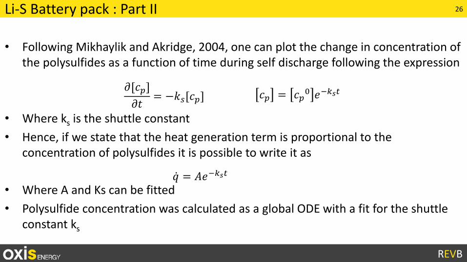
Li-S Battery pack : Part II
• Following Mikhaylik and Akridge, 2004, one can plot the change in concentration of the polysulfides as a function of time during self discharge following the expression
• Where ks is the shuttle constant
• Hence, if we state that the heat generation term is proportional to the concentration of polysulfides it is possible to write it as
• Where A and Ks can be fitted
• Polysulfide concentration was calculated as a global ODE with a fit for the shuttle constant ks
𝜕[𝑐𝑝]
𝜕𝑡= −𝑘𝑠[𝑐𝑝] 𝑐𝑝 = 𝑐𝑝
0 𝑒−𝑘𝑠𝑡
𝑞 = 𝐴𝑒−𝑘𝑠𝑡
27
REVB
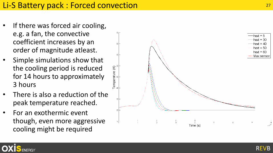
Li-S Battery pack : Forced convection
• If there was forced air cooling, e.g. a fan, the convective coefficient increases by an order of magnitude atleast.
• Simple simulations show that the cooling period is reduced for 14 hours to approximately 3 hours
• There is also a reduction of the peak temperature reached.
• For an exothermic event though, even more aggressive cooling might be required