THERMAL COMFORT AND HVAC MULTI PARAMETER MEASUREMENT PROBE 2300 AHTS … · THERMAL COMFORT AND...
36
operating instructions 3 FUNCTION PROBE THERMAL COMFORT AND HVAC MULTI PARAMETER MEASUREMENT PROBE 2300 AHTS GrayWolf Sensing Solutions advanced environmental measurements www .W olfSense.com MAN 2300AHTS Issue: 11 2004
-
Upload
nguyendiep -
Category
Documents
-
view
218 -
download
2
Transcript of THERMAL COMFORT AND HVAC MULTI PARAMETER MEASUREMENT PROBE 2300 AHTS … · THERMAL COMFORT AND...
oper
atin
g in
stru
ctio
ns3 FUNCTION PROBE
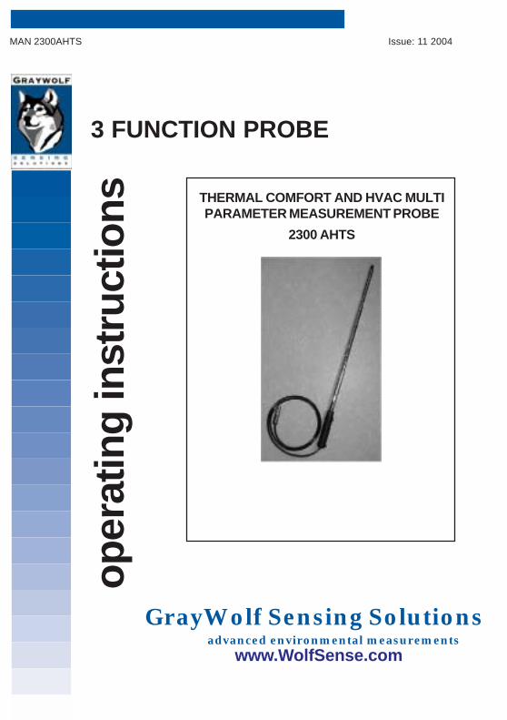
THERMAL COMFORT AND HVAC MULTIPARAMETER MEASUREMENT PROBE
2300 AHTS
GrayWolf Sensing Solutions advanced environmental measurements
www.WolfSense.com
MAN 2300AHTS Issue: 11 2004

2
MAN 2300AHTS Issue: 11 2004
Every effort has been made to ensure the accuracy in thecontents of our documents, however, GrayWolf can assumeno responsibility for any errors or omissions in our documentsor their consequences.
GrayWolf would greatly appreciate being informed of anyerrors or omissions that may be found in the contents of anyof our documents and to this end we include the followingform for you to photocopy, complete and return to us so thatwe may take the appropriate action.
HELP US TO HELP YOU

3
MAN 2300AHTS Issue: 11 2004
I suggest the following corrections/changes be made to:Chapter ........... Section ...........
Marked up copies attached (as appropriate): Yes / No
Please inform me of the outcome of this change: Yes / No
For Marketing Communications, GrayWolf:
Actioned By: Date:
Response: Date:
From :
Address :
Tel :Fax :email :
HELP US TO HELP YOU
To: Marketing Communications,GrayWolf Sensing Solutions12 Cambridge DrTrumbull, CT 06611USA
Tel : 1-203-416-0005Fax : 1-203-416-0002email : [email protected]

4
MAN 2300AHTS Issue: 11 2004
COPYRIGHT
This publication contains information partly derived fromproprietary data of GrayWolf Sensing Solutions. The expresspurpose of this information is to assist in the operation andmaintenance of the instrument described herein. The publicationof this information does not convey any right to reproduce or usethe information for any purpose other than in the operation ormaintenance of the equipment described herein.
GrayWolf shall not be liable for any incidental or consequentialdamages in connection with any deletions, errors or omissions inthis Manual.
WARRANTY
GrayWolf warrants each SURVEYOR/ZEPHYR instrument to befree from any defects in workmanship, materials and componentsfor one year from the date of purchase. Any SURVEYOR/ZEPHYR instrument found to be defective by GrayWolf within thewarranty period will be repaired (or replaced at GrayWolf'sdiscretion), providing that the product is returned, shippingprepaid, to GrayWolf or an authorized GrayWolf distributor.
SURVEYOR/ZEPHYR instrument failure must not haveoccurred as a result of operation of the instrument other than inaccordance with the instructions furnished with the instrument.
This warranty does not apply if the instrument has beensubjected to unusual physical or electrical stress or on whichthe original identification marks have been removed or altered.
This warranty will not apply if adjustments, repair or partsreplacement is required because of accident, hazard, misuse,transportation or causes other then ordinary use; in which caserepair will be charged at normal rates. An estimate will besubmitted before repair work starts and a purchase order mustbe supplied before work begins. Any out of warranty repairs arewarranted 90 days from the date of invoice. The warranty does
COPYRIGHT AND WARRANTY

5
MAN 2300AHTS Issue: 11 2004
not apply if any modifications have been made by anyone otherthan GrayWolf or an authorized distributor.
The foregoing warranty is in lieu of all other warranties, conditions,terms, undertakings and obligations implied by statute, commonlaw, custom, trade usage, course of dealing, or otherwise, all ofwhich are hereby excluded to the fullest extent permitted by law.This warranty does not affect the statutory rights of a consumer. Insuch transactions, the rights and obligations of the Buyer andSeller shall be determined by statute.
GrayWolf shall have no liability or obligations under this warrantyother than to remedy breaches thereof by the provision ofmaterials and services within a reasonable time and withoutcharge (or, where appropriate In accordance with the above atnormal rates). If GrayWolf shall fail to comply with suchobligations its liability for such failure shall be limited to a sumequal to the price. The foregoing states the entire liability ofGrayWolf, whether in contract or in tort, for defects in theinstrument notified to it after the date of purchase order otherthan liability arising where loss of damage to any property orinjury to or death of any person is caused by any negligent act oromissions or wilful misconduct of GrayWolf, its employees,agents or subcontractors or by any defect in the design orworkmanship of the instrument.
Save as otherwise stated, in no circumstances shall GrayWolf beliable in contract or in tort or otherwise for any direct incidental orconsequential loss suffered by the purchaser or their agents.
GrayWolf does not give any warranty that the instrument is fit for anyparticular purpose unless the purpose is specifically advised toGrayWolf in writing and GrayWolf confirms in writing that theinstrument can fulfil that particular purpose. Representations andwarranties which are inconsistent with the terns of this warranty arenot valid unless approved in writing by an officer of GrayWolf.Contact GrayWolf directly if there are any questions about thiswarranty.
COPYRIGHT AND WARRANTY

6
MAN 2300AHTS Issue: 11 2004

7
MAN 2300AHTS Issue: 11 2004
CONTENTS
Section Page
1. INTRODUCTION 9
1.1 The GrayWolf Thermal Comfort & HVAC MultiParameter Measurement Probe 9
2. AIR COMFORT OF THE OCCUPIED ZONE 11
3. AIR TEMPERATURE 13
4. RELATIVE HUMIDITY AND DEWPOINT 15
5. AIR SPEED 19
5.1 Introduction 195.2 The Anemometer 195.3 Traversing a Duct 21
6. PROBE MAINTENANCE 23
7. SENSOR CALIBRATION 25
7.1 Hot Wire Anemometer and Pt100 257.2 Humidity Sensor 257.3 Humidity Sensor Calibration References 257.4 Zero Calibration References 267.5 Salt Solution Calibration References 277.6 Calibration Procedure 30
8. SERVICE 33
9. SPECIFICATION 35

8
MAN 2300AHTS Issue: 11 2004
CONTENTS
TABLES
Table Page
1 Salt Solution Accessory Kits 262 %RH of Saturated Binary Salts at
Different Temperatures 293 Specification 35
FIGURES
Figure Page
1 Traversing a Duct to Calculate Volume Flow 22
9
MAN 2300AHTS Issue: 11 2004
1. INTRODUCTION
1.1 THE GRAYWOLF THERMAL COMFORT ANDHVAC MULTI PARAMETER MEASUREMENTPROBE
The 2300AHTS is an extendable three sensor probe for usewith the GrayWolf Surveyor or Zephyr II range ofmeasurement display instruments. It monitors the three mainparameters for human comfort in occupied spaces, namelyair temperature, air speed (or drafts) and relative humidity.The probe is ideal for use by Heating Ventilation and AirConditioning (HVAC) engineers when setting up andcommissioning HVAC systems. Two important additionalparameters, dew point and volume flow rate, areautomatically calculated by the Surveyor or Zephyrinstrument from the probe data, and are displayed with themain probe parameters.
The telescopic sections allow the airspeed, relative humidityand temperature sensors to be placed in 'hard to reach' ornormally inaccessible places, e.g inside ducts. The2300AHTS is described as a 'smart probe' as it contains itsown linearization and calibration data, factory and user-setalarm levels, and serial number. This means that the probecan be transferred to another Surveyor or Zephyr instrumentwithout the need for time-consuming re-calibration or re-setting measurement units and alarm levels.
The probe is easily attached to the Surveyor or Zephyr IIinstrument by means of the two integral probe modellingclips on the probe handle, thus enabling it to be held in onehand when making measurements. The fast response, highprecision, accurate sensors in the probe make it ideal forquick spot checks, high accuracy continuous monitoring, ordata logging (not Zephyr II).

10
MAN 2300AHTS Issue: 11 2004
Before using your multi parameter probe, please read theoperating manual supplied with the Surveyor or Zephyrinstrument. These manuals explain how to use theinstruments correctly. They also explain how to program theinstrument, and how to set it up to take measurements andlog data.
1. INTRODUCTION

11
MAN 2300AHTS Issue: 11 2004
For satisfactory indoor air quality, relative humidity (RH) mustbe maintained between 30% and 60% RH (i.e. 1.7 to 16.7oCdewpoint, or 35 to 62oF dewpoint) and temperature between20 and 27°C (68 to 80oF), with local ventilation typicallybetween 10 and 15 litres/person/second (21.28 and 31.92 ft3/min).
The ideal temperature depends on season, airflow anddewpoint temperature. The air change rate can be measuredto give an accuracy of +/- 20%; careful measurements cangive +/-10%. Note that air change regulations vary not onlyfrom country to country but also with application. Publishedspecifications depend on whether the occupied zone is anoffice, factory, auditorium or other type of space: sometimesdefining air change rate in terms of changes per occupantand at other times defining it in terms of air change rate perunit floor area.
2. AIR COMFORT OF THE OCCUPIED ZONE

12
MAN 2300AHTS Issue: 11 2004
13
MAN 2300AHTS Issue: 11 2004
Air temperature is the most important thermal comfortmeasurement. Not only does temperature need to becontrolled tightly (typically between 20 and 27oC, 68 and 80oF,depending on season), but sudden temperature changes(more than 2oF per hour) cause discomfort to occupants.Temperature also affects other comfort parameters such asrelative humidity, which is very sensitive to ambienttemperature.
To reduce radiant error when measuring air temperature, thesensor in your probe is as small as possible. This is becausethe convective heat transfer coefficient increases as sizedecreases, while the radiant heat transfer coefficient isconstant.
By monitoring temperature for a week, you can follow thebuilding's air handling behavior:
! Check insulation efficiency by monitoring thetemperature drop when the heating is turned off.
! Check cycling around the setpoint by monitoring thethermostat temperature.
! Monitor the temperature set-back thermostat.
! Check for temperature variation in workplaces andoffices beyond that which would normally be expectedwhen these areas have been vacated by monitoringtemperature during lunch breaks, Saturday workingand overtime working.
3. AIR TEMPERATURE
14
MAN 2300AHTS Issue: 11 2004
The quantity of outdoor air being added to the mixed air iscalculated using the following formula:
Air mixture (%) = 100 x (Ts-Tr)/(To-Tr)
Where: Ts = supply/mixed air temperatureTr = return air temperatureTo = outside air temperature
The 2300AHTS probe includes a Pt100 temperature sensorfor accurate air temperature measurements. The sensorstabilises rapidly when measuring in ducts or where there isforced air movement, but in an office, where airspeed is verylow, the probe must be gently moved around to obtain rapidstabilization of the sensor.
3. AIR TEMPERATURE

15
MAN 2300AHTS Issue: 11 2004
4. RELATIVE HUMIDITY AND DEWPOINT
Both relative humidity (RH) and absolute humidity (ordewpoint, the temperature at which moisture in the air startsto condense onto a smooth surface) affect the comfort ofpeople and the growth of micro-organisms, especially in ductsystems. Additonally formaldehyde emissions increase whenboth RH and temperature increase. Most viruses grow bestin low temperature high humidity environments, althoughlipid viruses prefer low humidity environments.
Maintaining low RH is not the answer to all problems sinceeye and skin irritation, along with respiratory tract problems,can occur if the humidity is too low. Dust can also be aserious problem in low humidity environments. Relativehumidity limits are therefore usually specified as between 30and 60%.
Relative humidity increases with the number of occupantspresent, and decreases with increasing temperature;absolute humidity also changes with the number ofoccupants in a zone, but is independent of changingtemperature.
The 2300AHTS probe measures relative humidity (RH) andtemperature with a fast response thin film polymercapacitive sensor and a fast response Pt100 sensorrespectively.
RH is sensitive to ambient temperature, so the humiditysensor must be thermally stable before an accurate humidityreading can be made.
The thin film polymer capacitive sensor used by the probeabsorbs and transpires water rapidly, so that its capacitancechanges rapidly in response to changes in RH. Thesesensors provide an accurate and fast response over verywide ranges. The 2300AHTS RH sensor is accurate to +/-2% from 0 to 75% RH and +/- 3% from 75 to 100% RH.

16
MAN 2300AHTS Issue: 11 2004
4. RELATIVE HUMIDITY AND DEWPOINT
The Pt100 resistance temperature detector (RTD) isincorporated in the probe sensing head alongside thehumidity sensor. This monitors the ambient temperature ofthe humidity sensor allowing automatic calculation ofdewpoint (absolute humidity) by the Surveyor or Zephyr IIinstruments. The instrument displays humidity as % RH andthe corresponding dewpoint temperature in oC, oF or K.Additonally, the ambient air temperature is displayed in oC, oFor K.
Since humidity measurement requires the sensor to absorb atrace amount of water, the sensor can also absorb otherchemicals in the atmosphere. These may alter the probe'scalibration or, in extreme cases, destroy the sensor. A simplerule is: if you can breath comfortably in the measuringenvironment, then the probe should operate accurately.However, if their concentration is high enough, the followingchemicals are capable of destroying the sensor:
a. fungicides and bactericides,b. organic catalysts and surfactants,c. nitrous oxides,d. chlorine (at high temperatures and high %RH),e. sulfur dioxide (at high temperatures and high %RH),f. ketones and acetones (at high temperatures),g. ethylene oxide.
Certain other chemicals (ammonia, alcohol, formaldehyde)can cause the sensor to give a false high %RH reading.
Few, if any, of the above will be found in standard IAQ orHVAC environments; they are only likely to be met in specialapplications.

17
MAN 2300AHTS Issue: 11 2004
4. RELATIVE HUMIDITY AND DEWPOINT
The above information regarding chemical pollution isprovided only as a guide. If you are concerned about thechemical environment you should contact GrayWolf or yourdistributor for advice. Specify the temperature andapproximate humidity, along with the concentrations andtypes of chemicals present.
The following points provide general guidance for thesuccessful use of the 2300AHTS probe:
! The humidity and temperature sensor will respondmore rapidly if there is some air flow. In still air, gentlywave the probe from side to side.
! Avoid contaminating the humidity sensor with cigarettesmoke. The tar residue can alter the calibration.
! Relative humidity depends on temperature and,typically, will change by 3% for a 1oC (2oF) change intemperature. Always allow sufficient time for thesensor to reach thermal equilibrium when checkingrooms at different temperatures. Note that whenentering a colder room, the initial reading will be low;and for a warmer room it will be high.
! The usual lower temperature limit for humiditymeasurements is 0oC (32oF), but measurements atsub-zero temperatures can be made if certaincorrections are applied to the displayed %RH reading.The displayed RH should be increased by 1% of thereading for each1oC below zero. For example, at –5oC (23oF) thereading should be multiplied by 1.05. Calculateddewpoint readings are not affected.

18
MAN 2300AHTS Issue: 11 2004

19
MAN 2300AHTS Issue: 11 2004
5. AIRSPEED
WARNING
The sensor in this product operates at 180oC aboveambient temperature. Do not use this probe where itcould present a possible safety hazard. It is the user'sresponsibility to ensure that equipment meets all relevantsafety regulations. If in doubt contact GrayWolf.
Do not touch the thermistor sensor – it is very delicate.Avoid mechanical shock to the probe. Do not use theprobe if the sensing head is wet. Take care not to pinchthe protective cap when removing it.
5.1 INTRODUCTION
A fundamental requirement for air comfort is that there issufficient ventilation for either the number of people or thenumber of square metres (or square feet) in the occupancyzone. The ventilation rate can be expressed either as cubic feet/minute/person (or litres/sec/person) or cf/min/ft2 (or l/sec/m2).
Since air speed velocities normally fluctuate, the mean airspeed value in an occupied zone should be measured over asingle period of time (typically 3 minutes). Fluctuations inairspeed, with frequency up to 1 Hz, also significantly affecthuman comfort.
5.2 THE ANEMOMETER
The 2300AHTS probe uses a hot wire thermistor to measureair speed. A small thermistor is heated to a constant temperature ofapproximately 180oC above ambient temperature. The passing aircools the thermistor and electronic circuitry monitors theadditional power required to maintain the thermistortemperature. The additional power signal is thus a measureof the air speed. A second, unheated, thermistor provides

20
MAN 2300AHTS Issue: 11 2004
compensation to correct for changes in ambient temperature.
Airspeed is a vital parameter in production areas,environmental studies, ventilation system, air quality auditsand refrigeration.The hotwire anemometer is fast and very sensitive, making itsuitable for measuring turbulence and local ventilation aspart of an indoor air quality audit.
The hotwire anemometer on the 2300AHTS probe can becomfortably held in one hand when used to detect draughts,check fume hoods or measure air flow and air change ratesin offices and work places. The telescopic wand allows thesensors to reach up to 745mm from the handle. It must beremembered that a hotwire anemometer is not suitable foruse where the air flow ambient temperature is liable toexceed 50oC (122oF) or fall below 0oC (32oF).
The user instrument displays the airspeed from 0–12 m/s insteps of 0.1 m/s or 0-2500 ft/min in steps of 22 ft/ min.
Remember to remove the protective dust cap carefullybefore use, and to replace it after use.
To optimise the accuracy of your airspeed measurement, theprobe must be oriented so that the blue arrows on either sideof the sensing head point in the same direction as theairflow.
For making measurements in air flows with changingdirection, it is permissible to unscrew and carefully removethe black oval arch moulding protecting the sensor. Extremecare must be taken as the sensor will now be totally exposedand susceptible to damage.
Note: Probes are calibrated with the sensor arch firmlyscrewed in place. The calibration may shift by 3% (ofthe reading) when the arch is removed.
5. AIRSPEED

21
MAN 2300AHTS Issue: 11 2004
When measuring airspeed in the rain, be aware that the forceof a falling raindrop can damage the sensor.
5.3 TRAVERSING A DUCT
The hotwire anemometer is ideal for traversing air ducts orfor determining face velocity at registers or filters whenmeasuring volume flow rate. By entering the duct dimensionsinto the Surveyor or Zephyr instrument a display of volumeflow rate (VFR) is given. An averaging facility is also availableon the Zephyr II, Zephyr II+ and IAQ Surveyor Pro.
To determine the airflow through a circular or rectangularduct correctly, the air velocity must be measured at severalpoints. Use some tape or a black felt tip pen to mark thecorrect measurement positions when traversing the duct.
1 If there is significant swirl in the air stream you maywish to use flow straighteners, located upstream ofthe measurement by at least five times the dustdiameter.
2 To obtain an approximate volume flow measurementthat is normally accurate to 5%: measure the airspeedat the center, then multiply by 0.9 to get an averageairspeed before converting to volumetric flow.
Alternatively, measure at 10% (from the edge) of theduct diameter: this should be the average velocity inducts with fully developed flow.
You can also measure to an accuracy of 2% bymeasuring each grid point and then averaging, beforecalculating the air volume.
3 You can also measure volumetric flow directly byprogramming your instrument with your duct crosssection. See the manual supplied with the instrument.
5. AIRSPEED

22
MAN 2300AHTS Issue: 11 2004
5. AIRSPEED
TRAVERSING A DUCT
Figure 1 Traversing a duct to calculate volume flow

23
MAN 2300AHTS Issue: 11 2004
The probe requires no routine maintenance other thanto ensure that it is clean and dry after use. Ensure thatthe telescopic tube is closed up and the hotwire sensorprotective cap is fitted, when the probe is not in use.
The most common cause of probe failure is accidentaldamage to one of the sensors, or extreme chemicalpollution of the humidity sensor. In these cases theprobe must be returned to GrayWolf or one of theirservice agents for repair.
6. PROBE MAINTENANCE

24
MAN 2300AHTS Issue: 11 2004

25
MAN 2300AHTS Issue: 11 2004
7.1 HOTWIRE ANEMOMETER AND Pt100
There is no fixed calibration period for the hotwireanemometer, since the measuring environment and theamount of usage both affect the need to recalibrate. Forexample, continous usage at high airspeeds (at the upperend of the specified range) will cause earlier loss ofcalibration accuracy. Hotwire anemometers require a windtunnel to calibrate them and so must be returned to GrayWolfor one of their service agents for recalibration.
The Pt100 Platinum temperature sensor is mechanically andelectrically stable and resistant to contamination or oxidation.As such, it does not require routine calibration.
7.2 HUMIDITY SENSOR
Calibration of the humidity sensor at 6-month intervals shouldusually be adequate for normal ambient room temperaturemeasurements. In high humidity / temperature applications,or in polluted or smoky environments, more frequentcalibration is recommended, up to 2 or 3 monthly intervalsdepending on the severity of the conditions. Humiditycalibration is available as an accessory kit.
7.3 HUMIDITY SENSOR CALIBRATION REFERENCES
Calibration consists of a full 2-point adjustment, referred toas zero (low cal) and gain (high cal). See the sensorcalibration section in the instrument manual. Normally, thesensor retains its accuracy over long periods and the readingdisplayed following calibration should not change significantlyfrom the factory calibration settings. If they do, it couldindicate a contaminated sensor; the probe must then bereturned to GrayWolf or one of their service agents for repair.
Calibration requires the exposure of the sensor to a molecularsieve desiccant (0%) or low humidity salt solution for the zero
7. SENSOR CALIBRATION

26
MAN 2300AHTS Issue: 11 2004
(Lo Cal) setting, and to a higher humidity salt solution(sodium chloride) for the span (Hi Cal) setting. Twocalibration jar assemblies are therefore required, containingrespectively the desiccant or 'low' salt solution and the highsalt solution. A suitable calibration kit containing desiccantand sodium chloride salt for 0% and 75% RH calibration canbe purchased from GrayWolf. These %RH figures are for theprescribed calibration temperature of 24.5 to 25.5oC (76 to78oF). If the temperature is outside this range, an appropriatecorrection must be made to the reference %RH (see table 2).Accessory kits containing high purity salts for calibration atvarious RH levels are also available (see table 1).
Table 1 Salt solution accessory kits
Accessory Part No. Salt NominalReference %RH
HC11 P144 HC11/00 Lithium Chloride 11%HC33 P144 HC33/00 Magnesium Chloride 33%HC53 P144 HC53/00 Magnesium Nitrate 53%HC75 P144 HC75/00 Sodium Chloride 75%HC85 P144 HC85/00 Potassium Chloride 85%HC97 P144 HC97/00 Potassium Sulphate 97%
7.4 ZERO CALIBRATION REFERENCE
The molecular sieve desiccant used as a zero RH referenceabsorbs any water in the air to produce a very dryatmosphere at any temperature. This will maintain a relativehumidity of <5% as long as its container jar is well sealed,and can absorb up to 5% of its own weight before starting tolose effectiveness. A quick drying will rejuvenate thedesiccant, giving the reference a typical life of three years ormore. The jar must be sealed with its rubber stopper when notin use.
7. SENSOR CALIBRATION

27
MAN 2300AHTS Issue: 11 2004
If it is found that the molecular sieve dessiccant cannotmaintain 0% RH (if, for instance, the jar has been leftunsealed), it can be rejuvenated by drying it at 250/300oC(480/570oF) for three hours in an oven and then immediatelytransferring it to its jar and sealing the jar. Allow the desiccantto cool in the jar before use.
7.5 SALT SOLUTION CALIBRATION REFERENCES
The sodium chloride salt supplied with the calibration kitallows you to re-calibrate the probe high cal at (nominally)75%RH. However if the %RH normally measured is alwaysat a much higher or lower level, then, instead, use one of theother high purity salts available from GrayWolf (see table1above). These will provide a %RH closer to your particularapplication. Table 2 lists the alternative salts that may be used,with details of the salt to distilled water proportion for thecorrect solution, and the variation in the resultant RH fordifferent ambient temperatures.
To prepare the salt solution, measure the correct volume ofdistilled water (see table 2) into the calibration jar. Slowlypour in the correct weight of salt while stirring with a glass orplastic rod. Stir until there is approximately 2 mm (1/10 in)depth of water on top of the salt slush after settling. This willensure the recommended condition of a thin layer ofsaturated water above a salt precipitate. Remove excesswater with the syringe and then seal the jar.
Take care when preparing Lithium Chloride solutions asheat is generated when the Lithium Chloride is added tothe water. Add the salt slowly and stir thoroughly.
Allow the salt solution to stabilize for 24 hours at a constanttemperature before attempting to calibrate the probe. Tominimise temperature changes, do not remove the jar from
7. SENSOR CALIBRATION

28
MAN 2300AHTS Issue: 11 2004
the packing case.
The accuracy of the salt reference depends on the specificsalt and is typically +/- 2%RH, but can be as low as +/- 20%if the salt is icorrectly prepared. Certain precautions shouldbe followed to ensure an accurate salt reference:
! The salt solution should be kept at a constanttemperature (<1oC/hr variation) during stabilization andcalibration.
! Once the salt solution is prepared, keep it at aconstant temperature (ideally the same as thecalibration room) so that it is always ready for use.The 24 hour stabilization period is necessary onlywhen first preparing the solution.
! Excessive temperature cycling of the salt solution willform crystals and the solution may not remainsaturated. If it has been subjected to an excessivelyhigh temperature, prepare a fresh solution.
! Always ensure that the calibration jar is sealed with itsrubber stopper, when not in use.
! Before using sodium chloride solution, check that it hasnot lost so much water that it has become dehydrated.
! When using lithium chloride solution, ensure that itstemperature never falls below 18oC (64oF); otherwise itmust be replaced.
! Salt solutions have a finite life. It is recommended thathigh RH solutions (>70%RH) are renewed at monthlyintervals, and low RH solutions (<70% RH) at twomonthly intervals.
A humidity sensor cannot be calibrated quickly. First, thecalibration room temperature must be stable, ideally at
7. SENSOR CALIBRATION

29
MAN 2300AHTS Issue: 11 2004
25 +/- 0.5oC (77 +/- 1oF); then, at least 24 hours must beallowed after mixing fresh salts for the salt reference tostabilise; the probe must then be allowed to stabilise, withoutpower applied; (if power is applied during this period the hotwire will heat the salt solution); finally, allow at least another 2hours to calibrate the probe.
Calibration of the 2300AHTS is carried out with the probeconnected to a Surveyor or Zephyr instrument running in itschannel calibration mode.
When calibration is complete the instrument writes thecalibration information to the 2300AHTS probe memory. Theprobe can subsequently be connected to any Surveyor orZephyr instrument and maintain its calibration settings.
7.6 CALIBRATION PROCEDURE
7. SENSOR CALIBRATION
Table 2 %RH of saturated binary salts atdifferent temperatures
Solution Temperature
Salt Salt Water 10 C 15 C 20 C 25 C 30 C 35 C 40 C 45 C(g) (ml) 50 F 59 F 68 F 77 F 86 F 95 F 104 F 113 F
Lithium Chloride(anhydrous) 80 36 - - 11.3 11.3 11.3 11.3 11.2 11.2
Magnesium Chloride(hexahydrate) 95 10 33.5 33.3 33.1 32.8 32.4 32.1 31.6 31.1
Magnesium Nitrate(hexahydrate) 100 12 57.4 55.9 54.4 52.9 51.4 49.9 48.4 46.9
Sodium Chloride 100 28 75.7 75.6 75.5 75.3 75.1 74.9 74.7 74.5

30
MAN 2300AHTS Issue: 11 2004
Refer to the instrument manual for details of running theprobe calibration mode.
! Connect the 2300AHTS probe to the instrument.Ensure that the instrument is switched off at thismoment in time.
! Fit the probe into the zero reference calibration jar andallow for the probe sensor to stabilise for 60 minutes.
! Switch the instrument on and via the menu systementer calibration mode.
! Check that the Low Cal and High Cal points arecorrect for the salt solutions being used, taking intoconsideration any variations in ambient temperature.If necessary, adjust the calibration points in the DoStandard Cal Setup screen.
! Proceed with the Low Cal (zero) calibration on theinstrument.
! Remove the probe from the calibration jar and allow itto stabilize in ambient air for 10 minutes.
! Switch the instrument off.
! Fit the probe into the gain reference calibration jar(75.3%RH salt solution) and allow the probe sensor tostabilize for 60 minutes.
Caution
7. SENSOR CALIBRATION
31
MAN 2300AHTS Issue: 11 2004
Do not expose the 2300AHTS probe to the sodiumchloride solution for more than 75 minutes as thismay cause the sensor to saturate, indicated by thereading increasing continuously instead ofstabilizing.
! Switch the instrument on and proceed with the gaincalibration on the instrument.
! Remove the probe from the calibration jar and switchoff the instrument.
7. SENSOR CALIBRATION

32
MAN 2300AHTS Issue: 11 2004

33
MAN 2300AHTS Issue: 11 2004
A probe fault may manifest itself in two different ways.Firstly, the instrument may be unable to calibrate the probe.The instrument informs the user of this by displayingWARNING – PROBE FAILED TO CALIBRATE. If this occurs,please ensure that the calibration method is correct; forexample the probe is seated correctly in the calibration jar.
Secondly, a channel may display an overflow or underflowindication (3 arrows) in place of the sensor reading. Thismay indicate that the sensor is faulty, or it may be becausethe sensor is outside its specified operating range.
If the probe is being used in its correct environment, but 3arrows are still being displayed, or the probe will notcalibrate:
! Notify GrayWolf's Service Department (the address ison the back cover of this manual, the telephonenumber is on the back of the instrument) or yournearest distributor, and give full details of the problemor the required servicing, together with the probe serialnumber. You will then be given shipping instructions.
! Forward the probe as instructed with shippingprepaid. GrayWolf or your distributor will repair andcalibrate the probe, and return it, shipping prepaid.
For probe returns, please contact your nearest servicelocation for a 'Return Authorization Number' beforedespatching the probe. This procedure helps GrayWolf toprovide you with a speedy response and accurate tracking ofyour probe.
8. SERVICE

34
MAN 2300AHTS Issue: 11 2004

35
MAN 2300AHTS Issue: 11 2004
2300AHTS
Operating Temperature Range: 0oC to 50oC 32oF to 122oF
Parameter Sensor Range / Resolution Accuracy(Instrument +
Probe)
Relative PolymerHumidity Capacitor 0.0 to 98.0 %RH +/- 2%RH (<75%RH)
+/- 3%RH (>75%RH)
Dewpoint Calculated from -33.0 to +70.0oC +/- 2.0oC%RH and (-27.4 to +158.0oF) (+/- 3.6oF)
temperature (240 to 343K) +/- 2.0 K
Temperature Platinum Pt100 -26.0 to +70.0oC +/- 0.33oC(-15.0 to +158.0oF) (+/- 0.59oF)
(247 to 343K) +/- 0.33 K
Air Velocity Hotwire bead 0 to 2500 f/m +/- 3% of reading(0.00 to 12.00 m/s) at 1 f/m
Volume Calculated from air 0 to 10,000 f3/mFlow Rate velocity and duct 0 to 10,000 f3/h
dimensions 0 to 50.8 m3/sec0 to 167 m3/m
9. SPECIFICATION

MAN 2300AHTS Issue: 11 2004
GrayWolf Sensing Solutions, LLC12 Cambridge Dr.
Trumbull, CT 06611Phone: 203-416-0005
Fax: 203-416-0002
GrayWolf Sensing Solutions, LTDTuamgraney Industrial Estate
Tuamgraney, Co Clare, IrelandPhone: (353)61921736
Fax: (353)61921528
Distributor:
This publication is not intended to form the basis of a contract, and the company reserves theright to amend the design and specification of the instruments without notice.
GrayWolf Sensing Solutions advanced environmental measurements
www.WolfSense.com