
Theory of turbo machinery / Turbomaskinernas teori Dixon ... · PDF fileTheory of turbo...
27
Theory of turbo machinery / Turbomaskinernas teori Dixon, chapter 7 Centrifugal Pumps, Fans and Compressors
Transcript of Theory of turbo machinery / Turbomaskinernas teori Dixon ... · PDF fileTheory of turbo...

Theory of turbo machinery / Turbomaskinernas teori
Dixon, chapter 7
Centrifugal Pumps, Fans and Compressors
And to thy speed add wings. (MILTON, Paradise Lost.)
LTH / Kraftverksteknik / JK
Centrifugal Pumps, Fans and Compressors
• What do radial machines look like?• Swept wings or not?• Slip (deviation).• Example.
Material adopted from:
• Alvarez, Energiteknik• KSB: Selecting centrifugal pumps
LTH / Kraftverksteknik / JK
Centrifugal Pumps, Fans and Compressors
( ) 4/3
2/1
4/31
2/11
gHNQN s ==
ψφ
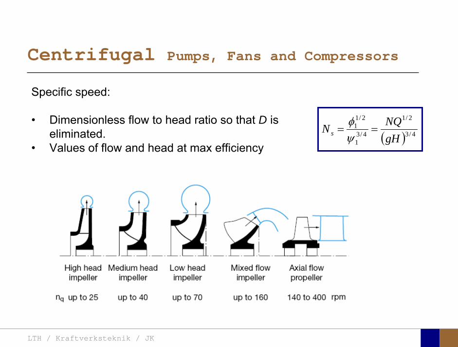
Specific speed:
• Dimensionless flow to head ratio so that D is eliminated.
• Values of flow and head at max efficiency
LTH / Kraftverksteknik / JK
Centrifugal Pumps, Fans and Compressors
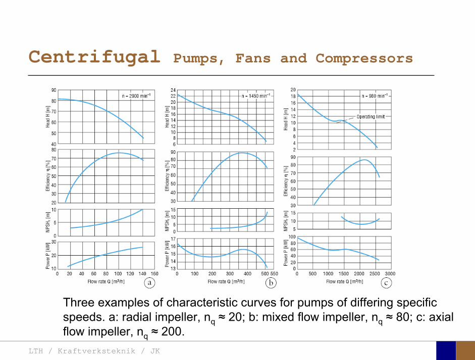
Three examples of characteristic curves for pumps of differing specificspeeds. a: radial impeller, nq ≈ 20; b: mixed flow impeller, nq ≈ 80; c: axial flow impeller, nq ≈ 200.
LTH / Kraftverksteknik / JK
Centrifugal Pumps, Fans and Compressors
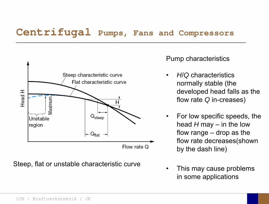
Steep, flat or unstable characteristic curve
Pump characteristics
• H/Q characteristics normally stable (the developed head falls as the flow rate Q in-creases)
• For low specific speeds, the head H may – in the lowflow range – drop as the flow rate decreases(shownby the dash line)
• This may cause problems in some applications
LTH / Kraftverksteknik / JK
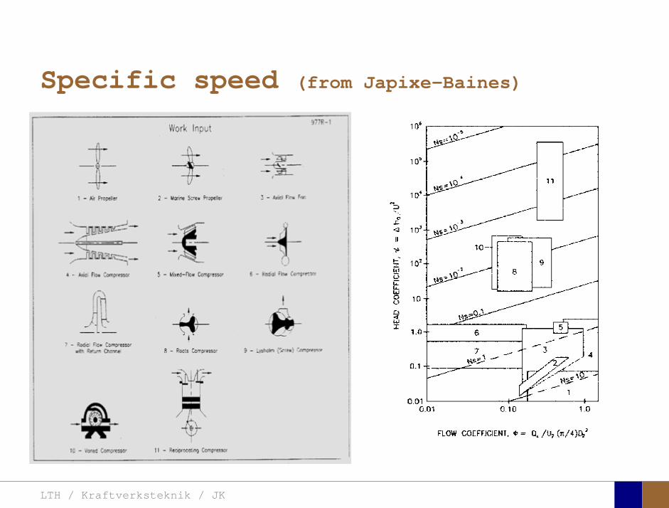
Specific speed (from Japixe-Baines)
LTH / Kraftverksteknik / JK
Centrifugal Pumps, Fans and Compressors
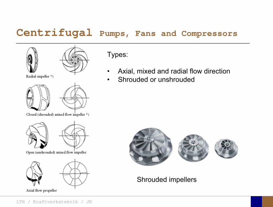
Types:
• Axial, mixed and radial flow direction• Shrouded or unshrouded
Shrouded impellers
LTH / Kraftverksteknik / JK
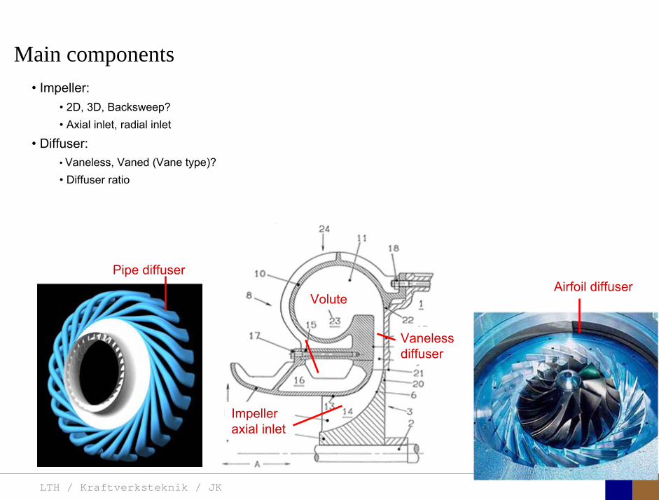
• Impeller:• 2D, 3D, Backsweep?• Axial inlet, radial inlet
• Diffuser:• Vaneless, Vaned (Vane type)? • Diffuser ratio
Volute
Vanelessdiffuser
Impeller axial inlet
Main components
Pipe diffuserAirfoil diffuser
LTH / Kraftverksteknik / JK
Centrifugal Pumps, Fans and Compressors
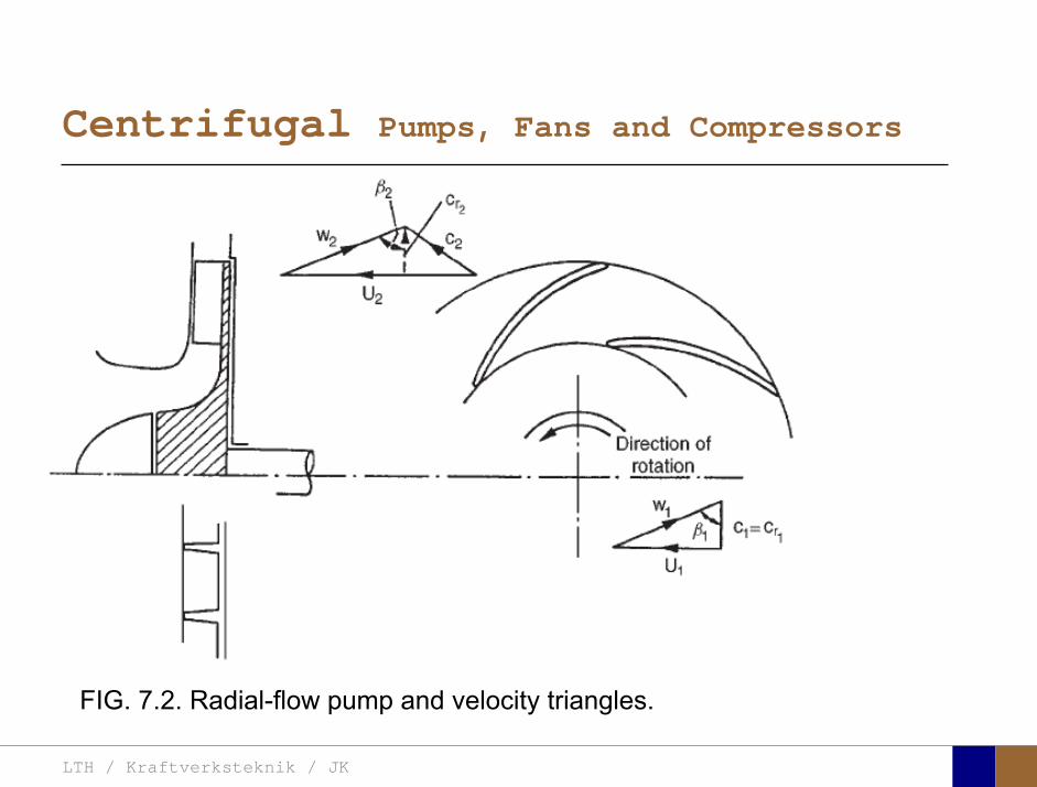
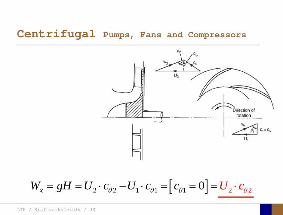
FIG. 7.2. Radial-flow pump and velocity triangles.

LTH / Kraftverksteknik / JK
Centrifugal Pumps, Fans and Compressors
FIG. 7.1. Centrifugal compressor stage and velocitydiagrams at impeller entry and exit.
321
LTH / Kraftverksteknik / JK
Centrifugal Pumps, Fans and Compressors
[ ]2 1 21 1 22 0xW gH U c U c c U cθ θθ θ= = ⋅ ⋅ = ⋅− = =
LTH / Kraftverksteknik / JK
Centrifugal Pumps, Fans and Compressors
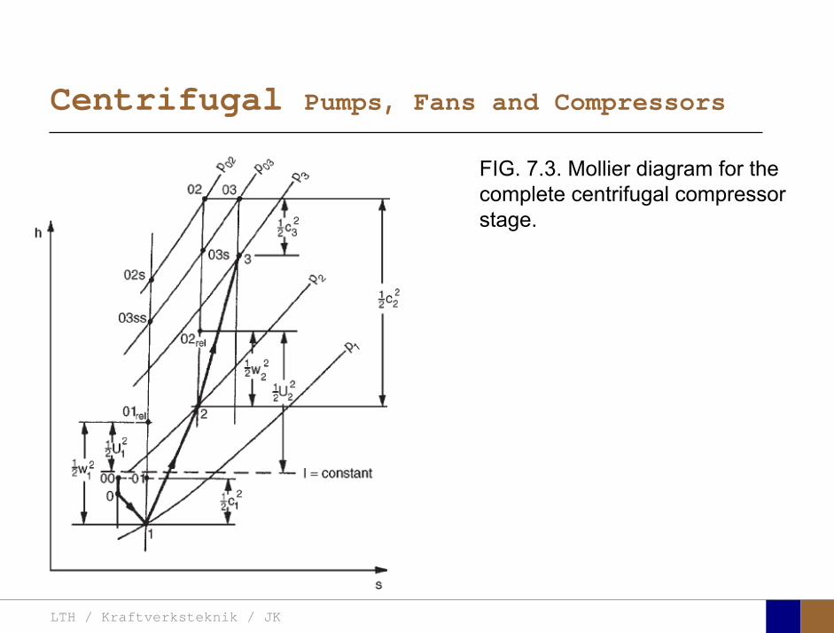
FIG. 7.3. Mollier diagram for the complete centrifugal compressorstage.
LTH / Kraftverksteknik / JK
Centrifugal Pumps, Fans and Compressors
2cθ
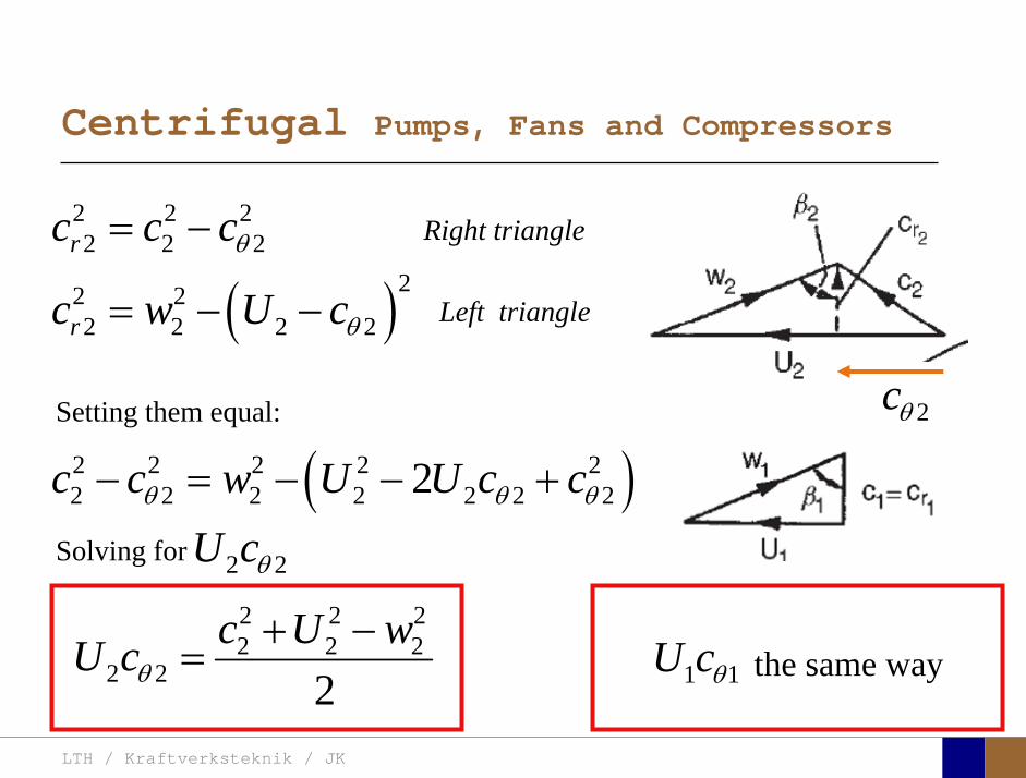
2 2 22 2 2rc c cθ= −
( )22 22 2 2 2rc w U cθ= − −
( )2 2 2 2 22 2 2 2 2 2 22c c w U U c cθ θ θ− = − − +
Solving for 2 2U c
Setting them equal:
θ
2 2 22 2 2
2 2 2c U wU cθ+ −
= the same way1 1U cθ
Right triangle
Left triangle
LTH / Kraftverksteknik / JK
Centrifugal Pumps, Fans and Compressors
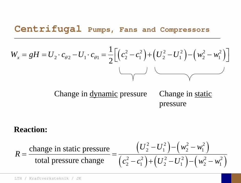
( ) ( ) ( )2 2 2 2 2 22 2 1 1 2 1 2 1 2 1
12xW gH U c U c c c U U w wθ θ⎡ ⎤= = ⋅ − ⋅ = − + − − −⎣ ⎦
Change in dynamic pressure Change in staticpressure
( ) ( )( ) ( ) ( )
2 2 2 22 1 2 1
2 2 2 2 2 22 1 2 1 2 1
change in static pressuretotal pressure change
U U w wR
c c U U w w
− − −= =
− + − − −
Reaction:
LTH / Kraftverksteknik / JK
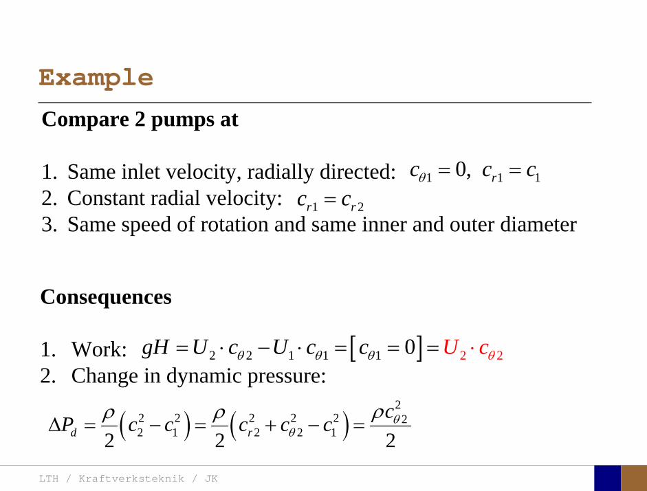
Example
1 2r rc c=
[ ] 22 2 1 1 1 20 UgH U c U c ccθ θ θ θ= ⋅ − ⋅ ⋅= = =
Compare 2 pumps at
1. Same inlet velocity, radially directed:2. Constant radial velocity: 3. Same speed of rotation and same inner and outer diameter
1 1 10, rc c cθ = =
Consequences
1. Work:2. Change in dynamic pressure:
( ) ( )2
2 2 2 2 2 22 1 2 2 12 2 2d r
cP c c c c c θθ
ρρ ρΔ = − = + − =
LTH / Kraftverksteknik / JK
Example
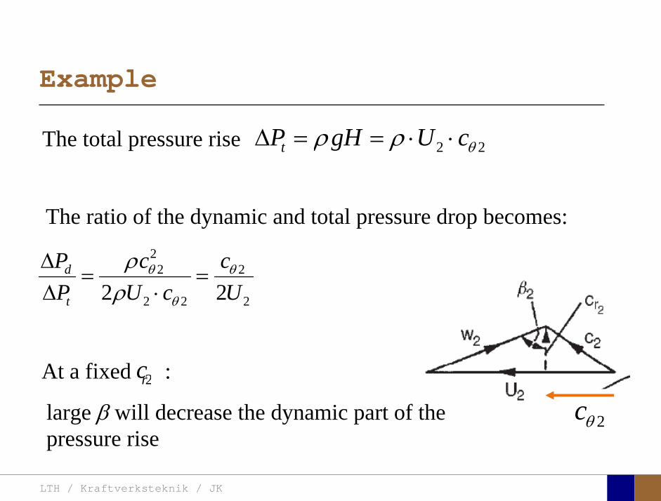
2 2tP gH U cθρ ρΔ = = ⋅ ⋅The total pressure rise
22 2
2 2 22 2d
t
P c cP U c U
θ θ
θ
ρρ
Δ= =
Δ ⋅
The ratio of the dynamic and total pressure drop becomes:
2cθ2rcAt a fixed :
large β will decrease the dynamic part of the pressure rise
LTH / Kraftverksteknik / JK
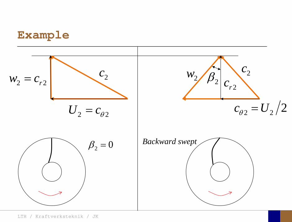
Example
2 2U cθ=
2c2rc
2 2 2c Uθ =
2c2w
2 2rw c= 2β
Backward swept2 0β =
LTH / Kraftverksteknik / JK
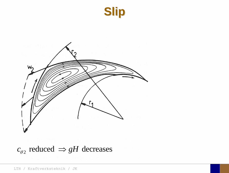
SlipSlip
2 reduced decreasesc gHθ ⇒
LTH / Kraftverksteknik / JK
Centrifugal Pumps, Fans and Compressors
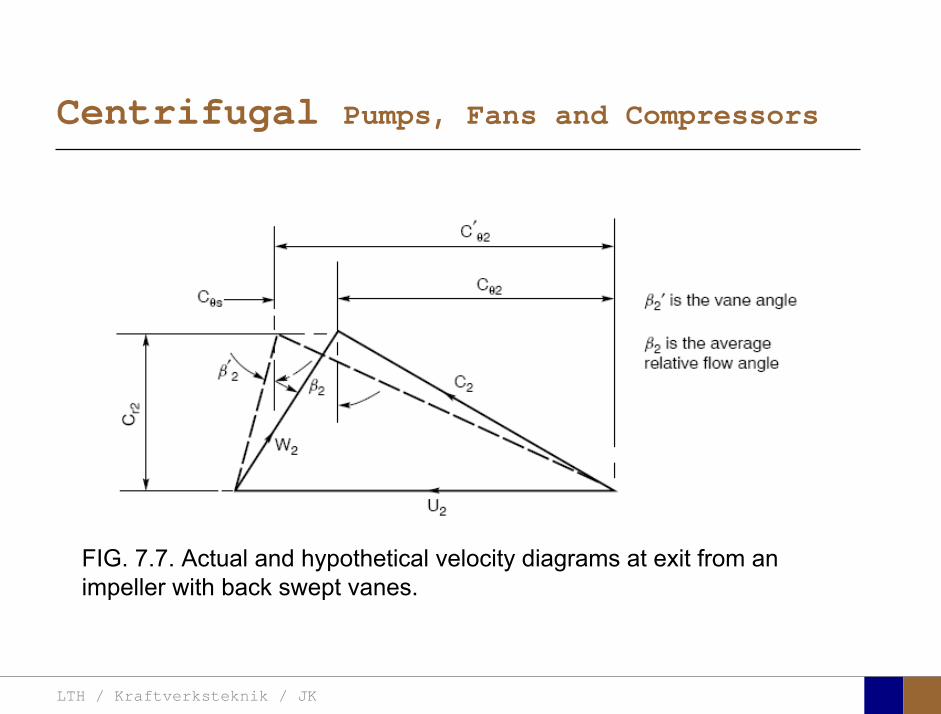
FIG. 7.7. Actual and hypothetical velocity diagrams at exit from an impeller with back swept vanes.
LTH / Kraftverksteknik / JK
Centrifugal Pumps, Fans and Compressors
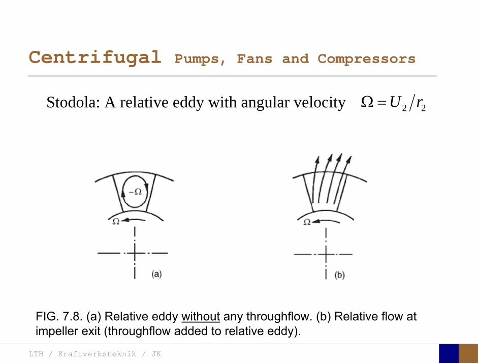
FIG. 7.8. (a) Relative eddy without any throughflow. (b) Relative flow at impeller exit (throughflow added to relative eddy).
Stodola: A relative eddy with angular velocity 2 2U rΩ =
LTH / Kraftverksteknik / JK
Centrifugal Pumps, Fans and Compressors
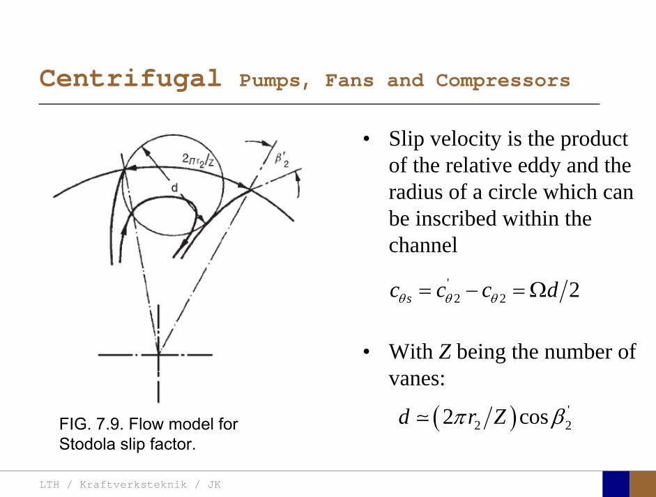
FIG. 7.9. Flow model for Stodola slip factor.
• Slip velocity is the product of the relative eddy and the radius of a circle which can be inscribed within the channel
• With Z being the number of vanes:
'2 2 2sc c c dθ θ θ= − = Ω
( ) '2 22 cosd r Zπ β
LTH / Kraftverksteknik / JK
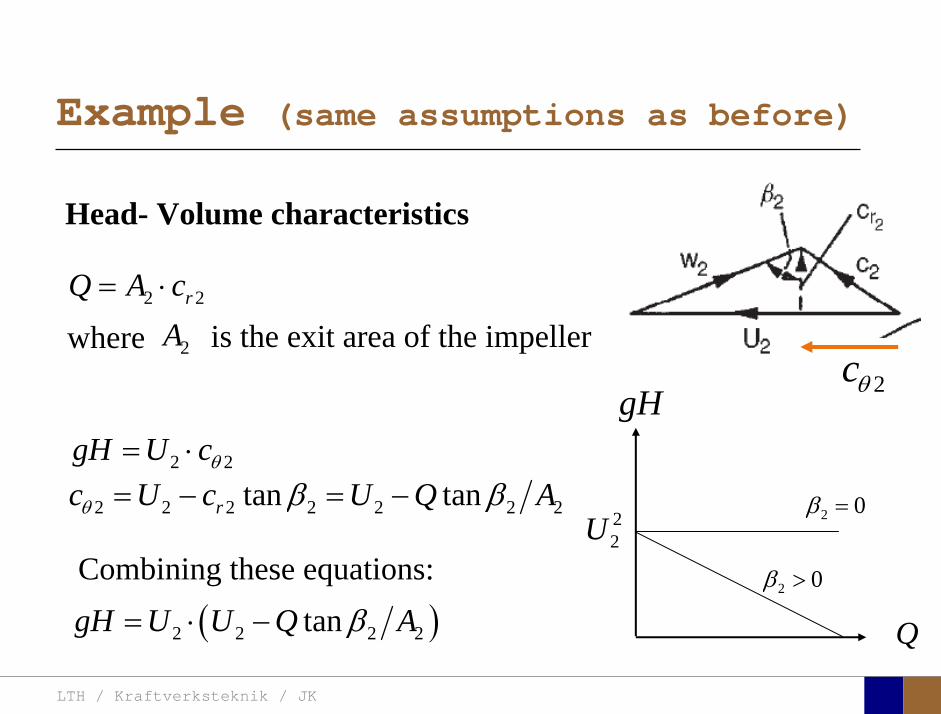
Example (same assumptions as before)
2 2rQ A c= ⋅
Head- Volume characteristics
where 2A is the exit area of the impeller 2cθ
2 2 2 2 2 2 2tan tanrc U c U Q Aθ β β= − = −2 2gH U cθ= ⋅
Combining these equations:
( )2 2 2 2tangH U U Q Aβ= ⋅ − Q
gH
22U
2 0β >
2 0β =
LTH / Kraftverksteknik / JK
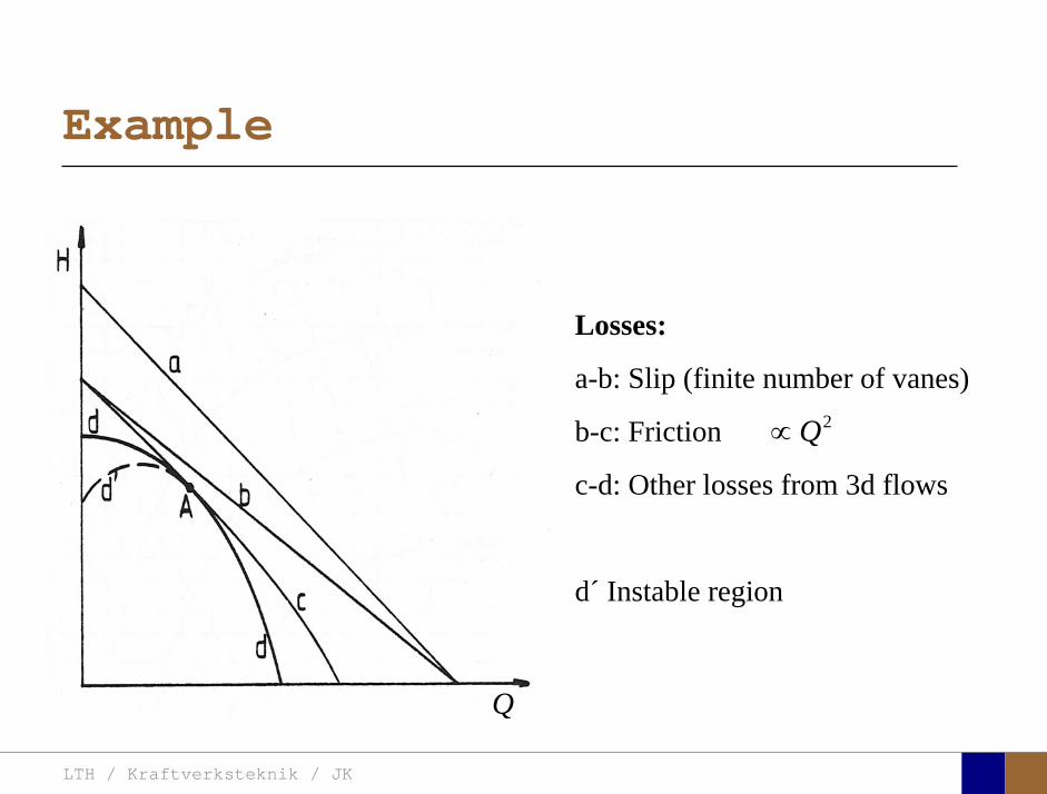
Example
Losses:
a-b: Slip (finite number of vanes)
b-c: Friction
c-d: Other losses from 3d flows
d´ Instable region
2Q∝
Q

LTH / Kraftverksteknik / JK
Operating point
LTH / Kraftverksteknik / JK
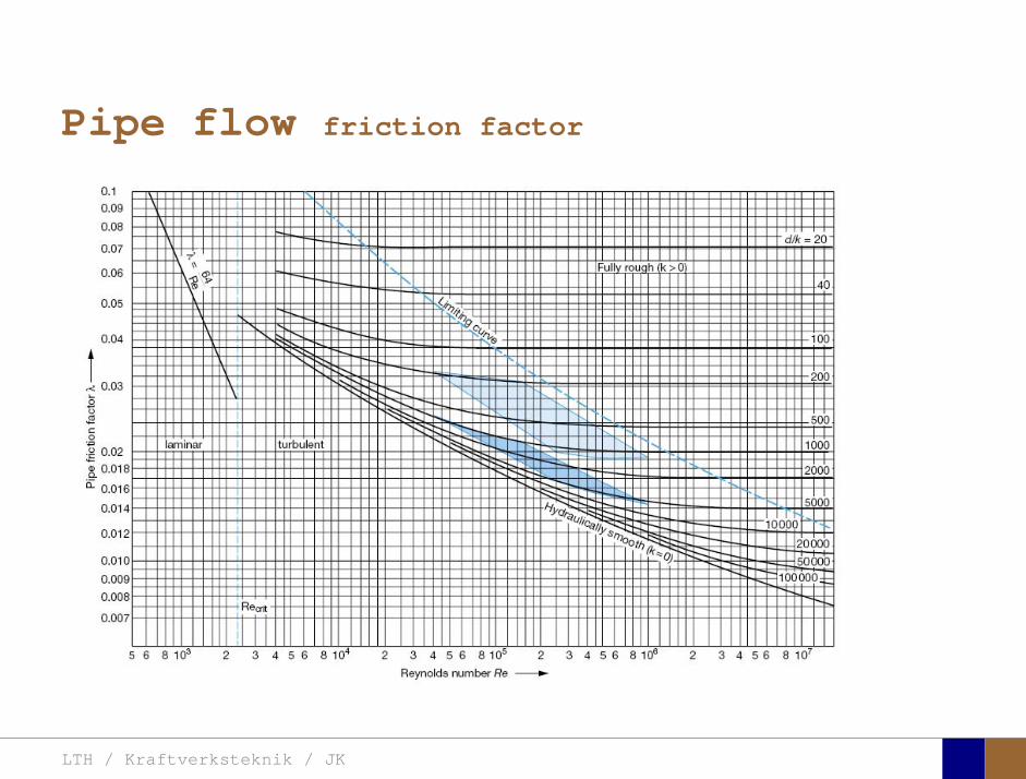
Pipe flow friction factor
LTH / Kraftverksteknik / JK
Pipe flow friction factor


![U.S. v. Dixon, 509 U.S. 688 (1993) - Columbus School of Lawclinics.law.edu/res/docs/US-v-Dixon.pdfU.S. v. Dixon, 509 U.S. 688 (1993) Dixon, Dixon. and [1] Dixon. *698. order. Dixon.](https://static.fdocuments.in/doc/165x107/5ac1e6007f8b9ad73f8d6ea8/us-v-dixon-509-us-688-1993-columbus-school-of-v-dixon-509-us-688.jpg)