Theory of the Fabry-Perot interferometer with nonparallel reflectors
4
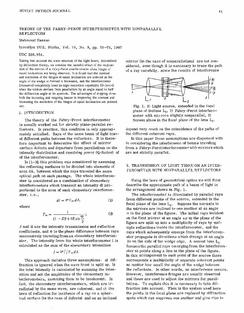
SOVIET PHYSICS JOURNAL 41 THEORY OF THE FABRY-PEROT INTERFEROMETER WITH NONPARALLEL RE FLECTORS Mahmoud Hassan Izvestiya VUZ. Fizika, Vol. 10, No. 9, pp. 73-79, 1967 UDC 535. 854. Taking into account the wave structure of the light beam, determined by diffraction theory, we consider the harmful effect of the inclina- tion of the mirrors of a Fabry-Perot interferometer when fringes of equat inclination are being observed. It is found that the contrast and resolution of the fringes of equal inclination are reduced as the angle of the wedge so formed is increased, and the intefferometer (resonator) completely loses its high-resolution capability (Q-factor) when the mirrors deviate from parallelism by an angle equal to half the diffraction angle at its aperture. The advantages of stopping down both the incoming and outgoing beams in improving the contrast and increasing the resolution of the fringes of equal inclination are pointed OUt. I. INTRODUCTION The theory of the Fabry-Perot interferometer is usually worked out for strictly plane-parallel re- flectors. In practice, this condition is only approxi- mately satisfied. Rays of the same beam of light trav- el different paths between the reflectors. It is there- fore important to determine the effect of mirror surface defects and departure from parallelism on the intensity distribution and resolving power (Q-factor) of of the interferometer. In [1-3] this problem was considered by assuming the reflecting surfaces to be divided into elements of area dA, between which the rays traveled the same optical path on each passage. The whole interferom- eter is considered as a combination of elementary interferometers which transmit an intensity dI pro- portional to the area of each elementary interferom- eter, i. e., dl = 0" 7',~,dA, (1) where 1 . (2) Too= (1) ' (1 -- R)2+4R sin -- 2 ~ and R are the intensity transmission and reflection coefficients, and @ is the phase difference between rays successively traveling from an elementary interferom- eter. The intensity from, the whole interferometer I is calculated as the sum of the elementary intensities l=o~fj'T~odA. This approach includes three assumptions: a) dif- fraction is ignored when the wave front is split up, b) the total intensity is calculated by summing the inten- sities and not the amplitudes of the elementary in- terferometers, assuming them to be incoherent. In fact, the elementary interferometers, which are ir- radiated by the same wave, are coherent, and c) the laws of reflection for incidence of a ray on a spher- ical surface (in the case of defects) and on an inclined mirror (in the case of nonparallelism) are not con- sidered, even though it is necessary to trace the path of a ray carefully, since the results of interference L, --T Fig. 1. 1) Light source, extended in the focal plane of thelens L 1, 2) Fabry-Perot interfero- meter with mirrors slightly nonparallel, 3) Screen place in the focal plane of the lens L 2. depend very much on the coincidence of the paths of the different coherent rays. In this paper these assumptions are dispensed with in considering the interference of beams traveling from a Fabry-Perotinterferometer with mirrors which are not strictly parallel. 2. TRANSMISSION OF LIGHT THROUGH AN INTER- FEROMETER WITH NONPARALLEL REFLECTORS Using the laws of geometrical optics we will first describe the approximate path of a beam of light in the arrangement shown in Fig. i. The interferometer is illuminated by parallel rays from different points of the source, extended in the focal plane of the lens L I. Suppose the normals to the mirrors are inclined to one another at an angle in the plane of the figure. The initial rays incident on the first mirror at an angle +~ in the plane of the figure are split up into a multiplicity of rays by mul- tiple reflections inside the interferometer, and the rays which subsequently emerge from the interferom- eter propagate in directions which diverge at an angle 2~ on the side of the wedge edge. A second lens L 2 focuses the parallel rays emerging from the interferom- eter at points along a line in the plane of the figure. In this arrangement to each point of the source there corresponds a multiplicity of separate coherent points no matter how small the angle of the wedge between the reflectors. In other words, no interference occurs. However, interference fringes are usually observed and these are used to adjust the mirrors for paral- lelism. To explain this it is necessary to take dif- fraction into account. Then in the system used here the points in the focal plane are replaced by diffraction spots which can suppress one another and give rise to
-
Upload
mahmoud-hassan -
Category
Documents
-
view
216 -
download
0
Transcript of Theory of the Fabry-Perot interferometer with nonparallel reflectors
SOVIET PHYSICS JOURNAL 41
THEORY OF THE FABRY-PEROT INTERFEROMETER WITH NONPARALLEL RE FLECTORS
Mahmoud Hassan
I zves t i ya VUZ. F iz ika , Vol. 10, No. 9, pp. 73-79 , 1967
UDC 535. 854.
Taking into account the wave structure of the light beam, determined by diffraction theory, we consider the harmful effect of the inclina- tion of the mirrors of a Fabry-Perot interferometer when fringes of equat inclination are being observed. It is found that the contrast and resolution of the fringes of equal inclination are reduced as the angle of the wedge so formed is increased, and the intefferometer (resonator) completely loses its high-resolution capability (Q-factor) when the mirrors deviate from parallelism by an angle equal to half the diffraction angle at its aperture. The advantages of stopping down both the incoming and outgoing beams in improving the contrast and increasing the resolution of the fringes of equal inclination are pointed OUt.
I. INTRODUCTION
The theory of the Fabry-Perot interferometer is usually worked out for strictly plane-parallel re-
flectors. In practice, this condition is only approxi- mately satisfied. Rays of the same beam of light trav- el different paths between the reflectors. It is there- fore important to determine the effect of mirror surface defects and departure from parallelism on the
intensity distribution and resolving power (Q-factor) of
of the interferometer. In [1-3] this problem was considered by assuming
the reflecting surfaces to be divided into elements of area dA, between which the rays traveled the same optical path on each passage. The whole interferom-
eter is considered as a combination of elementary i n t e r f e r o m e t e r s which t r a n s m i t an in tens i ty dI p r o - por t iona l to the a r e a of each e l e m e n t a r y i n t e r f e r o m -
e t e r , i . e . ,
dl = 0" 7',~, dA, (1)
where
1 . ( 2 ) Too= (1) '
( 1 - - R)2+4R sin - - 2
~ and R a r e the in tens i ty t r a n s m i s s i o n and r e f l e c t i o n
coe f f i c i en t s , and @ is the phase d i f f e r ence be tween r a y s s u c c e s s i v e l y t r a v e l i n g f r o m an e l e m e n t a r y i n t e r f e r o m - e t e r . The in tens i ty from, the whole i n t e r f e r o m e t e r I is ca l cu la t ed as the sum of the e l e m e n t a r y i n t ens i t i e s
l=o~f j 'T~odA.
This approach inc ludes t h r e e a s sumpt ions : a) d i f - f r ac t i on i s ignored when the wave f ront is spl i t up, b)
the to ta l in tens i ty is ca l cu la t ed by summing the in ten- s i t i e s and not the ampl i tudes of the e l e m e n t a r y in-
t e r f e r o m e t e r s , a s s u m i n g them to be i ncohe ren t . In
fact , the e l e m e n t a r y i n t e r f e r o m e t e r s , which a r e i r -
r ad i a t ed by the s a m e wave, a r e cohe ren t , and c) the
laws of r e f l e c t i o n for inc idence of a r ay on a s p h e r - ica l s u r f a c e (in the c a s e of defects) and on an inc l ined
mirror (in the case of nonparallelism) are not con- sidered, even though it is necessary to trace the path of a ray carefully, since the results of interference
L, - - T Fig. 1. 1) Light sou rce , extended in the focal p lane of the lens L 1, 2) F a b r y - P e r o t i n t e r f e r o - m e t e r with m i r r o r s s l ight ly nonpara l l e l , 3) S c r e e n p lace in the focal plane of the lens L 2.
depend v e r y much on the co inc idence of the paths of the d i f fe ren t c o h e r e n t r a y s .
In th is paper t he se a s sumpt ions a r e d i spensed with in c o n s i d e r i n g the i n t e r f e r e n c e of b e a m s t r a v e l i n g f r o m a F a b r y - P e r o t i n t e r f e r o m e t e r with m i r r o r s which
are not strictly parallel.
2. TRANSMISSION OF LIGHT THROUGH AN INTER- FEROMETER WITH NONPARALLEL REFLECTORS
Using the laws of geometrical optics we will first describe the approximate path of a beam of light in
the arrangement shown in Fig. i.
The interferometer is illuminated by parallel rays from different points of the source, extended in the
focal plane of the lens L I. Suppose the normals to the mirrors are inclined to one another at an angle
in the plane of the figure. The initial rays incident
on the first mirror at an angle +~ in the plane of the figure are split up into a multiplicity of rays by mul-
tiple reflections inside the interferometer, and the rays which subsequently emerge from the interferom-
eter propagate in directions which diverge at an angle 2~ on the side of the wedge edge. A second lens L 2
focuses the parallel rays emerging from the interferom- eter at points along a line in the plane of the figure. In this arrangement to each point of the source there
corresponds a multiplicity of separate coherent points no matter how small the angle of the wedge between the reflectors. In other words, no interference occurs.
However, interference fringes are usually observed
and these are used to adjust the mirrors for paral-
lelism. To explain this it is necessary to take dif-
fraction into account. Then in the system used here the points in the focal plane are replaced by diffraction
spots which can suppress one another and give rise to

42 IZVESTIYA VUZ. FIZIKA
i n t e r f e r e n c e . M o r e o v e r , even though the spo t s a r e a r r a n g e d d i s con t inuous ly , i n t e r f e r e n c e o c c u r s when the l ight p r o p a g a t e s in t he r e g i o n behind the foca l p l ane .
y
b # j J
~ ........--..~t
,h Y
Fig . 2. Pa th of the r a y s when l ight p a s s e s th rough the i n t e r -
f e r o m e t e r .
A b e r r a t i o n s of the l ens L 2 i n c r e a s e the s u p e r p o s i t i o n of the d i f f r ac t ion spo t s in i t s foca l p l ane .
Below we c o n s i d e r the i n t e r f e r e n c e of the b e a m s e m e r g i n g f r o m an i n t e r f e r o m e t e r wi th n o n p a r a l l e l r e - f l e c t o r s us ing the H u y g e n s - F r e s n e l p r i n c i p l e .
3. I N T E R F E R E N C E OF BEAMS OF LIGHT P R O P A - GATING IN DIVERGING DIRECTIONS
F o r a d e t a i l e d d e t e r m i n a t i o n of the path of r a y s p a s s i n g th rough the i n t e r f e r o m e t e r we can choose a s y s t e m of c o o r d i n a t e s a s shown in F ig . 2, so tha t the p r i n c i p a l p lane of the l ens L t l i e s in the yz p lane and the n o r m a l to i t a t the o r ig in of c o o r d i n a t e s O is the a b s c i s s a ax i s x, which p a s s e s th rough one of the ang les of the f i r s t m i r r o r , which co inc ide s wi th the x -X p lane and cu t s off an i n t e r c e p t of b in the y d i r e c t i o n and a in the z - d i r e c t i o n . Let the normals '~to both m i r r o r s conta in an ang le a be tween t hem in the xy p lane , ff the r e a r m i r r o r cu t s the x ax i s a t the poin t x = X + h, the equat ion of t h i s m i r r o r in the xy p lane wi l l be
x - - X Q - h + ytg~ (3)
A p a r a l l e l b e a m inc iden t on the i n t e r f e r o m e t e r at an angle gowith the x - a x i s i s sp l i t into a m u l t i p l i c i t y of p a r a l l e l b e a m s which s u c c e s s i v e l y p r o p a g a t e in s ide the i n t e r f e r o m e t e r mak ing ang les
n - - | ~ @ 2 ( ] - - 1)a], r -,;- 2 (1- - 1)~
with the x axis in the s a m e xy p l ane (i is the n u m b e r of the beam e m e r g i n g f r o m the i n t e r f e r o m e t e r ) . H e r e d i f f r ac t i on ins ide the i n t e r f e r o m e t e r is i gno red fo r m i r r o r - t o - m i r r o r r e f l e c t i o n when the r a t i o of the r e - f l ec t ing a r e a s to the m i r r o r spac ing is l a r g e (each m i r r o r conta ins a l a r g e n u m b e r of F r e s n e l zones ff one r e g a r d s each one f r o m t h e c e n t e r of the o ther ) .
A c c o r d i n g to the H u y g e n s - F r e s n e l p r i n c i p l e each wave f r o n t can be d iv ided into in f in i t e ly s m a l l p a r t s . The n o r m a l to each p a r t i s c a l l ed a r a y . F r o m the s u r f a c e of each e l e m e n t a r y p a r t e l e m e n t a r y w a v e s
d s j - - c . 0 R i-1 e ~r �9 ap ~ (4)
p r o p a g a t e with a m p l i t u d e s p r o p o r t i o n a l to the a r e a (ad~) of the e l e m e n t a r y s u r f a c e at the r e a r m i r r o r
r and with phase @j, depending on the opt icaI path which
each r a y t r a v e l s ins ide the i n t e r f e r o m e t e r ( c r o s s - ha tched in Fig. 2)
@j (b o-to 2cose x
y--L ]
• xncos + I) 1-2x] cos • n = l n = 2
j - i
• ~ Yn x n = l
x cos [~ + ( 2 n - - 1)a] + x j ( c o s ~ j - - cosg) +
+ y j ( s i n ~ j - - s i n g ) + x c o s , ~ + y s i n g } , (5)
w h e r e (Xn, Yn) a r e the po in t s w h e r e the r a y s t r i k e s the r e a r m i r r o r , n = (27r/X) i s the wave n u m b e r , X is the wavelength , ~oj = qo + 2(j - 1)~, ~ = (yj - yi) s ec a , and if0 i s the phase of the l ight wave en te r ing the i n t e r - f e r o m e t e r at the o r ig in of c o o r d i n a t e s at the ins tan t when the j - t h e l e m e n t a r y wave r e a c h e s the po in t (x , y). The e l e m e n t a r y waves of one b e a m p ropaga t ing in space in any d i r e c t i o n ~b i n t e r f e r e and l e ad to a to ta l w a v e
sin ~ ( b - - y j ) B sj = ca ~ RJ -~ ~ e~J, (6)
- - B k
w h e r e B = sin (~i + ~) - - sin (~] + ~), (7)
/2h s!n ~ i - - s i n q~ ~ J = ~ ~ [ 2 tg~ + 2 X x
2 s i n ( ] - - l ) a s i n ~ + ] - - ~ sin ~- + •
s i n s
i i
+ xj (cos q~j - - ~) + yj (sin ~j - - sin qb) +
+ 12 (b -- y)) B + x cos + y sin 9} , (8)
! . (xj, y j ) i s the point a t which the e x t r e m e (lowest) r a y of the j - th beam i n t e r s e c t s the r e a r m i r r o r , and (b - yj) i s the width of the j - t h b e a m leav ing the i n t e r f e r o m e t e r . A c c o r d i n g to (6) the t h e o r y of d i f f rac t ion , d e t e r m i n i n g the wave s t r u c t u r e of the l ight b e a m , s u b s t i t u t e s fo r i t a m u l t i p l i c i t y of waves which can p r o p a g a t e in s p a c e with a m p l i t u d e s which a r e r e d u c e d in p r o p o r t i o n to the d i v e r g e n c e (fi = ~ = ~j) f r o m the d i r e c t i o n of g e o - m e t r i c a l p ropaga t i on ( F i g . 3) in which the wave with m a x i m u m a m p l i t u d e i s p r o p a g a t e d . The m o s t p o w e r - ful f lux of l ight i s con ta ined i n s ide an ang le
2X 2~m~. = ( b - - y ) ) c o s [,? +(27-- 1)~,1
4. FRINGES OF EQUAL INCLINATION OF THE WEDGE I N F E R O M E T E R
F r i n g e s of equal inc l ina t ion , l o c a l i z e d at inf ini ty , a r e f o r m e d by the i nc ohe re n t s u c c e s s i o n of l ight waves ,
SOVIET PHYSICS JOURNAL 43
which a r i s e due to m u l t i p l e r e f l e c t i o n s i n s ide the i n t e r - f e r o m e t e r . Due to d i f f r ac t i on when e m e r g i n g f r o m the i n t e r f e r o m e t e r i ncohe ren t ne ighbor ing points of the l ight sou rce t r a n s m i t l ight waves in the s a m e d i r e c - Uon ~ giving an i n t ens i t y d e t e r m i n e d by
I = S S ss* do ~ , (9)
w h e r e
s i n 2 1 ~caO SS* = ~ c 2 - 2
\ 2 X
[,2 X R j - ~ e - i ( j - ~ m X 1 ~ ( ~ - - ~ j ) x
. . . . . . . . . ( l O ) • j~,i Rj-~e'<j-~'~ .j~:(~_+~) It i s a s s u m e d tha t the po in t s of the l ight s o u r c e
which e s s e n t i a l l y con t r i bu t e to the l ight waves in a s ing le d i r e c t i o n a r e a r r a n g e d ove r a s m a l l e l e m e n t of the s u r f a c e of the s o u r c e in view of the s m a l l n e s s of the ang le of d i f f r ac t i on at t h e a p e r t u r e of the i n t e r - f e r o m e t e r . Hence in (9) and (10) the ang l e s of i n - c idence of the l ight on the i n t e r f e r o m e t e r f r o m t h e s e po in ts a r e a s s u m e d to be the s a m e ( n o r m a l i nc idence
in our ease ) . Consequent ly , we t a k e �9 = 2uh in (10). Thus the in tens i ty c a l c u l a t e d by i n t e g r a t i n g a l l the p r o d u c t s of t e r m s of the f i r s t sum by the t e r m s of the second sum in (10) s e p a r a t e l y wi l l be
_ _ [ R sin(2,~q + q)) , A ~ . c ~ X~ / 1 1 arctg . . . . . . ~- I - - 1 - - ~ I. @ 2~q _ l - - R c o s ( 2 " ~ q + @ )
+ arctg 1 ~ c~- s (~ - - -@)JJ ' (11)
where
q = L-~-.
The i n t e r f e r e n c e p a t t e r n d e s c r i b e d by (11) h a s the fo l - lowing c h a r a c t e r i s t i c s:
1) When the angle of the wedge c~ tends to ze ro , Eq. (11) b e c o m e s the we l l -known A i r y funct ion .
F ig . 3. D i f f r ac t ion of l ight when the j - t h b e a m e m e r g e s
f rom the i n t e r f e r o m e t e r .
2) When we subs t i tu te c~ = X / 2 b in (11) the i n t ens i ty b e c o m e s
z = A (~ cx) ~ (12) 1 - - R z
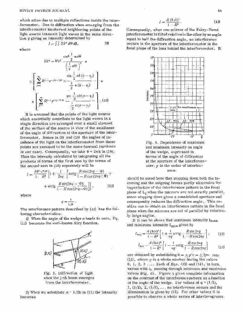
Consequen t ly , when one m i r r o r of the F a b r y - P e r o t l i n t e r f e r o m e t e r i s t i l t e d r e l a t i v e to the o the r b y a n angle equal to half the d i f f r ac t ion ang le , no i n t e r f e r e n c e o c c u r s in the a p e r t u r e of the i n t e r f e r o m e t e r in the foca l p lane of the l ens behind the i n t e r f e r o m e t e r . It
0z
Fig . 4. Dependence of m a x i m u m and m i n i m u m i n t e n s i t y on angle of the wedge , e x p r e s s e d in t e r m s of the angle of d i f f r ac t ion at the a p e r t u r e of the i n t e r f e r o m - e t e r ; p is the o r d e r of i n t e r f e r -
ence .
should be noted here that stopping down both the in- coming and the outgoing beams partly eliminates the imperfection of the interference pattern in the focal
plane of L 2 when the mirrors are not strictly parallel, since stopping down gives a constricted aperture and
consequently reduces the diffraction angle. This en-
ables one to obtain an interference pattern in the focal plane when the mirrors are out of parallel by relative-
ly large angles. 3) It can be shown that maximum intensity Imax
and minimum intensity Imi n given by
t A(~cX)2[ Rs in2~q ] ~a.~ ----- ~ R2 1 + 1 arctg , (13)
~q 1 - - R cos 2~q
Imi, A(0&) 2 [ 1 _ 1 arctg Rsin2~q i = 1 - - R 2 ~q 1 - - - - R c o ~ q j (14)
a r e ob ta ined by subs t i tu t ing@ = ,-L_p'~ = ~__ 2p~, into (11), whe re p i s a whole n u m b e r having the va lues 0, 1, 2, 3 . . . . Each of Eqs . (13) and (14), in tu rn , v a r i e s with q, p a s s i n g th rough m i n i m u m and m a x i m u m va lues (Fig. 4 ) . F i g u r e 4 g ives c o m p l e t e i n fo rma t ion on the c o n t r a s t of the i n t e r f e r e n c e p a t t e r n a s afunet iOn of the angle of the wedge. F o r va lues of q = (1/2) , 1, (3/2) , 2, (5/2) , . . . no i n t e r f e r e n c e o c c u r s and the i l l umina t i on is given by (12). F o r o ther va lue s it is p o s s i b l e to o b s e r v e a whole s e r i e s of i n t e r f e r o g r a m s .

44 IZVESTIYA VUZ. FIZIKA
The f irs t in terferogram is observed when the angle of the Wedge varies in the limits 0 _< ~ < (X/2b), and its contrast decreases considerably as x is increased. The contrast of the second interferogram is manv t imes less than the contrast of the f i rs t (Fig. 4), and its maxima OCcur at those places where the previous minima occurred ear l ier , and the minima take the place of the maxima of the f i rs t pattern. Further in- c rease in ~ leads to a sequence of other in terfero- grams which replace each other but with decreasing contrast.
4) The limit of resolution (the width of the reso- nance curve) and the resolving power (Q-factor) of the Fab ry :Pe ro t interferometer (resonator) with mi r ro r s which are not str ict ly parallel can be Calcu- lated by presenting expression (11) graPhically and determining from the shape of the fringes obtained their width and Corresponding resolving power. The resolving power of the in terferometer is zero when its m i r r o r s deviate from paral lel ism by an angle equal to half the diffraction angle at the outgoing ap- er ture. This result is stated qualitatively in [4] but cannot be derived from the calculations. Basov and his co-workers [5 ] calculated the Q of a resonator with nonparallel mi r ro r s by assuming that a ray is inside the resonator for a finite time before it leaves as a result of "walk-off." They neglect the divergence and vignetting of the emerging beams which cause serious losses.
5. CONCLUSIONS
1) Taking into account diffraction at the aperture of the wedge interferometer expressions have been
obtained for the intensity distribution of fringes of equal inclination in the interference pattern.
2) It has been found that the resolving power (Q- factor) of the interferometer decreases with increas- ing angle of inclination of the mi r ro r s , and is zero when the angle of the wedge is equal to half the angular width of the principal diffraction maxima at the inter- ferometer aperture.
3) The usefulness of stopping down the incoming and outgoing light beams has been shown.
The author thanks Professor F. A. Korolev for his interest .
RE FERENC ES
i. Ch. Dufour and R. Picca, Rev. d'Opt., 24, no.
I, 19, 1945. 2. I. R. Chabbal, J. Rech. Cent. Nat. Reeh. Sc.,
no. 24, 138, 1953. 3. R. Chabbal, J. Phys. etRad., vol. 19, no. 3,
295, 1958. 4. J. Koeik, M. C. Newstein, J. Appl. Physc.,
32, no. 2, 178, 1961. 5. N. G. Basov, O. N. Krokhin, and Yu. M. Popov,
Uspekh. fiz. Nauk, 72, 2, 161, 1960.
1 June 1966 Revised 27 March 1967
Moscow State University