THEORY OF PERFORMANCE OF ISOTHERMAL SOLID-NOSE … · THEORY OF PERFORMANCE OF ISOTHERMAL...
10
THEORY OF PERFORMANCE OF ISOTHERMAL SOLID-NOSE HOTPOINTS BORING IN TEMPERATE ICE* By R . L. SHREVE ( Department of Geology and Institute of Geophysics, University of California, Los Angeles, Calif.) ABST RACT. T he perf ormance of a th ermal ice-drill h av ing a sm oo th , so li d, impervious frontal surface, termed a "solid-nose hot point " , is d e te rmin ed by th e ve lociti es, pressur es, a nd tempe ratur es in the thin layer of warm m elt wat er betwec n th e hotpoint an d the ice. Th e effi ciency, th e speed of pene tr a ti on, the temperat ure of the fronta l surface , and the distr ibut ion of press ure on it can be calc ul ated from the eq uations of non -turbul e nt fluid fl ow. Fo r h otpoints whose fronta l surf aces are iso th e rmal and axially symmetric, these quant i ti es ar e func ti ons of th e to ta l in put of power Q, of th e weig ht W on th e hotpoint, of the ra diu s a and "s hape fac tor" S of the fro nt al su rface, and of th e pe rtine nt physical pro perties of wa ter and ice. The cal- culation shows t ha t with incr easing "pe rf orman ce nu mbe r" N = A QS/a WI th e e ffi ciency E d ecreases and th e surface temp er atu re 0 0 increases. Th us, for examp le, E = I' 00 an d 0 0 = OC C. when N = o· 0; E = o' 76 a nd 00 = 48° C. when N = I' 4; and E = 0·60 and 00 = 103 ° C. when N .= 3' o. T he coeffi c ie nt .iI is a constant e qual to 3'4 kg wt . l cm. kW. - '. Th e shape factor S is a dimensio nl ess nu mber between 0 a nd I th at var ies according to th e sh ape of th e fro nt al su rf ace, great er va lu es of S being associated with blunter profiles (thus S = I' 0 for a plane frontal sur face perpendicular to the axis). For co ring ho tpo ints th e sa me n umerical results are o bt ained, bu t the pe rf or man ce numbe r is given by N = .iI QS I (I - 'tITj' ) + (I + 'tIT i') In 'tIT j)l/a( W( I - 'tIT i') ) In 'l7T j ]l , where 2'tITia is th e inside dia meter of th e hotpo int. R EsUMI\. Le rendement d'une sonde a glace th e rm ique ayant une sur fa ce fr ont a le lisse, so lide et etanche, appel ee "so li d-nose hotpoint" , est det er mine par les vitesses, les press ions et les temperatur es de la min ce cou che d' eau de fonte se trouva nt entre la point e chaude et la glace. Le rende ment , la vitesse de p en e tra ti on, la te mp era tur e et la rt' part ition de la press io n sur la su rf ac e fronta le peuv e nt etre calcules a I' aid e des eq uati ons d'ecou !ement d' un fl uide n on turbul ent. Po ur d es po intes chaudes a sur fac e frontale iso th erme de symetrie ax iale, ces q uant it es sont f onct ions de I'appo rt total de chale ur Q, du poids W agissan t sur la point e cha ude, du ra yon a et du " coefficien t d e profil" S de la su rf ace fro nt ale, ainsi que des proprietes phys iques de I' ea u et de la g lace. Le calcul mont re qu' avec I'augmen ta ti on du "coc ffic ie nt de re nd ement " N = A QS/a WI le rende ment E d ecroit et la temp era tur e de surf ace 8 0 croit. Ainsi pa r e xcmp le E = 1,00 et 0 0 = 0° C po ur N = 0,0; E = 0,76 et 0 0 = 48° C pou r N = 1>4 ; et E = 0,60 et 0 0 = 103 °C si N = 3,0. Le coe ffi c ient ,1 est un e const an te ega le a 3,4 kgpl / cm kW - '. Le coe ffic ie nt de profi l S est un no mbr e sans dimension compr is en tr e 0 et I, qui varie en fonction du profil de la surf ace fronta le, les fo rt es va leu rs de S etan t assoeiees a des pro fil s plus obtus (ain si S = 1,0 pour un e surf ace fr ontale plane perpe ndi culaire a I'axe ). Pou r des car o tt eur s a pointe cha ucl e les memcs resultats nu mer iq ues s ont ob te nu s, ma is le coeffi cient de rend ement est donne par N = AQS [( I - 'tIT i' ) + (I + 'tIT i') In 'tIT jJl/ar W( I - 'tIT j ')) In 'tIT j] 1 ou 2'tIT ja est le diametre int crie ur d e la po inte chaud c. Z USAMMEN f ASSUNG. Die Leistun g eines thermi schen Eisbohrers mit gla tt er, star rer un ci un dur c hl assiger Spit ze ("solid-nose hot point ") ist best immt cl lIrch d ie Geschwindigkeiten, Drucke u nci Tem pe r at ur en in der dun nen Sc hi c ht wa rmcn Sch me lz wasser ' zwischcn Ei s un d Bohrer. Mi t hi lf e der Gleichungen fur laminarcs F li essen ka nn ma n di e wirksa me Leistllng, die Vortri ebsgeschwincligkcit, die Te mpe rat ur der Sp itze und cli e Dr llc kve rt e ilun g libe r die Spi tze no ber Aa chc wa hr e nd d es Bo hrhetriebes be r cc hn en. Diese Werte sincl an rotati onssymme trischen B ohre rn mit isotherma ler Spitze noberfl ac he Fu nkt ion en de r zugefuhrtcn Warme Q .. d es an d er Bohrerspitze wirksa men Gewic ht sa nt eils W, des R adi us a, des Fo rm- Koeffiz ien ten S fur das Sp itzen- profi l u nd de l" in Betr ac ht komme nd en ph ys ikalisc he n Eigenschaften von Wasser u nd Eis. Bei zu nehmend er " Leistungs zahl " N = A QS/a W I n imm t de r Wirkun gsgrad E ab. un d di e S pit zen te mp eratur 0 0 zu. So wircl zu m Beisp iel E = 1,00 und 0 0 = 0° C, wenn .N = 0,0; E = 0,76 und 80 = 48°, we nn JV = J >4: oder E = 0,60 und 80 = 103 °, we nn N = 3,0. Die Zahl .1 ist eine Kons tante mit dcm Wert 3>4, we nn wir al s Dimensio nen kgl cm kw - ' setzen (kg als Gewi chtse inh eit). Der Form-Koe ffi zient S ist ein e dimensio nsl osc Zahl zwisch en 0 und I. di e si eh mit der For m cler Bohrerspitze a nd e rt : je stumpfer das Profil ist, umso hoher der Wert von S (also S = 1,0 fur den rechtwinklig ende nd en zy lind er). Fur Ke rnb o hl"{' r gilt N = AQS[( I - 'tIT;,) + (I + 'tIT;'l In 'tITi]l/a[ W( I - 'tIT;' )) In 'tIT j] 1 mit denselben \ "' erten wie zuvor und mil 2'tIT ja al s Inn e ndurchmesser d es K e rnr ohrs. INTRODUCTION The performance of any type of thermal boring device, or " hotpoint", that is drilling through clean, solid, temperate ice is entirely determined by the velocities, pressures, and temperatures in the warm melt water at the bottom of the hole. In the case of a hotpoint with • Contribution No. 131 of the Institute of Geophysics, University of Calif o rnia , Los Angeles, Calif ornia . 15 1
-
Upload
truongthien -
Category
Documents
-
view
227 -
download
1
Transcript of THEORY OF PERFORMANCE OF ISOTHERMAL SOLID-NOSE … · THEORY OF PERFORMANCE OF ISOTHERMAL...

THEORY OF PERFORMANCE OF ISOTHERMAL SOLID-NOSE HOTPOINTS BORING IN TEMPERATE ICE*
By R . L. SHREVE
(Department of Geology and Institute of Geophysics, University of California, Los Angeles, Calif. )
ABSTRACT. T he performance of a thermal ice-drill h aving a smooth , solid, impervious frontal surface, termed a "solid-nose hotpoint" , is d e termined by the velocities, pressures, and temperatures in the thin layer of warm m elt water betwecn the hotpoint and the ice. The effic iency, the speed of pen etra tion, the tempera ture of the fronta l surface, and the distribution of pressure on it can be calcula ted from the equations of non-turbulent fluid flow. For hotpoints whose fronta l surfaces a re iso therma l and axia lly symmetric, these quant ities are fu nctions of the to ta l input of power Q , of the weight W on the hotpoint , of the ra dius a and "shape fac tor " S of the frontal su rface, a nd of the p ertinent physical proper ties of wa ter and ice. The calcula tion shows that with increasing " performance number" N = A Q S/a WI the efficiency E d ecrea ses a nd the surface temperature 00 increases. Thus, for example, E = I ' 00 and 00 = OC C. when N = o· 0; E = o' 76 and 00 = 48° C. when N = I ' 4; a nd E = 0 · 60 and 00 = 103° C . when N .= 3' o. T he coeffic ient .iI is a cons tant equa l to 3'4 kg wt.l cm. kW. - ' . The shape facto r S is a d imensionl ess nu mber between 0 a nd I that varies according to the shape of the fronta l surface, greater values of S being associa ted with blun ter p rofiles (thus S = I ' 0 fo r a p lane fronta l surface perpendicula r to the ax is). For cori ng hotpoints the sam e numer ica l results a re obta ined, bu t the performance number is g iven by
N = .iI QSI ( I - 'tITj' ) + ( I + 'tIT i') In 'tIT j)l /a( W( I - 'tIT i') ) In 'l7T j]l , where 2'tITia is the ins ide diameter of the hotpoint.
R EsUMI\. Le rendement d 'une sonde a glace therm ique ayan t une surface fronta le lisse, so lide e t e tanche, appelee "solid-nose hotpoin t" , est determine par les vitesses, les press ions e t les temperatures de la mince couche d 'eau de fonte se tro uvant entre la pointe cha ud e e t la glace. Le ren d ement, la vitesse d e penetra tion, la temperature e t la rt' partition de la press ion sur la su rface frontale peuvent e tre calcules a I'aide d es equations d 'ecou!emen t d 'un fl uide non turbulen t. Pour des poin tes chaudes a surface fron tale isotherme de symetrie axiale, ces q uantites sont fonctions de I'apport to ta l d e cha leur Q, d u poids W agissan t sur la pointe chaude, du rayon a et du " coefficien t d e profi l" S de la surface frontale, a insi que d es proprietes p hysiques de I'eau et de la glace. Le calcul montre q u 'avec I'augmen ta tion du " cocffic ient d e rendement" N = A QS/a WI le rendement E decroit et la tempera ture de surface 80 c roit. Ainsi par excmple E = 1,00 e t 00 = 0° C pour N = 0,0 ; E = 0,76 e t 00 = 48° C pour N = 1>4 ; e t E = 0,60 et 00 = 103 °C si N = 3,0. Le coeffi c ient ,1 est une constan te egale a 3,4 kgpl /cm kW - ' . Le coeffic ient de profi l S est un nombre sans dimension compris entre 0 e t I , q u i varie en fonction d u profi l de la surface fronta le, les fortes valeurs de S etan t assoeiees a des profils plus ob tus (ainsi S = 1,0 pour une surface fronta le plane perpendiculaire a I'axe). Pour des carotteurs a poin te chaucle les memcs resulta ts numeriq ues sont obtenus, mais le coeffi c ient d e rendement est donne par
N = AQS [( I - 'tITi' ) + ( I + 'tIT i') In 'tIT jJl /a r W( I - 'tIT j')) In 'tIT j]1 ou 2'tIT ja est le di ametre intcr ieur d e la pointe chaudc .
ZUSAMMEN f ASSUNG. Die Leistung e ines thermischen E isbohrers mi t g la tter , starrer unci undurchlass iger Spitze (" solid-nose hotpoint") ist bes timmt cl lIrch d ie G eschwind igkeiten , D rucke unci Tem peraturen in der dunnen Schicht wa rmcn Schmelzwasser ' zwischcn Eis und Bohrer. Mi t hi lfe der Gleichungen fur lamina rcs Fliessen ka nn man die wirksame Le istllng, d ie Vortriebsgeschwincligkcit, di e T emperatur der Spitze und clie Drllckverte ilung liber d ie Spi tzenoberAachc wa hrend d es Bohrhetr ieb es bercchnen . D iese Wer te sincl an ro tationssymmetrischen Bohrern mit iso thermaler Spitzenoberfl ache Funkt ionen der zugefu h r tcn Warme Q .. des an der Bohrerspitze wirksamen G ewichtsanteils W, des R adius a, des Form-Koeffiz ien ten S fur das Spitzenprofi l und d el" in Betracht komm enden physikal ischen Eigenschaften von Wasser und E is. Bei zunehmender " Leistu ngszahl" N = A QS/a W I n imm t der Wirkungsgrad E a b. und die S pitzen temperatur 00 zu. So wircl zum Beispiel E = 1,00 und 00 = 0° C , wenn .N = 0,0 ; E = 0,76 und 80 = 48°, wenn JV = J >4: oder E = 0,60 und 80 = 103°, wenn N = 3,0. Die Za hl .1 ist eine Kons tante mit dcm Wert 3>4, wenn wir als Dimensionen kgl cm kw - ' se tzen (kg a ls Gewichtseinheit) . Der Form-Koeffizient S ist eine dimensionslosc Zahl zwischen 0 und I. die si eh mit d er Form cler Bohrerspitze a ndert : j e stumpfer das Profil ist, umso hoher der Wert von S (also S = 1,0 fur den rechtwinklig endenden zy linder ). Fur Kernbohl"{'r gilt
N = AQS[( I - 'tIT;,) + ( I + 'tIT;'l In 'tITi ]l/a[ W( I - 'tIT;' )) In 'tIT j]1 mit denselben \"'ert en wie zuvor und mil 2'tIT ja als Innendurchmesser d es K ernrohrs.
INTRODUCTION
The performance of any type of thermal boring device, or " hotpoint", that is drilling through clean, solid, temperate ice is entirely determined by the velocities, pressures, and temperatures in the warm melt water at the bottom of the hole. In the case of a hotpoint with
• Contribution No. 131 of the Institute of Geophysics, University of California, Los Angeles, California .
15 1

JOURNAL OF GLACIOLOGY
a smooth, solid, impervious frontal surface nowhere heated above the local boiling temperature, herein termed a "solid-nose" hotpoint, this melt water flows outward in an extremely thin, and therefore non-turbulent, layer between the hotpoint and the ice. Because the flow is non-turbulent, it is possible to calculate the velocities, pressures, and temperatures from the equations of fluid mechanics, and thus to deduce theoretically the performance of the hotpoint.
In this paper the efficiency, the speed of penetration, and the temperature and distribution of pressure on the frontal surface are found as functions of the total input power, of the weight driving the hotpoint downward, of the shape and dimensions of the frontal surface, and of the pertinent physical properties of water and ice for the case of solid-nose hotpoints whose frontal surfaces are isothermal, axially symmetric, and either circular (non-coring) or annular (coring). The results are presented in graphical form in order to facilitate their practical use.
Circular (non- ~()ringJ ho/poi n/
H.a/.d 'ron/al $urfac. raR(rJ •
Annular (coring) ho/pDin/
Fig. I. Coordinate systems
THEORY
Coordinate systems. We define a set of circular cylindrical coordinates (r, <, .jJ), fixed in the hotpoint, with the <-axis directed upward along the axis of symmetry. The radial coordinate ,. is then the perpendicular distance from the axis of the hotpoint. The angular coordinate .jJ does not enter the problem because of the axial symmetry.
We also define a set of nearly orthogonal curvilinear coordinates (g, ex, .jJ), fixed in the hotpoint, in which ~ is the arc length measured radially outward along the frontal surface, and 0: = ~/h, where, is the distance measured perpendicularly away from the frontal surface and h is the local thickness of the layer of melt water. In the case of the circular hotpoint g is measured from the axis of symmetry; and in the case of the annu lar hotpoint it is measured from the inner edge of the frontal surface. The angular coordinate .jJ is the same as in the cylindrical system.
These coordinate systems are shown in Figure 1.
Symbols. The hotpoint has outside diameter 2a. It is assumed to be boring parallel to its axis vertically downward at a constant speed v through clean, solid, temperate ice of density Pi (= o·gl g. cm.- 3) . The heat offusion of the ice is'\ (= 80 ca!. g.- I) . The melt water formed has density pw (= 1·0 g. cm. - 3) , heat capacity c (= 1·0 ca!. g. - 1°C. - 1) , and thermal conductivity K (= 1·4 X 10 - 3 ca!. sec. - 1 cm. - 1 0 C. - ' ) . Only the viscosity fL of the melt water varies significantly over the temperature range involved. It is given by the formula
fL = fLoY) ( () ) , (I ) where fLo (= 1·8 X 10-' dyne sec. cm. - ') is the viscosity of water at 0 ° C., and Y), which is plotted in Figure 2, is the specific viscosity of water. The thickness h of the layer of melt water is a function of~. The dependent variables u, v, p, and () are, respectively, the ~-component of velocity, ex-component of velocity, the pressure, and the temperature in the water layer.
Other symbols will be defined as they are needed.

ISOTHERMAL SOLID-NOSE HOTPOINTS BORING IN TEMPERATE ICE 153
Frontal surface. The profile of the frontal surface is described in the (r, z, l/J) coordinate system by the equation,
r = R(z), in which R must be a continuous, reasonably smooth function. The function R is subject to the further not very stringent restrictions that there be only one value of z for each value of R and that the radius of curvature of the frontal surface everywhere be large compared to the thickness of the water layer.
1.0
0 .9
0 .8 ... "- 0 .7 .. Q • .... 0 .6 .. ~ '!:: 0 .5 .. .. .. .. '>; 0 .4 .. ;.;:: '\; 0 .3 .. ~
0 . 2
0 . 1
2 0 40 60 80 100 · C. 0 .0
0 .0 0 . 5 1.0 1. 5
Fig. 2 . • ~jJe(ific viscosity 0/ waleI' a .1 a/ u1Ictioll 4 tem/>eraturt. The dimension/ess temperature T is dejilled ~ 1I T = /)c/X
Fundamental equations. The variables u, v, p, and e must sa tisfy the continuity, momentum, and energy equations of fluid mechanics. W e lIote that the Reynolds number will be small, that is, that
Pu.·v/t ~ (3a ) I.
11-0 and that, in genera l,
ou ov (3b) o(x ~ ocx '
As will be seen, restriction (3a) amounts to a restriction on the minimum permissible magnitude of dR jdz. We assume that the temperature f) is a function only of cx, that viscous dissipation is unimportant, and that boi ling does not occur. Because of these restrictions and assumptions many terms in the equations are comparatively negligible. Dropping these small terms, letting T = f)c/A, and neglecting higher-order terms due to the very slight non-orthogonality of the coordinate system, we obtain the fundamental equations governing the velocities, pressures, and temperatures in the layer of melt water,

IS4 JOURNAL OF GLA C IOLOGY
ap a~ = 0,
and d'T pwcvh dT dx' = K d';' (4d )
The derivation of equations (4) is straightforward but lengthy. A good procedure is to write the fundamental equations in vector notation, then set the dilatation equal to zero (because the water is practically incompressible) and drop the acceleration terms (because the Reynolds number is small), and next by standard methods expand the remaining expressions in the (f, a, ljJ) curvilinear coordinate system as if it were exactly orthogonal. The element of arc ds in the (t , a, 1/; ) system is given exactly by (ds )' = g~~ dfdf +g~ (1. dfda +g~~ df# +g,,~ dadf+grxrx dada +g,,~ dad1/; +gy~ d1/;df +gyrx d!f;drx + g..,.., d1/;d1/;, in which the metric coefficients are given approximately by g~~ = I, gi;o: = 0 , g~.., = 0 , g,,~ = 0, g<xa = h' , ga <!,J = 0, g..,i; = 0 ,
g"'a = 0 , g<ll.., = R' . The closeness of approximation, which mostly affects g~i;' depends on how small the thickness of the water layer is in comparison to the radius of curvature of the frontal surface. Finally, by means of the remaining restrictions and assumptions many negligible terms may 'be discarded , leaving only the dominant expressions in each equation.
Boundary conditions. The dependent variables must also satisfy certain boundary conditions, namely,
u I ex = 0 = 0, u I ~ = I f (dRr\!
V\ 1 - ;i{ J' (5a )
v I" = 0 = 0 , vIa: = 1 = _ V Pi dR
pw df' (5b )
T/ ex = 1 == 0, ~: I PicVh dR (5c )
da-j " = , - ---y- dg ' I) I R = a = 0, (5d )
for both circular and annular hotpoints. In the case of the annular hotpoint, p is subject to an additional boundary condition,
pIR =w;a = 0, (5e) where 2w,a is the inside diameter of the hotpoint. For m a thematical convenience both the atmospheric pressure and the hydrostatic pressure due to the water in the hole are dropped ; the actual pressure can be found by adding them to p. The melting temperature of ice is arbitrarily taken to be zero in order to take advantage of the resulting simplification of condition (sc) . The quantity dR/dt is calculated from the relation ,
(df )' = (dR)'+(dz)' . (6 )
Integration of the equations. Integrating (4b) twice with respect to rx , using (4c) and the boundary conditions (5a) , noting that the right-hand side of the second equation (sa) is negligible compared to the average value ofu, and defining
0:
In (rx) = J "f} - '(3"d(3, o
we find h2 dp 1
U = -;:, ~ 10(1) (lo(rx)/,(I) -lo( l )l, (rx)]. (8)
Substituting (8) into (4a) , integrating once with respect to rx, using the boundary conditions (5b), and defining
1 4> (rx) = 10( 1) { /,(I)[rx/o(rx ) -/,(rx)]-lo( l)[rx/, (rx) -/2(a)l} and A = 1/4>(1), (9)

IS O THERMAL SOLID-NOSE HOTPOINTS BORING IN TEMPERATE ICE 155
we obtain P, dR
v = - V - -- Ac/>. pw dt ( 10)
Substituting (10) into (4d) , we see that T is a function only of a, and hence the frontal surface of the hotpoint is isothermal, as previously assumed, provided
dR h dt = ho,
in which ho is an unknown constant length. Integrating (4d ) twice with respect to 0: , using (I I) and the boundary conditions (Sd ), and defining
we find
B = Pf Vho K'
1 I
T = B f exp [AB .r c/>dy] dj3, IX [3
in which j3 and y are dummy variables of integration in place of 0:. The restriction (3a) on the Reynolds number is equivalent to B ~ 12.
Equations (I ), (7), (9), and (13) form a simultaneous system, valid for both circular and annular hotpoints, which can be solved numerically for the functions T, y) , and C/>, and the constant A corresponding to various values of B.
Performance of annular (coring) hotpoint. Continuity requires that I
2rrRh u drJ. = 7T(R2_R!) V -'-, f p '
PU' o
where Rm is the radius at which the pressure is greatest. Substituting (7) and (8) into (14), integrating by parts, using (7; and the boundary condition (Sd), rearranging, and letting 71J' = Rla, we obtain
I
!-loAVPia'{ f(dR)2 'f(dR) ' _ I } p = -2h~pw dg w dw - w m d[ W dw, (I sa)
in which, from the boundary condition (se),
where 271J'ia is the inside diameter of the hotpoint. The total weight driving the hotpoint downward is
I
W = 27Ta' J pTII dw,
TITj
in which the small contribution due to the viscous shear stress on the inclined portions of the frontal surface has been neglected. Substituting (15) in (16), integrating by parts, and letting
TIIj
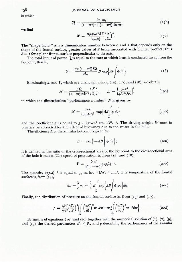
156 JOURNAL OF GLACIOLOGY
in which In w" S4 - --------' ----
o - (I -Wi)2+(1 -wf) In 'UT;' we find
w _ 7TPifLoa4AV(~)4 - 8Pwh~ So'
(17c)
The "shape factor" S is a dimensionless number between 0 and 1 that depends only on the shape of the frontal surface, greater values of S being associated with blunter profiles; thus S = 1 for a plane frontal surface perpendicular to the axis.
The total input of power Qis equal to the rate at which heat is conducted away from the hotpoint, that is,
7Ta2
( I -wi)KA. {J } Q = - cho B exp AB 4> dy . o
Eliminating ho and V, which are unknown, among (12), ( '7), and (18), we obtain
N _ AQ. ( ~ ) - (I -wi)aWt So '
( Iga)
in which the dimensionless "performance number" N is given by
1
N = ( 8;~!)t exp{AB J 4> dy} ( 19b)
o
and the coefficient A is equal to 3'4 kg wt.t cm, kW. -' . The driving weight W must in practice be corrected for the effect of buoyancy due to the water in the hole.
The efficiency E of the annular hotpoint is given by
1
E = exp{ -AB J 4> dY}; (20a) o
it is defined as the ratio of the cross-sectional area of the hotpoint to the cross-sectional area of the hole it makes. The speed of penetration is, from (12) and (18),
V =-QE - (7Tp;A )-'. (20b) a'( I -'UT~)
The quantity (7Tp;A) - I is equal to 37 m. hr. - I kW. - I cm.' . The temperature of the frontal surface is, from (13),
1 1
Bo = ~ To = ~ B J exp{AB J 4> dy}d!l . (20C)
o r>
Finally, the distribution of pressure on the frontal surface is, from (15) and (17),
(20d)
By means of equations (Ig) and (20) together with the numerical solution of (I), (7), (g), and (13) the desired parameters E, V, Bo , and p describing the performance of the annular

ISOTHERMAL SO LID-N OSE HOTPOINTS BORING IN TEMPERATE I CE 157
(coring) hotpoint can be calculated from the given quantities Q., W, and a, the given shape of the frontal surface, and the pertinent physical properties of water and ice.
Peiformance of cirwlar (non-coring) hotpoint. In the case of the circular hotpoint Rm = 0 ,
and the resulting equations are greatly simplified. The shape factor is given by
o
as in the case of the coring hotpoint, S is a number between 0 and I , greater values of S being associated with blunter profiles. Some representative profiles and their sha pe factors are shown in Figure 3. The performance number for the circular hotpoint is given by
N = AQ.S aWl'
'V:: '\ ... :'
\\,/i V ,.
5 - 0 .669 5-0.566
5-0.739
.. 1
5-1.000
~ 5 - 0 .443 S - 0 .669 5 - 0 .669 S·0.37Z
Fig. 3. Shape factors for some representative profiles of the frontal surface
in which the coefficient A as before is equal to 3 ' 4 kg wt.' cm. kW. - '. As in the case of the coring hotpoint, the driving weight W must in practice be corrected for the effect of buoya ncy due to the water in the hole. The efficiency is
I
E = exp{ -AB J 4> dy}. o
The speed of penetration is
in which the quantity (7TPi>,,) - I is equal to 37 m. hr. - I kW. - I cm! . The temperature of the frontal surface is
I I
80 = ~ T o = ~ B J exp{AB J 4> dy}dP. o ~
Finally, the distribution of pressure on the frontal surface is
'lIT
In complete analogy with the case of the annular hotpoint the performance of the circular

JOUR NAL OF GLACIOLOGY
hotpoint can be calculated from equations (21) , (22) , and (23) together with the numerical solution Of(I ) , (7), (9), and (13) ·
Numerical solution. Equations ( I ) , (7) , (9), and (13) are numerically solved for given B by a method of successive approximations. First, a trial temperature profile, T as a function of (x, is selected; next, the corresponding viscosity profile is determined (from, for example, Figure 2); then , 4> is computed from (9) by numerical integration; and, finally, a new temperature profile is found in like manner from (13). This new temperature profile is then used as the starting point for the second cycle of the process, which converges rapidly, only a few cycles being needed to attain practical accuracy.
1.0
0 .9
0 .8
0.7
1<1 0 .6 ~ ~I~ .. .;05 :---.... ~
~I I<I .... ~04
0 .3
O.l
0 .1
....
" ... 1.5 ~
... .. '" e: ~
" " 80 1.0 ~
60
... " '" '" '" ~ c:
. ~ 40 0 .5:;;
<> . ~
20 <::>
0 .0 +-~~r-r-~~~~-,~-r-r~,-~~r-r-~~~~-,-r-r-r~,-.-~r-r-r-~~~-+ O.O
1.0 2 . 0 3 .0 4 .0
Pe,formanc~ number N
Fig. 4. EJJiciency, surface temj;erature and d: /~ as Junctions oJ performance number
The approximation process is carried out for a number of values of B, and the corresponding values of E and To are obtained, from which the remaining parameters JV and 60 are easily computed by means of (19) , and (20) or (23) . These quantities are tabu lated in Table I
for 12 values of B covering the range of practical interest. The quantity d is the maximum depth in water at sea-level a t which boiling will occur a t the corresponding temperature 60 •
Figure 4 shows the efficiency and the dimension less surface temperature To plotted against the dimensionless performance number N; it summarizes in convenient form the main results of this paper.
DISCUSSION
Drilling speed. The information presented in Table I and Figure 4 shows that the efficiency E of isothermal solid-nose hotpoints decreases with increasing performance number N . This raises the interesting possibility that the drilling speed V might actually decrease with increasing power input Q, inasmuch as the effect of the increased power input m ight be more than offset by the decreased effi ciency . To show that this possibility does not arise in the range of N of practical interest, we differentiate (23b) with respect to Q, using (22 ) and the chain rule, then divide both sides by Vand simplify, obtaining
dV/~C!:- = 1 + dEjdN (24a) V Q E N ·

ISOTHERMAL SOLID-NOSE HOTPOINTS BORING IN TEMPERATE ICE 159
TABLE 1. SUMMARY OF NUMERICAL RESULTS
B N E 'To (Jo d °C , m ,
0 ' 00 0'000 1 '000 0 ' 000 0'0 0'0 0 ' 10 0 ' 294 0'950 0 ' 104 8'3 0' 0 0 ' 20 0 ' 538 0'901 0' 21 5 17 '2 0 '0 0 ' 30 0 ' 793 0 ,853 0 ' 335 26 ,8 0 '0 0 ' 40 1'070 0 ' 807 0'464 37 ' 1 0 ' 0 0'50 1 ' 376 0 ' 762 0 ' 604 48 ' 3 0 ' 0 0,60 l' 717 0'7 18 0 ' 755 60 ' 4 0 ' 0 0 ' 70 2 '097 0 , 677 0 ' 918 73 ' 4 0' 0 0 ,80 2'522 0 ' 637 1 '095 87 ' 6 0'0 0'90 2' 999 0' 599 1 '286 102 ' 9 " 2 1'00 3 ' 536 0 ' 563 "493 119 ' 5 9'4 1" IQ 4 ' 148 0'528 l' 7'9 '37'5 23'6
An identical result will be obtained for the coring hotpoint by differentiating (20b) and using (19), The function -(dE/E) /(dN/N) is plotted against the performance number N in Figure 4. Because this function never exceeds unity in the range of N of practical interest, we conclude that the dri.lJing speed always increases with increasing power input. The actual per cent increase in V per per cent increase in Q. varies from I ' 00 for N = o' 0 to o' 59 for N = 4' o.
Similar calculations show that for both circular and annular hotpoints
~/~~ = - (2 +~/~ )' (24b)
~ /dl1' = _~ ~E jdN (24C) V WE N ' , 4
t!! /~ = dE /dN V S E N'
(24d )
and
d~jdN = t!!./dN V }If E N ·
(24e)
The per cent increase in V per per cent decrease in a varies from 2'00 for JV = 0 '0 to l' 59 for .N = 4 ' o. Over the same range the per cent increase in V varies from o· 00 to o· '0 per per cent increase in 11 ', and from o ' 00 to 0 ' 4 ' per per cent decrease in S or 11 '. Thus, over the whole range in N for which the theory is valid, the drilling speed of isothermal hotpoints varies in a simple manner with respect to variations in design or operation.
Effect of turbulence , Though the theory presented in this paper is quantitatively valid only for non-turbulent flow in the layer of melt water between the hotpoint and the ice, it can give a semi quantitative indication of the effect of turbulence in the layer of melt water on the performance of an isothermal hotpoint. For fully developed turbulence K, ""'" 2CI1-" where K, is the eddy conductivity and I1-t is the eddy viscosity, which will be of order, 0 2 times the molecular viscosity 11-0' Substituting these values into the expression for A in ( '9a), we find that .1, """ A /30, hence J\'~ = N /30, and therefore that, other things being equal , turbulence in the layer of melt water should remarkably improve efficiency. Partially developed turbulence should have a similar but smaller effect.
Isothermal restriction . The assumption that the frontal surface is isothermal corresponds to
the assumption that it is composed of material with infinite thermal conductivity, or has a special shape. For real materials and nearly all shapes the boundary condition at the frontal surface will in general be a functional relationship between the temperature 'T and its normal derivative a'T /a~ on the surface ~ = 0 ; this relationship can in principle be found by solving

160 JOURNAL OF GLACIOLOGY
the heat-flow equation for the interior ofthe hotpoint (assuming that the magnitude and distribution of all heat sources and sinks except the frontal surface are known) . Only in special cases will the relationship required by the theory presented in this paper be satisfied, namely,
(IT ' dR and K in! ~ = 0 = qo dt '
where To is a constant temperature and qo is a constant heat flux independent of position. Note that implicit in the condition that the frontal surface be isothermal is the further condition that the flow of heat through any element of area of the frontal surface be proportional to the area of the projection of the element on a plane perpendicular to the axis ofthe hotpoint.
One way to test the assumption for a given design is to calculate, by numerical methods, if necessary, the heat flow at the frontal surface that would occur if the surface were actually isothermal. The degree to which this calculated heat flow agrees with the required heat flow is a measure of the applicability of the theory. A misfit ofa few per cent probably is not crucia l. In any case, if the calculated value of qo increases with increasing t, then the hotpoint wi ll be less efficient than predicted by the theory, and conversely. This follows because, if qo .is less at the center, the "cool" center will be "slower" than the hotter outer zone of the frontal surface, hence the effluent melt water at the outer edge of the hotpoint, being hotter, will carry away a larger fraction of the total heat available.
E;ffect of corrosion. If the frontal surface of an isothermal hotpoint becomes coated with a thin layer of poorly conducting material, for example by becoming corroded, the drop in temperature across the insulating layer will be greatest where the heat flow is greatest. Thus, by the same reasoning as for the non-isothermal hotpoint, if dR jdt decreases with increasing t (the usual case), then corrosion will cause a decrease in efficiency, and conversely.
Design of hotpoints. Although the theory presented in this paper applies specifically to isothermal hotpoints, it can also be used to estimate the approximate drilling speed and efficiency of non-isothermal designs in terms of power input, driving weight, inside and outside diameter of hot point, and shape of frontal surface, thus facilitating selection of the optimum design for a given application without the time and expense of building and testing a long series of prototypes. Even more important, it enables the designer to estimate at least approximately two other highly important parameters in the design, the temperature of the frontal surface , and the magnitude and distribution of pressure on it, thus permitting much smaller factors of safety than would otherwise be possible.
ACKNOWLEDGEMENTS
This problem was formulated and partially solved while I was a National Science Foundation postdoctoral research fellow at the Swiss Federal Institute of Technology. Professor Dr. G. Schnitter, Director of the Laboratory for Hydraulic Research and Soil Mechanics at the Institute, and Ing. P. Kasser, Chief of the Section for H ydrology and Glaciology of the Laboratory, generously gave me free use of space and facilities, and otherwise indirectly contributed to the work reported in this paper.* I am pleased to express here my appreciation to Dr. W. H. Ward and Professor W . B. Kamb for reading and commenting on the original manuscript ; their suggestions have resulted in a number of significant improvements in this paper, though, of course, they do not thereby undertake responsibility for any of its contents. I also wish to thank Professor Gerhard Oertel for helping me with the German abstract. The numerical computations were performed on the Bendix G- I 5 computer in the Institute of Geophysics of the University of California.
MS. received 22 November 196r
• A review by Dr. Shreve of Ing. P. Kasser's recent paper on a light thermal ice-drill appears all p. 234 of this issue.- Ed.